

Page 1
EARTH GROUND ROD INSTALLATION
Proper grounding gives an electrical charge, such as from an electrical static
discharge or a near lightning strike, a path from which to dissipate its energy safely
into the earth.
Without this path, the intense energy generated by lightning could be directed
towards the Phone system. Although nothing can absorb the tremendous power of a
direct lightning strike, proper grounding can protect the Phone system in most
cases.
The type and length of earth ground rods vary by region. Contact the building
inspector’s office in the municipality where you plan to install the unit for correct
grounding materials and installation procedures.
Before digging, contact local underground utility locating companies.
Avoid damaging gas, power, or other underground utility lines.
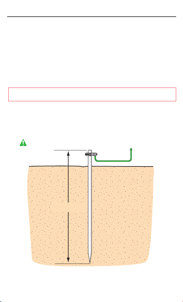
The earth ground rod must be located within 3 feet from the Phone system.
The ground wire must be a single, whole piece of wire. Never splice two wires for the
ground wire. If you should cut the ground wire too short, break it, or destroy its
integrity, replace it with a single wire length.
The earth ground rod must be located within
3 feet from the equipment being grounded.
to equipment to be grounded
12 Gauge Wire
For the correct depth,
consult the local code
Warning:
Not responsible for improper installation or failure to comply with all necessary
local building codes.
Page 2
C
V
B
N
M
’
X
Z
A
Q W
E
R
T Y U I
0
7
4
1
2
3
5 6
8
9
O
P
S
D F
G H J
K L
SPACE BAR
EXIT
HELP
PROGRAM
ERASE
ENTER
BACK
SPACE
SHIFT
Unprotected
Side
Transformer
WhiteBlack
Protected
Side
Chamberlain Elite Phone System
(
NOT
equipped with a built-in surge suppressor board)
15 Pin Input/Output
Connector
Chassis Ground
12 Gauge Wire
Refer to Earth Ground
Rod Installation
12 VAC
POWER
WHITE:
BLACK:
GREEN:
OUT IN
CHASSIS
GROUND
12 VAC
Page 3

Transformer
POWER INPUT RS 485 WIRING
Typical RS 485 Device
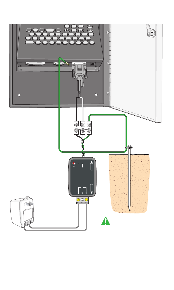
Install surge suppressor module within 5 ft of Phone equipment to be protected.
Connect the
side black and white wire terminals of the surge suppressor
module to the power input of the Phone equipment to be protected.
(Polarity does not matter)
Connect the side of the surge suppressor module to the transformer screw
terminals. (Polarity does not matter)
Note: Center terminal is not used.
Connect the green “Chassis Ground” of the surge suppressor module to the earth
ground rod.
Connect the chassis ground of the equipment to the earth ground rod.
(Refer to earth ground rod installation for details)
IN
1
2
3
4
5
NO
GREEN
RED
YELLOW
COM
NC
NO
COM
COMM
RS-485
NC
GND (+) (–)
EXIT
SWITCH
RF INPUT
ON
D3
D7
D4
OFF
TERMINATE
DEVICE ID NUMBER
100'S 10'S 1'S
POWER
INPUT
STRIKE
RELAY
DISARM
RELAY
It is important that the chassis grounds on the suppressor, RS 485 device and Entry
Phone system are properly grounded. (Refer to Earth Ground Rod Installation.)
Unprotected
Side
Protected
Side
12 Gauge Wire
Chassis
Ground
Refer to Earth Ground
Rod Installation
OUT
12 VAC
POWER
WHITE:
BLACK:
GREEN:
OUT IN
CHASSIS
GROUND
12 VAC
Page 4

POWER INPUT SURGE SUPPRESSOR MODULE
(Low Voltage 12 VAC)
This power input surge suppressor module is specifically designed to prevent
damage caused by near-lightning strike or electrostatic discharge on a power
input port.
This module will work on Chamberlain Elite systems (
built-in surge suppressor board) and all Chamberlain Elite RS 485 devices. For
installation instructions refer to the next pages.
Install in water resistant enclosure
Power On
LED indicator
12 VAC
CHASSIS
NOT
equipped with a
Protected
Side
For “indoor” use only.
GROUND
For Technical Support: 1-800-528-2806
Warning: The Chamberlain Group, Inc. does not warrant nor assumes liability for
TAPISS installed in non Chamberlain Group, Inc. enabled controllers.
© 2005 The Chamberlain Group, Inc.
All Rights Reserved
114A2918
845 Larch Avenue Elmhurst, Illinois 60126 www.chamberlain.com
POWER
BLACK:
WHITE:
12 VAC
GREEN:
OUT IN
Unprotected
Side
®
™
 Loading...