

Page 1
To comply with FCC/IC rules, adjustment or modification of receiver
and/or transmitter is prohibited, except for changing the code setting
and replacing the transmitter battery. THERE ARE NO USER
SERVICEABLE PARTS.
WARNINGWARNING
Disconnect power to the garage door or gate
opener before installing the receiver.
Children operating or playing with a garage door or
gate opener can injure themselves and others.
garage door or gate could close and cause serious
injury or death.
push buttons or the remote control transmitters.
Install the receiver (and any additional push
buttons) out of the reach of children and away from
all moving parts of the door or gate and its
hardware, but
Do not allow children to operate the
where the garage door or gate is
visible.
A moving garage door or gate could injure
someone under it.
the door or gate is properly adjusted, you can see it
clearly, and there are no obstructions to door or
gate travel.
Activate the opener only when
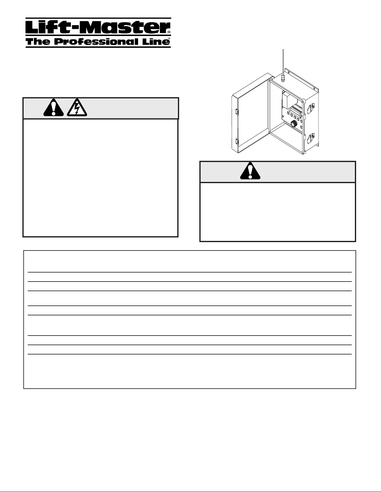
The
Access Control Receiver
ACRx2000
OWNERS MANUAL
WARNING
Install the control station and receiver where the
door or gate is visible, but away from the door or
gate and its hardware. When a receiver is used to
activate a commercial door opener, a reversing
edge MUST be installed on the bottom of the door.
Failure to install a reversing edge under these
circumstances may result in serious injury or death
to persons trapped beneath the door.
FEATURES
Code Memory
Input/Output Connections
Power Supply
Output Control Circuit
Output Control Rating
Case
Display
Time Clock
RS-232 Interface
INTRODUCTION
The ACRx2000 is a radio receiver which controls a gate or door
opener. It can recognize as many as 1,000 different transmitters.
It assigns a unique identification code to the user of each
transmitter, and can produce a record of when each one is used to
gain access. The ACRx2000 can be easily programmed by any
authorized person to add new users, remove users, suspend users
temporarily, or open the gate or door by pushing one button. It
can be connected to a computer for additional control and
recordkeeping functions.
1000 users with unique radio codes . Any combination of 60, 80, 90, 400, 900 series transmitters and
keypads. Supports Dip, Billion, “Security +, and “Homelink” code formats. Each radio code can have a 5
digit alpha-numeric user name assigned to it.
Terminal block inside case. Two screws each for power, relay output, and command.
24 V AC/DC or 12 V DC.
Relay switching controlled by radio transmitters, or GRANT ACCESS button on control panel, or external
push-button.
Relay Switches Up to 3 Amps at 37 VAC max.
The ACRx2000 is mounted in an 11" x 13" x 6" fiberglass enclosure, with an integrated hinged lid. All
electrical connections can be made through a conduit hole; a type-F connector is available externally for
antenna mounting.
16 Character non-backlit, LCD display
Time and date are maintained by a real time clock with battery backup. Expected battery life is 10 years.
An RS-232 interface is provided. This interface is 1200-9600 Baud, 8 bits, no parity, 1 stop bit. This
allows use of a computer or printer to record access transactions. This interface can also be used to
back up code memory to a computer with the use of Microsoft Windows-compatible software available
from Lift-Master.
Once the ACRx2000 is installed, it may be programmed by
installer or by the custodian of the gate. The same procedures
the
are used to make changes at a later time.
INSTALLATION
Mechanical and electrical installation must be performed by
qualified, professional service personnel. Knowledge of electrical
codes may be necessary when wiring AC power and certain door
actuators. If in doubt, consult with Lift-Master commercial
product service at 1-800-588-2806.
Page 2
RELAY OUTPUT
N.O. contacts
SERIAL PORT
12
SELECT
24
VAC
12/24
VOLTS
AC/DC
EXT.
GRANT
SWITCH
N.E.C. CLASS 2
WIRING ONLY
Radio Power
Common
Push Button
Doorbell
Button
Voltage select jumpers:
Place jumpers on bottom 2 pins for 24V operation
Place both jumpers on top 2 pins 12v operation
ACRx2000 & ANTENNA MOUNTING INSTRUCTIONS
Mounting the Box
Choose a location for the ACRx2000 control box which is:
• Protected from tampering
• As close to the approaching vehicles as possible for best
reception.
• Suitable for permanent attachment by mounting screws.
• Accessible to necessary wiring.
Hold the ACRx2000 control box in its intended mounting
location. Make sure the cover opens freely, with the display and
controls at a comfortable height and angle for viewing and use.
Use the holes in the ACRx2000 box for marking and drilling
attachment holes.
Antenna Placement
For best range, placement of the antenna is crucial. Follow
these guidelines for best results.
•Make sure there is no interfering signal an the same channel as
the ACRx2000. You can monitor channel activity with the
Liftmaster M-18 Test Set. On-channel interference is not only
due to transmitters, but can also be caused by computing
devices, security systems, and other nearby electronic devices.
Power invertors and battery chargers are known sources of
interference.
• The ACRx2000 antenna system can be configured in several
ways. Each installation is different, so there is no best antenna
system. Try the different configurations of antenna placement
until the best range is encountered. Do this BEFORE hard mounting the antenna and permanently routing the cable.
The typical antenna configurations are as follows on page 3:
• The antenna must not be next to, or enclosed in, metal.
• Place the antenna outside of any housing, box, or building,
even if the housing is not made of metal. Non-metallic
structures can contain conduit, metallic-foil insulation, or be
painted with metallic paint.
• Place the antenna as high as possible, in sight of the expected
location of the transmitters. This is very important.
• Consider the direction from which the transmitters will be
used. Place the antenna so that there are no structures or metal
obstructions between the transmitters and receiving antenna.
• If longer coaxial cable is needed, do not splice cables together.
Instead, purchase a ready-made cable of the desired length from
a radio/tv store. Use 75-ohm cable with CATV connectors
(also called type “F” connectors).
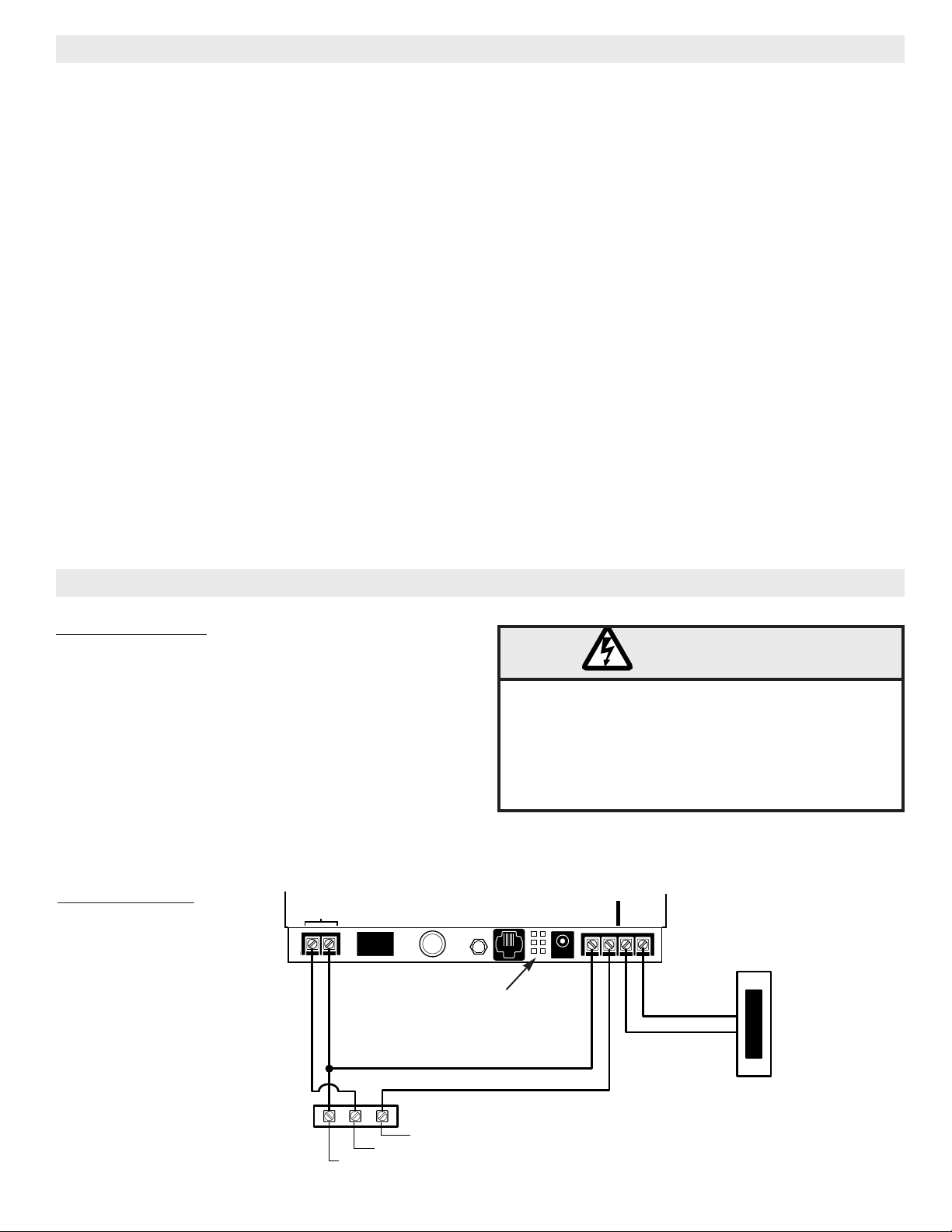
WIRING INSTRUCTIONS
Wiring requirements
Power can be provided with an 85LM wall mount transformer or
Radio Power from a gate operator (17 to 37 V AC/DC at 150
mA or 12 VDC at 200 mA minimum.)
Using an 85LM wall mount transformer: Install the voltage
select jumpers (J4 & J6) in the 24v position and plug the
transformer jack into the receptacle to the right of the voltage
jumper. Wire the relay contacts to Push Button and Common as
shown in the wiring diagram
Using gate/door operator power: Install the voltage select
jumpers (J4 & J6) in the position that matches the power
supplied by the operator. Wire ACRx2000 to the operator as
shown in the wiring diagram.
WIRING DIAGRAM
WARNING
The ACRx2000 uses low voltage wiring only. Attach
the ACRx2000 only to circuits or devices that are NEC
Class 2 (less than 37VAC). Do not run wires to or from
the ACRx2000 in any conduit or box where there are
AC supply (120VAC) circuits. Failure to follow this
warning could result in electrical shock or fire and
damage to the ACRx2000.
2
Page 3
GRANT ACCESS
0-9, A-Z
SCROLL
BLOCK USERDELETE USER
ENTERADD USERSETUP/EXIT
RELAY OUTPUT
N.O. contacts
SERIAL PORT
VOLT
SELECT
24
VAC
12/24
VOLTS
AC/DC
EXT.
GRANT
SWITCH
N.E.C. CLASS 2
WIRING ONLY
TM
2000
l
l
GRANT ACCESS
0-9, A-Z
SCROLL
BLOCK USERDELETE USER
ENTERADD USERSETUP/EXIT
RELAY OUTPUT
N.O. contacts
SERIAL PORT
VOLT
SELECT
24
VAC
12/24
VOLTS
AC/DC
EXT.
GRANT
SWITCH
N.E.C. CLASS 2
WIRING ONLY
l
TM
2000
l
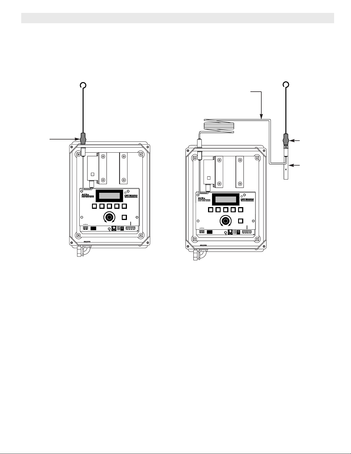
ANTENNA CONFIGURATIONS
A. Direct Mount (Intermediate Radio Range)
Antenna is mounted direct to outside of ACRx2000
enclosure.
ANTENNA
B. Remote Mount (Maximum Radio Range)
Antenna is mounted away from the ACRx2000 at the end of
the 15ft coax cable.
COAXABLE CABLE
ANTENNA
MOUNTING
BRACKET
3
Page 4

OPERATION
The controls and display on the ACRx2000 panel are very
simple for ease of operation. Most programming tasks require
pushing one button for the desired operation, then completing
the displayed instructions. A summary of these procedures is
printed inside the ACRx2000 panel door.
Before use, each transmitter must be programmed into the
system by the Add Users function. This “learns” the unique
radio code of that transmitter, and assigns it a User ID code
chosen by the programmer; this User ID may be the user’s
name, unit number, or any combination up to five letters and
numbers. Once programmed, the transmitter can be used to
control access. The ACRx2000 can output the date, time, and
User ID for each access. User IDs can be Deleted when no
longer allowed, or Blocked from access temporarily. A Setup
function is used to set the time, date, and other details of
ACRx2000 operation.
Setup
Basic settings on the ACRx2000 are changed through the Setup
routine. These include the time, date, and other optional settings.
To change any of the following items, press the SETUP/EXIT
button. The message “scroll for MENU” will appear; turn the
dial to choose the item that you want to change, then press the
ENTER button.
If you wish to leave the Setup mode without doing anything,
press SETUP/EXIT again to return to the regular display, which
shows the date and time alternately.
Change PASSWORD: A password may be used to protect the ACRx2000 against unauthorized access. The unit is shipped with the Password function disabled. To enable this feature, select a four digit password composed of letters and/or numbers. Once a password has been entered no changes can be made to the ACRx2000 memory without supplying the password. If you
forget your password, it cannot be retrieved.
To disable the Password function, change the password to all
spaces.
Set the TIME: When “Set the TIME” is displayed and you press ENTER, the current time will be displayed in hour/minute/second/AM-PM format. The first digit will be underlined. Turn the dial until that digit is set, then press ENTER. Repeat until all digits are correct. Press ENTER one more time and the time is set. “Set the TIME” will be displayed again. Press SETUP/EXIT to return to the regular display.
Set the DATE: When “Set the DATE” is displayed and you press ENTER, the current date will be displayed in month/day/year format. The first digit will be underlined. Turn the dial until that digit is set, then press ENTER. Repeat until all digits are correct. Press ENTER one more time and the date is set. “Set the DATE” will be displayed again. Press SETUP/EXIT to return to the regular display.
Set RELAY Mode: The method of relay operation depends on
the type of gate or door opener the ACRx2000 is controlling.
The three types of operating modes are described as follows:
• Momentary Close: The relay contacts will close for 1/3
seconds each time a valid user’s transmitter code is received.
This is the factory default state of the ACRx2000, and the
most commonly used.
• On When Receiving: The relay contacts will close when a
valid transmitter code is received, and remain closed until the
user releases his transmitter button.
• Toggle ON/OFF: The relay contacts will close when a valid
transmitter code is received, and remain closed until the next
one is received. The relay will continue to toggle ON/OFF in
this manner for each valid code received. This mode is useful
when the relay must stay on after the user releases his
transmitter button.
Set BAUD RATE: When “set BAUD RATE” is displayed and
you press enter, a message appears which instructs you to scroll
for the baud rate selections. Turn the scroll knob until the
desired rate appears, and the press ENTER. Selectable baud
rates are 1200, 2400, 4800, and 9600 baud. This is only
applicable to the RS232 port of the ACRx2000. If you are not
using the ACRx2000 with an external printer or a computer,
then you do not have to be concerned with this setting.
NOTE: once a new baud rate is selected, it does not take
affect until the ACRx2000 is turned off and re-powered.
Add User
Each 80 series “Billion Code” or 90 series “SECURITY PLUS”
transmitter is uniquely coded at the factory; no two transmitters
have the same code. When adding a user there is no need to
program the transmitter or set code switches. If using 60 series
(or older) transmitters, each transmitter should have a different
code setting.
Press the ADD USER button to choose the Add User mode. The
display will show “USER ID = _____”. Turn the dial until the
first letter of the desired User ID is shown, then press ENTER.
Repeat until all the letters or numbers (up to five) are displayed.
Press ENTER twice to confirm that User ID.
Instead of selecting a custom User ID yourself, the ACRx2000
can choose a number for you. Simply press ENTER 5 times when
“USER ID _” is displayed (enter a User ID of all blanks), and
the next ID number in sequence will be automatically assigned.
This will be a numerical only ID.
The display will now show “TRANSMIT NOW!” and the green
light next to the display will stay on. Press the button on the
transmitter for that User ID. The display will show “Add User
COMPLETE”. That transmitter is now an authorized user; when
pressed, it will grant access for that User ID.
If there is a mistake or a problem at any time, press
SETUP/EXIT to start over. These steps can be repeated to add
more users.
Delete User
Press the DELETE USER button. The display will show “USER
ID = _____”. Turn the knob until the first letter of the User ID is
shown, then press ENTER. Repeat until the entire User ID is
displayed.
The display will show “DELETE <USER ID>?” Press ENTER
to delete that User ID, or EXIT to cancel and start over.
After ENTER is pressed, the display will flash “Del Usr
COMPLETE”. When a User ID is deleted, the ACRx2000 will
no longer respond to that transmitter and all record of that user
is deleted from the ACRx2000.
4
Page 5

Block and Unblock Users
Press the BLOCK USER button. The display will show “USER
ID = _____”. Turn the knob until the first letter of the User ID is
shown, then press ENTER. Repeat until the entire User ID is
displayed.
The display will show “BLOCK <USER ID>?” Press ENTER to
temporarily block that User ID, or EXIT to cancel and start over.
When a User ID is blocked, the ACRx2000 will display the
attempted entry as “BLOCKED:_____”, and will not open the
gate. Time and date of the attempted entry is available at the
computer serial port.
To unblock a user, press the BLOCK USER button and repeat
the steps used to choose the User ID. The display will show
“UNBLOCK <USER ID>?” Press ENTER to unblock that user,
or EXIT to cancel and leave the user blocked.
TRANSMITTER/WIRELESS OPERATION
Whenever the ACRx2000 is displaying the date and time, it is
ready to respond to a transmitter. If a transmitter button is
pushed, the green light next to the display will flash. If the code
matches a valid User ID which is not blocked, access will be
granted and the display will show “Access OK: <User ID>”. If
the code matches a blocked User ID, access will not be granted
and the display will show “Blocked: <User ID>”.
MANUAL OPERATION
The gate or door can be manually operated by pressing the
GRANT ACCESS button on the panel, or by closing any
contacts connected to the External Grant Switch terminals. If
Operator Password is enabled, the ACRx2000 will ask for the
correct 4-digit password before closing the contacts.
“Blocked: <User ID> at <time/date>”. This prints each time a
transmitter code is received which is blocked. Access is not
granted. The User ID of the transmitter and the date and time of
the attempt are recorded.
(In all these cases the date and time recorded depend upon the
date and time being correctly set in the ACRx2000. To change
the date or time, refer to the Setup section of these instructions.)
When attached to a serial interface port of an MS-DOS
computer equipped with Microsoft Windows®and LiftMaster’s
own Total Control software, the ACRx2000 can be remotely
programmed and activity recorded. For more information about
this feature, call your local Lift-Master dealer.
COMPATIBLE PRINTERS
The ACRx2000 1000 is compatible only with standard RS-232
line printers. If a printer is needed we highly recommend LM
Part No. 55-SP312FD40 for capatibility reasons (refer to
drawing below).
PRINTER 55-SP312FD40
FRONT COVER
SERIAL PORT
The ACRx2000 includes a computer connection which can be
used to attach a computer or printer. This is a standard
RS-232 serial port, although a special adapter cable is required
to connect to the ACRx2000.
When attached to a serial interface computer printer, the
ACRx2000 will print a log of all activities as they occur. Line
messages include:
“self-test PASSED at <time/date>”. This is printed when the
ACRx2000 is turned on or reset.
“Access OK: <User ID> at <time/date>”. This prints each time
a valid transmitter code is received and access is granted. The
User ID of the transmitter and the date and time of access are
recorded. (Transmitter digital code is not printed.)
POWER OFF
5
Page 6

GRANT ACCESS
0-9, A-Z
SCROLL
BLOCK USERDELETE USER
ENTERADD USERSETUP/EXIT
RELAY OUTPUT
N.O. contacts
SERIAL PORT
VOLT
SELECT
24
VAC
12/24
VOLTS
AC/DC
EXT.
GRANT
SWITCH
N.E.C. CLASS 2
WIRING ONLY
TM
2000
l
l
COMPONENT LAYOUT
Antenna
Mounting
Holes
Display
Output
Terminals
Serial Port
for Computer
or Printer
Voltage Select
Jumpers
Display Contrast
Adjustment
Grant
Access
Button
Power Supply
Inputs
6
Page 7

TROUBLESHOOTING
Problem Remedy
LCD display is blank. •
LCD display is on but ACRx2000 does not function properly.
Turn power off, then on again.
•
All users have short radio range, green light is flashing.
•
A transmitter is stuck on. Use M-18 test set to locate and disable transmitter.
All users have short radio range, green light is off. •
A single user has short radio range. •
A single user cannot obtain access. Green light
on ACRx2000 flashes, LCD message does not change. •
A single user cannot obtain access. Green light •
reprogram
on ACRx2000 does not flash.
When Grant Access button is pushed, ACRx2000 relay
clicks but door/gate does not open. •
ACRx2000 prints incorrect time/date. •
routine.
Power not connected; check plug and wires.
•
ACRx2000 is broken; repair or replace.
•
Check 24V/12V jumper.
Radio interference; try moving antenna location.
Replace transmitter battery, or move transmitter to
a different place in car.
Repeat the
Replace transmitter battery, or replace and
transmitter.
Check door operator and wiring.
Time or date is wrong. Do
•
Clock backup battery needs replacement.
Add User
routine.
Set Time
or
Set Date
No users can access ACRx2000, LCD display is on. •
REPLACEMENT KITS
Part Number Description
K79-15418 Main Printed Circuit Board Assembly
K75-15665 Radio Enclosure & PCB Assembly
K74-16018 Antenna and Mt’g Bracket Kit
ACRx2000 must be in the idle state, with time and
date displayed. Press SETUP/EXIT, or cycle power
to ACRx2000.
SERVICE INFORMATION TOLL FREE NUMBER (U.S.A.): 1-800-588-2806
IN CANADA: 1-800-654-4736
7
Page 8

01-15562B All Rights Reserved Printed in Mexico
©1999, The Chamberlain Group, Inc.
 Loading...