

Page 1
Children operating or playing with a garage door opener
can injure themselves or others. The garage door could
close and cause serious injury or death. Do not allow
children to operate the wall push button(s) or remote
control(s).
A moving garage door could injure or kill someone under
it. Activate the opener only when you can see the door
clearly, it is free of obstructions, and is properly adjusted.
WARNING
Features:
• This Remote Control Security Transmitter can be used with
most 390 MHz Lift-Master garage door openers sold since
1987. This includes “Smart” openers as well as openers with
9 switch-settable codes. (It is not compatible with 8 switchsettable codes.) This transmitter can be used as a
replacement for, or in addition to, most older style
transmitters.
• Personalized codes: Up to 3900 possible combinations.
Code can be easily changed. Different codes can be
programmed for use with more than one “Smart” opener.
• Flexible code length: Codes can be 2, 3, 4, or 5 digits.
• Power Supply: 9 volt battery.
Operation:
To activate the opener, press the numbers for your security
code and then press ENTER. The buttons will blink for 15
seconds after the code is transmitted. During that time, the door
can be stopped or reversed by pressing ENTER again.
If you accidentally press a wrong number, press ENTER and
start again. For convenient operation in the dark, the buttons will
light when any button is pressed.
Setting the code:
The opener and transmitter must be set to the same code
before they will work together. If you have a “Smart” opener
(with controls resembling Figure 3, below right), it will learn any
code you choose. Just follow the numbered instructions below.
If you have a “Smart” opener and also wish to continue using
older transmitters (the kind with a red light on the front and
switches inside for setting the code), then you must choose a
4-digit code. Follow the numbered instructions below to teach
your opener the code you choose, then use the instructions on
the other side to set the switches inside your older transmitters
to work with this new code.
If you have an older style opener which has switches for setting
the code, then skip the instructions below. Follow the
instructions on the other side to set the switches inside your
opener.
1. Decide on a 2, 3, 4 or 5 digit code using numbers from
0 to 9. Numbers may be used more than once (for example,
4, 0, 4, 1). Numbers that share the same button produce the
same code (i.e., 1 and 2, 3 and 4, etc.).
2. Press the selected digits on the transmitter buttons. (Do not
pause for more than 10 seconds, or the button light will turn
off and you will have to begin again.) Then press the ENTER
button and hold it down. (Do not hold it for more than two
minutes.)
3. While holding the ENTER button, press and release the
“Smart” button on the opener end panel (see Figure 3). The
green indicator light on the opener will flash and the door
may move. Release the ENTER button on the transmitter. To
stop or reverse the door press ENTER again.
Now the opener will operate whenever the transmitter code
followed by the ENTER button is pressed.
If you have any other transmitters, test to make sure they can
open the door. If they are the old style with a red light,
reprogram them according to the instructions on the other side.
To change codes at any time, repeat steps 1-3.
Model 99LM
Remote Control Security Transmitter
OWNER’S MANUAL
©
Figure 2
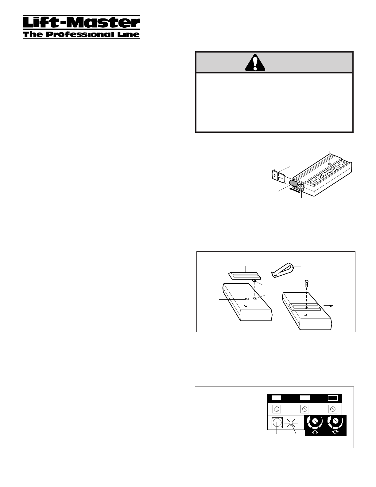
To attach the transmitter to your car visor:
• Remove the visor clip from the clip holder.
• Remove the case screw. Insert tab on clip holder through
circular label and into case (Figure 2). Slide clip holder forward.
• Replace the case screw (do not overtighten). Slide visor clip
onto clip holder.
Battery:
The 9 volt battery should
produce power for at least
one year. As long as there is
adequate power, the buttons
will illuminate and the opener
will operate when the code
followed by the ENTER key
is pressed. Replace the
battery when button
illumination becomes dim.
To change the battery, remove the battery compartment cover
and unsnap the connector (see Figure 1). Remove the battery
and replace with a fresh 9V alkaline battery only. Snap the
connector onto the new battery and replace the compartment
cover.
To comply with FCC rules, adjustment or modification of receiver and/or
transmitter is prohibited, except for changing the code setting or replacing the
battery. THERE ARE NO OTHER USER SERVICEABLE PARTS.
Figure 3
Representative
Garage Door Opener
with "Smart" Button
Figure 1
1
WARNING
Battery
Compartment
Cover
Connector
Battery
Case
Screw
Bottom of
Remote
Case
Clip Holder
Tab
Label
1
"Smart"
Button
Green
Indicator Light
2
1
Visor Clip
2
9
7
5
KG
Test Light
4
3
Case
Screw
1
3
ENTER
0
9
8
7
6
5
Slide
Clip Holder
3
9
1
7
3
5
KG
Page 2
© 1995, Chamberlain Group, Inc.
114A1824D All Rights Reserved Printed in Mexico
For service in the U.S.A., dial our toll-free number: 1-800-528-9131
in Canada, dial: 1-800-654-4736
9V battery ....................................................................................10A16
Visor clip ....................................................................................29C128
Keypad.....................................................................................180D173
Visor clip holder ......................................................................31C412-1
Remote case only.....................................................................41A4797
(circuit board not included)
Replacement parts:
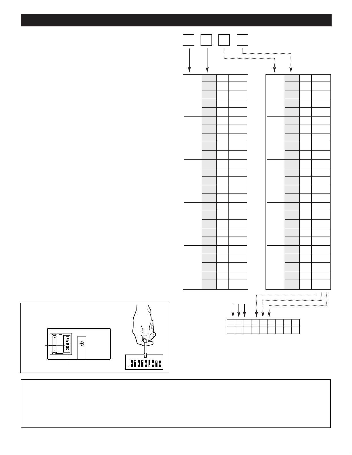
Code Switch Selection
The Remote Control Security Transmitter has no switches
inside, but some older transmitters and openers do. In order
for them to work together, you must set the switches in the
older devices to match the security code you choose.
First, decide on a 4-digit number code. Write the number in
the 4 blank boxes above the chart.
Look at the first digit you have chosen, on the left. Follow the
arrow straight down until you find that number in the chart,
directly below the box. (Remember that there are two
numbers on each transmitter button, so 1
|
2 means 1 or 2, 3|4
means 3 or 4, etc.) Put your finger on that spot.
Now look at the second digit you have chosen. Follow the
second arrow straight down the shaded column until you find
that number in the same section as the first one. Put a check
mark next to those numbers. (For example, if your first
number is 1 and your second number is 0, then you should
have marked the row that contains 1
|
2 - 9|0.)
In the row you just marked, there are three symbols on the
right side. They are some combination of
+, 0, and – . Copy
these symbols straight downward into the first three blank
boxes (labeled 1, 2, 3) below the chart.
Now repeat the procedure. Go back above the chart and find
the third digit you chose. Follow the dotted line down the right
hand chart until you find that number. Then take the fourth
digit and follow the second dotted line down the shaded
column until you find that number in the same section as the
third one. Put two check marks in that row.
Now copy this set of symbols down into boxes 4, 5, 6 below
the chart. Boxes 7, 8, 9 are already filled in because these
settings are always the same.
Code Switch Setting
The chart with nine symbols shows how to set the code
switches in any transmitter or opener. To find the switches on
a red light transmitter, see Figure 4 below. To find the
switches on an older style opener, see its instructions or call
our toll-free number for assistance.
The switches are a tiny block of nine 3-position switches
which are marked 1 through 9 and
+ 0 –. Use a pen point or
other small tool to set the switches to match the settings at the
bottom of the worksheet.
After reassembly, test all transmitters to be sure they open the
door.
1|2 – – –
3| 4 0 0 +
5| 60 0 –
7| 8 0 + 0
9| 0 0 + +
1|2 0 + –
3| 40 – 0
5| 60 – +
7| 80 – –
9| 0 + 0 0
1|2 + 0 +
3| 4 + 0 –
5| 6 + + 0
7|
8 + + +
9|
0 + + –
1|
2+ – 0
3|
4+ – +
5|
6+ – –
7|
8 – 0 0
9|
0 – 0 +
1|
2 – 0 –
3|
4 – + 0
5|
6 – + +
7|
8 – + –
9
|0 – – 0
+ ––
123456789
Figure 4
Transmitter Circuit Board
✔ ✔✔
CODE MATCHING PROCEDURE FOR USE WITH OLDER TRANSMITTERS /OPENERS (WITH RED TEST LIGHTS)
1|2
3
|
4
5
|
6
7
|
8
9
|
0
1|2 – – –
3| 4 0 0 +
5| 60 0 –
7| 8 0 + 0
9| 0 0 + +
1|2 0 + –
3| 40 – 0
5| 60 – +
7| 80 – –
9| 0 + 0 0
1|2 + 0 +
3| 4 + 0 –
5| 6 + + 0
7|
8 + + +
9|
0 + + –
1|
2+ – 0
3|
4+ – +
5|
6+ – –
7|
8 – 0 0
9|
0 – 0 +
1|
2 – 0 –
3|
4 – + 0
5|
6 – + +
7|
8 – + –
9
|0 – – 0
1|2
3
|
4
5
|
6
7
|
8
9
|
0
Match
Code
Switches
(1-9)
23456789
1
0
+
Code Switches (1-9)
2345678
1
+
0
9
Page 3

Les enfants qui font fonctionner ou qui jouent avec un
ouvre-porte de garage peuvent se blesser eux-mêmes
ou bien d’autres personnes. La porte du garage pourait
se fermer et provoquer des blessures graves ou la mort.
Ne pas laisser les enfants se servir de bouton-poussoirs
muraux ou de télécommandes.
Une porte de garage en mouvement pourait blesser ou
tuer quelqu’un se trouvant sous celle-ci. Activer l’ouvre-
porte seulement lorsque la porte est en pleine vue,
qu’elle est libre de toute obstruction, et qu’elle est
correctement réglée.
WARNING
CAUTION
WARNING
AVERTISSEMENT
WARNING
AVERTISSEMENT
Charactéristiques:
• Cet Émetteur de Sécurité à Télécommande peut être utilisé avec la
plupart des ouvre-portes de garage 390 MHz Lift-Master vendu
depuis 1987. Sont inclus les ouvre-portes “Smart” ainsi que les
ouvre-portes à combinaisons réglables par 9 interrupteurs. (Il n’est
pas compatible avec les combinaisons réglables par 8 interrupteurs.)
Cet émetteur peut être utilisé en remplacement ou en supplément de
la plupart des autres anciens types d’émetteurs.
• Combinaisons personnalisées: jusqu’à 3900 combinaisons sont
possibles. La combinaison peut être facilement changée. Des codes
différents peuvent être programmés pour l’utilisation avec de
multiples ouvre-portes “Smart”.
• Longueur des combinaisons flexible: les combinaisons peuvent avoir
2,3,4 ou 5 chiffres.
• Alimentation: pile de 9 volts.
Fonctionnement:
Pour activer l’ouvre-porte, appuyer sur les numéros de votre
combinaison de sécurité puis appuyer sur ENTER. Les touches
clignoterons pendant 15 secondes après que le code sera transmis.
Durant cette période, la porte peut être arrêtée ou inversée en appuyant
encore sur ENTER.
Si vous appuyer accidentellement sur une mauvaise touche, appuyer sur
ENTER et rcommencer. Pour utilisation pratique dans le noir, les
touches s’allument lorsque n’importe quelle touche est appuyée.
Réglage de la combinaison:
L’ouvre-porte et l’émetteur doivent être réglés à la même combinaison
pour qu’ils puissent fonctionner ensemble. Si vous possédez un ouvreporte “Smart” (dont les contrôles ressemblent ceux de la Figure 3, en
bas à droite), il apprendra n’importe quelle combinaison que vous
choisirez. Simplement suivre les instructions numérotées qui suivent.
Si vous possédez un ouvre-porte “Smart” et souhaitez utiliser aussi des
émetteurs plus anciens (ceux qui ont une lampe rouge sur la face et des
interrupteurs à l’intérieur pour réglage de la combinaison), alors vous
devez choisir un code à quatre chiffres. Suivre les instructions
numérotées qui suivent pour apprendre à votre ouvre-porte la
combinaison de votre choix, ensuite suivre les instructions qui se
trouvent de l’autre côté pour ajuster les interrupteurs à l’intérieur de
votre ancien émetteur de façon qu’il fonctionne avec ce nouveau code.
Si vous possédez un type d’ouvre-porte plus ancien qui a des
interrupteurs pour le réglage de la combinaison, ignorer les instructions
qui suivent. Suivre les instructions qui se trouvent de l’autre côté pour
ajuster les interrupteurs à l’intérieur de votre ouvre-porte.
1. Choisir une combinaison à 2, 3, 4 ou 5 chiffres en utilisant des
numéros de 0 à 9. Les numéros peuvent être utilisés plusieurs fois
(par exemple, 4, 0, 4, 1). Les numéros qui se partagent la même
touche produisent le même code (c’est-à-dire, 1 et 2, 3 et 4, etc.).
2. Appuyer sur les touches sélectionnées de l’émetteur. (Ne pas attendre
plus de 10 secondes, sinon la lumière de la touche s’éteindra et il
vous faudra recommencer.) Ensuite appuyer sur la touche ENTER et
la maintenir appuyée. (Ne pas la maintenir plus de deux minutes.)
3. Alors que la touche ENTER est maintenue, appuyer et relâcher le
bouton “Smart” sur le panneau de l’ouvre-porte (voir Figure 3). La
lampe témoin verte de l’ouvre-porte clignotera et il se peut que la
porte se mette en mouvement. Relâcher la touche ENTER de
l’émetteur. Pour arrêter ou inverser la porte appuyer sur ENTER
encore une fois.
Désormais l’ouvre-porte se mettra en marche dès l’instant que la
combinaison de l’émetteur suivie de la touche ENTER seront appuyées.
Si vous avez d’autres émetteurs, les essayer pour être sûr qu’ils ouvrent
la porte. S’ils sont du type plus ancien avec une lampe rouge, les
reprogrammer d’après les instructions qui sont de l’autre côté.
Pour changer les combinaisons n’importe quand, répéter les étapes 1 - 3.
Figure 2
Pour attacher l’émetteur au pare-soleil de votre voiture:
• Enlever l’agrafe pare-soleil de la monture d’agrafe.
• Enlever la vis de boîtier. Insérer la patte de la monture d’agrafe à
travers l’étiquette circulaire et dans le boîtier (Figure 2). Glisser la
monture d’agrafe en avant.
• Revisser la vis de boîtier (ne pas serrer trop fort). Glisser l’agrafe paresoleil sur la monture d’agrafe.
Pile:
La pile de 9 volts doit être bonne
pour au moins un an. Tant que la
charge est suffisante, le clavier
s’illuminera et l’ouvre-porte se
mettra en marche lorsque la
combinaison suivie de la touche
ENTER seront appuyées. Remplacer
la pile quand l’illumination du
clavier devient faible.
Pour changer de pile, enlever le
couvercle du compartiment à pile et débrancher la connection (voir
Figure 1). Enlever la pile et la remplacer seulement par une pile alkaline
neuve de 9V. Rebrancher la connection à la nouvelle pile et remettre le
couvercle du compartiment.
Les règlements de l'Industrie Canada interdisent le règlage ou la modification des
circuits des émetteurs et des récepteurs, sauf lorsqu'il s'agit de remplacer la pile
de l'émetteur. AUCUNE PIÉCE N'EST RÉPARABLE PAR L'UTILISATEUR.
Figure 3
Représentation d’un
Ouvre-Porte de Garage
avec
Bouton “Smart”
Figure 1
1
Modèle 99LM
Émetteur de Sécurité à Télécommande
Notice d'utilisation
©
AVERTISSEMENT
Couvercle du
Compartiment
à Pile
1
Connection
Pile
Vis de
Boîtier
Dessous de
Boîtier de
Télécommande
Monture d'Agrafe
Agrafe
Pare-Soleil
Patte
Étiquette
1
2
Bouton
"Smart"
Témoin Verte
Lampe
9
7
5
KG
Lampe Témoin
0
9
8
7
6
5
4
3
2
Vis de
Boîtier
Glisser la
Monture
d'Agrafe
3
9
1
7
3
5
KG
ENTER
1
3
Page 4

© 1995, Chamberlain Group, Inc.
114A1824D Touts Droits Réservés Imprimé au Mexique
Besoin d'aide, aux U.S.A., appelez le: 1-800-528-9131
au Canada, appelez le: 1-800-654-4736
Pile de 9V.....................................................................................10A16
Agrafe pare-soleil ......................................................................29C128
Clavier .....................................................................................180D173
Monture d’agrafe pare-soleil ...................................................31C412-1
Boîtier de télécommande seul..................................................41A4797
(Circuit imprimé non-inclu)
Pièces de rechange:
Sélection de l’Interrupteur de Combinaison
L’Émetteur de Sécurité à Télécommande n’a pas d’interrupteur à
l’intérieur, mais certains émetteurs et ouvre-portes plus anciens en ont.
Afin qu’ils puissent fonctionner ensemble, vous devrez régler les
interrupteurs du plus vieil apareil de façon qu’il ait la même
combinaison que vous aurez choisie.
D’abord, décider d’un numéro de combinaison à 4 chiffres. Écrire le
numéro dans les 4 case libre au dessus de la table.
Observer le premier chiffre que vous avez choisi, à gauche. Suivre la
flêche directement vers le bas jusqu’à ce que vous trouviez ce chiffre
dans la table, directement sous la case. (Rappelez-vous qu’il y a deux
numéros sur chaque touche de l’émetteur, donc 1|2 signifie 1 ou 2, 3|4
signifie 3 ou 4, etc.). Placer votre doigt à cet endroit.
Maintenant observer le deuxième chiffre que vous avez choisi. Suivre la
deuxième flêche directement vers le bas dans la colonne foncée jusqu’à
ce que vous trouviez ce chiffre dans la même section que le premier.
Mettre une marque à côté de ces numéros. (Par example, si votre
premier numéro est 1 et votre deuxième numéro est 0, vous devriez
avoir marqué la rangée qui contient 1|2 - 9|0.)
Dans la rangée que vous venez de marquer, il y a trois symboles sur le
côté droit. Ce sont une combinaison de +, 0, and -. Copier ces symboles
directement vers le bas dans les trois premières cases libres (désignées
1, 2, 3) en-dessous de la table.
Maintenant répéter la procédure. Retourner au-dessus de la table et
trouver le troisième chiffre que vous avez choisi. Suivre la ligne
pointillée le long de la table de droite jusqu’à ce que vous trouviez ce
numéro. Ensuite prendre le quatrième chiffre et suivre la deuxième ligne
pointillée le long de la colonne foncée jusqu’à ce que vous trouviez ce
numéro dans la même section que le troisième. Mettre deux marques
dans cette rangée.
Maintenant copier cet ensemble de symboles dans les cases 4, 5, 6 endessous de la table. Les cases 7, 8, 9 sont déjà remplies car ces
réglages sont toujours les mêmes.
Réglage de l’Interrupteur de Combinaison
La table avec neuf symboles illustre comment régler les interrupteurs de
combinaison dans n’importe quel émetteur ou ouvre-porte. Pour trouver
les interrupteurs sur un émetteur à lumière rouge, voir Figure 4 cidessous. Pour trouver les interrupteurs sur un type d’ouvre-porte plus
ancien, voir ses instructions ou bien appeler notre numéro sans frais
pour obtenir de l’assistance
Les interrupteurs consistent d’un petit bloc de neuf interrupteurs à trois
positions qui sont marquées de 1 à 9 et + 0 -. Utiliser une pointe de
stylo ou autre petit outil pour ajuster les interrupteurs pour qu’ils aient
les mêmes réglages qu’au bas de la feuille de travail.
Après le réassemblage, vérifier que tous les émetteurs ouvrent la porte.
1|2 – – –
3| 4 0 0 +
5| 6 0 0 –
7| 8 0 + 0
9| 0 0 + +
1|2 0 + –
3| 40 – 0
5
|60 – +
7| 80 – –
9| 0 + 0 0
1|2 + 0 +
3| 4 + 0 –
5| 6 + + 0
7| 8 + + +
9| 0 + + –
1|2+ – 0
3| 4+ – +
5| 6+ – –
7|
8 – 0 0
9|
0 – 0 +
1|
2 – 0 –
3|
4 – + 0
5| 6 – + +
7|
8 – + –
9
|0 – – 0
+ ––
123456789
Figure 4
Circuit Imprimé de l’Émetteur
✔ ✔✔
PROCÉDURE DE RÉGLAGE DE COMBINAISON POUR UTILISATION AVEC DES ÉMETTEURS/OUVRE-PORTES PLUS
ANCIENS (AVEC DES LAMPES TÉMOINS ROUGES)
1|2
3
|
4
5
|
6
7
|
8
9
|
0
1|2 – – –
3| 4 0 0 +
5| 60 0 –
7| 8 0 + 0
9| 0 0 + +
1|2 0 + –
3| 40 – 0
5
|60 – +
7| 80 – –
9| 0 + 0 0
1|2 + 0 +
3| 4 + 0 –
5| 6 + + 0
7| 8 + + +
9| 0 + + –
1|2+ – 0
3| 4+ – +
5| 6+ – –
7|
8 – 0 0
9|
0 – 0 +
1|
2 – 0 –
3|
4 – + 0
5| 6 – + +
7|
8 – + –
9
|0 – – 0
1|2
3
|
4
5
|
6
7
|
8
9
|
0
Interrupteurs
de réglage
de Combinaison
(1 - 9)
23456789
1
0
+
Interrupteurs
de Combinaison (1-9)
2345678
1
+
0
9
 Loading...