

Page 1
1
CENTER MOUNT MODIFICATION
For Use With J Operator
657001
DESCRIPTION QTY
Instructions 1
Length Sash Chain 12' 1
Center Mount Assembly 1
Eyebolt 1/4-20 2
Key ring 1-1/4" 1
Hex Nut 1/4-20 4
Hex Bolt 3/8"-16 4
Split Lock Washer 1/4" 2
APPLICATION
This modification is available to models J and DJ operators. For
use on sectional doors, must be factory supplied with operator.
FUNCTIONS
An additional stage of speed reduction is provided in the operator
to reduce the output speed to 24 RPM. This allows the unit to be
directly coupled in the center of the door shaft. Shaft couplings
are not provided.
PREPARATION
Unpack kit to verify the parts listed are included. Refer to
installation on reverse side.
FIGURE 1
PACKING LIST
To prevent possible SERIOUS INJURY or DEATH, disconnect
electric power to operator BEFORE installing.
ALL installations and electrical connections MUST be made by
a qualified individual.
WARNING
WARNING
CENTER MOUNT MODIFICATION
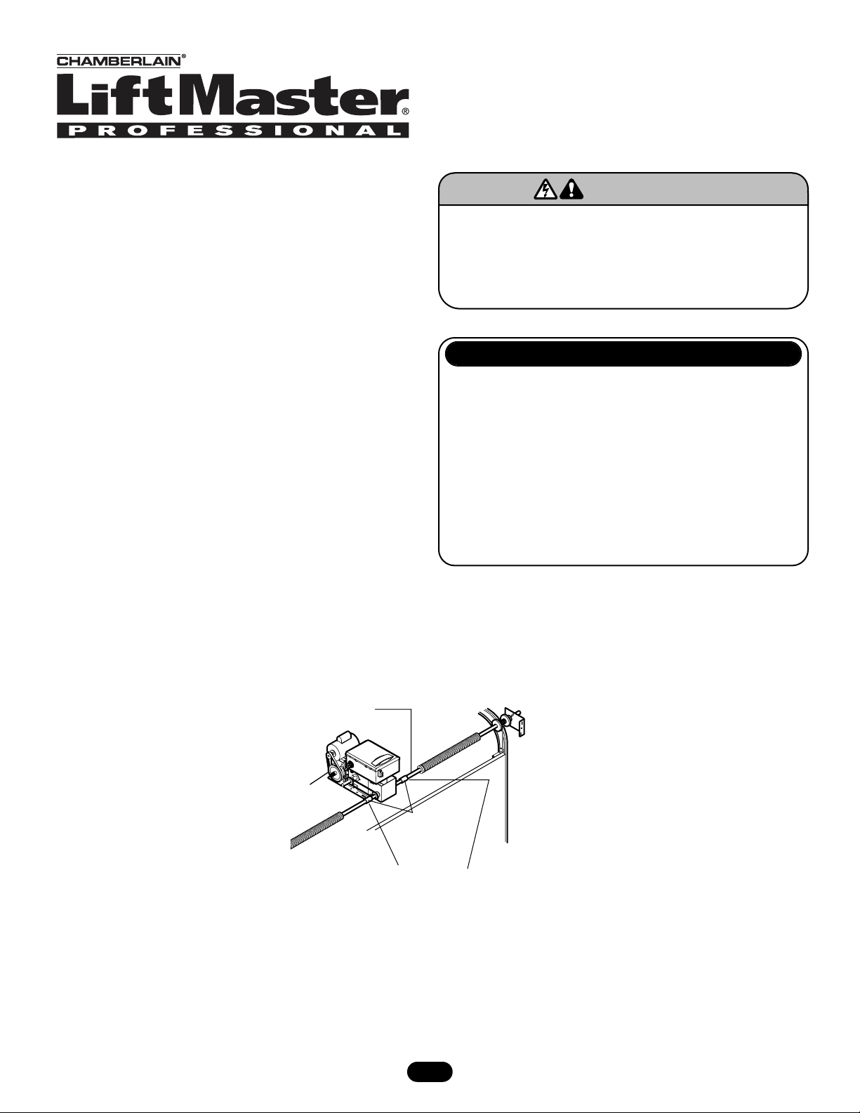
NOTE: View shown as if looking through wall.
Door Shaft
Shaft Couplings
(not provided)
When performing this modification
the door should be closed and no
tension on the doorshaft
Page 2
© 2005, The Chamberlain Group, Inc.
01-12497B All Rights Reserved Printed in Mexico
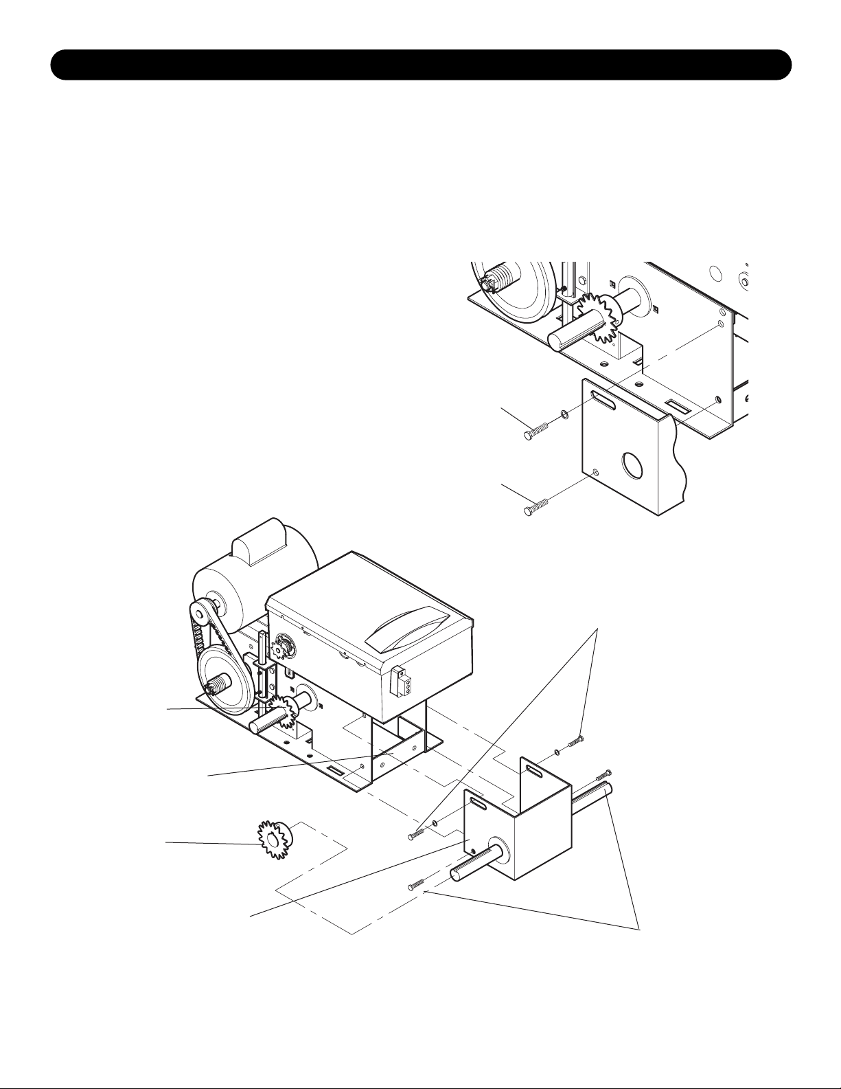
1. Remove (2) frame connecting bracket bolts, be sure to leave
bracket in same position (Figure 2).
2. Position center mount bracket assembly as shown (Figure 3).
Install (2) 3/8-16 x 1" hex head bolts and (2) 3/8-16 serrated
flange nuts to connect bracket, frame and connecting bracket
(be sure the connecting bracket stays in the same position it
was in when the bolts were removed in step one). Do not fully
tighten the bolts at this time (Figure 2).
3. Install (2) 3/8-16 x 1" hex head bolts, (2) flat washers and (2)
3/8-16 serrated flange nuts through the slotted holes in the
bracket assembly. Position flat washers over the slots. Do not
fully tighten the bolts at this time (Figure 2).
4. Install and align sprockets A and B. Install chain, pivot bracket
assembly to tighten chain (allow some slack) and tighten bolts.
5. Install operator into door shaft using shaft couplers (not
provided) and provide suitable back hangs for the power head.
6. Extend the disconnect chain with the chain and key rings
provided. Route the chain through the eye bolts taking care not
to interfere with the door or operator mechanism. It may be
necessary to add a helper spring somewhere in the disconnect
chain to prevent the chain weight from disconnecting the
release mechanism.
FIGURE 2
FIGURE 3
INSTALLATION INSTRUCTIONS
See Step 3
See Step 2
Sprocket “A”
Sprocket “B”
Frame Connecting
Bracket (See Step 1)
Center Mount
Bracket Assembly
Hardware Stack, (1) 3/8-16 x 1"
Hex Head Bolt, (1) 3/8" Flatwasher
and (1) 3/8-16 Serrated Flange Nut.
(Typical on Both Sides)
Hardware Stack, (1) 3/8-16 x 1"
Hex Head Bolt, (1) 3/8-16
Serrated Flange Nut.
(Typical on Both Sides)
 Loading...