

Page 1
APPLICATION
Replaces operator hand chain wheel and chain with hook and
eyelet connection for extended floor level hand crank. Used on
Model H, DH and GH operators. Must be factory installed.
HAND CRANK MODIFICATION
Assembly Instructions
656202 OR 659201
(Models H & DH OR Model GH)
INSTRUCTIONS
1. A section of 1/2" rigid electrical conduit must be furnished by
the installer. The length of this pipe will vary with each
installation and should be determined so as to fix the winding
brace handle at chest height when connected to the door
operator.
2. Drill a 1/4" diameter hole through each end of the rigid pipe,
1/2" from the end.
3. Attach the eye and winding brace to the ends of the pipe with
the screws and nuts provided (Figure 2).
NOTE: If an extended Hand Crank Kit was requested refer to
instructions on back page before going onto next step.
4. Connect the hand crank hook shaft in the same manner that the
eye is connected to the rigid pipe.
CRANK OPERATION
1. Pull the door operator disconnect chain down and lock in place
on the chain retaining bracket (Refer to operator owner’s
manual).
2. Slip the eye end of the hand crank over the hook on the
extended shaft of the operator and rotate the handle to
manually raise or lower the door (Figure 3).
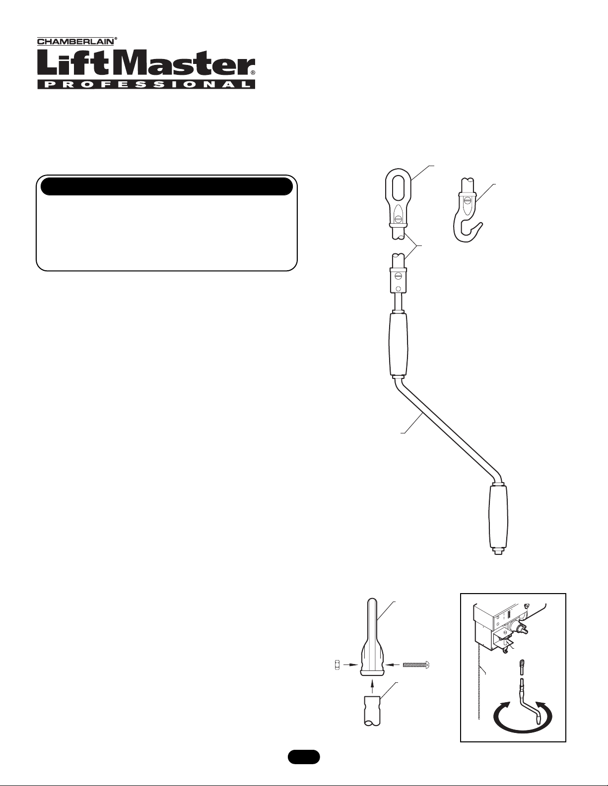
FIGURE 1
DESCRIPTION QTY
Eye #3 1
Winding Brace #9 1
Hook #1 1
PACKING LIST
FIGURE 2
FIGURE 3
1
Eye
Hook
1/2" Pipe
(Not Provided)
Winding Brace
1/4" Nut
Eye
1/4" Screw
1/2" Pipe
Hand Crank
Hook Shaft
Disconnect
Chain
Page 2

Hook Shaft
Hex Bolt 5/16-18 x 2"
Shaft Coupling
Extension Shaft 30"
Hook (See Step 4)
Lock Nut 5/16"
© 2005, The Chamberlain Group, Inc.
01-13035B All Rights Reserved Printed in Mexico
(OPTIONAL) HAND CRANK EXTENSION
1. Remove the 5/16" hex bolt and nut from the shaft coupling not
holding the extension shaft in place and set of to the the side.
2. Slide the shaft coupling over the hook shaft and secure in place
with the hardware previously removed.
3. Refer to step four on front page to complete installation.
FIGURE 4
 Loading...