

Page 1

APPLICATION
Manual Hoist Modification for use with model T or GT operators.
• 655209 for 1/3 & 1/2 HP trolley operators with #48 drive chain
• 6552091 for 3/4 & 1 HP trolley operators with #48 drive chain
• 6552092 for GT operators with #41 drive chain
Modification provides hand chain operation for manually
opening/closing the door as follows:
1. A chain wheel is coupled to a cross header shaft which in turn
is coupled to the front idler of the trolley.
2. The front idler pulley is replaced by a #48 sprocket thus
allowing the chain wheel to drive the door arm.
QTY
1
1
2
1
1
1
1
1
1
1
1
1
1
1
1
1
1
1
DESCRIPTION
Instructions
Chain Retaining Bracket
Bearing Assembly
Sprocket, 48B14 1" Bore
Sprocket, 50B35 1" Bore and 5/16" Set Screws
Hand Chain
Chain (47 Pitches) #41
Master Link #41
Chain (49 Pitches) #48
Master Link #48
Chain Package #50
Front Idler Assembly for #41 Chain
Manual Hoist Housing
Brake Cable Release Kit
Roll Pin 3/16" x 3"
Roll Pin 1/4" x 1-3/4"
Roll Pin 5/16" x 3"
Front Idler Assembly For #48 Chain
PART #
10-10893
12-11438
15-48B14LXX
15-50B35LGH
19-10929-25
*19-41047
*19-41ML
**19-48049
**19-48ML
19-50106M
75-11503
75-11973
75-11459
86-RP06-300
86-RP08-112
86-RP10-300
75-11502
Manual Hoist Modification
Used For Trolley Operators
655209 (1/3 & 1/2 HP trolley operators)
6552091 (3/4 & 1 HP trolley operators)
6552092 (GT operators)
PREPARATION
1. Door size to be indicated at time of order. If the door size
specified is 16 feet or taller a sash chain and key ring package
will also be included with packing list.
2. A cross header shaft is required for installation of this manual
hoist (not provided).
This shaft is available and will be provided if specified at time
of order.
1" cold rolled steel shaft 12 ft. long, for doors up to 20 ft. wide.
1" cold rolled steel shaft 20 ft. long, for doors over 20 ft. wide.
* Used on #41 Drive Chain only.
** Used on #48 Drive Chain only.
PACKING LIST
3. Hand chain length is twice the door height less 3 feet. Ensure
the proper length of chain has been provided.
4. If the manual hoist is being added to pre-installed operator, it
will be necessary to move the operator and track assembly
back (into the garage) approximately 6" to allow for installation
of the new front drive assembly.
1
Page 2
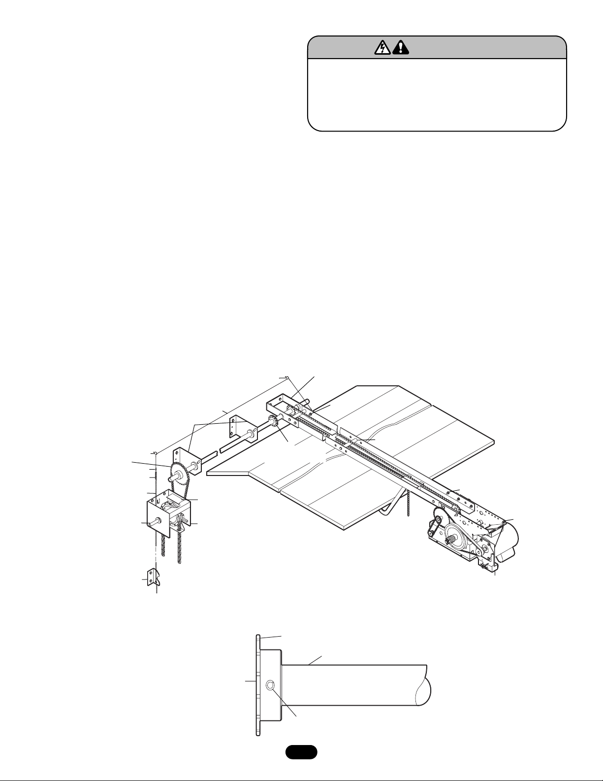
FIGURE 1
FIGURE 2
2
1. Disconnect power to operator.
2. Existing Installation: Using proper temporary support for the
operator and track assembly, disassemble the existing front
bracket and idler assembly from the track end (Refer to
owner’s manual if necessary).
New Installation: Assemble the trolley operator according to
the owner’s manual. Use the new front bracket and idler
provided.
3. The chain hoist can be installed on the left or right side of the
door. Determine which side the chain hoist will be mounted on
and install the front idler assembly with the sprocket coupling
facing in the desired direction. Be sure to install a track spacer
at the end of the track.
4. Using the chain and master link provided, lengthen the existing
chain provided with the operator. Add/Remove links as required
for proper tension of the drive chain. Refer to the owner’s
manual for the proper tension value.
5. Position and mount the operator/track assembly as indicated in
the owner's manual.
NOTE: The front bracket will not pivot as shown in the manual so
temporary support of the operator will be required.
6. If you supply your own shaft you will need a length of 1" solid
shaft (ideally cold rolled steel). The approximate length of this
shaft should be one-half the door width plus 2 feet. Determine
the chain hoist location and cut the shaft to the desired length.
To prevent possible SERIOUS INJURY or DEATH, disconnect
electric power to operator BEFORE installing.
ALL installations and electrical connections MUST be made by
a qualified individual.
WARNING
WARNING
7. Install the 48B14 sprocket on one end of the shaft, (Figure 2).
Align sprocket flush with end of shaft, drill a 1/4" diameter hole
through sprocket hub and shaft. Secure using 1/4" x 1-3/4"
rollpin. Slide the two shaft support bearings onto the shaft.
Drill and pin the 40 tooth drive sprocket in desired location on
the opposite end of the shaft.
8. Supporting the far end of the shaft, butt together the two
48B14 sprockets and connect using the #41 chain provided.
9. Position the bearings on shaft so that one bearing is at the mid
point and the other as close to the 40 tooth sprocket as
possible. With the shaft level and using suitable hardware,
secure the bearings.
10.Vertically align the hand chain sprocket with the 40 tooth drive
sprocket. With the chain in place, and using suitable hardware,
secure the hoist housing. Align and secure the hand chain
retaining bracket.
Driven Sprocket #50B35
Cable Clamps (2) *
Brake Release Chain*
Drive Sprocket
(Can Be on Either Side)
Chain Retaining Bracket
Eyelet*
Spring*
Brake Release Cable*
Bearings
Interlock Switch
(Wired to Operator)
See Instructions
Manual Hoist Housing
* Items are Provided Only if Operator is Equipped with Solenoid Brake.
Eyelet*
Chain and Sprocket
Coupling
48B14 Sprocket 1" Bore
Front Bracket and Idler Assembly
(Can be Installed for Right or Left
Hand Drive, Left Hand Shown)
Eye Bolt*
Track Spacer*
Eye Bolt*
Eye Bolt*
Solenoid Brake
(When Required)
1" Diameter Shaft
Be Sure Shaft is Flush With
Sprocket. Do Not Let Shaft
Protrude Beyond Sprocket.
Drill 1/4" Hole - Pin With 1/4"x1-3/4" Roll Pin
Page 3

Manual Hoist Model GT operators are equipped with a power train
disconnect mechanism and an interlock switch to disable the
electrical operation of the operator. A disconnect cable, used to
activate the disconnect, must be installed. Follow the directions
below referring to the illustrations as necessary.
1. Install (2) eye bolts in the track at the locations (Figure 1). It is
not necessary to install the third eye bolt.
3. Install the two (2) eyelets on the jamb.
4. Attach one end of the disconnect cable to the end of the
disconnect lever (Figure 4).
5. Install the spring and key ring assembly to the length of
disconnect chain.
6. Run the cable through the eye bolts and the eyelets and loosely
fasten to the spring with the two (2) cable clamps.
7. Adjust the cable to insure that the disconnect lever actuates
when the disconnect chain is pulled.
MODEL T OPERATORS WITH A SOLENOID BRAKE
MODEL GT OPERATORS
If the operator is equipped with a solenoid brake it will be
necessary to install a release cable.
1. Install the (3) eye bolts in the approximate locations (Figure 3).
Drill a hole in the operator frame.
2. Install the two (2) eyelets on the jamb.
3. Thread the brake release cable through the holes in the brake
plate and the release plate (Figure 3). Slide the #8 flat washer
on and fasten the cable stop sleeve on the end.
4. Install the spring and key ring assembly to the length of
disconnect chain.
5. Run the cable through the eye bolts and the eyelets and loosely
fasten to the chain with the two (2) cable clamps.
6. Adjust the cable so that the brake releases when the brake
release chain is engaged. Ensure that the brake functions
normally at all other times.
FIGURE 3
FIGURE 4
3
Washer
Cable
Sleeve
Brake
Release
Cable
Brake Release
Lever
Solenoid Brake
(When Required)
Eye Bolt
Disconnect Cable
Disconnect Lever
Page 4

© 2005, The Chamberlain Group, Inc.
01-11241E All Rights Reserved Printed in Mexico
Wiring must be in compliance with local building and electrical
codes. Using 16 gauge wire, wire the interlock switch located on
the hand chain mechanism to the operator terminal block.
Refer to the wiring diagram provided on the inside cover of the
operator for proper wire connections.
Remove the factory provided jumper between terminals in the
electrical box. Terminals 4 and 5 in mechanical operators, and
terminals 2 and 3 in logic operators. If other external interlock
devices are present connect interlocks in series.
INTERLOCK SWITCH WIRING
To prevent possible SERIOUS INJURY from moving parts
when hand chain is in use, interlock MUST be installed.
WARNING
WARNING
 Loading...