

Life Fitness X5/ X5i Operation Manual

X5/X5i CROSS-TRAINER
ASSEMBLY & OPERATION MANUAL
lifefitness.com
CONGRATULATIONS...
AND WELCOME TO THE WORLD OF LIFE FITNESS
AND THE
The following operation and assembly procedures have been prepared to make the
set-up and operation of this Cross-Trainer as quick and easy as possible.
Please take special note of the following important points prior to choosing
a location and beginning assembly of the Cross-Trainer
LIFE FITNESS X5 AND X5I CROSS-TRAINER.
BEFORE ASSEMBLING CROSS-TRAINER
DO NOT locate the cross-trainer outdoors, near swimming pools, or in areas
of high humidity.
DO Make sure the sides, front and back of the cross-trainer maintain a minimum
clearance of 8 inches (20 cm) from the nearest obstruction.
DO verify the contents of the delivery carton against the accompanying parts listing
prior to setting the cartons and shipping material aside. If any parts are missing,
contact Life Fitness Customer Support Services at the number listed on page 26 of
this assembly instruction booklet. Save the shipping cartons in case of return.
DO read the entire Operation Manual prior to attempting to operate this machine, as
this is essential for proper use. The Manual explains how to properly use the crosstrainer and helps you to design a workout tailored to your personal fitness goals.
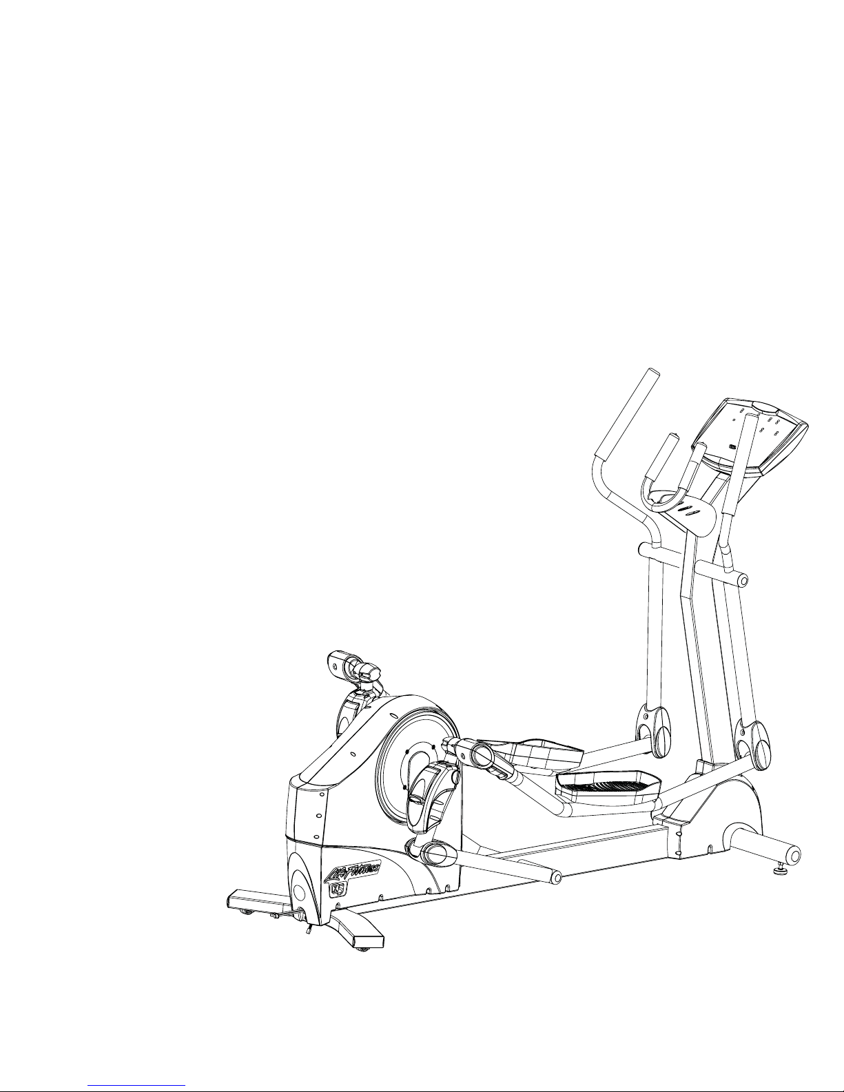
This Operation Manual describes the
functions of the Life Fitness
X-Series X5 & X5i Cross-Trainers
Statement of Purpose
This Cross-Trainer is a home
exercise machine that combines
low-impact elliptical pedaling with
push/pull arm motion to provide an
efficient, effective total body workout.
Product-specific features for each
model are described in this manual
under Specifications.
Warning: Injuries to health may
result from incorrect or excessive
training. See the Correct Usage
section on page 17.
Life Fitness STRONGLY
recommends consulting your doctor
before undertaking any exercise
program, particularly if the user has a
family history of high blood pressure
or heart disease, is over the age of
45, smokes, has high cholesterol, is
obese, or has not exercised regularly
in the past year.
For your safety, before using this product, read the ENTIRE Operation Manual
and ALL Assembly Instructions. They describe equipment setup
and include instructions on how to use your equipment correctly and safely.
Class H (Home): Domestic use.
CAUTION: Any changes or modifications to this equipment could
void the product warranty.
An authorized service representative must perform any service, other than
cleaning or user maintenance. There are no user serviceable parts.
© 2000 Life Fitness, a division of Brunswick Corporation. All rights reserved. Life Fitness,
and Heart Rate Zone Training are registered trademarks and Go System-QuickStart
Select Stride, Extreme HR, MagnaForce, EZ Resistance, Intelli, and Sport Training are
trademarks of Brunswick Corporation. Polar is a registered trademark of Polar Electro, Inc.
Any use of these trademarks, without the express written consent of Life Fitness or the
corresponding companies is forbidden.
,
If, at any time while exercising, you
experience faintness, dizziness, pain,
or shortness of breath, stop
immediately.
Life Fitness conseille VIVEMENT de
consulter un médecin pour suivre un
examen médical complet avant de se
lancer dans un programme dexercice.
Ceci concerne surtout les utilisateurs
avec des antécédents familiaux de
tension élevée ou daffections
cardiaques, les personnes de plus
de 45 ans, les fumeurs et les obèses,
ainsi que tous ceux qui ont un taux
élevé de cholestérol ou qui nont pas
fait dexercice régulièrement depuis
un an.
Si, à tout moment pendant lexercice,
lutilisateur ressent un malaise, un
étourdissement ou une douleur, ou
sil se trouve à bout de souffle, il doit
sarrêter immédiatement.
2

TABLE OF CONTENTS
Section Description . . . . . . . . . . . . . . . . . . . . . . . . . . . . . . . . . . . . . . . . . . . . . . . . . . . . . . . . Page
1. GETTING STARTED . . . . . . . . . . . . . . . . . . . . . . . . . . . . . . . . . . . . . . . . . . . . . . . . . . . . . . . . . . . . . . . . . . . 4-11
1.1 Important Safety Instructions . . . . . . . . . . . . . . . . . . . . . . . . . . . . . . . . . . . . . . . . . . . . . . . . . . . . . . . . . . . . . . . . . . . . . . . . 4
1.2 Parts List . . . . . . . . . . . . . . . . . . . . . . . . . . . . . . . . . . . . . . . . . . . . . . . . . . . . . . . . . . . . . . . . . . . . . . . . . . . . . . . . . . . . . . 5
1.3 Parts Description . . . . . . . . . . . . . . . . . . . . . . . . . . . . . . . . . . . . . . . . . . . . . . . . . . . . . . . . . . . . . . . . . . . . . . . . . . . . . . . . 5
1.4 Setup . . . . . . . . . . . . . . . . . . . . . . . . . . . . . . . . . . . . . . . . . . . . . . . . . . . . . . . . . . . . . . . . . . . . . . . . . . . . . . . . . . . . . . . . . 6
1.5 How To Stabilize The Life Fitness Cross-Trainer . . . . . . . . . . . . . . . . . . . . . . . . . . . . . . . . . . . . . . . . . . . . . . . . . . . . . . . . . 11
AssemblyOperationsMisc.
1.6 Plugging in the Cross-Trainer . . . . . . . . . . . . . . . . . . . . . . . . . . . . . . . . . . . . . . . . . . . . . . . . . . . . . . . . . . . . . . . . . . . . . . . 11
2. THE DISPLAY CONSOLE . . . . . . . . . . . . . . . . . . . . . . . . . . . . . . . . . . . . . . . . . . . . . . . . . . . . . . . . . . . . . . . 12-13
2.1 Display Console Overview . . . . . . . . . . . . . . . . . . . . . . . . . . . . . . . . . . . . . . . . . . . . . . . . . . . . . . . . . . . . . . . . . . . . . . . . . 12
2.2 X5 Display Console Descriptions . . . . . . . . . . . . . . . . . . . . . . . . . . . . . . . . . . . . . . . . . . . . . . . . . . . . . . . . . . . . . . . . . . . . . 12
2.3 X5i Display Console Descriptions . . . . . . . . . . . . . . . . . . . . . . . . . . . . . . . . . . . . . . . . . . . . . . . . . . . . . . . . . . . . . . . . . . . . 13
3. ACCESSORIES . . . . . . . . . . . . . . . . . . . . . . . . . . . . . . . . . . . . . . . . . . . . . . . . . . . . . . . . . . . . . . . . . . . . . . . 14
3.1 Reading Rack . . . . . . . . . . . . . . . . . . . . . . . . . . . . . . . . . . . . . . . . . . . . . . . . . . . . . . . . . . . . . . . . . . . . . . . . . . . . . . . . . . . 14
3.2 Accessory Trays . . . . . . . . . . . . . . . . . . . . . . . . . . . . . . . . . . . . . . . . . . . . . . . . . . . . . . . . . . . . . . . . . . . . . . . . . . . . . . . . . 14
4. SELECTSTRIDE. . . . . . . . . . . . . . . . . . . . . . . . . . . . . . . . . . . . . . . . . . . . . . . . . . . . . . . . . . . . . . . . . . . . . . 14-15
4.1 Description & Benefits . . . . . . . . . . . . . . . . . . . . . . . . . . . . . . . . . . . . . . . . . . . . . . . . . . . . . . . . . . . . . . . . . . . . . . . . . . . . . 14
4.2 Adjusting the SelectStride
4.3 Stride Descriptions. . . . . . . . . . . . . . . . . . . . . . . . . . . . . . . . . . . . . . . . . . . . . . . . . . . . . . . . . . . . . . . . . . . . . . . . . . . . . . . . 15
5. HEART RATE ZONE TRAINING EXERCISE . . . . . . . . . . . . . . . . . . . . . . . . . . . . . . . . . . . . . . . . . . . . . . . . . 16
5.1 Why Heart Rate Zone Training Exercise? . . . . . . . . . . . . . . . . . . . . . . . . . . . . . . . . . . . . . . . . . . . . . . . . . . . . . . . . . . . . . . 16
5.2 Heart Rate Monitoring, The Heart Rate Chest Strap . . . . . . . . . . . . . . . . . . . . . . . . . . . . . . . . . . . . . . . . . . . . . . . . . . . . . . 17
6. CORRECT USAGE . . . . . . . . . . . . . . . . . . . . . . . . . . . . . . . . . . . . . . . . . . . . . . . . . . . . . . . . . . . . . . . . . . . . 17-18
6.1 Lower Body vs. Total Body . . . . . . . . . . . . . . . . . . . . . . . . . . . . . . . . . . . . . . . . . . . . . . . . . . . . . . . . . . . . . . . . . . . . . . . . . 17
6.2 Biomechanical Guidelines . . . . . . . . . . . . . . . . . . . . . . . . . . . . . . . . . . . . . . . . . . . . . . . . . . . . . . . . . . . . . . . . . . . . . . . . . . 17
6.2.1 General . . . . . . . . . . . . . . . . . . . . . . . . . . . . . . . . . . . . . . . . . . . . . . . . . . . . . . . . . . . . . . . . . . . . . . . . . . . . . . . . . . . . . . . 17
6.2.2 Forward Motion Lower Body . . . . . . . . . . . . . . . . . . . . . . . . . . . . . . . . . . . . . . . . . . . . . . . . . . . . . . . . . . . . . . . . . . . . . . 17
6.2.3 Forward Motion Total Body . . . . . . . . . . . . . . . . . . . . . . . . . . . . . . . . . . . . . . . . . . . . . . . . . . . . . . . . . . . . . . . . . . . . . . . . 18
6.2.4 Reverse Motion Lower Body . . . . . . . . . . . . . . . . . . . . . . . . . . . . . . . . . . . . . . . . . . . . . . . . . . . . . . . . . . . . . . . . . . . . . . 18
6.2.5 Reverse Motion Total Body . . . . . . . . . . . . . . . . . . . . . . . . . . . . . . . . . . . . . . . . . . . . . . . . . . . . . . . . . . . . . . . . . . . . . . . 18
7. THE WORKOUTS . . . . . . . . . . . . . . . . . . . . . . . . . . . . . . . . . . . . . . . . . . . . . . . . . . . . . . . . . . . . . . . . . . . . . 18-24
7.1 Workout Descriptions . . . . . . . . . . . . . . . . . . . . . . . . . . . . . . . . . . . . . . . . . . . . . . . . . . . . . . . . . . . . . . . . . . . . . . . . . . . . . 18
7.1.1 Manual/QuickStart
7.1.2 Zone Training . . . . . . . . . . . . . . . . . . . . . . . . . . . . . . . . . . . . . . . . . . . . . . . . . . . . . . . . . . . . . . . . . . . . . . . . . . . . . . . . . . . 18
7.1.3 Fat Burn . . . . . . . . . . . . . . . . . . . . . . . . . . . . . . . . . . . . . . . . . . . . . . . . . . . . . . . . . . . . . . . . . . . . . . . . . . . . . . . . . . . . . . . 18
7.1.4 Cardio . . . . . . . . . . . . . . . . . . . . . . . . . . . . . . . . . . . . . . . . . . . . . . . . . . . . . . . . . . . . . . . . . . . . . . . . . . . . . . . . . . . . . . . . 19
7.1.5 Heart Rate Hill And Heart Rate Interval Workouts . . . . . . . . . . . . . . . . . . . . . . . . . . . . . . . . . . . . . . . . . . . . . . . . . . . . . . . . 19
7.1.6 Extreme HR Workout . . . . . . . . . . . . . . . . . . . . . . . . . . . . . . . . . . . . . . . . . . . . . . . . . . . . . . . . . . . . . . . . . . . . . . . . . . . . . . 20
7.1.7 Sport Training . . . . . . . . . . . . . . . . . . . . . . . . . . . . . . . . . . . . . . . . . . . . . . . . . . . . . . . . . . . . . . . . . . . . . . . . . . . . . . . . . . . 20
7.1.8 Random . . . . . . . . . . . . . . . . . . . . . . . . . . . . . . . . . . . . . . . . . . . . . . . . . . . . . . . . . . . . . . . . . . . . . . . . . . . . . . . . . . . . . . . 20
7.1.9 Manual . . . . . . . . . . . . . . . . . . . . . . . . . . . . . . . . . . . . . . . . . . . . . . . . . . . . . . . . . . . . . . . . . . . . . . . . . . . . . . . . . . . . . . . . 20
7.1.10 EZ Resistance . . . . . . . . . . . . . . . . . . . . . . . . . . . . . . . . . . . . . . . . . . . . . . . . . . . . . . . . . . . . . . . . . . . . . . . . . . . . . . . . . . 20
7.1.11 Cool-Down . . . . . . . . . . . . . . . . . . . . . . . . . . . . . . . . . . . . . . . . . . . . . . . . . . . . . . . . . . . . . . . . . . . . . . . . . . . . . . . . . . . . . 20
7.1.12 Hill . . . . . . . . . . . . . . . . . . . . . . . . . . . . . . . . . . . . . . . . . . . . . . . . . . . . . . . . . . . . . . . . . . . . . . . . . . . . . . . . . . . . . . . . . . . 21
7.1.13 Cross-Train Aerobic . . . . . . . . . . . . . . . . . . . . . . . . . . . . . . . . . . . . . . . . . . . . . . . . . . . . . . . . . . . . . . . . . . . . . . . . . . . . . . 21
7.1.14 Cross-Train Reverse . . . . . . . . . . . . . . . . . . . . . . . . . . . . . . . . . . . . . . . . . . . . . . . . . . . . . . . . . . . . . . . . . . . . . . . . . . . . . . 21
7.2 Using the Workouts (Charts) . . . . . . . . . . . . . . . . . . . . . . . . . . . . . . . . . . . . . . . . . . . . . . . . . . . . . . . . . . . . . . . . . . . . . . . . 22
7.3.1 My workouts Introduction . . . . . . . . . . . . . . . . . . . . . . . . . . . . . . . . . . . . . . . . . . . . . . . . . . . . . . . . . . . . . . . . . . . . . . . . . 23
7.3.2 User Statistics . . . . . . . . . . . . . . . . . . . . . . . . . . . . . . . . . . . . . . . . . . . . . . . . . . . . . . . . . . . . . . . . . . . . . . . . . . . . . . . . . . . 23
7.3.3 Programmable Parameters . . . . . . . . . . . . . . . . . . . . . . . . . . . . . . . . . . . . . . . . . . . . . . . . . . . . . . . . . . . . . . . . . . . . . . . . . 23
7.3.4 Name, Programming . . . . . . . . . . . . . . . . . . . . . . . . . . . . . . . . . . . . . . . . . . . . . . . . . . . . . . . . . . . . . . . . . . . . . . . . . . . . . . 23
7.3.5 Workout, Programming . . . . . . . . . . . . . . . . . . . . . . . . . . . . . . . . . . . . . . . . . . . . . . . . . . . . . . . . . . . . . . . . . . . . . . . . . . . . 24
7.3.6 Statistics, Display . . . . . . . . . . . . . . . . . . . . . . . . . . . . . . . . . . . . . . . . . . . . . . . . . . . . . . . . . . . . . . . . . . . . . . . . . . . . . . . . 24
8. USER MENU . . . . . . . . . . . . . . . . . . . . . . . . . . . . . . . . . . . . . . . . . . . . . . . . . . . . . . . . . . . . . . . . . . . . . . . . . 24
8.1 Overview . . . . . . . . . . . . . . . . . . . . . . . . . . . . . . . . . . . . . . . . . . . . . . . . . . . . . . . . . . . . . . . . . . . . . . . . . . . . . . . . . . . . . . 24
8.2 Entering user menu . . . . . . . . . . . . . . . . . . . . . . . . . . . . . . . . . . . . . . . . . . . . . . . . . . . . . . . . . . . . . . . . . . . . . . . . . . . . . . 24
8.3 Description of User Menu Items . . . . . . . . . . . . . . . . . . . . . . . . . . . . . . . . . . . . . . . . . . . . . . . . . . . . . . . . . . . . . . . . . . . . . 24
9. SERVICE AND TECHNICAL DATA . . . . . . . . . . . . . . . . . . . . . . . . . . . . . . . . . . . . . . . . . . . . . . . . . . . . . . . . . 25-27
9.1 Preventive Maintenance Tips . . . . . . . . . . . . . . . . . . . . . . . . . . . . . . . . . . . . . . . . . . . . . . . . . . . . . . . . . . . . . . . . . . . . . . . . 25
9.2 Troubleshooting The Heart Rate Chest Strap . . . . . . . . . . . . . . . . . . . . . . . . . . . . . . . . . . . . . . . . . . . . . . . . . . . . . . . . . . . 25
9.3 How To Obtain Product Service . . . . . . . . . . . . . . . . . . . . . . . . . . . . . . . . . . . . . . . . . . . . . . . . . . . . . . . . . . . . . . . . . . . . . . 26
10. SPECIFICATIONS FOR X5I & X5 . . . . . . . . . . . . . . . . . . . . . . . . . . . . . . . . . . . . . . . . . . . . . . . . . . . . . . . . . . 27
. . . . . . . . . . . . . . . . . . . . . . . . . . . . . . . . . . . . . . . . . . . . . . . . . . . . . . . . . . . . . . . . . . . . . . . . . . 14-15
. . . . . . . . . . . . . . . . . . . . . . . . . . . . . . . . . . . . . . . . . . . . . . . . . . . . . . . . . . . . . . . . . . . . . . . . . . . . . . . 18
3
1. GETTING STAR TED
1.1 IMPORTANT SAFETY INSTRUCTIONS
WARNING: Safety of the Cross-Trainer can be maintained only if it is examined regularly for damage and wear. Keep this product
out of use until defective parts are repaired or replaced. Pay special attention to the moving linkages
and connection points. See Preventive Maintenance section for complete details.
To reduce the risk of electrical shock, always unplug this Life Fitness product before cleaning or maintenance.
To reduce the risk of burns, fire, electric shock or injury, always connect each product to a properly grounded electrical outlet.
Never operate a Life Fitness product if it has a damaged power cord or electrical plug, or if it has been dropped, damaged,
or even partially immersed in water. Contact Life Fitness Customer Support Services.
Keep the power cord away from heated surfaces. Do not pull the equipment by the power cord or use the cord as a handle.
Do not run the power cord on the floor under or alongside of the Cross-Trainer.
Always follow the console instructions for proper operation.
Close supervision is necessary when Cross-Trainer is used by children, or disabled persons.
Do not use this product outdoors, near swimming pools or in areas of high humidity.
Never insert objects into any opening in this product. If an object should drop inside, turn off
the power, unplug the power cord from the outlet and carefully retrieve it. If the item cannot
be reached, contact Life Fitness Customer Support Services. Refer to page 26 for correct
contact information.
Never place liquids of any type directly on the unit, except in the optional accessory tray
or holder. Containers with lids are recommended.
Wear shoes with rubber or high-traction soles. Do not use shoes with heels, leather soles,
cleats or spikes. Make sure no stones are embedded in the soles.
Keep all loose clothing, shoelaces and towels away from moving parts.
Keep the Life Fitness product away from
walls and clear of any obstructions and
furniture. Ensure that there is at least one
foot clearance in front of the Cross-Trainer.
Use caution when mounting or dismounting
the Cross-Trainer. Use the stationary
handlebar whenever additional stability
is required. While exercising, always
hold onto the user arms or
stationary handlebar.
Never operate the Cross-Trainer
facing backwards.
SAVE THESE INSTRUCTIONS
FOR FUTURE REFERENCE
4
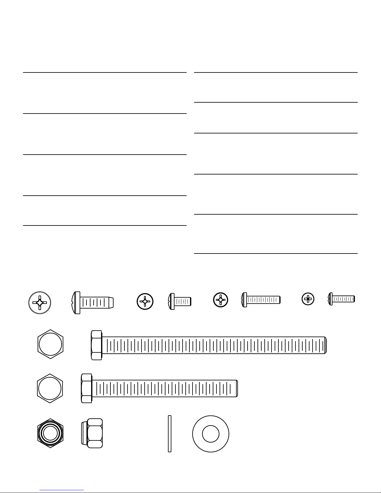
1.2 PARTS LIST The following parts are illustrated in actual size.
0. Accessory Bracket Fastener Qty: 2
1/4"-20 x 3/4" LONG 3234101
1. Phillips Pan Head Screw Clevis Cover & Front Shroud
Fastener
10-32 x 3/8" LONG 3223401
Qty: 12
2. Electronics Console Mounting Fastener
Qty: 4
8-18 x 3/4" LONG Phillips Pan PLT ST 3225905
3. Upright Cap & Front Shroud Mounting Fastener
Qty: 5
6-20 x 1/2" LONG Phillips Pan PLT ST 3226003
4. Upright Mounting Bolt Qty: 2
3/8 16 x 5" LONG 3223301
5. Front Clevis/Pedal Lever & Upright Mounting BoltQty: 6
3/8 16 x 3-1/4" LONG 3223310
6. Nylock Nut High Profile Qty: 8
3/8 - 16 3102802
7. 3/8" Washer Qty: 12
3102514
Not illustrated Plastic Upright Cap Black
Qty: 1
Cap, Tube 2 x 4 Custom 6961001
Not illustrated Front upright shroud Gray
6997201 Left (1)
6997301 Right (1)
Not illustrated Cover, Clevis 1.75" Top/Bottom Black
1.3 PARTS DESCRIPTION
0. 1. 2. 3.
4.
5.
6914901 Top (2)
6915001 Bottom (2)
6. 7.
5
1.4 SETUP
Tools required: Socket set, Phillips Screwdriver, 9/16" open end wrench
Please read instructions carefully before assembly. Be sure to assemble the unit where it is to be used.
STEP 1
Remove the machine from packaging. Carefully lay out and count each part before assembly. Refer to the parts list on page 5 of this
manual.
A
5
6
7
7
B
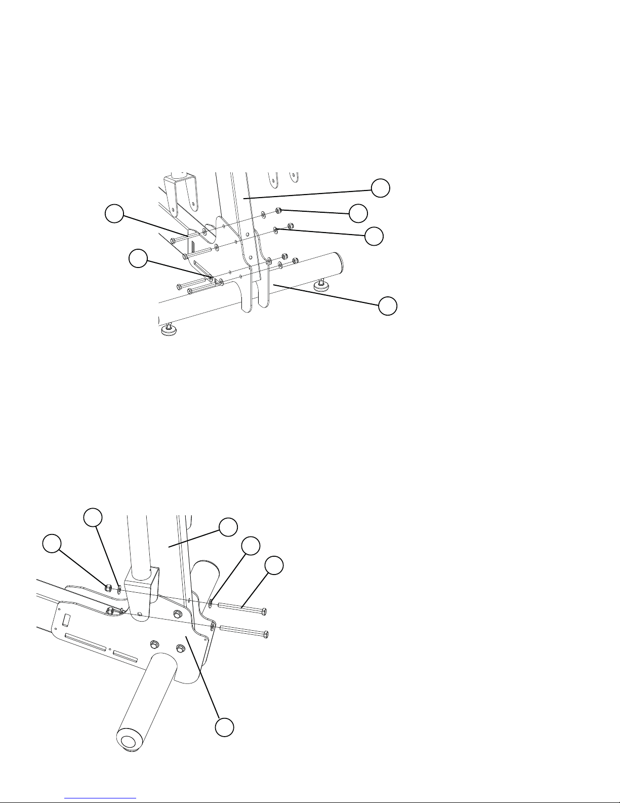
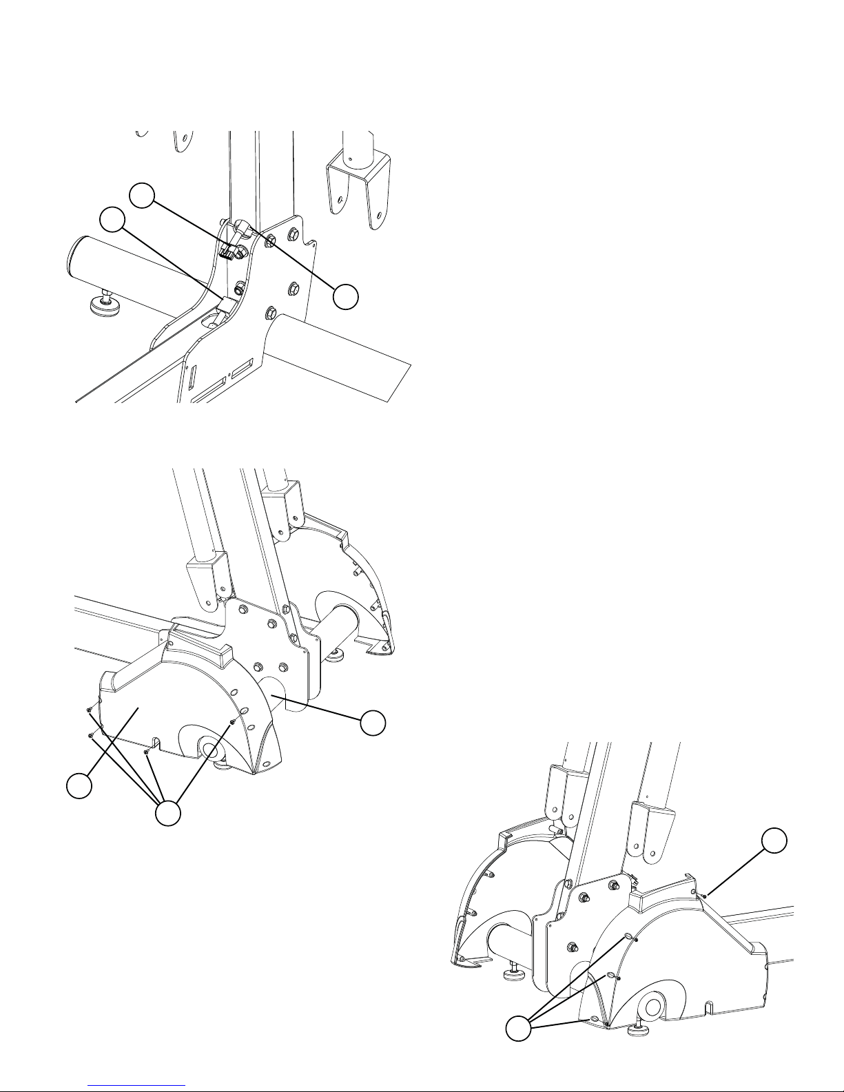
STEP 2
Assemble the upright tube assembly to the base frame:
NOTE: This step could require two people.
1. Position the upright tube assembly (A) between the plates on the front of the base frame (B).
2. Line up the holes on the plates (B) with the holes on the upright tube assembly (A).
3. Connect the upright tube assembly (A) to the base frame (B) using four (#5) 3-1/4" bolts, eight (#7) washers (4 on each side) and
four (#6) high profile nylock nuts. DO NOT FULLY TIGHTEN AT THIS POINT.
CAUTION: The wire harness may obstruct the connecting holes. If this happens, gently pull on the end of the wire
harness at the top of the upright tube assembly (A) to clear the hole. Do not force the bolt through the hole if the wire
harness is obstructing the bolt, as damage to the wire harness may result.
7
6
A
7
4
4. Insert two (#4) 5 " bolts and two (#7) washers into the backside
of the connector joint on the base frame (B). Connect with two
(#7) washers and two(#6) high profile nylon lock nuts. Start
each bolt, and then tighten with a 9/16 " socket wrench.
5. Tighten all six bolts with a 9/16 " socket wrench.
B
6
1.4 SETUP (CONTINUED)
C
D
STEP 3
1. Connect the upper wire harness (C) to the lower
wire harness (D). Insert connected plugs of the
wire harnesses into wiring hole on upright tube
assembly (A).
A
STEP 4
1. Attach front shroud (A) to base-frame (B) using
eight (#1) phillips pan head screws (4 on each
side). Using a phillips screwdriver, secure the
shrouds to the base frame (B). Repeat for the
opposite side (same four locations).
B
A
1
3
2. Using a phillips screwdriver, complete
assembly of front shroud by securing
shroud with four phillips plastic screws
(#3) in the areas indicated by the drawing.
3
7
1.4 SETUP (CONTINUED)
3
A
E
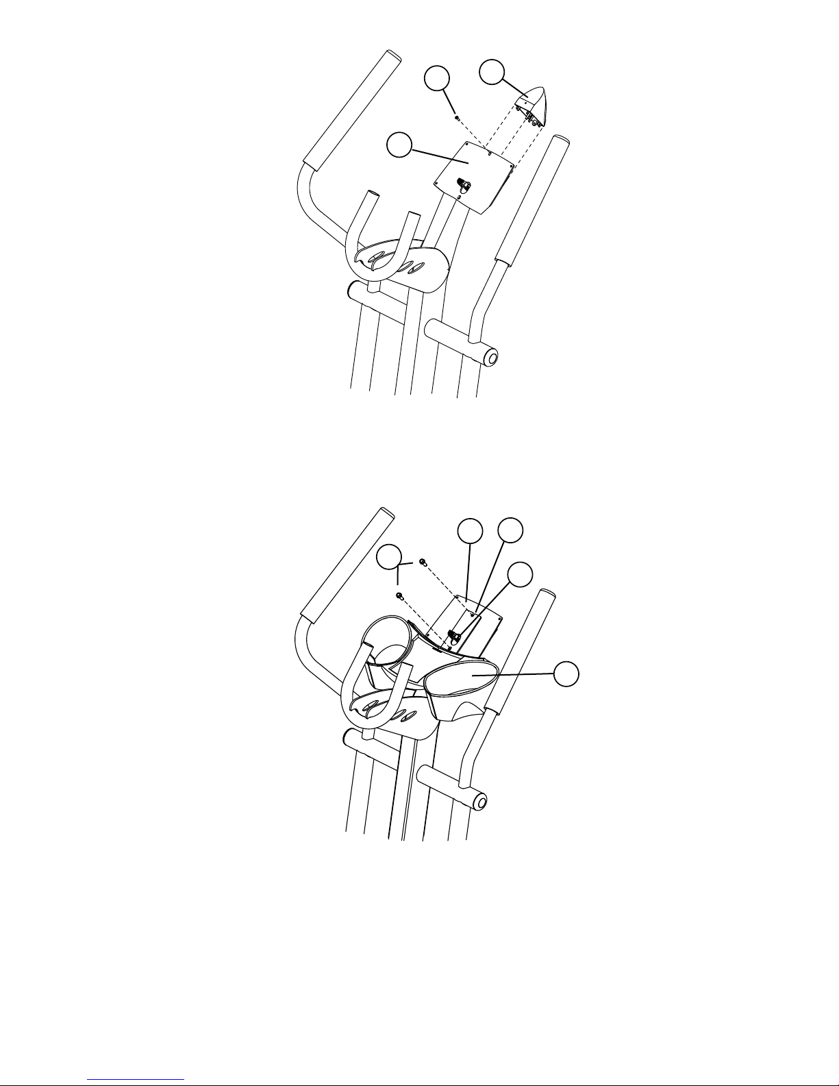
STEP 5
Attach Plastic Upright Cap to upright assembly:
1. Push the Plastic Upright Cap (E) into the open end of the tube at the top of the upright tube assembly (A).
2. Line up the hole in Plastic Upright Cap (E) with hole in upright tube assembly and fasten with a (#3) screw.
K
H
O
J
G
STEP 6
Attach heart rate accessory tray to upright assembly:
NOTE: This step applies to model X5i only.
1. It is helpful to form the threads in the console plate (H) before attaching the accessory tray (G). Using a #3 Phillips screwdriver,
start the (#0) self-tapping screws into the holes. When threads have formed,
2. Feed the upper wire harness (J) through the slot in the accessory tray bracket (K).
3. Line up the holes on the accessory tray bracket (K) with the holes on the console plate (H), and then secure the accessory tray
with the two (#0) self-tapping screws using a #3 Phillips screwdriver.
remove the screws.
8
1.4 SETUP (CONTINUED)
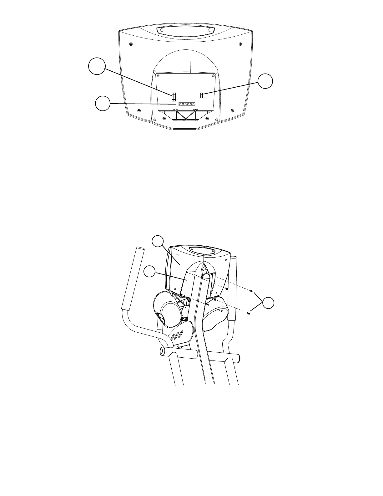
10P
3P
6P
STEP 7
Plug cables into the back of display console:
1. Plug the 10-pin connector at the end of the upper wire harness into the 10-pin connector (10P) in the back of the display console.
Make sure the connector snaps into place.
NOTE: #2 and #3 apply to model X5i only.
2. Plug the 3-pin connector at the end of the heart rate cable into the 3-pin (3P) connector in the back of the display console. Make
sure the connector snaps into place.
3. Plug in flat 6 pin (6P) connector for the Activity Zone.
4. Push excess cable(s) into the opening of the upright tube assembly (A).
L
H
2
STEP 8
Attach the display console to the console plate:
1. Line up the four holes in the back of the console plate (H) with the four holes in the back of the display console (L).
2. Attach the display console (L) using the four (#2) screws. Be careful not to pinch cables between the console and the console
plate. Be sure to get each screw started before fully tightening.
NOTE: To avoid stripping, do not over tighten screws.
9
 Loading...