

Life Fitness MX310 User Manual

Classic Series Upright Lifecycle®Exercise Bike
Assembly Instructions

Congratulations...
and welcome to the world of
The following Parts Identification Listing and the step-by-step assembly
procedures have been assembled to make the set-up of the Exercise Bike as
quick and easy as possible.
Please take special note of the following important points prior to choosing a
location and beginning assembly of the Exercise Bike.

IMPORTANT SAFETY INSTRUCTIONS!
DO NOT
DO NOT
in water. Contact Life Fitness Customer Support Services at the number in the Operation Manual.
DO NOT
DO NOT
center to center to avoid interference (cross talk) between Heart Rate monitors.
DO
DO
verify the contents of the delivery carton against the accompanying Parts Listing prior to setting
the cartons and shipping material aside. If any parts are missing, contact Life Fitness Customer
Support Services at the number listed in the Operation Manual. Save the shipping cartons in case of
return.
DO
read the entire Operation Manual prior to attempting to operate this machine as this is essential
for proper use.
NE PAS placer le vélo d’exercice allongé Lifecycle à l’extérieur, près d’une piscine ou dans un
endroit très humide.
NE PAS faire fonctionner le vélo d’exercice allongé Lifecycle s’il est tombé, s’il a été endommagé ou
s’il a été partiellement plongé dans l’eau. Téléphoner au service après-vente de Life Fitness dont le
numéro figure sur la couverture arrière du guide d’installation.
NE PAS placer le vélo d’exercice allongé Lifecycle à moins de 76 cm (30 po) d’un poste de
télévision.
MAINTENIR la zone autour du vélo d’exercice allongé Lifecycle libre de toute obstruction, y compris
murs et meubles.
VÉRIFIER si l’emballage contient toutes les pièces de la liste jointe avant de le mettre de côté. Si des
pièces manquent, téléphoner au service après-vente de Life Fitness dont le numéro figure sur la
couverture arrière du guide d’installation. Conserver l’emballage au cas où l’appareil devrait être
renvoyé.
LIRE le manuel de l’utilisateur tout entier avant d’essayer de faire fonctionner cet appareil. Ceci est
indispensable à son utilisation correcte.
locate the Exercise Bike outdoors, near swimming pools, or in areas of high humidity.
operate your Exercise Bike if it has been dropped, damaged, or even partially immersed
locate the Exercise Bike any closer than 30 inches (76 cm) to a television set.
locate additional Exercise Bike any closer than a minimum of 42 inches (107 cm) from
keep the area around your Exercise Bike clear of any obstructions, including walls and furniture.
T
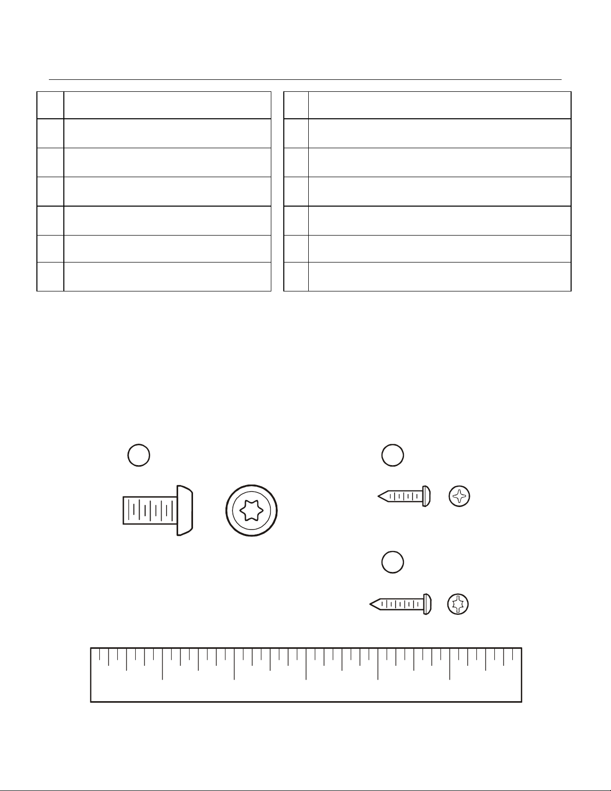
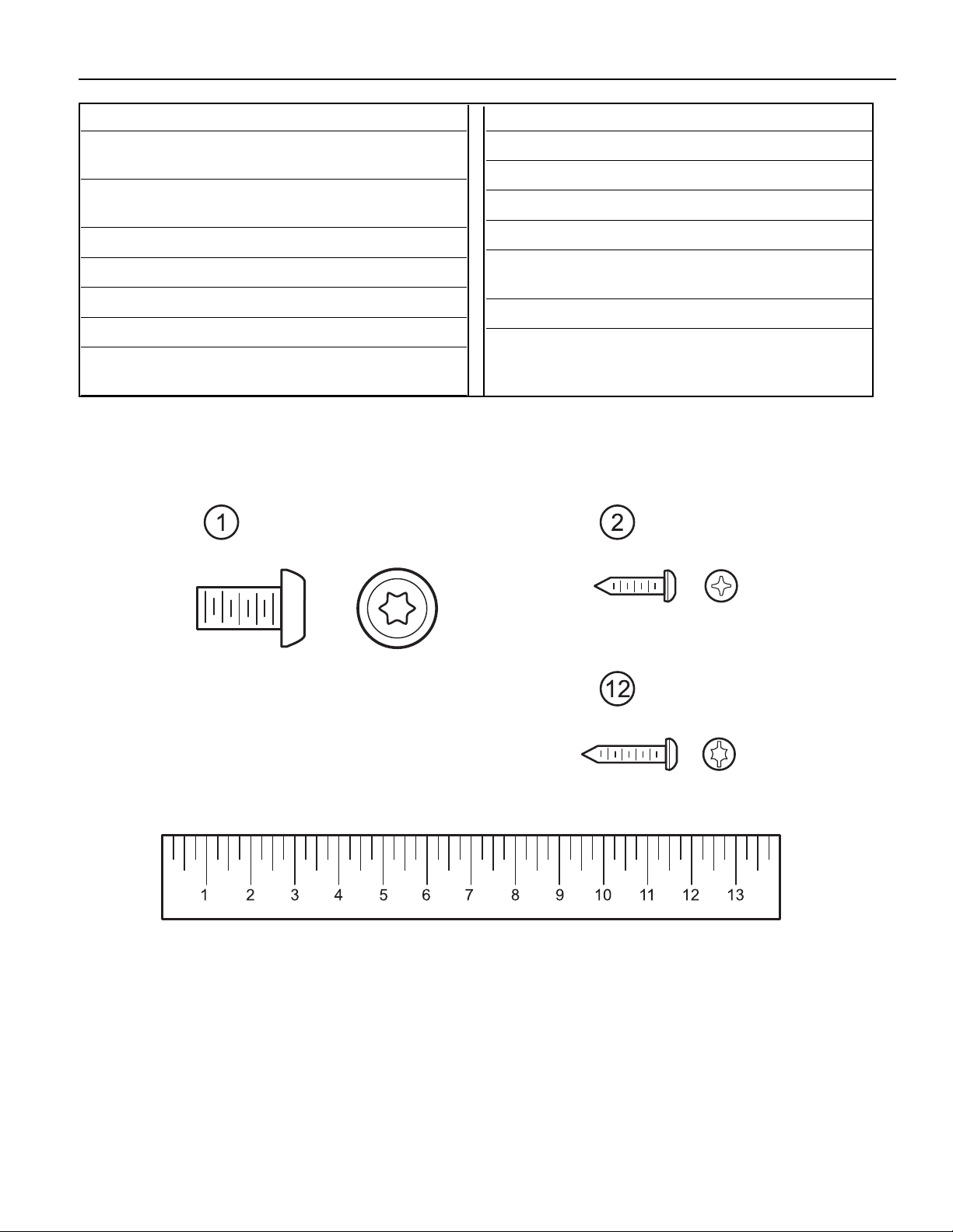
OOLS REQUIRED FOR ASSEMBLY...
P
ARTS DESCRIPTION
1 Torx Button Mounting Bolt Qty: 8
3/8-16 x 3/4”
3 Accessory Tray Qty: 1
5 Top Cover Qty: 1
7 Left Seat Post Shroud Qty: 1
9 Left Pedal Strap Qty: 1
11 Handlebar Qty: 1
13 Polar Receiver Qty: 1
Phillips screwdriver, T-45 Torx Driver, T-20 Torx Driver
2 Phillips Pan Head Screw Qty: 12
8-18 x 5/8”
4 Console Assembly Qty: 1
6 Bottom Cover Qty: 1
8 Right Seat Post Shroud Qty: 1
10 Right Pedal Strap Qty: 1
12 Torx / Standard Screw Qty: 1
#8-18 x 3/4”
14 Polar Receiver Sleeve Qty: 1
1 2
15
1” 2” 3” 4” 5”
Please read this prior to assembly.
This product is preconfigured to accept the addition of the Life Fitness Attachable TV System. A
POWER CABLE and COAXIAL CABLE have been pre-installed. Please read both the product
assembly instructions and Attachable TV System assembly instructions (included with the Life
Fitness Attachable TV System) prior to assembly.
Route the POWER CABLE and COAXIAL CABLE alongside the MAIN WIRE HARNESS where
applicable.
5
4
1
11
6
2
2
3
8
2
1
7
12
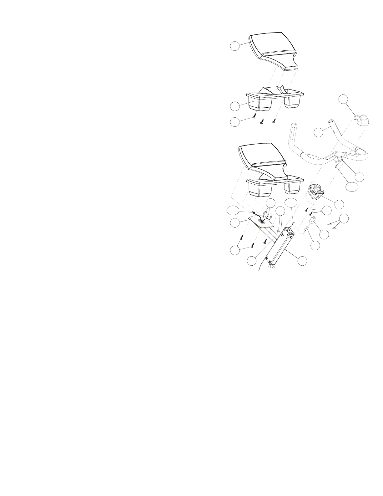
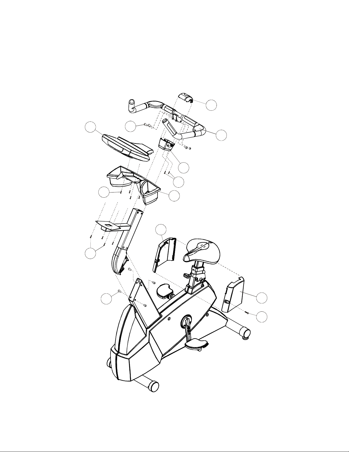
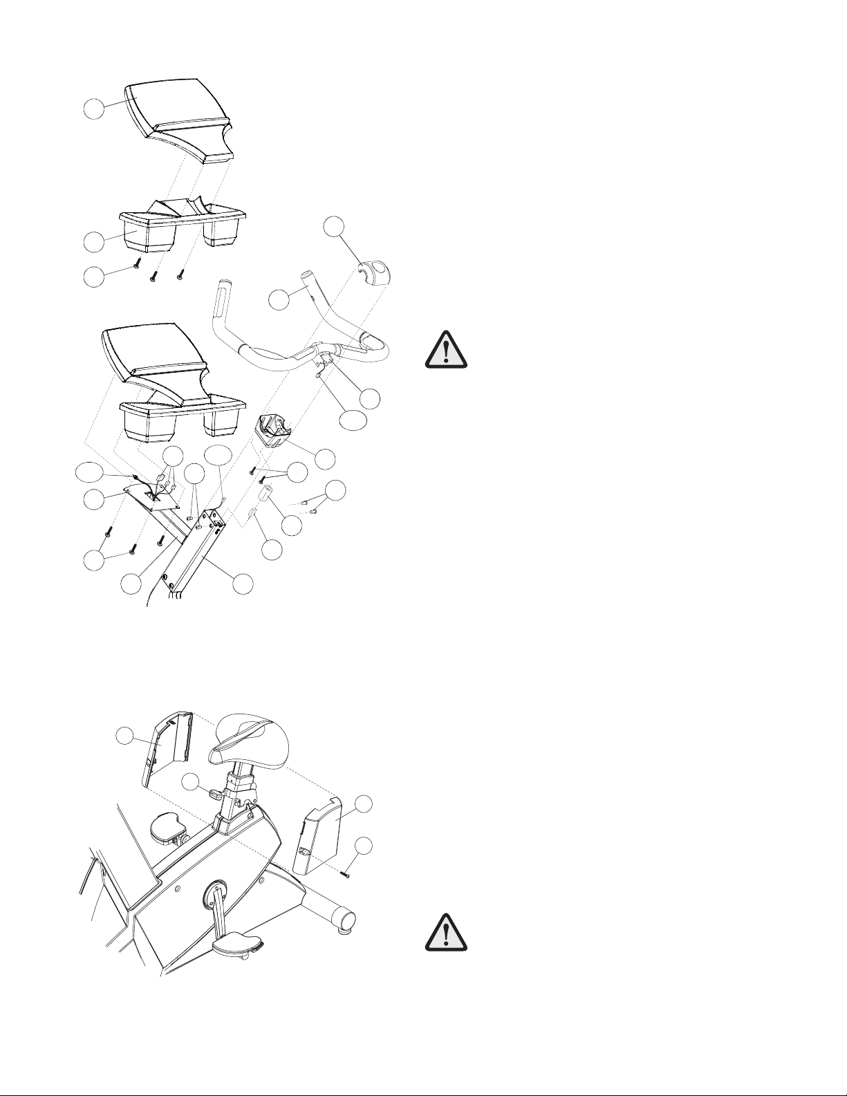
1.
Locate the BOTTOM COVER (#6). Position the cover as
shown with the notch of the center hole facing downward.
Slide the BOTTOM COVER down over the UPPER CONSOLE
SUPPORT TUBE (A) until it rests against the FRONT TUBE
EXTENSION (B).
2.
Position the HANDLEBAR (#11) as shown near the UPPER
CONSOLE SUPPORT TUBE (A).
3.
Connect the 4-PIN HEART RATE CONNECTOR (4P) leading
from the HANDLEBAR (#11) center to the 4-PIN HEART
RATE CONNECTOR (4P) leading from the UPPER
CONSOLE SUPPORT TUBE (A).
4.
Carefully slide the HANDLEBAR MOUNTING FLANGES (C)
into the UPPER CONSOLE SUPPORT TUBE (A).
NOTE: BE CAREFUL NOT TO PINCH THE HEART RATE
CABLE WHEN INSERTING THE HANDLEBAR FLANGES (C)
INTO THE UPPER CONSOLE SUPPORT TUBE (A).
5.
Secure the HANDLEBAR (#11) to the UPPER CONSOLE
SUPPORT TUBE (A) using four MOUNTING BOLTS (#1).
Tighten the SCREWS to 15-20 ft. lbs.
6.
Insert the POLAR RECEIVER (#13) into the polar receiver
receptacle located at the center of the UPPER CONSOLE
SUPPORT TUBE (A). Slide the POLAR RECEIVER SLEEVE
(#14) over the POLAR RECEIVER covering the entire POLAR
RECEIVER.
7.
Locate the TOP COVER (#5). Slide the BOTTOM COVER
(#6) upward toward the HANDLEBAR (#11) until it contacts
the HANDLEBAR. Position the TOP COVER over the POLAR
RECEIVER (#13) and HANDLEBAR and align it to the
BOTTOM COVER. Secure the TOP COVER to the BOTTOM
COVER using four PHILLIPS SCREWS (#2) as shown.
8.
Align the ACCESSORY TRAY (#3) to the bottom of the
DISPLAY CONSOLE (#4) as shown. Secure the
ACCESSORY TRAY to the DISPLAY CONSOLE using four
PHILLIPS SCREWS (#2).
9.
Position the DISPLAY CONSOLE (#4) above the MOUNTING
BRACKET (D) as shown. Attach all CONNECTORS (E)
leading from the DISPLAY CONSOLE MOUNTING BRACKET
to the corresponding CONNECTORS located on the back of
the DISPLAY CONSOLE.
10.
Attach the DISPLAY CONSOLE (#4) to the DISPLAY
CONSOLE MOUNTING BRACKET (D) using four SCREWS
(#2).
4
5
3
2
11
C
4P
4P
E
1
D
2
B
13
A
6
2CX
1
14
NOTE: BE CAREFUL NOT TO PINCH ANY CABLES WHEN
SECURING THE DISPLAY CONSOLE (#4) TO THE DISPLAY
CONSOLE MOUNTING BRACKET (D).
Tighten the screws securely.
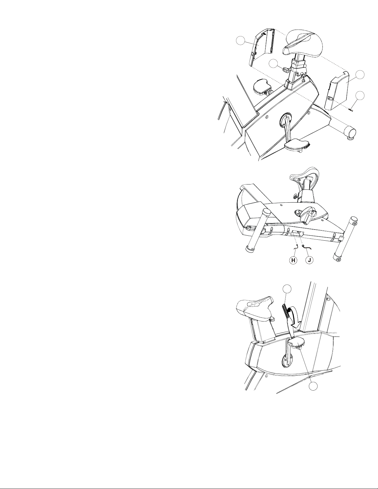
11.
Locate the USER LEFT AND RIGHT SEAT POST COVERS
(#7 & #8). Position the USER LEFT SEAT POST COVER (#7)
below the seat covering the ADJUSTMENT LEVER (F) as
shown. Interlock the two tabs of the USER RIGHT SEAT
POST COVER (#8) to the corresponding slots of the USER
LEFT SEAT POST COVER and pivot it forward to meet the
USER LEFT SEAT POST COVER enclosing the SEAT
ADJUSTMENT LEVER. Secure the SEAT POST COVERS
together using one SCREW (#12).
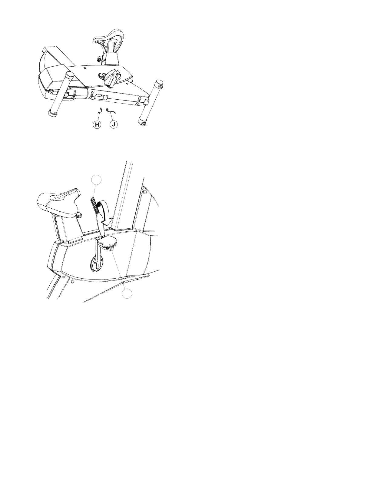
12.
Locate the RIGHT PEDAL STRAP (#10) marked with an “R”.
Attach the RIGHT PEDAL STRAP to the RIGHT PEDAL (G)
with the double slot on the inward pedal strap tab looping
upward and attaching to the outward pedal strap tab. Repeat
for the LEFT PEDAL STRAP (#9) marked with an “L”.
8
F
7
12
10
G

PHYSICAL DIMENSIONS:
Length: 48 inches / 122 centimeters
Width: 24 inches / 61 centimeters
Height: 54 inches / 137 centimeters
Weight: 107 pounds / 49 kilograms
PRE-OPERATION CHECKLIST
Ensure that the console support screws are tight.
Make sure the
Exercise Bike
is properly leveled and stable.
Ensure that the Leveler Jam Nuts are tight.
Read the entire Operation Manual before using the
Before attempting to operate your Exercise Bike, it is imperative that you familiarize yourself with the
contents of the Operation Manual. If your Exercise Bike does not respond as described in the OPERATION
MANUAL, contact the nearest Life Fitness service center as listed in the Operation Manual.
Exercise Bike
.
©2008 Life Fitness, a division of Brunswick Corporation. All rights reserved. Life Fitness is trademark of Brunswick Corporation.
Polar is a registered trademark of Polar Electro, Inc. M051-00K63-B264 05.08

Classic Series Lifecycle
®
BBiicciicclleettaass vveerrttiiccaalleess ppaarraa eejjeerrcciicciiooss
INSTRUCCIONES DE MONTAJE

2
Enhorabuena...
y bienvenido al mundo de
La siguiente lista de identificación de piezas y los procedimientos de instalación paso a paso se han organizado para facilitar y agilizar el montaje de las bicicletas para ejercicios.
Preste especial atención a los siguientes puntos importantes antes de elegir un lugar y empezar a montar
las bicicletas reclinadas para ejercicios.

3
¡INSTRUCCIONES IMPORTANTES DE SEGURIDAD!
± NO coloque la bicicleta para ejercicios al aire libre, cerca de piscinas ni en áreas de mucha humedad.
± NO use la bicicleta para ejercicios si se ha caído, dañado o incluso sumergido parcialmente en agua. Póngase
en contacto con el Servicio de Asistencia al Cliente de Life Fitness llamando al número indicado en el Manual
de Operación.
± NO coloque la bicicleta para ejercicios a una distancia menor de 30 in. (76 cm) de un televisor.
± NO coloque otras bicicletas para ejercicios a una distancia entre centros inferior a 42 in. (107 cm), para evitar
la interferencia (diafonía) entre los monitores de frecuencia cardíaca.
± MANTENGA el área alrededor de la bicicleta para ejercicios libre de obstrucciones, incluyendo paredes y
muebles.
± VERIFIQUE el contenido de la caja de entrega comparando con la lista de piezas que la acompaña, antes de
apartar las cajas y los materiales de envío. Si faltaran piezas, póngase en contacto con el Servicio de
Asistencia al Cliente de Life Fitness llamando al número indicado en el Manual de Operación. Guarde las
cajas de envío en caso de que necesite devolver la unidad.
± LEA el Manual de Operación en su totalidad antes de usar esta máquina, ya que es imprescindible para
usarla correctamente.
4
HERRAMIENTAS REQUERIDAS PARA EL MONTAJE... DESTORNILLADOR PHILLIPS, LLAVES DE TUERCAS TORX T-45 Y T-20
Descripción de las piezas
1 Perno de montaje de cabeza Torx Cant: 8
3/8-16 x 3/4"
2 Tornillo Phillips de cabeza troncocónica Cant: 12
8-18 x 5/8"
3 Bandeja para accesorios Cant: 1
4 Conjunto de consola Cant: 1
5 Cubierta superior Cant: 1
6 Cubierta inferior Cant: 1
7 Protector izquierdo de columna del asiento Cant: 1
Descripción de las piezas
8 Protector derecho de columna del asientoCant: 1
9 Correa del pedal izquierdo Cant: 1
10 Correa del pedal derecho Cant: 1
11 Manillar Cant: 1
12 Tornillo estándar / Torx Cant: 1
nº 8-18 x 3/4"
13 Receptor Polar Cant: 1
14 Funda del receptor Polar Cant: 1

5
Lea esta información antes de proceder al montaje.
Este producto ha sido preconfigurado para que acepte la adición del sistema de televisión montable Life Fitness.. Se han instalado de antemano un CABLE DE SUMINISTRO y un CABLE COAXIAL. Antes de proceder al montaje, lea las instrucciones de montaje de este producto y
las instrucciones de montaje del sistema de televisión montable (que se incluyen con el Sistema de televisión montable Life Fitness).
Tienda el CABLE DE SUMINISTRO y el CABLE COAXIAL junto al HAZ DE CABLES PRINCIPAL, donde corresponda.
6
1. Encuentre la CUBIERTA INFERIOR (n° 6). Sitúe la cubier-
ta, tal como se muestra, con la muesca del agujero central
hacia abajo. Deslice la CUBIERTA INFERIOR hacia abajo
sobre el TUBO SUPERIOR DE SOPORTE DE LA CONSOLA
(A) hasta que quede apoyado en la EXTENSIÓN DEL TUBO
DELANTERO (B).
2. Sitúe el MANILLAR (nº 11), tal como se muestra, cerca
del TUBO SUPERIOR DE SOPORTE DE LA CONSOLA (A).
3. Conecte el CONECTOR DE CUATRO CLAVIJAS DE
FRECUENCIA CARDÍACA (4P) que sale del centro del
MANILLAR (nº 11) con el CONECTOR DE CUATRO CLAVIJAS DE FRECUENCIA CARDÍACA (4P) que sale del TUBO
SUPERIOR DE SOPORTE DE LA CONSOLA (A).
4. Deslice con cuidado las PESTAÑAS DE MONTAJE DEL
MANILLAR (C) dentro del TUBO SUPERIOR DE SOPORTE
DE LA CONSOLA (A).
NOT A: TENGA CUIDADO DE NO PRENSAR EL
CABLE DE FRECUENCIA CARDÍACA AL INTRODUCIR LAS PESTAÑAS DEL MANILLAR (C) EN EL
TUBO SUPERIOR DE SOPORTE DE LA CONSOLA
(A).
5. Asegure el MANILLAR (nº 11) al TUBO SUPERIOR DE
SOPORTE DE LA CONSOLA (A) usando cuatro PERNOS DE
MONTAJE (nº 1). Apriete los TORNILLOS a 15-20 ft. lb.
(20-27 N m).
6. Introduzca el RECEPTOR POLAR (nº 13) en su recep-
táculo, que se encuentra en el centro del TUBO SUPERIOR
DE SOPORTE DE LA CONSOLA (A). Deslice la FUNDA DEL
RECEPTOR POLAR (nº 14) sobre el RECEPTOR POLAR
cubriéndolo totalmente.
7. Encuentre la CUBIERTA SUPERIOR (nº 5). Deslice
la CUBIERTA INFERIOR (nº 6) de forma ascendente hacia
el MANILLAR (nº 11), hasta que se unan. Sitúe la CUBIERTA
SUPERIOR sobre el RECEPTOR POLAR (nº 13) y el
MANILLAR y alinéela con la CUBIERTA INFERIOR. Asegure
la CUBIERTA SUPERIOR a la CUBIERTA INFERIOR usando
cuatro TORNILLOS PHILLIPS (nº 2), tal como se muestra.
8. Alinee la BANDEJA PARAACCESORIOS (nº 3) con la
parte inferior de la CONSOLA DE INFORMACIÓN (nº 4), tal
como se muestra. Asegure la BANDEJAPARAACCESORIOS
a la CONSOLA DE INFORMACIÓN usando cuatro TORNILLOS PHILLIPS (nº 2).
9. Sitúe la CONSOLA DE INFORMACIÓN (nº 4) encima del
SOPORTE DE MONTAJE (D), tal como se muestra. Conecte
todos los CONECTORES (E) que salen del SOPORTE DE
MONTAJE DE LA CONSOLA DE INFORMACIÓN en los
CONECTORES correspondientes situados en la parte
posterior de la CONSOLA DE INFORMACIÓN.
10. Fije la CONSOLA DE INFORMACIÓN (nº 4) al SOPORTE
DE MONTAJE DE LA CONSOLA DE INFORMACIÓN (D)
usando cuatro TORNILLOS (nº 2).
NOT A: TENGA CUIDADO DE NO PRENSAR NINGÚN
CABLE AL ASEGURAR LA CONSOLA
DE INFORMACIÓN (nº 4) A SU SOPORTE DE
MONTAJE (D).
Ajuste bien los tornillos.
2
3
4
2
14
6
C
5
13
A
4P
4P
D
E
11
B
1
1
2CX
8
F
7
15
7
11. Encuentre las CUBIERTAS IZQUIERDAY DERECHA DE
LA COLUMNA DELASIENTO (nº 7 y 8). Coloque la CUBIERTA IZQUIERDA DE LA COLUMNA DELASIENTO (nº 7) debajo
del asiento, cubriendo la PALANCA DE AJUSTE (F), tal como
se muestra. Entrelace las dos pestañas de la CUBIERTA
DERECHA DE LA COLUMNA DELASIENTO (nº 8) en las
ranuras correspondientes de la CUBIERTA IZQUIERDA y
gírela hacia delante para que encuentre la CUBIERTA
IZQUIERDA DE LA COLUMNA DELASIENTO, encerrando la
PALANCA DE AJUSTE DELASIENTO. Asegure las CUBIERTAS DE LA COLUMNA DELASIENTO uniéndolas con un
TORNILLO (nº 15).
12. Encuentre la CORREA DEL PEDAL DERECHO (nº 10),
marcada con una “R”. Conecte la CORREA DEL PEDAL
DERECHO al PEDAL DERECHO (G); la ranura doble en la
pestaña de correa del lado interior del pedal debe hacer un
bucle hacia arriba y conectarse a la pestaña de correa del lado
exterior del pedal. Repita esta secuencia para la CORREA
DEL PEDAL IZQUIERDO (nº 9), marcada con una “L”.
10
G
 Loading...