

LifeFitness CSHAA Assembly Instructions Manual
CLUB SERIES HIP AB/ADDUCTOR
ASSEMBLY INSTRUCTIONS
Part # 7184601
Rev E
Revision: 1/2/031

KEY PART # DESCRIPTION QTY KEY PART # DESCRIPTION
1 71710xx TOWER 1 22 3102915 3/8 X 3-1/4” BOLT 2
1A 6692601 END CAP 3 X 2 3 23 3202406 3/8 X 1-1/4” BUTTON HEAD BOLT 8
1B 3222801 PULLEY, 4.5 OD X .25 ID X 1 3 24 3233502 1/2 X 3-1/4” SHOULDER BOLT 1
1C 6866701 WASHER, RH 3/8 ID 3 25 3102807 3/8” LOW HEIGHT LOCK NUT 31
1D 3102514 WASHER, FLAT 3/8 SAE ST ZN 4 26 3221501 3/8” ACORN NUT 1
1E 3102933 3/8-16X2 UNS HEX FHB G2 ZN 2 27 3102514 3/8” SAE WASHER 38
1F 6866602 CAP, RH20 WHT (03 PLATINUM) 3 28 6866701 3/8” RH WASHER 60
1G 3102903 3/8-16X2.5 UNS HEX FHB G2 ZN 2 29 3114502 3/8” LOCK WASHER 1
1H 6480301 SPACER, FLNG 3/8 ID X 5/8 OD X 9/16 4 30 6122701 3/8 X 1” SPACER 2
1I 3102807 NYLOCK NUT, 3/8-16 LOW HT 4 31 6122704 3/8 X 1/4” SPACER 4
1J 6714901 GUIDE ROD BUSHING 1 ID X 2 2 32 3203002 SINGLE SPLIT SHAFT COLLAR 4
1K 3116201 PULLEY, 3.5 OD X 3/8 ID X 1 1 33 3203501 PILLOW BLOCK 3
1L 7184902 CABLE, BC-TP1,T2,123 1 34 6913801 WEIGHT STACK SELECTOR PIN 1
1M 6793001 PRODUCT WARNING LABEL 1 35 3108001 WEIGHT STACK CUSHION 2
2 71729xx PIVOT ARM SUPPORT 1 36 3222001 1” SHAFT COLLAR 2
3 71745xx CROSS BRACE 1 37 6020601 1/2” FLANGE SPACER 2
4 71733xx PTD ASSY, RIGHT PIVOT ARM 1 38 6714901 GUIDE ROD BUSHING 2
4A 71748xx PTD ASSY, ADJUSTMENT ARM 1 39 7184701 PLACARD LABEL, ENGLISH 1
4B 71753xx PTD ASSY, FRONT PULLEY ARM 1 40 7184801 LANGUAGE PLACARD LABEL* 1
4C 71756xx PTD ASSY, REAR PULLEY ARM 1 41 6926601 GUIDE ROD 2
4D 3104903 BRNG, FLANGE 1-1/4 OD 1 ID 2 42 6887202 10 LB. WEIGHT PLATE (STD) 20
5 71741xx LEFT PIVOT ARM 1 43 6888402 15 LB. WEIGHT PLATE (OPT) 10
6 71723xx CROSS SUPPORT 1 44 68775xx SEAT PAD 2
7 71715xx SEAT FRAME 1 45 69132xx LEG PAD 2
8 71762xx KNEE SUPPORT 2 46 6971601 WEIGHT STACK LABEL 1
9 68839xx GUIDE ROD SUPPORT 1 47 3230701 STARLOCK WASHER 8
10 3222801 4-1/2” PULLEY 2 48 6866602 RH CAP WHT 56
11 6140701 1 X 1” GLIDE 5 OR 6866603 PLATINUM RH CAP 56
12 71759xx PIVOT LINK 1 49 7177301 3/8” THREADED ROD 2
13 71765xx HANDLE 1 50 3233201 ROD END BEARING 4
14 7177001 FOOT SUPPORT 2 51 7177402 SHROUD 1
15 6925501 HEAD PLATE 1 52 3102935 3/8 X 4-1/2” BOLT 1
16 3102901 3/8 X 1-1/4” BOLT 6 53 6757701 CABLE CLIP 2
17 3102941 3/8 X 1-1/2” BOLT 2 54 6866601 BLACK RH CAP 4
18 3102933 3/8 X 2” BOLT 1 55 3102924 3/8 X 1-3/4” BOLT 1
19 31029xx 3/8 X 2-1/4” BOLT 4 56 3102903 3/8 X 2-1/2” BOLT 6
20 3102922 3/8 X 2-3/4” BOLT 11 57 3102416 CAP, END 2 X 1 6
21 3102904 3/8 X 3” BOLT 2 58 6405201 CAP, END 2 SQUARE 10
QT
Y
For all 5 digit part numbers you need to add the color at the end *LANGUAGE PLACARDS-
For weldments use the following codes These come with the product and are a sheet with all of the
07 Denotes Platinum following lanuages: Japeneese, Italian, Spanish,
08
Denotes White Dutch, French, German, and Portuguese.
For Upholstery use the following codes
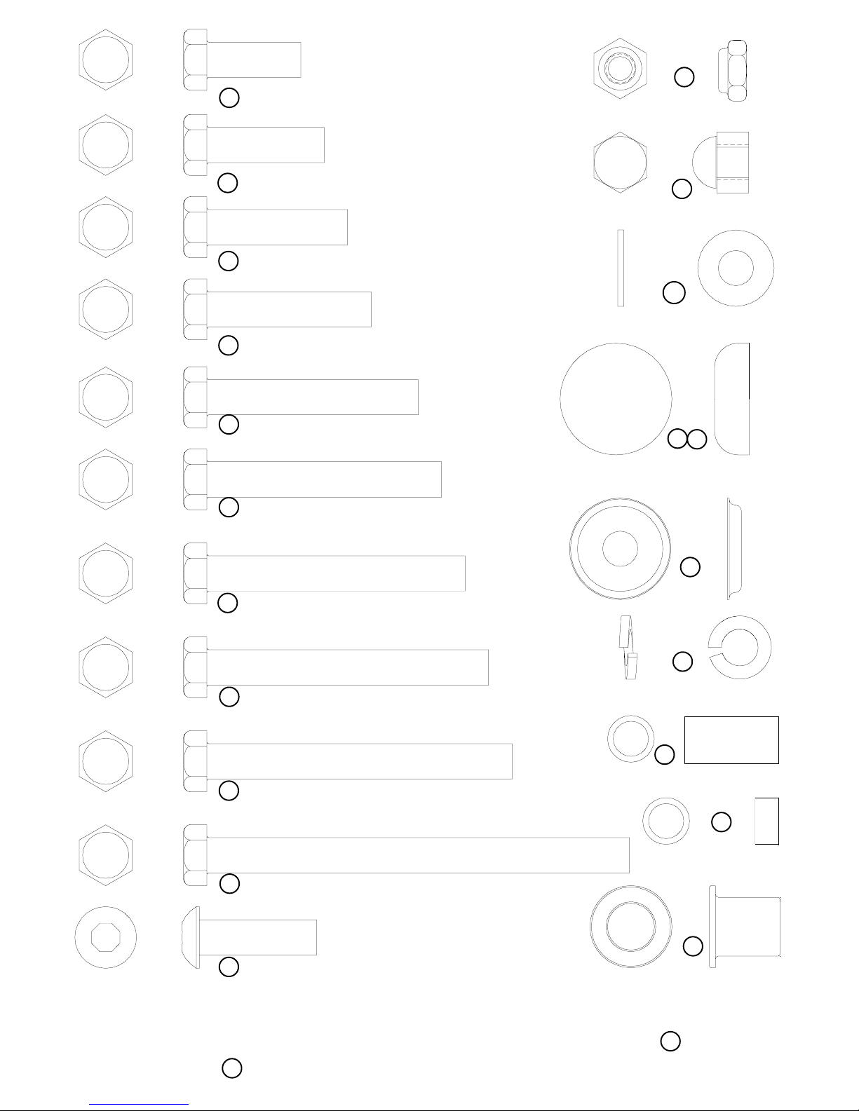
18 3/8 X 1” BOLT
25
3/8” LOW
HEIGHT LOCK
NUT
16 3/8 X 1-1/4” BOLT
17 3/8 X 1-1/2” BOLT
55 3/8 X 1-3/4” BOLT
19 3/8 X 2-1/4” BOLT
56 3/8 X 2-1/2” BOL T
20 3/8 X 2-3/4” BOLT
26
3/8”ACORN NUT
27
3/8” SAE
WASHER
48
54
RH CAP
(WHITE/PLATINUM/BLACK)
28
RH
WASHER
21 3/8 X 3” BOLT
22 3/8 X 3-1/4” BOLT
52 3/8 X 4-1/2” BOLT
23 3/8 X 1-1/4” BUTTON HEAD BOLT
24 1/2 X 3-1/4” SHOULDER BOLT
29
3/8”
LOCK W ASHER
30
3/8 X 1”
SP ACER
31
3/8 X 1/4”
SP ACER
37
1/2”
FLANGE BEARING
47
STARLOCK
3
WASHER
1
25
48
6
28
27
20 3/8 X 2-3/4”
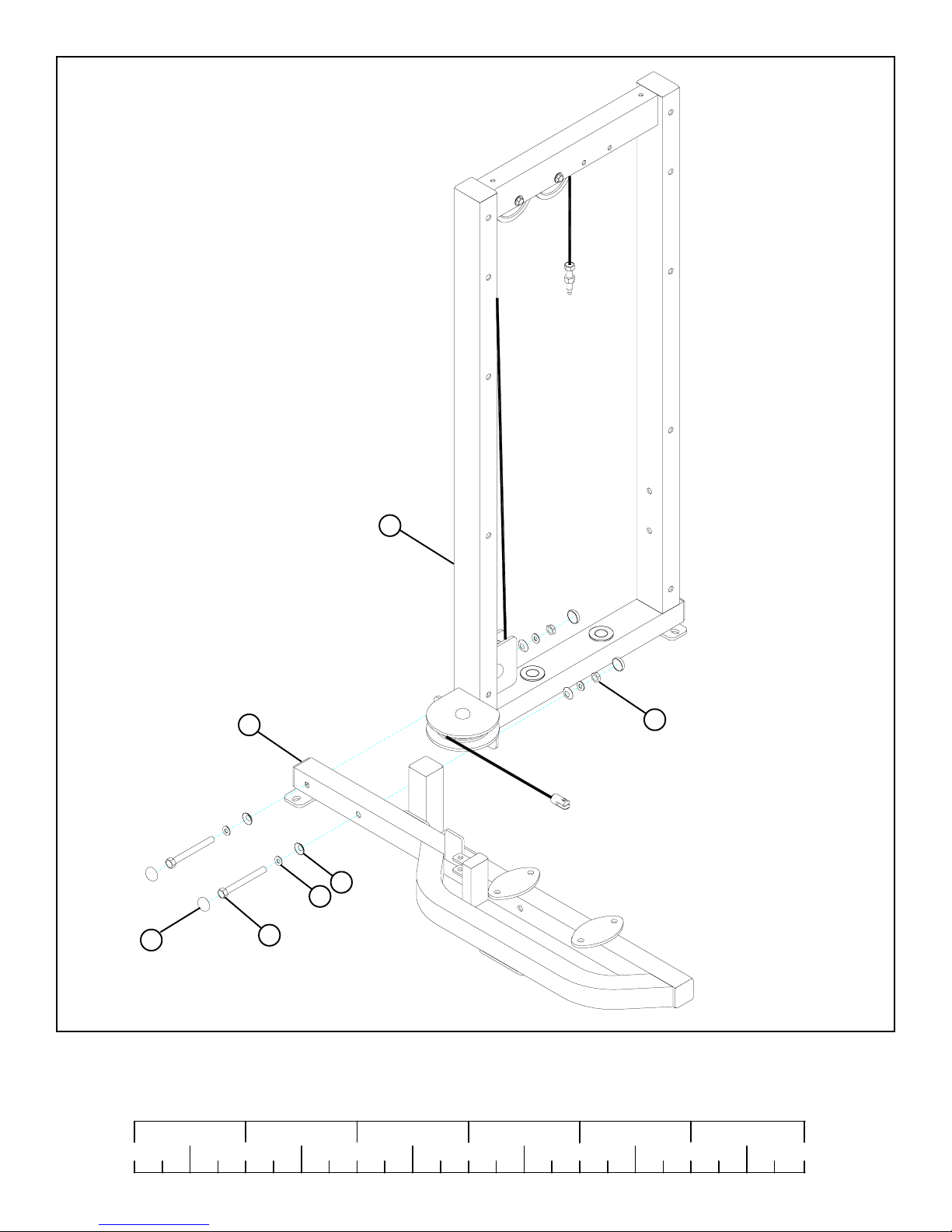
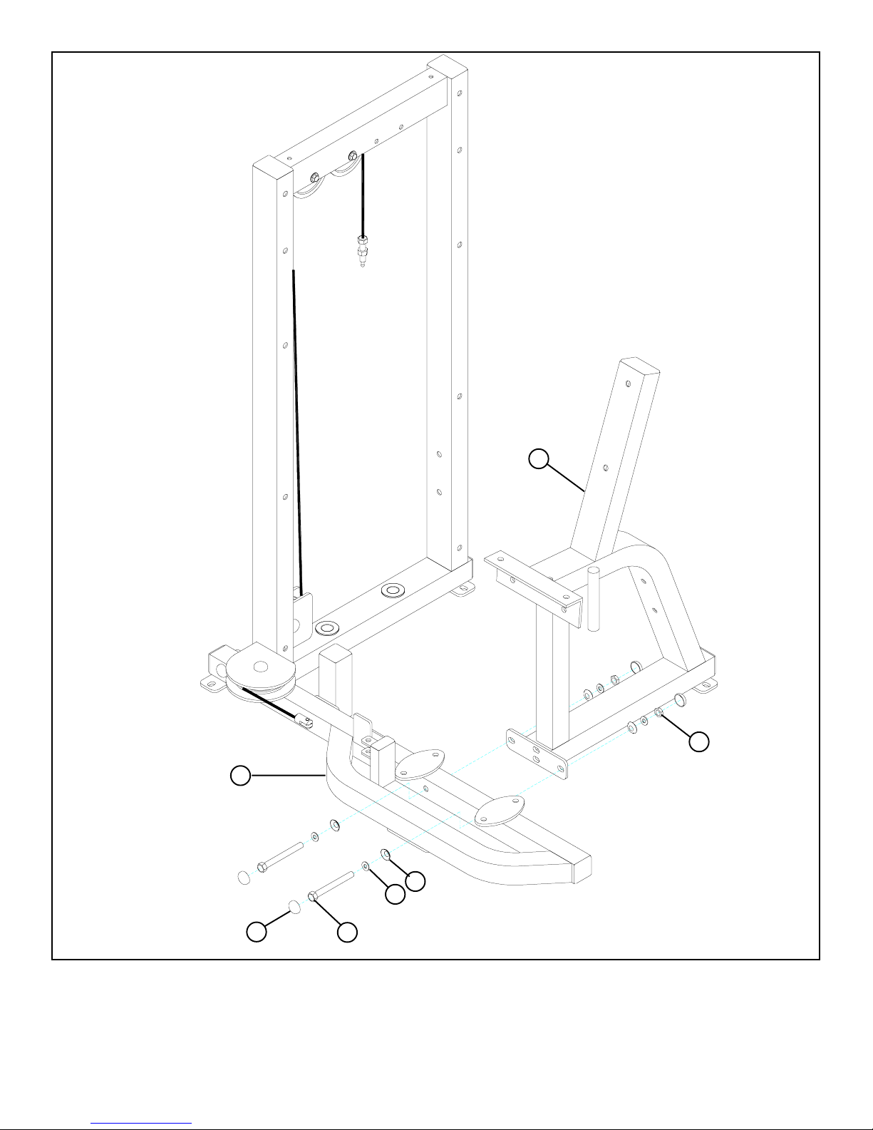
FIGURE 1
STEP 1:
• LOOSELY assemble the CROSS SUPPORT (6) to the TOWER (1) using four RH CAPS (48), two 3/8 X 2-3/4” BOLTS (20), four
3/8” SAE WASHERS (27), four 3/8” RH WASHERS (28) and two 3/8” LOW HEIGHT LOCK NUTS (25) as shown in FIGURE 1.
1/2 1/2 1/2 1/2 1/2 1/2
0
1
2
345
6
4
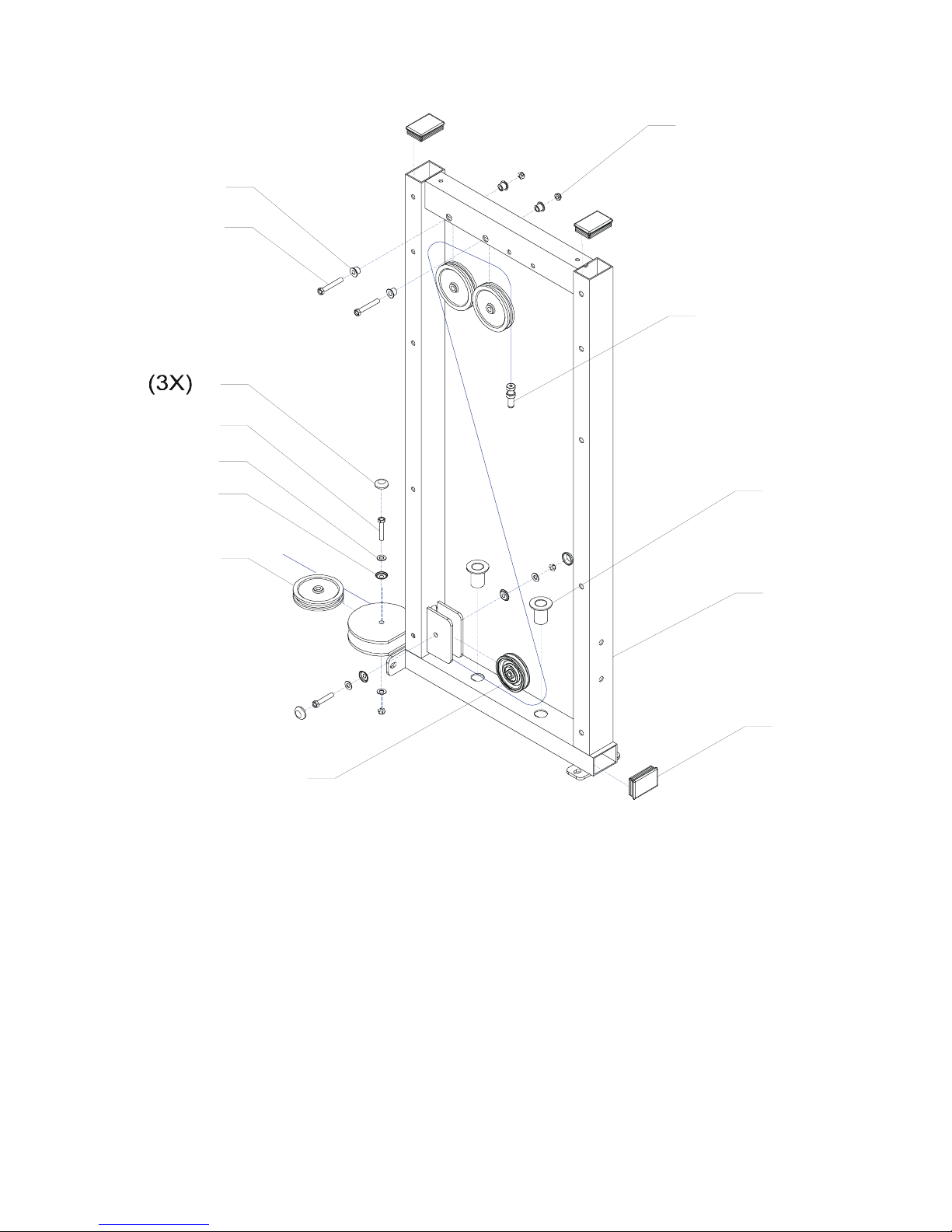
1I
(4X)
(4X)
(2X)
(2X)
(4X)
(3X)
(3X)
1H
1G
1F
1E
1D
1C
1B
1L
1J
1
(2X)
1K
1A (3X)
6
7
25
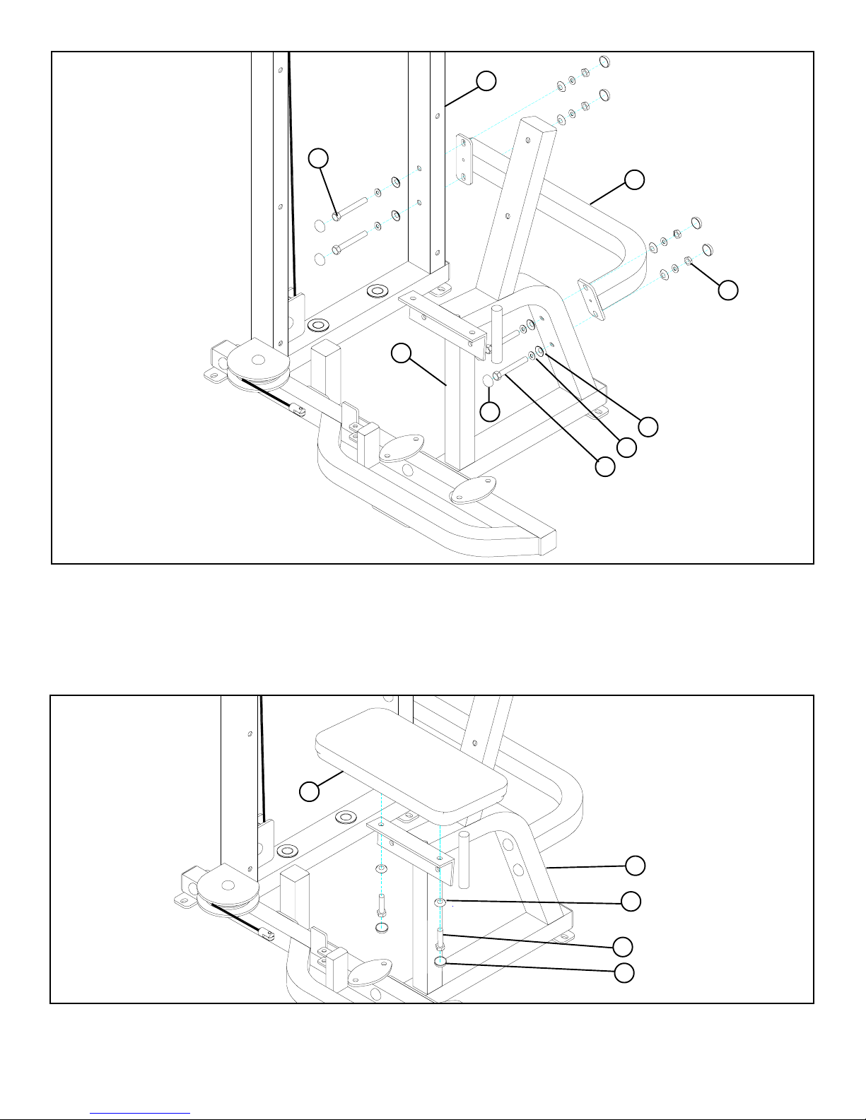
FIGURE 2
48
STEP 2:
• LOOSELY assemble the SEAT FRAME (7) to the CROSS SUPPORT (6) using four RH CAPS (48), two 3/8 X 2-3/4” BOLTS (20),
four 3/8” SAE WASHERS (27), four 3/8” RH WASHERS (28) and two 3/8” LOW HEIGHT LOCK NUTS (25) as shown in
FIGURE 2.
28
27
20 3/8 X 2-3/4”
5
20 3/8 X 2-3/4”
1
3
25
7
48
28
27
20 3/8 X 2-3/4”
FIGURE 3
STEP 3:
• LOOSELY assemble the CROSS BRACE (3) to the SEAT FRAME (7) and the TOWER (1) using eight RH CAPS (48), four 3/8 X
2-3/4” BOLTS (20), eight 3/8” SAE WASHERS (27), eight 3/8” RH WASHERS (28) and four 3/8” LOW HEIGHT LOCK NUTS
(25) as shown in FIGURE 3.
• Securely tighten all loose frame connections made to this point, then proceed to snap RH
CAPS (48) over the RH WASHERS (28) on all tightened connections.
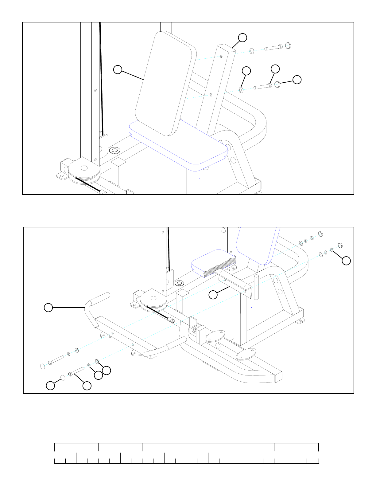
FIGURE 4
44
7
28
18 3/8 X 1”
STEP 4:
• SECURELY assemble the SEAT PAD (44) to the SEAT FRAME (7) using two RH CAPS (48), two 3/8 X 1” BOLTS (18) and two
3/8” RH WASHERS (28) as shown in FIGURE 4.
48
6
7
44
28
21 3/8 X 3”
48
FIGURE 5
STEP 5:
• SECURELY assemble the SEAT PAD (44) to the SEAT FRAME (7) using two RH CAPS (48), two 3/8 X 3” BOLTS (21) and two
3/8” RH WASHERS (28) as shown in FIGURE 5.
FIGURE 6
7
2
28
27
48
20 3/8 X 2-3/4”
STEP 6:
• SECURELY assemble the PIVOT ARM SUPPORT (2) to the SEAT FRAME (7) using four RH CAPS (48), two 3/8 X 2-3/4”
BOLTS (20), four 3/8” SAE WASHERS (27), four 3/8” RH WASHERS (28) and two 3/8” LOW HEIGHT LOCK NUTS (25) as
shown in FIGURE 6.
25
1/2 1/2 1/2 1/2 1/2 1/2
0
1
2
345
7
6
4
4d
33
LIGHTLY
TIGHTEN!
4a
58
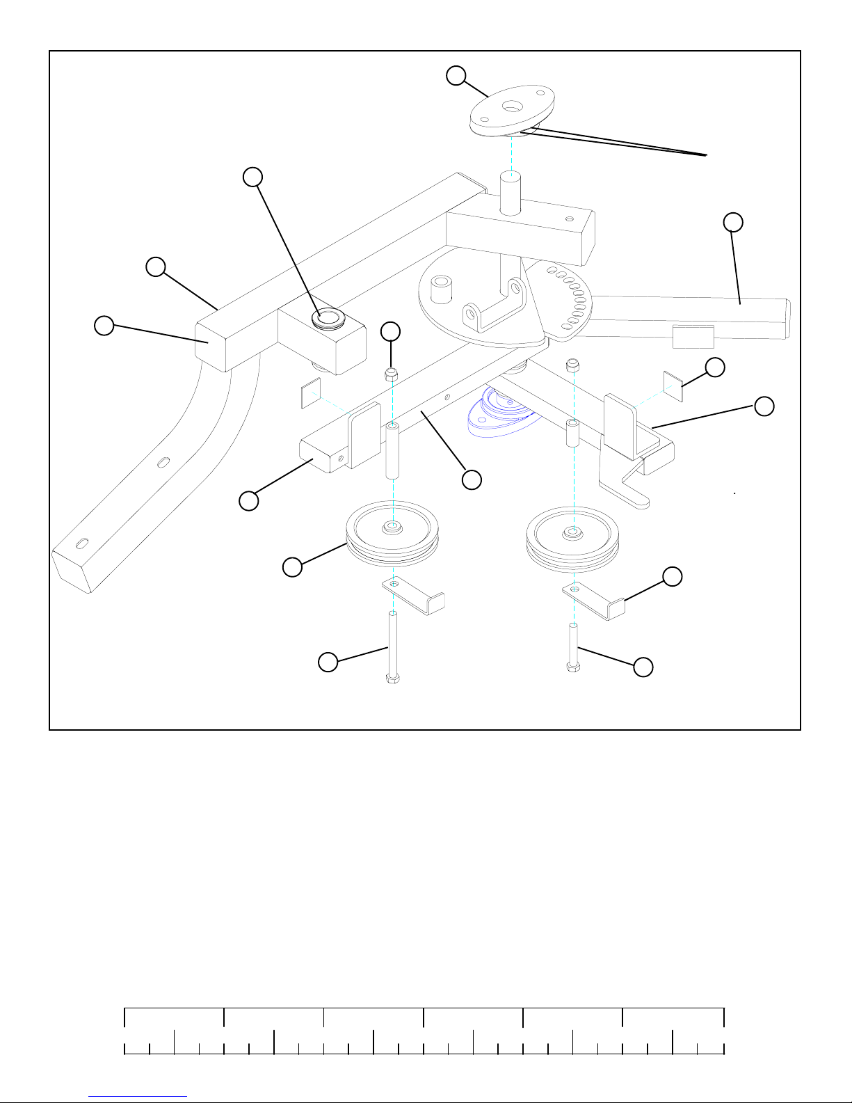
FIGURE 7
57
10
3/8 X 4-1/2” 52
25
11
4c
4b
53
20 3/8 X 2-3/4”
STEP 7:
• Slide one PILLOW BLOCK (33) over the shaft on the RIGHT PIVOT ARM (4.
• LOOSELY assemble one 4-1/2” PULLEY (10) to the middle rectangular tube on the RIGHT PIVOT ARM (4) using one 3/8 X 2-
3/4” BOLT (20), one CABLE CLIP (53) and one 3/8” LOW HEIGHT LOCK NUT (25) as shown in FIGURE 7.
• LOOSELY assemble one 4-1/2” PULLEY (10) to the bottom rectangular tube on the RIGHT PIVOT ARM (4) using one 3/8 X 4-
1/2” BOLT (52), one CABLE CLIP (53) and one 3/8” LOW HEIGHT LOCK NUT (25) as shown in FIGURE 7.
• Assemble two 1 X 1” GLIDES (11) to the top of the L-brackets on the RIGHT PIVOT ARM (4) as shown in FIGURE 7.
1/2 1/2 1/2 1/2 1/2 1/2
0
1
2
345
8
6
 Loading...