

CLUB SERIES VERTICAL
KNEE RAISE
Part # 7335201
Rev. C
ASSEMBLY INSTRUCTIONS
Revision:11/15/021
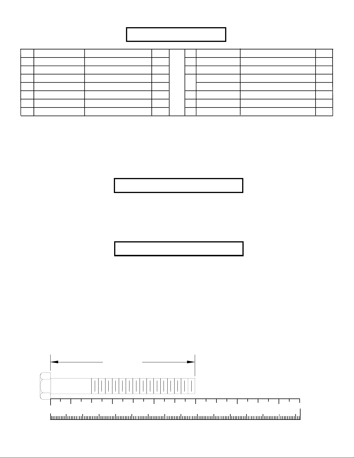
PARTS LIST
You must add ACU to each part number to connote that the part is an
Acufit produced part. Example; ACUP04-0006 This is the Cross support
weldment.
KEY
1
2
3
4
5
6
7
P04-0004-L
P04-0004-R
DA1C03807716NU
DA1C03809316NU
DC120010510U
PART #
P04-0005
P04-0006
DESCRIPTION
LEFT FRAME
RIGHT FRAME
BACK SUPPOR T
CROSS SUPPORT
3/8 X 77mm BOL T
3/8 X 93 mm BOL T
3/8” SAE W ASHER
T ools Required for Assembly
* 9/16” wrench
* Ratchet with 9/16” socket
QTY
1
1
1
1
6
8
22
KEY
8
9
10
OR
11
12
PART #
P05-0009
DB2E03807200NU
P06-0021
P06-0021
P07-0002
P07-0003
DESCRIPTION
3/8” RH WASHER
3/8” LOW HEIGHT LOCK NUT
WHITE RH CAP
PLA TINUM RH CAP
BACK P AD
ARM P AD
QTY
22
8
22
22
1
2
Bolt Length Ruler
NOTE: BOL T LENGTH IS MEASURED FROM THE UNDERSIDE OF THE HEAD OF THE BOLT .
BOLT LENGTH
0
1/2 1/2 1/2 1/2 1/2 1/2
10 20 30 40 50 60 70 80 90 100 110 120 130 140 150
1
23456
2

5 3/8 X 77mm BOL T
9
3/8” LOW
HEIGHT LOCK
NUT
6 3/8 X 93mm BOL T
10
RH CAP
(WHITE/PLATINUM)
7
3/8” SAE
WASHER
8
3/8” RH WASHER
3

1
3
4
9
8
2
7
6 3/8 X 93mm
10
FIGURE 1
STEP 1:
• SECURELY assemble the BACK SUPPORT (3) and the CROSS SUPPORT (4) to the LEFT and RIGHT FRAME (1 & 2) using
sixteen RH CAPS (10), eight 3/8 X 93mm BOL TS (6), sixteen 3/8” SAE WASHERS (7), sixteen 3/8” RH WASHERS (8) and eight 3/8”
LOW HEIGHT LOCK NUTS (9) as shown in FIGURE 1.
4

FIGURE 2
11
12
3
5 3/8 X 77mm
7
10
8
1
2
SERIAL #
LOCATION
STEP 2:
• SECUREL Y assemble the BACK PAD (11) to the BACK SUPPOR T (3) using two RH CAPS (10), two 3/8 X 77mm BOLTS (5), two
3/8” SAE WASHERS (7) and two 3/8” RH WASHERS (8) as shown in FIGURE 2.
• SECUREL Y assemble two ARM P ADS (12) to the LEFT and RIGHT FRAMES (1 & 2) using four RH CAPS (10), four 3/8 X 77mm
BOL TS (5), four 3/8” SAE WASHERS (7) and four 3/8” RH WASHERS (8) as shown in FIGURE 2.
5

CAUTION-PLEASE READ
There is a risk assumed by individuals who use this type of equipment. To minimize risk, please
follow these rules:
1. Inspect equipment daily . Tighten all loose connections and replace worn parts immediately.
Failure to do so may result in serious injury.
2. Do not allow minors or children to play on or around this equipment.
3. Exercise with care to avoid injury .
4. Consult your physician before beginning any exercise program.
WARRANTY INFORMATION
10 YEARS STRUCTURUAL FRAME
3 YEARS PILLOW BLOCKS, PULLEYS, WEIGHT PLA TES AND GUIDE RODS
1 YEAR CABLES
90 DA YS UPHOLSTERY
PREVENTATIVE MAINTENANCE TIPS
Action DAILY WEEKLY QUARTERLY BI-ANNUALLY AS NEEDED
CLEAN
Uphol s tery
Guide Rods
Hand Grips
INSPECT
Visual Over all
Cabl e s
Hardware
Frame
Hand Grips
LUBRICATE
Guide Rods
X
X
X
X
X
X
X
X
X
Clean:
• Upholstery with mild soap and water.
• Guide rods with a cotton cloth.
• Hand grips with mild soap and water.
• Frame damage can be repaired with touch-up paint can be purchased from your LifeFitness customer service representative at
(800)351-3737.
Inspect:
• Cables for wear or damage and proper tension (should not exceed 3/4” deflection.) Pay close attention at bends and attachment
points.
• Hardware should be checked for looseness. Tighten as required.
• Frames should be inspected for wear or damage.
• Hand Grips should be checked for wear or damage
Lubricate:
• Lube the Guide Rods. Apply the lubricant to a cotton cloth, then run the cotton cloth up and down the guide rods as needed. Do not
spray lubricant directly on the Guide Rods.
Thank you for purchasing the LifeFitness CLUB SERIES VER TICAL KNEE RAISE. If unsure of proper
use of equipment, call your local LifeFitness distributor or call the LifeFitness customer service depart-
ment at (800) 351-3737.
6
 Loading...