

Page 1
CLUB SERIES TRICEP
Part # 7167101
Rev D
ASSEMBLY INSTRUCTIONS
Revision:10/12/011
Page 2

PARTS LIST
#
Y
#
Y
#02ROYAL BLUE
#03SLATE
#04CRANBERRY
#05NORTHWOODS
#06 SPACE BLUE
#07AMERICAN BEAUTY RED
#08SUEDE
#12 BLACK
#13HUNTER GREEN
#14 REGIMENTAL BLUE
#15GINGERSNAP
#16CONCORD
#17URQUOISE
#18 RASPBERRY
#19CROCUS
KEY PART
1 69928xx TOWER 1 17 3202404 3/8 X 3” BUTTON HEAD BOLT 4
1A 6988801 CABLE 1 18 3108406 3/8 X 3/4” FLAT HEAD BOLT 2
1B 6714901 GUIDE ROD BUSHING 2 19 3102807 3/8” LOW HEIGHT LOCK NUT 21
1C 6925801 LABEL, KEEP CLEAR 1 20 3221501 3/8” ACORN NUT 1
1D 6692601 3 X 2 END CAP 3 21 3102514 3/8” SAE WASHER 26
1E 3102903 3/8-16 X 2.5 BOLT 2 22 3114502 3/8” LOCK WASHER 1
1F 3102933 3/8-16 X 2 BOLT 1 23 6886701 3/8” RH WASHER 46
1G 6480301 3/8 SPACER 4 24 3233502 1/2 X 3-1/4” SHOULDER BOLT 1
1H 3102514 3/8 FLAT WASHER 2 25 6020601 1/2” FLANGE BEARING 2
1I 6866701 3/8 RH WASHER 4 26 3203501 PILLOW BLOCK 2
1J 3102807 3/8-16 NYLOCK NUT LOW HT 3 27 6913801 WEIGHT STACK SELECTOR PIN 1
1K 6866601 CAP, RH-20 BLK 4 28 3108001 WEIGHT STACK CUSHION 2
1L 3222801 4.5" PULLEY 3 29 6866601 BLACK RH CAP 6
2 69911xx ASSY, ARM SUPPORT 1 30 3222001 1” SHAFT COLLAR 2
3 69901xx ASSY, HANDLE 1 31 3116001 1-1/4” RUBBER BUMPER 3
3A 6994501 RUBBER GRIP 2 32 6714901 GUIDE ROD BUSHING 2
3B 6989801 RUBBER STOP 2 33 6912801 ACCORDION SLEEVE 2
4 69897xx ASSY, PIVOT ARM 1 34 6984101 PLACARD LABEL 1
5 68839xx GUIDE ROD SUPPORT 1 35 6986301 LANGUAGE PLACARD LABEL 1
6 6888902 CAM SHROUD 1 36 6925502 HEAD PLATE 1
7 6890902 COUNTERBALANCE 1 37 6926901 GUIDE ROD 2
8 68856xx CROSS SUPPORT 1 38 6887202 10 LB. WEIGHT PLATE (STD) 15
9 71669xx SEAT SUPPORT 1 39 6888402 15 LB. WEIGHT PLATE (OPT) 10
9A 6990602 ASSY, SEAT ADJUST BLK 1 40 69132xx ARM/CHEST PAD 4
9B 6797101 ADJ PLATE 1 41 69131xx SEAT PAD 1
9C 6897001 ADJ PLATE 15 POS 1 42 6971601 WEIGHT STACK LABEL 1
9D 3234301 SCREW 4 43 3230701 STARLOCK WASHER 4
9E 6912202 HINGE 1 44 6866602 WHITE RH CAP 40
9F 6896901 HINGE PIN 2 OR 6866603 PLATINUM RH CAP 40
9G 3102416 END CAP, 2 X 1 3 45 6861902 TOP COVER SHROUD BLK 1
9H 3221701 E-RING EXTERNAL 3/8 4 46 6862102 FRONT SIDE SHROUD BLK 2
10 68888xx 4 X 18” PLATE 1 47 6862007 FRONT PLATINUM SHROUD 1
11 3102901 3/8 X 1-1/4” BOLT 8 48 6925302 ASSY, REAR FULL SHROUD 1
12 3102924 3/8 X 1-3/4” BOLT 2 OPTION* 6921502 ASSY, FRONT FULL SHROUD 1
13 3102903 3/8 X 2-1/2” BOLT 3
14 3102922 3/8 X 2-3/4” BOLT 6
15 3102942 3/8 X 3-1/2” BOLT 2
16 3102905 3/8 X 3-3/4” BOLT 4
DESCRIPTION QT
KEY PART
DESCRIPTION QT
*For all 5 digit part numbers you need to add the color at the end.
For shrouds and weldments please use the following codes: German, Poruguese, Spanish, Japaneese, and
xxxxx07 Denotes Platinum Italian.
xxxxx08 Denotes White
*For upholstery, please use the following codes:
**Language placard kit comes with Dutch, French,
Page 3
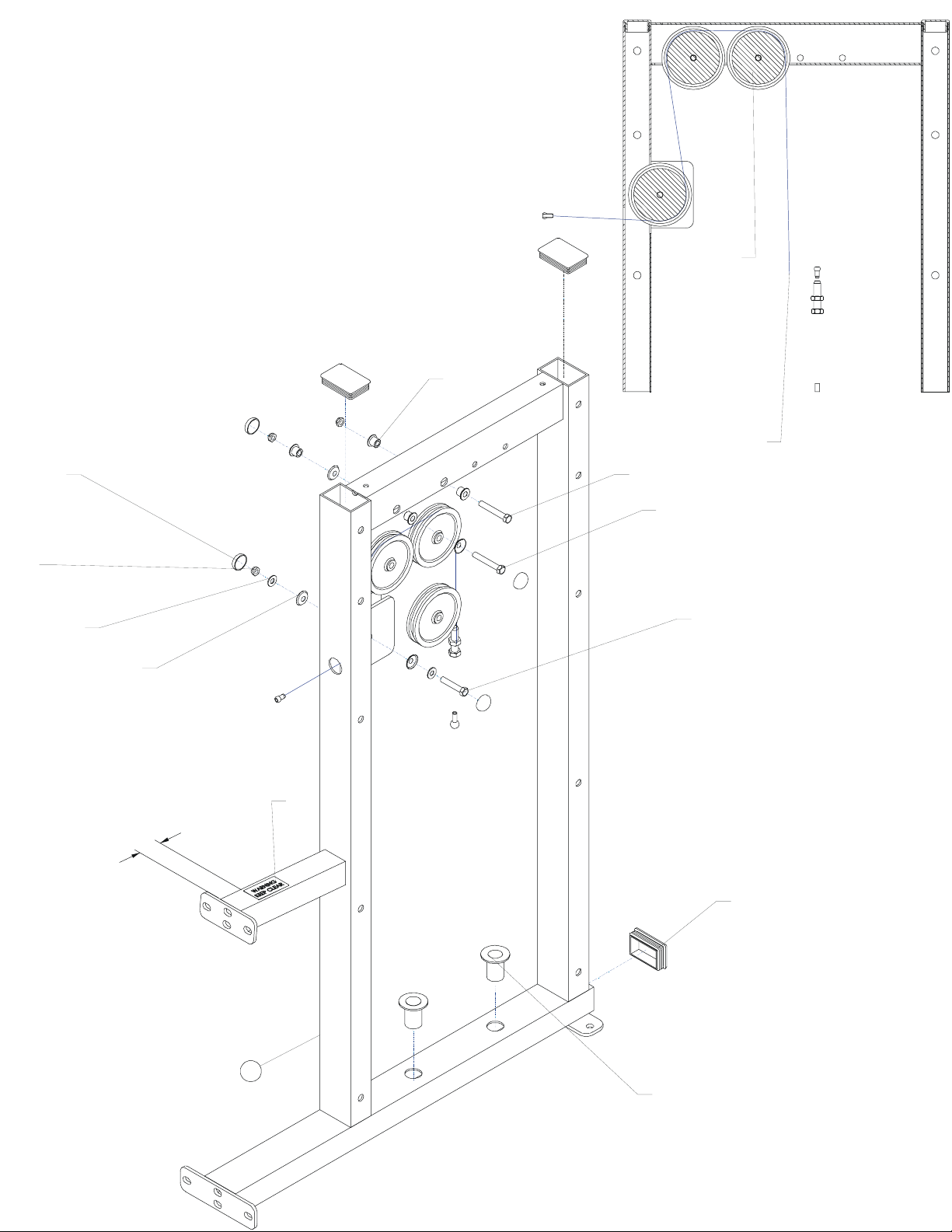
1J
1K
3X
4X
4X
1G
1E
1E
1L
3X
SECTION A-A
1A
1H
2X
1F
4X
1I
1C
2"
3X
1D
1
1B
2X
Page 4
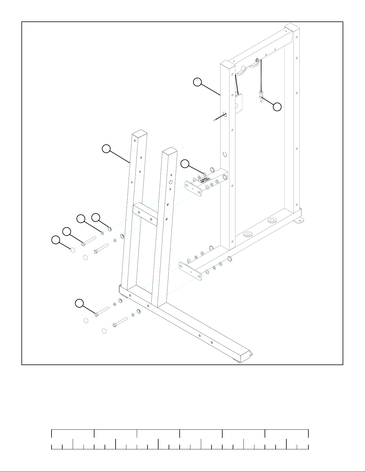
3/8 X 2-3/4” 14
44
21
1
1A
2
19
23
3/8 X 3-3/4” 16
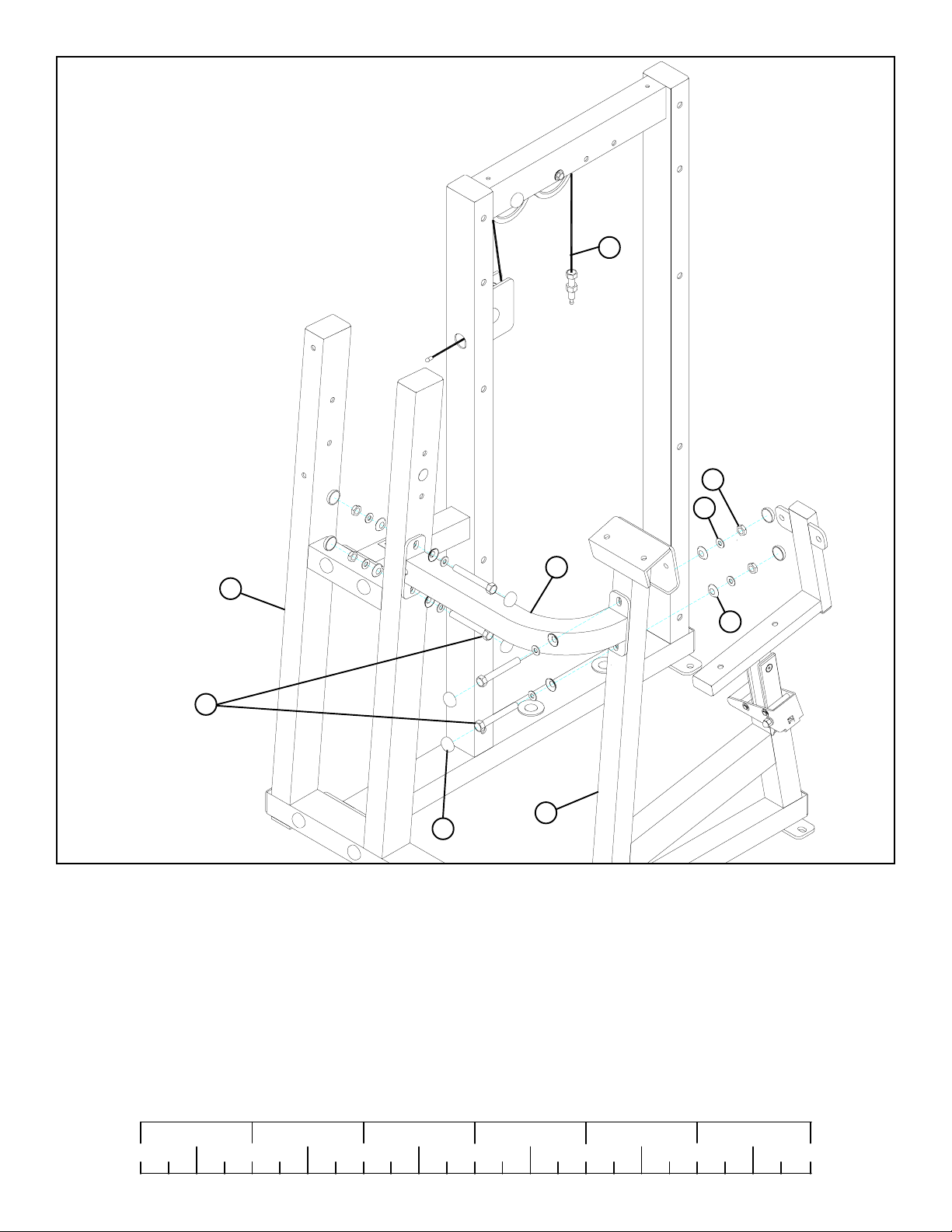
FIGURE 1
STEP 1:
• LOOSELY assemble the top of the ARM SUPPORT (2) to the TOWER (1) using four RH CAPS (44), two 3/8 X 2-3/4” BOLTS
(14), four 3/8” SAE WASHERS (21), four 3/8” RH WASHERS (23) and two 3/8” LOW HEIGHT LOCK NUTS (19) as shown in
FIGURE 1.
• LOOSELY assemble the bottom of the ARM SUPPORT (2) to the TOWER (1) using four RH CAPS (44), two 3/8 X 3-3/4” BOLTS
(16), four 3/8” SAE WASHERS (21), four 3/8” RH WASHERS (23) and two 3/8” LOW HEIGHT LOCK NUTS (19) as shown in
FIGURE 1.
1/2 1/2 1/2 1/2 1/2 1/2
0
1
2
345
4
6
Page 5
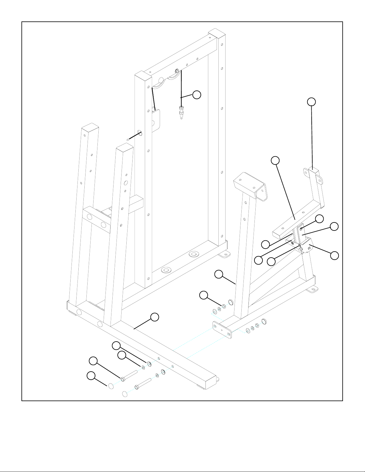
1A
9G
9A
9D
9B
9C
9E
3/8 X 3-3/4” 16
44
23
21
9F
9H
9
19
2
FIGURE 2
STEP 2:
• LOOSELY assemble the SEAT FRAME (9) to the ARM SUPPORT (2) using four RH CAPS (44), two 3/8 X 3-3/4” BOLTS (16),
four 3/8” SAE WASHERS (21), four 3/8” RH WASHERS (23), and two 3/8” LOW HEIGHT LOCK NUTS (19) as shown in
FIGURE 2.
5
Page 6
1A
19
21
8
2
23
3/8 X 2-3/4” 14
9
44
FIGURE 3
STEP 3:
• LOOSEL Y assemble the CROSS SUPPOR T (8) to the ARM SUPPORT (2) and SEAT FRAME (9) using eight RH CAPS (44), four
3/8 X 2-3/4 BOLTS (14), eight 3/8” SAE WASHERS (21), eight 3/8” RH WASHERS (23) and four 3/8” LOW HEIGHT LOCK
NUTS (19) as shown in FIGURE 3.
• Securely tighten all loose frame connections made to this point, then proceed to snap RH
CAPS (44) over the RH WASHERS (23) on all tightened connections.
1/2 1/2 1/2 1/2 1/2 1/2
0
1
2
345
6
6
Page 7

33
17 3/8 X 3”
BUTTON HEAD
26
43
4
FIGURE 4
STEP 4
• Slide two ACCORDION SLEEVES (33) and two PILLOW BLOCKS (26) over the PIVOT ARM (4) as shown in FIGURE 4
• Assemble four 3/8 X 3” BUTTON HEAD CAP SCREWS (17) and four STARLOCK WASHERS (43) to the the PILLOW
BLOCKS (26)
44
TIGHTEN!
SET SCREWS
3/8 X 3” 17
as shown in FIGURE 4.
31
2
19
21
23
4
31
FIGURE 5
STEP 5:
• SECURELY assemble the PIVOT ARM (4) to the ARM SUPPORT (2) using four previously inserted 3/8 X 3” BUTTON HEAD
CAP SCREWS (17), four RH WASHERS (23), four 3/8” SAE WASHERS (21), four 3/8” LOW HEIGHT LOCK NUTS (19) and
four RH CAPS (44) as shown in FIGURE 5.
• IMPORTANT! When PIVOT ARM (4) is centered and level in the PILLOW BLOCKS (26), tighten the PILLOW BLOCK set
screws.
• Attach two 1-1/4” RUBBER BUMPER (31) to the ARM SUPPORT (2) where the PIVOT ARM (4) shaft contacts tube in both
directions.
7
Page 8

19
7
23
21
4
13 3/8 X 2-1/2”
44
FIGURE 6
STEP 6:
• SECURELY assemble the COUNTERBALANCE (7) to the PIVOT ARM (4) using two RH CAPS (44), one 3/8 X 2-1/2” BOLT
(13), two 3/8” SAE WASHERS (21), two 3/8” RH WASHERS (23) and one 3/8” LOW HEIGHT LOCK NUT (19) as shown in
FIGURE 6.
CABLE
4
2
FIGURE 7
STEP 7:
• Rotate the PIVOT ARM (4) up to it’s resting position and slide the end of the CABLE into the bushing on the PIVOT ARM (4) as
shown in FIGURE 7.
1/2 1/2 1/2 1/2 1/2 1/2
0
1
2
345
8
6
Page 9

25
3A
3
3B
FIGURE 8
31
STEP 8:
• Insert two 1/2” FLANGE BEARINGS (25) into the HANDLE (3) as shown in FIGURE 8.
• Attach one 1-1/4” RUBBER BUMPER (31) to the HANDLE (3) as shown in FIGURE 8
FIGURE 9
4
20
22
3
24 1/2 X 3-1/4”
STEP 9:
• Assemble the HANDLE (3) to the PIVOT ARM (4) using one 1/2 X 3-1/4” SHOULDER BOLT (24), one 3/8” LOCK WASHER
(22), and one 3/8” ACORN NUT (20) as shown in FIGURE 9. (NOTE: Tighten enough to allow HANDLE to rotate freely.)
9
Page 10

3/8 X 3-1/2” 15
FIGURE 10
44
23
2
6
19
29
1A
STEP 10:
• SECURELY assemble the CAM SHROUD (6) to the ARM SUPPORT (2) using two RH CAPS (44), two BLACK RH CAPS
(29), two 3/8 X 3-1/2” BOLTS (15), four 3/8” RH WASHERS (23) and two 3/8” LOW HEIGHT LOCK NUTS (19) as shown
in FIGURE 10.
41
9A
23
9
12 3/8 X 1-3/4”
29
FIGURE 11
STEP 11:
• SECURELY assemble the SEA T PAD (41) to the seat adjust on the SEA T ADJUST (9A) using two BLACK RH CAPS (29), two 3/8 X
1-3/4” BOL TS (12) and two 3/8” RH WASHERS (23) as shown in FIGURE 10.
1/2 1/2 1/2 1/2 1/2 1/2
0
1
2
345
10
6
Page 11

40
29
11 3/8 X 1-1/4”
23
9A
FIGURE 12
STEP 12:
• SECURELY assemble the CHEST/ARM PAD (40) to the SEA T ADJUST (9A) using two RH CAPS (29), two 3/8 X 1-1/4” BOL TS (11) and
two 3/8” RH W ASHERS (23) as shown in FIGURE 12. (Note the the dir ection of the hole pattern on pad.)
40
9
23
44
FIGURE 13
11 3/8 X 1-1/4”
STEP 13:
• SECURELY assemble the CHEST/ARM P AD (40) to the SEAT FRAME (9) using two RH CAPS (44), two 3/8 X 1-1/4” BOL TS (11)
and two 3/8” RH WASHERS (23) as shown in FIGURE 13. (Note the the direction of the hole pattern on pad.)
11
Page 12

FIGURE 14
STEP 14:
3/8 X 3/4” 18
FLAT HEAD
10
23
19
44
9
• SECURELY assemble the 4 X 18” PLATE (10) to the SEAT FRAME (9) using two 3/8 X 3/4” FLAT HEAD BOLTS (18), two
3/8” RH WASHERS (23), two 3/8” LOW HEIGHT LOCK NUTS (19) and two 3/8” RH CAPS (44) as shown in FIGURE 14.
FIGURE 15
40
10
23
11 3/8 X 1-1/4”
44
STEP 15:
• SECURELY assemble two CHEST/ARM PADS (40) to the 4 X 18” PLATE (10) using four RH CAPS (44), four 3/8 X 1-1/4”
BOLTS (11) and four 3/8” RH WASHERS (23) as shown in FIGURE 15. (Note the direction of the hole pattern on the pads.)
1/2 1/2 1/2 1/2 1/2 1/2
0
1
2
345
12
6
Page 13

FIGURE 16
5
32
30
1
27
1A
36
37
38
38
39
HEAVY WEIGHT
OPTION
28
STEP 16:
• Insert the two GUIDE RODS (37) (found in SHROUD KIT box) into the base of the TOWER (1) as shown in FIGURE 16. Lubricate
the GUIDE RODS (37) with a slicon or teflon spray that is available at most hardware stores.
• Slide two WEIGHT STACK CUSHIONS (28) down over the GUIDE RODS (37). See FIGURE 16.
• Using EXTREME CARE place fifteen 10 LB. WEIGHT PLATES (38) over the GUIDE RODS (37) as shown in FIGURE 16.(NOTE:
If HEAVY WEIGHT OPTION is being used, slide ten 15LB. WEIGHT PLATES (39) over the GUIDE RODS (37) first, then
slide five 10 LB. WEIGHT PLATES (38) over the GUIDE RODS.)
• Carefully Slide the HEAD PLATE (36) down over the GUIDE RODS (37) onto the weight stack as shown in FIGURE 16.
• Slide one WEIGHT STACK SELECTOR PIN (27) over the shaft on the HEAD PLATE (36) as shown in FIGURE 16.
• Slide two 1” SHAFT COLLARS (30) over each GUIDE ROD (37) as shown in FIGURE 16.
• Slide two GUIDE ROD BUSHINGS (32) over each GUIDE ROD(37).
• Place the GUIDE ROD SUPPORT (5) over the GUIDE RODS (37) as shown in FIGURE 16.
13
Page 14

FIGURE 17
44
19
1
32
5
23
30
13 3/8 X 2-1/2”
1A
TIGHTEN!
36
38
27
STEP 17:
• SECURELY assemble the GUIDE ROD SUPPORT (5) to the TOWER (1) using four RH CAPS (44), two 3/8 X 2-1/2” BOLTS
(13), four 3/8” RH WASHERS (23) and two 3/8” LOW HEIGHT LOCK NUTS (19) as shown in FIGURE 17. (NOTE: Be sure
to route cable through the hole of the GUIDE ROD SUPPORT (5) before tightening.)
• Slide GUIDE ROD BUSHINGS (32) into the tubes on the GUIDE ROD SUPPORT (5), slide 1” SHAFT COLLARS (30) underneath the GUIDE ROD BUSHINGS (32) and SECURELY tighten the set screws.
• Screw the treaded end of the CABLE approximately 1” into the end of the shaft on the HEAD PLATE (36) and tighten jam nut
securely. See FIGURE 17.
• Insert the WEIGHT STACK PIN (27) into the WEIGHT STACK as shown in FIGURE 17.
• If the HEAD PLATE (36) does not sit on top of the first WEIGHT PLATE (38), push the head plate down, insert the SELECTOR
PIN (27) and perform several repetitions on the machine. This will relax the cable system and prevent the HEAD PLATE (36) from
lifting up.
• If after completing previous step the HEAD PLATE (36) still does not sit on top of the first WEIGHT PLATE (38) or if there is
excess slack in the cable system, adjust the threaded end of the CABLE accordingly and retighten the jam nut.
14
Page 15

FIGURE 18
36
38
39
42
STEP 18:
• The WEIGHT STACK LABEL sheet (42) includes labels for both lbs. and kgs. for both the standard and optional weight stacks.
• Peel the backing off the WEIGHT STACK LABELS (42), line up sheet to the right of the selector opening and apply labels to the
WEIGHT PLATES (38 or 39), starting with the HEAD PLATE (36) as shown in FIGURE 18.
• REFER TO SHROUD KIT ASSEMBLY INSTRUCTIONS.
15
Page 16

45
48
34
35
46
47
FIGURE 19
STEP 19:
• Assemble the PLACARD LABEL (34) or the FOREIGN LANGUAGE PLACARD LABEL (35) to the FRONT SHROUD as shown
in FIGURE 19.
16
Page 17

CAUTION-PLEASE READ
There is a risk assumed by individuals who use this type of equipment. To minimize risk, please
follow these rules:
1. Inspect equipment daily . T ighten all loose connections and replace worn parts immediately .
Failure to do so may result in serious injury .
2. Do not allow minors or children to play on or around this equipment.
3. Exercise with care to avoid injury .
4. Consult your physician before beginning any exercise program.
WARRANTY INFORMATION
10 YEARS STRUCTURUAL FRAME
3 YEARS PILLOW BLOCKS, PULLEYS, WEIGHT PLATES AND GUIDE RODS
1 YEAR CABLES
90 DAYS UPHOLSTERY
PREVENTATIVE MAINTENANCE TIPS
Action DAILY WEEKLY QUARTERLY BI-ANNUALLY AS NEEDED
CLEAN
Upholstery
Guid e Rods
Hand Gri ps
INSPECT
Vi sual Overall
Cabl e s
Hardware
Frame
Hand Gri ps
LUBRICATE
Guid e Rods
X
X
X
X
X
X
X
X
X
Clean:
• Upholstery with mild soap and water.
• Guide rods with a cotton cloth.
• Hand grips with mild soap and water.
• Frame damage can be repaired with touch-up paint purchased from your LifeFitness customer service representative at (800)328-
9714.
Inspect:
• Cables for wear or damage and proper tension (should not exceed 3/4” deflection.) Pay close attention at bends and attachment
points.
• Hardware should be checked for looseness. Tighten as required.
• Frames should be inspected for wear or damage.
• Hand Grips should be checked for wear or damage
Lubricate:
• Lube the Guide Rods. Apply the lubricant to a cotton cloth, then run the cotton cloth up and down the guide rods as needed. Do not
spray lubricant directly on the Guide Rods.
Thank you for purchasing the LifeFitness CLUB SERIES TRICEP. If unsure of proper use of equipment,
call your local LifeFitness distributor or call the LifeFitness customer service department at
(800) 328-9714.
17
 Loading...