

CLUB SERIES SHOULDER PRESS
Part # 7142101
Rev A
ASSEMBLY INSTRUCTIONS
Revision:10/13/031

PARTS LIST
Y
#
Y
#
#02ROYAL BLUE
#03SLATE
#04CRANBERRY
#05NORTHWOODS
#06 SPACE BLUE
#07AMERICAN BEAUTY RED
#08SUEDE
#12 BLACK
#13HUNTER GREEN
#14 REGIMENTAL BLUE
#15GINGERSNAP
#16CONCORD
#17URQUOISE
#18 RASPBERRY
#19CROCUS
KE
1A 7142201 CABLE 1 16 3102924 3/8 X 1-3/4” BOLT 2
1B 6692601 3 X 2 END CAP 4 17 3202407 3/8 X 3-1/4” BUTTON HEAD BOLT 4
1C 6714901 GUIDE ROD BUSHING 2 18 6965801 AXLE 3
1D 3222801 4.5" PULLEY 3 19 3102807 3/8” LOW HEIGHT LOCK NUT 18
1E 6866701 3/8 RH WASHER 4 21 3102514 3/8” SAE WASHER 29
1F 68666XX CAP, RH-20 03 PLAT,02 WHT 4 22 6866701 3/8” RH WASHER 37
1G 3102933 3/8-16 X 2 BOLT 1 23 3203501 PILLOW BLOCK 2
1H 6480301 3/8 SPACER 4 24 6913801 WEIGHT STACK SELECTOR PIN 1
1J 3102514 3/8 FLAT WASHER 2 26 6866601 BLACK RH CAP 2
1K 3102807 3/8-16 NYLOCK LOW HT NUT 3 27 3222001 1” SHAFT COLLAR 2
4A 6967402 ASSY, SEAT ADJ 1 31 6986201 LANGUAGE PLACARD LABEL 1
4B 6897001 15 POS ADJ PLATE 1 32 3102915 3/8 X 3-1/4” BOLT 1
4C 6897101 ADJ PLATE 1 33 6887202 10 LB. WEIGHT PLATE (STD) 20
4D 3234301 SCREW 4 34 6888402 15 LB. WEIGHT PLATE (OPT) 10
4E 6912202 HINGE BLK 1 35 68769xx BACK PAD 1
9A 3103110 RUBBER GRIP 2 41 6866602 WHITE RH CAP 35
10 6927001 GUIDE ROD 2 OR 6866603 PLATINUM RH CAP 35
11 3102901 3/8 X 1-1/4” BOLT 2 42 6861902 TOP COVER SHROUD 1
12 3102903 3/8 X 2-1/2” BOLT 5 43 6862102 FRONT SIDE SHROUD BLK 2
13 3102922 3/8 X 2-3/4” BOLT 3 44 6862007 FRONT PLATINUM SHROUD 1
14 3102904 3/8 X 3” BOLT 2 45 6925202 FULL REAR SHROUD ASSY 1
PART
1 71424xx TOWER 1 15 3102905 3/8 X 3-3/4” BOLT 4
1I 3102903 3/8-16 X 2.5" BOLT 2 25 3108001 WEIGHT STACK CUSHION 2
2 68950xx CROSS SUPPORT 1 28 6714901 GUIDE ROD BUSHING 2
3 70034xx PULLEY BRACKET 1 29 3222801 4-1/2” PULLEY 1
4 71430xx BOOM ASSEMBLY 1 30 6979401 PLACARD LABEL 1
5 71427xx ASSY CROSS BRACE 1 36 69131xx SEAT PAD 1
6 3116001 RUBBER BUMPER 1 37 6957001 WEIGHT STACK LABEL 1
7 6966802 COUNTER BALANCE 2 38 6923602 HEAD PLATE 1
8 68839xx GUIDE ROD SUPPORT 1 39 6912801 ACCORDIAN SLEEVE 2
9 69787xx ASSY SHOULDER ARM 1 40 3230701 STARLOCK WASHER 4
DESCRIPTION QTY KE
OPTION* 6921602 ASSY FULL FRONT 1
PART
DESCRIPTION QTY
*For all 5 digit part numbers you need to add the color at the end. **Language placard kit comes with Dutch, French,
For shrouds and weldments please use the following codes: German, Poruguese, Spanish, Japaneese, and
xxxxx07 Denotes Platinum Italian.
xxxxx08 Denotes White
*For upholstery, please use the following codes:

1F
(4X)
1B
1K
1K
1E
1H
1J
(4X)
(3X)
(4X)
(4X)
(2X)
1A
(2X)
1I
(3X)
1D
(2X)
1C
1G
1
1A
1
4
2
19
22
21
41
15 3/8 X 3-3/4”
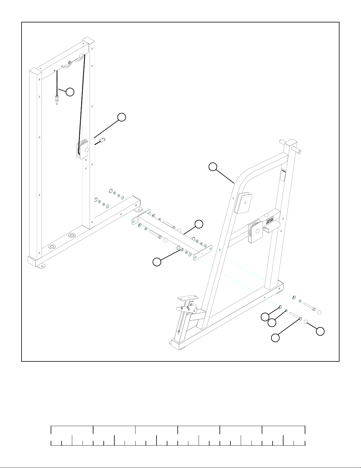
FIGURE 1
STEP 1:
• LOOSELY assemble the CROSS SUPPORT (2) to the T OWER (1) and the BOOM ASSEMBLY (4) using eight RH CAPS (41), four
3/8 X 3-3/4” BOLTS (15), eight 3/8” SAE WASHERS (21), eight 3/8” RH WASHERS (22) and four 3/8” LOW HEIGHT LOCK
NUTS (19) as shown in FIGURE 1.
1/2 1/2 1/2 1/2 1/2 1/2
0
1
2
345
4
6
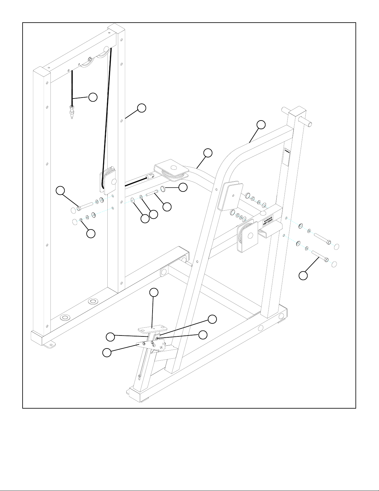
FIGURE 2
1A
1
4
5
12 3/8 X 2-1/2”
19
4E
4C
22
41
13 3/8 X 2-3/4”
21
13 3/8 X 2-3/4”
4A
4B
4D
STEP 2:
• LOOSELY assemble the CROSS BRACE (5) to the TOWER (1) and the BOOM ASSEMBLY (4) using seven RH CAPS (41), three
3/8 X 2-3/4” BOLTS (13), one 3/8 X 2-1/2” BOLT (12), seven 3/8” SAE WASHERS (21), seven 3/8” RH WASHERS (22) and
three 3/8” LOW HEIGHT LOCK NUTS (19) as shown in FIGURE 2.
• Securely tighten all loose frame connections made to this point and sanp on all RH CAPS (28,41)
and RH WASHERS (22).
5

CABLE
FIGURE 3
STEP 3:
• Carefully route the CABLE around the pulleys as shown. Make sure the CABLE is in the grooves of all the pulleys.
17 3/8 X 3-1/4”
23
40
1A
BUTTON HEAD
39
4
FIGURE 4
STEP 4:
• Slide two ACCORIDIAN SLEEVES (39) over the shafts on the BOOM ASSEMBLY (4) as shown in FIGURE 4.
• Slide two PILLOW BLOCKS (23) over the shafts on the BOOM ASSEMBLY (4) as shown in FIGURE 4.
• Assemble four 3/8 X 3-1/4” BUTTON HEAD CAP SCREWS (17) and four STARLOCK WASHERS (40) to the the PILLOW
BLOCKS (23)
as shown in FIGURE 4
1/2 1/2 1/2 1/2 1/2 1/2
0
1
2
345
6
6

23
TIGHTEN!
9
17 3/8 X 3-1/4”
BUTTON HEAD
22
21
19
9A
41
FIGURE 5
STEP 5:
• SECURELY assemble the PILLOW BLOCKS (23) to the SHOULDER ARM (9) using four previously inserted 3/8 X 3-1/4”
BUTTON HEAD CAP SCREWS (17), four 3/8” SAE WASHERS (21), four RH WASHERS (22), four 3/8” LOW HEIGHT
LOCK NUTS (19)
• IMPORTANT! When SHOULDER ARM (9) is centered and level in the PILLOW BLOCKS (23), tighten the PILLOW BLOCK set
screws.
and four RH CAPS (41) as shown in FIGURE 5
FIGURE 6
9
1A
STEP 6:
• SECURELY assemble one RUBBER BUMPER (6) to the BOOM ASSEMBLY (4) and the SHOULDER ARM (9) as shown in
FIGURE 6.
9A
6
4
7

FIGURE 7
9A
41
19
9
21
22
16 3/8 X 1-3/4”
3
STEP 7:
• SECURELY assemble the PULLEY BRACKET (3) to the SHOULDER ARM (9) using one 3/8 X 1-3/4” BOLT (16), two 3/8”
SAE WASHERS (21), two RH WASHERS (22), one AXLE (18), one 3/8” LOW HEIGHT LOCK NUTS (19)
(41) as shown in FIGURE 7
1/2 1/2 1/2 1/2 1/2 1/2
0
1
2
345
8
and two RH CAPS
6

FIGURE 8
4
19
3
29
18
22
21
3/8 X 3-1/4” 32
41
STEP 8:
• SECURELY assemble the two PULLEY BRACKETS (3) and one 4-1/2” PULLEY (29) to the bracket on the BOOM ASSEMBLY
(4) using one 3/8 X 3-1/4” BOLT (32), two 3/8” SAE WASHERS (21), two RH WASHERS (22), two AXLES (18), one 3/8”
LOW HEIGHT LOCK NUT (19)
and two RH CAPS (41) as shown in FIGURE 8.
9

19
1A
CABLE
9
CABLE DIAGRAM
22
21
41
3/8 X 1-3/4” 16
FIGURE 9
STEP 9:
• Carefully route the CABLE around the pulley as shown. Make sure the CABLE is in the grooves of all the pulley.
• Assemble the swivel end of the CABLE to the SHOULDER ARM (9) using one 3/8 X 1-3/4” BOLTS (16), two 3/8” SAE W ASHERS
(21), two RH WASHERS (22), one 3/8” LOW HEIGHT LOCK NUT (19)
Allow CABLE swivel end to rotate.)
1/2 1/2 1/2 1/2 1/2 1/2
0
1
2
345
10
and two RH CAPS (41) as shown in FIGURE 9. (NOTE:
6

35
4
3/8 X 3” 14
22
41
FIGURE 10
STEP 10:
• SECURELY assemble the BACK PAD (35) to the BOOM ASSEMBLY (4) using two RH CAPS (41), two 3/8 X 3” BOL TS (14) and
two 3/8” RH WASHERS (22) as shown in FIGURE 10.
11

36
4
22
3/8 X 1-1/4” 11
26
FIGURE 11
STEP 11:
• SECURELY assemble the SEAT PAD (36) to the BOOM ASSEMBLY (4) using two BLACK RH CAPS (26), two 3/8 X 1-1/4”
BOLTS (11) and two 3/8” RH WASHERS (22) as shown in FIGURE 11.
1/2 1/2 1/2 1/2 1/2 1/2
0
1
2
345
6
12
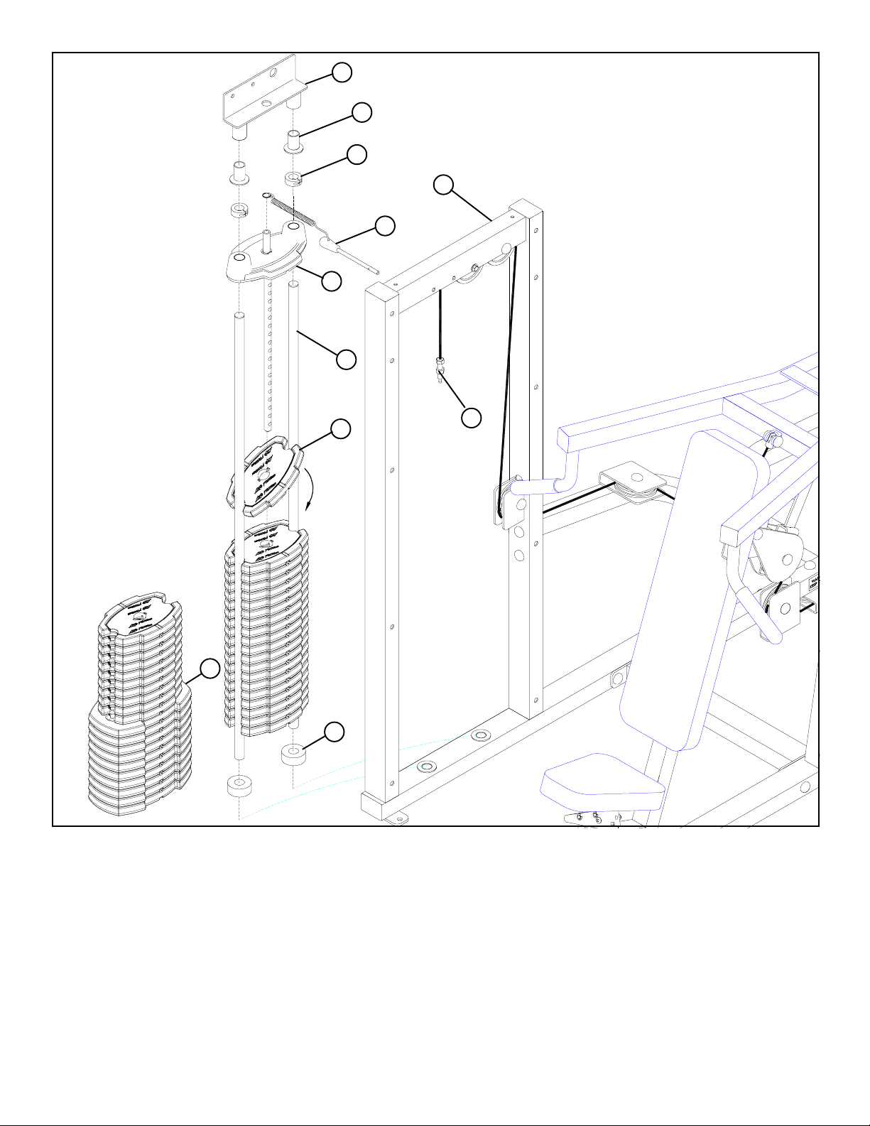
FIGURE 12
8
28
27
1
24
38
10
HEAVY WEIGHT
OPTION
34
25
33
1A
STEP 12:
• Insert the two GUIDE RODS (10) (found in the SHROUD KIT box) into the base of the TOWER (1) as shown in FIGURE 12.
Lubricate the GUIDE RODS (10) with a slicon or teflon spray that is available at most hardware stores.
• Slide two WEIGHT STACK CUSHIONS (25) down over the GUIDE RODS (10). See FIGURE 12.
• Using EXTREME CARE place twenty 10 LB. WEIGHT PLATES (33) over the GUIDE RODS (10). (NOTE: If HEA VY WEIGHT
OPTION is being used, slide ten 15LB. WEIGHT PLATES (34) over the GUIDE RODS (10) first, then slide ten 10 LB.
WEIGHT PLATES (33) over the GUIDE RODS.) .
• Carefully Slide the HEAD PLATE (38) down over the GUIDE RODS (10) onto the weight stack as shown in FIGURE 12.
• Slide one WEIGHT STACK SELECTOR PIN (24) over the shaft on the HEAD PLATE (38) as shown in FIGURE 12.
• Slide two 1” SHAFT COLLARS (27) over each GUIDE ROD (10) as shown in FIGURE 12.
• Slide two GUIDE ROD BUSHINGS (28) over each GUIDE ROD(10)
• Place the GUIDE ROD SUPPORT (8) over the GUIDE RODS (10) as shown in FIGURE 12.
13

FIGURE 13
41
12 3/8 X 2-1/2”
8
28
27
TIGHTEN!
1A
22
1
19
38
33
24
STEP 13:
• SECURELY assemble the GUIDE ROD SUPPORT (8) to the TOWER (1) using four RH CAPS (41), two 3/8 X 2-1/2” BOLTS
(12), four 3/8” RH WASHERS (22) and two 3/8” LOW HEIGHT LOCK NUTS (19) as shown in FIGURE 13.
• Slide GUIDE ROD BUSHINGS (28) into the tubes on the GUIDE ROD SUPPORT (8), slide 1” SHAFT COLLARS (27) under-
neath the GUIDE ROD BUSHINGS (28) and SECURELY tighten the set screws.
• Screw the threaded end of the CABLE all the way into the end of the shaft on the HEAD PLATE (38) and tighten jam nut
securely. See FIGURE 13.
• Insert the WEIGHT STACK PIN (24) into the WEIGHT STACK as shown in FIGURE 13.
1/2 1/2 1/2 1/2 1/2 1/2
0
1
2
345
14
6

FIGURE 14
38
33
37
STEP 14:
• The WEIGHT STACK LABEL sheet (37) includes labels for both lbs. and kgs. for both the standard and optional weight stacks.
• Peel the backing off the WEIGHT STACK LABELS (37), line up sheet to the right of the selector openning and apply labels to
the 10 LB.WEIGHT PLATES (33) and/or 15 LB. WEIGHT PLATES (34), starting with the HEAD PLATE (38) as shown in
FIGURE 14.
15

FIGURE 15
7
9
19
22
21
3/8 X 2-1/2” 12
41
STEP 15:
• SECURELY assemble two COUNTERBALANCES (7) to the SHOULDER ARM (9) using four RH CAPS (41), two 3/8 X 2-1/2”
BOL T (12), four 3/8” SAE WASHERS (21), four 3/8” RH WASHERS (22) and two 3/8” LOW HEIGHT LOCK NUT (19) as shown
in FIGURE 15.
• REFER TO SHROUD KIT ASSEMBLY INSTRUCTIONS.
1/2 1/2 1/2 1/2 1/2 1/2
0
1
2
345
16
6

30
31
42
45
43
44
FIGURE 16
STEP 16:
• Assemble the PLACARD LABEL (30) or the FOREIGN LANGUAGE PLACARD LABEL (31) to the FRONT SHROUD as shown
in FIGURE 16.
17

CAUTION-PLEASE READ
There is a risk assumed by individuals who use this type of equipment. To minimize risk, please
follow these rules:
1. Inspect equipment daily . T ighten all loose connections and replace worn parts immediately .
Failure to do so may result in serious injury .
2. Do not allow minors or children to play on or around this equipment.
3. Exercise with care to avoid injury .
4. Consult your physician before beginning any exercise program.
WARRANTY INFORMATION
10 YEARS STRUCTURUAL FRAME
3 YEARS PILLOW BLOCKS, PULLEYS, WEIGHT PLATES AND GUIDE RODS
1 YEAR CABLES
90 DAYS UPHOLSTERY
PREVENTATIVE MAINTENANCE TIPS
Action DAILY WEEKLY QUARTERLY BI-ANNUALLY AS NEEDED
CLEAN
Uphol s tery
Guide Rods
Hand Gri ps
INSPECT
Visual Overall
Cabl e s
Hardware
Frame
Hand Gri ps
LUBRICATE
Guide Rods
X
X
X
X
X
X
X
X
X
Clean:
• Upholstery with mild soap and water.
• Guide rods with a cotton cloth.
• Hand grips with mild soap and water.
• Frame damage can be repaired with touch-up paint can be purchased from your LifeFitness customer service representative at
(800) 351-3737.
Inspect:
• Cables for wear or damage and proper tension (should not exceed 3/4” deflection.) Pay close attention at bends and attachment
points.
• Hardware should be checked for looseness. Tighten as required.
• Frames should be inspected for wear or damage.
• Hand Grips should be checked for wear or damage
Lubricate:
• Lube the Guide Rods. Apply the lubricant to a cotton cloth, then run the cotton cloth up and down the guide rods as needed. Do not
spray lubricant directly on the Guide Rods.
Thank you for purchasing the LifeFitness CLUB SERIES SHOULDER PRESS. If unsure of proper use of
equipment, call your local LifeFitness distributor or call the LifeFitness customer service department at
(800) 351-3737.
18
 Loading...