

Page 1
CLUB SERIES ADJUST ABLE BENCH
Part # 7147801
Rev C.
ASSEMBLY INSTRUCTIONS
Revision:9/18/011
Page 2
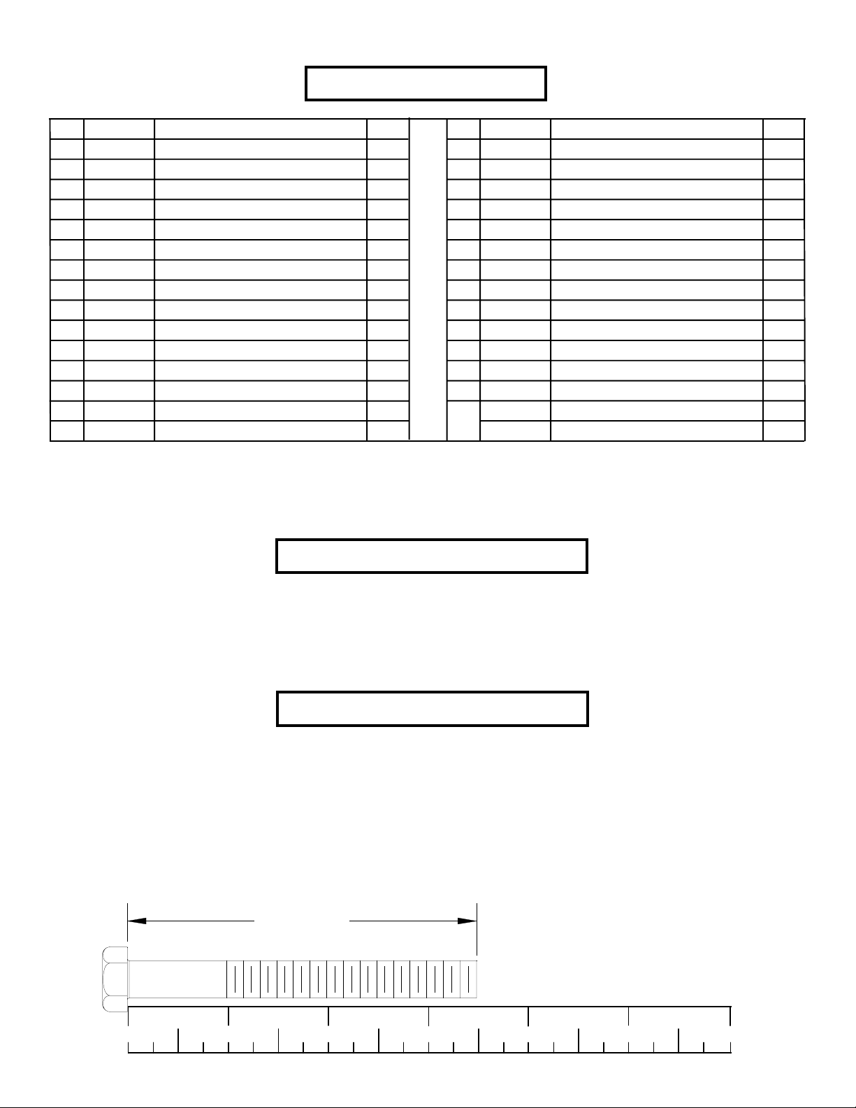
PARTS LIST
KEY
1
2
3
4
5
6
7
8
9
10
11
12
13
14
PART #
71447
71446
71443
71444
71445
71315
69131xx
69132xx
69307xx
3102941
3102922
3102904
3102905
3102906
DESCRIPTION
BENCH FRAME
BACK P AD SUPPOR T
BACK P AD ADJUST
3 X 2 X 18” TUBE
REAR UPRIGHT
BACK P AD ADJUST PLA TE
SEA T P AD
LUMBAR P AD
BACK P AD
3/8 X 1-1/2” BOLT
3/8 X 2-3/4” BOLT
3/8 X 3” BOLT
3/8 X 3-3/4” BOLT
3/8 X 4” BOLT
QTY
1
1
2
1
1
2
1
1
1
2
4
4
3
1
KEY
15
16
17
18
19
20
21
22
23
24
25
26
27
28
OR
PART #
3223320
3202406
3102807
3102514
3228501
3104901
7131002
7131001
7145501
6866701
3116001
6866601
6535501
6866602
6866603
DESCRIPTION
3/8 X 6-1/2” BOLT
3/8 X 1-1/4” BUTTON HEAD BOLT
3/8” LOW HEIGHT LOCK NUT
3/8” SAE WASHER
3/8” BLACK SAE WASHER
3/4” FLANGE BEARING
3/4 X 3” PIVOT SHAFT
3/4 X 5-5/16” PIVOT SHAFT
3/4 X 5-5/16” CHROME PIVOT SHAFT
3/8” RH WASHER
1-1/4” SQ. RUBBER BUMPER
BLACK RH CAP
3” WHEEL
WHITE RH CAP
PLA TINUM RH CAP
QTY
2
2
12
10
2
4
1
1
1
28
2
6
2
22
22
T ools Required for Assembly
* Rubber mallet or hammer
* 9/16” wrench
* Ratchet with 9/16” socket
* 7/32” Allen wrench
Bolt Length Ruler
NOTE: BOL T LENGTH IS MEASURED FROM THE UNDERSIDE OF THE HEAD OF THE BOLT.
BOLT LENGTH
1/2 1/2 1/2 1/2 1/2 1/2
0
1
2
345
2
6
Page 3
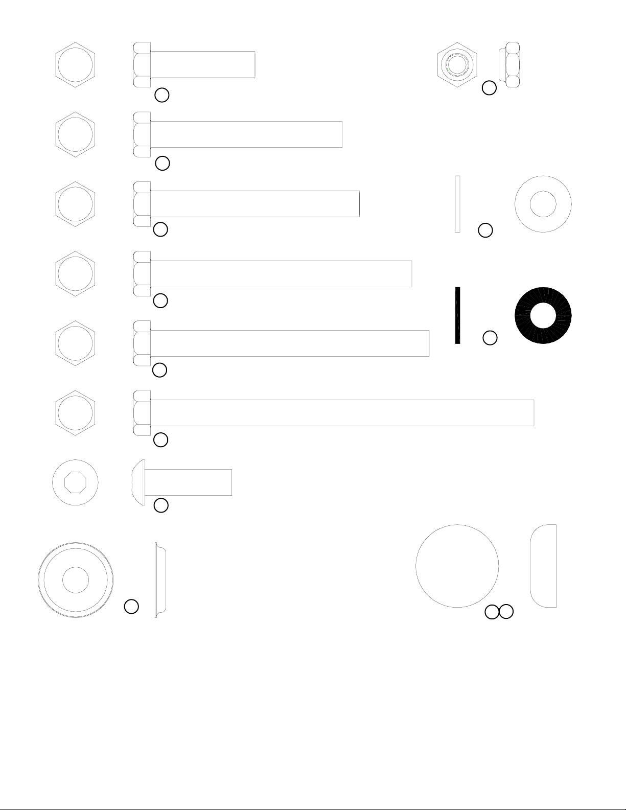
10 3/8 X 1-1/2” BOLT
11 3/8 X 2-3/4” BOLT
17
3/8” LOW
HEIGHT LOCK
NUT
12 3/8 X 3” BOLT
13 3/8 X 3-3/4” BOLT
14 3/8 X 4” BOLT
15 3/8 X 6-1/2” BOLT
16 3/8 X 1-1/4” BUTTON HEAD BOLT
18
3/8” SAE
WASHER
19
3/8” BLACK SAE
WASHER
24
RH
WASHER
28
26
RH CAP
(BLACK/WHITE/PLATINUM)
3
Page 4

FIGURE 1
1
5
24
17
18
4
28
11 3/8 X 2-3/4”
STEP 1:
• SECURELY assemble the 3 X 2 X 18” TUBE (4) and the REAR UPRIGHT (5) to the BENCH FRAME (1) using eight RH CAPS
(28), four 3/8 X 2-3/4” BOLTS (11), eight 3/8” SAE WASHERS (18), eight 3/8” RH WASHERS (24) and four 3/8” LOW
HEIGHT LOCK NUTS (17) as shown in FIGURE 1.
2
17
25
1
24
18
21
20
FIGURE 2
14 3/8 X 4”
28
STEP2:
• SECURELY assemble the BACK PAD SUPPORT (2) to the BENCH FRAME (1) using two RH CAPS (28), one 3/8 X 4” BOLT
(14), one 3/4” X 3” PIVOT SHAFT (21), two 3/4” FLANGE BEARINGS (20), two 3/8” SAE WASHERS (18), two 3/8” RH
WASHERS (24) and one 3/8” LOW HEIGHT LOCK NUT (17) as shown in FIGURE 2.
• Assemble two 1-1/4” RUBBER BUMPERS (25) to where the BACK PAD SUPPORT (2) contacts the BENCH FRAME (1).
4
Page 5

FIGURE 3
17
1
6
24
13 3/8 X 3-3/4”
26
STEP 3:
• SECURELY assemble the BACK PAD ADJUST PLATES (6) to the BENCH FRAME (1) using six BLACK RH CAPS (26), three 3/
8 X 3-3/4” BOLTS (13), six 3/8” RH WASHERS (24) and three 3/8” LOW HEIGHT LOCK NUTS (17) as shown in FIGURE 3.
17
3
23 CHROME
22
2
20
3
FIGURE 4
24
3/8 X 6-1/2” 15
28
STEP 4:
• SECURELY assemble two BACK PAD ADJUSTS (3) to the BACK PAD SUPPORT (2) using two RH CAPS (28), one 3/8 X 6-
1/2” BOLT (15), one 3/4” X 5-5/16” PIVOT SHAFT (22), two 3/4” FLANGE BEARINGS (20), two 3/8” RH WASHERS (24)
and one 3/8” LOW HEIGHT LOCK NUT (17) as shown in FIGURE 4.
• SECURELY assemble one 3/4” X 5-5/16” CHROME PIVOT SHAFT (23) between the two BACK PAD ADJUSTS (3) using
two RH CAPS (28), one 3/8 X 6-1/2” BOLT (15), two 3/8” RH WASHERS (24) and one 3/8” LOW HEIGHT LOCK NUT (17)
as shown in FIGURE 4.
1/2 1/2 1/2 1/2 1/2 1/2
0
1
2
345
6
5
Page 6

FIGURE 5
7
1
24
3/8 X 3” 12
28
STEP 5:
• SECURELY assemble the SEAT PAD (7) to the BENCH FRAME (1) using two RH CAPS (28), two 3/8 X 3” BOLTS (12) and
two 3/8” RH WASHERS (24) as shown in FIGURE 5.
3”
8
2
19 BLACK
16 3/8 X 1-1/4” BUTTON
HEAD BOL T
FIGURE 6
STEP 6:
• SECURELY assemble the LUMBAR PAD (8) to the BACK PAD SUPPORT (2) using two 3/8 X 1-1/4” BUTTON HEAD BOLTS
(16) and two 3/8” BLACK SAE WASHERS (19) as shown in FIGURE 6. (Note direction of PAD.)
6
Page 7

FIGURE 7
9
2
24
12 3/8 X 3”
28
STEP 7:
• SECURELY assemble the BACK PAD (9) to the BACK PAD SUPPORT (2) using two RH CAPS (28), two 3/8 X 3” BOLTS (12)
and two 3/8” RH WASHERS (24) as shown in FIGURE 7.
FIGURE 8
5
17
STEP 8:
• SECUREL Y assemble two 3” WHEELS (27) to the REAR UPRIGHT (5) using four RH CAPS (28), two 3/8 X 1-1/2” BOLTS (10),
four 3/8” RH WASHERS (24) and two 3/8” LOW HEIGHT LOCK NUTS (17) as shown in FIGURE 8. (NOTE: T ighten connec-
tion enough to allow wheels to rotate freely, do not over tighten.)
1/2 1/2 1/2 1/2 1/2 1/2
0
1
2
345
27
24
10 3/8 X 1-1/2”
28
6
7
Page 8

CAUTION-PLEASE READ
There is a risk assumed by individuals who use this type of equipment. To minimize risk, please
follow these rules:
1. Inspect equipment daily . Tighten all loose connections and replace worn parts immediately .
Failure to do so may result in serious injury.
2. Do not allow minors or children to play on or around this equipment.
3. Exercise with care to avoid injury .
4. Consult your physician before beginning any exercise program.
WARRANTY INFORMATION
10 YEARS STRUCTURUAL FRAME
3 YEARS PILLOW BLOCKS, PULLEYS, WEIGHT PLA TES AND GUIDE RODS
1 YEAR CABLES
90 DA YS UPHOLSTERY
PREVENTATIVE MAINTENANCE TIPS
Action DAILY WEEKLY QUARTERLY BI-ANNUALLY AS NEEDED
CLEAN
Uphol s tery
Guide Rods
Hand Grips
INSPECT
Visual Overall
Cabl e s
Hardware
Frame
Hand Grips
LUBRICATE
Guide Rods
X
X
X
X
X
X
X
X
X
Clean:
• Upholstery with mild soap and water.
• Guide rods with a cotton cloth.
• Hand grips with mild soap and water.
• Frame damage can be repaired with touch-up paint can be purchased from your LifeFitness customer service representative at
(800)351-3737.
Inspect:
• Cables for wear or damage and proper tension (should not exceed 3/4” deflection.) Pay close attention at bends and attachment
points.
• Hardware should be checked for looseness. Tighten as required.
• Frames should be inspected for wear or damage.
• Hand Grips should be checked for wear or damage
Lubricate:
• Lube the Guide Rods. Apply the lubricant to a cotton cloth, then run the cotton cloth up and down the guide rods as needed. Do not
spray lubricant directly on the Guide Rods.
Thank you for purchasing the LifeFitness CLUB SERIES ADJUST ABLE BENCH. If unsure of pr oper use
of equipment, call your local LifeFitness distributor or call the LifeFitness customer service department at
(800) 351-3737.
8
 Loading...