

Page 1
CLUB SERIES ADJUSTABLE AB BENCH
Part # 7320301
Rev C.
ASSEMBLY INSTRUCTIONS
Revision: 11/18/021
Page 2
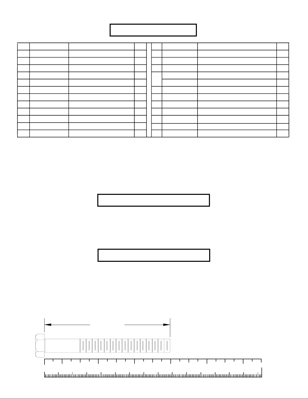
PARTS LIST
NOTICE: ALL PART NUMBERS NEED ACU ADDED TO THE NUMBER.
FOR INSTANCE; ACUP07-0005
KEY
1
2
3
4
5
6
7
8
9
10
11
12
AP04-0013
AP04-0014
AP04-0012
AP01-0032
AP04-0023
DA1C03817016NU
DA1C03806816NU
DA1C03808316NU
DA1C03816416NU
PART #
P04-0011
P07-0005
P07-0002
DESCRIPTION
SEAT
FRAME
P AD ADJUST
BASE
19-1/4” ROLLER PAD TUBE
SEA T PAD
BENCH P AD
REAR BASE
3/8 X 170mm BOL T
3/8 X 68mm BOL T
3/8 X 83mm BOL T
3/8 X 164mm BOL T
QTY
1
1
2
1
2
1
1
1
2
4
4
1
KEY
13
14
15
16
OR
17
18
19
20
21
22
PART #
DB2E03807200NU
DC120010510U
P05-0009
P06-0021
P06-0021
P06-0012
P06-0005
P06-0013
P06-0007
P06-0006
P03-0004
DESCRIPTION
3/8” LOW HEIGHT LOCK NUT
3/8” SAE WASHER
3/8” RH WASHER
WHITE RH CAP
PLA TINUM RH CAP
1-1/4” SHAFT COLLAR
5 X 8” ROLLER P AD
2-3/8” OD PLASTIC W ASHER
2” SQ. END CAP
3 X 2” END CAP
3/4 X 5-5/16” CHROME PIVOT SHAFT
QTY
7
18
18
18
18
4
4
8
1
1
1
T ools Required for Assembly
* 9/16” wrench
* Ratchet with 9/16” socket
* 3mm Allen wrench (Supplied)
* 4mm Allen wrench (Supplied)
Bolt Length Ruler
NOTE: BOL T LENGTH IS MEASURED FROM THE UNDERSIDE OF THE HEAD OF THE BOL T .
BOLT LENGTH
0
1/2 1/2 1/2 1/2 1/2 1/2
10 20 30 40 50 60 70 80 90 100 110 120 130 140 150
1
23456
2
Page 3

10 3/8 X 68mm BOL T
11 3/8 X 83mm BOL T
12 3/8 X 164mm BOL T
9 3/8 X 170mm BOL T
13
3/8” LOW
HEIGHT LOCK
NUT
14
3/8” SAE
WASHER
15
RH
WASHER
16
RH CAP
(WHITE/PLATINUM)
3
Page 4

FIGURE 1
8
13
14
15
2
4
16
10 3/8 X 68mm
10 3/8 X 68mm
STEP 1:
• SECUREL Y assemble the BASE (4) to the FRAME (2) using four RH CAPS (16), two 3/8 X 68mm BOLTS (10), four 3/8” SAE
W ASHERS (14), four 3/8” RH W ASHERS (15) and two 3/8” LOW HEIGHT LOCK NUTS (13) as shown in FIGURE 1.
• SECURELY assemble the REAR BASE (8) to the FRAME (2) using four RH CAPS (16), two 3/8 X 68mm BOL TS (10), four 3/8” SAE
W ASHERS (14), four 3/8” RH W ASHERS (15) and two 3/8” LOW HEIGHT LOCK NUTS (13) as shown in FIGURE 1.
4
Page 5

13
1
2
15
14
12 3/8 X 164mm
16
FIGURE 2
STEP 2:
• SECURELY assemble the SEA T (1) to the FRAME (2) using two RH CAPS (16), one 3/8 X 164mm BOLT (12), two 3/8” SAE W ASH-
ERS (14), two 3/8” RH WASHERS (15) and one 3/8” LOW HEIGHT LOCK NUT (13) as shown in FIGURE 2.
5
Page 6

FIGURE 3
13
1
3
22 CHROME
14
15
3/8 X 170mm 9
16
STEP 3:
• SECURELY assemble two P AD ADJUSTS (3) to the SEAT (1) using two RH CAPS (16), one 3/8 X 170mm BOL T (9), two 3/8” SAE
W ASHERS (14), two 3/8” RH WASHERS (15) and one 3/8” LOW HEIGHT LOCK NUT (13) as shown in FIGURE 3.
• SECURELY assemble one 3/4” X 5-5/16” CHROME PIVOT SHAFT (22) between the two PAD ADJUSTS (3) using two RH
CAPS (16), one 3/8 X 170mm BOL T (9), two 3/8” SAE WASHERS (14), two 3/8” RH WASHERS (15) and one 3/8” LOW HEIGHT
LOCK NUT (13) as shown in FIGURE 3.
6
Page 7

FIGURE 4
6
1
7
15
14
3/8 X 83mm 11
16
STEP 4:
• SECURELY assemble the SEA T P AD (6) to the SEA T (1) using two RH CAPS (16), two 3/8 X 83mm BOL TS (11), two 3/8” SAE
W ASHERS (14) and two 3/8” RH W ASHERS (15) as shown in FIGURE 4.
• SECURELY assemble the BACK P AD (7) to the SEA T (1) using two RH CAPS (16), two 3/8 X 83mm BOLTS (11), two 3/8” SAE
W ASHERS (14) and two 3/8” RH W ASHERS (15) as shown in FIGURE 4.
7
Page 8

FIGURE 5
21
SET SCREWS
20
1
SET SCREWS
SERIAL #
LOCA TION
5
19
18
17
STEP 5:
• Assemble four 5 X 8” ROLLER PADS (18) to the SEAT (1) using four 1-1/4” SHAFT COLLARS (17), eight 2-3/8” OD PLASTIC
WASHERS (19) and two 19-1/4” ROLLER PAD TUBES (5) as shown in FIGURE 5. Once the ROLLER PADS (18) are assembled
to the SEAT (1), SECURE the 19-1/4” ROLLER PAD TUBES (5) in place using the four SET SCREWS in the tubes on the SEAT
(1) as shown in FIGURE 5..
• Insert one 3 X 2” END CAPS (21) and one 2” SQ. END CAP (20) into the BASE (1) as shown in FIGURE 5.
8
Page 9

CAUTION-PLEASE READ
There is a risk assumed by individuals who use this type of equipment. To minimize risk, please
follow these rules:
1. Inspect equipment daily . T ighten all loose connections and replace worn parts immediately.
Failure to do so may result in serious injury.
2. Do not allow minors or children to play on or around this equipment.
3. Exercise with care to avoid injury .
4. Consult your physician before beginning any exercise program.
WARRANTY INFORMA TION
10 YEARS STRUCTURUAL FRAME
3 YEARS PILLOW BLOCKS, PULLEYS, WEIGHT PLATES AND GUIDE RODS
1 YEAR CABLES
90 DA YS UPHOLSTERY
PREVENT ATIVE MAINTENANCE TIPS
Action DAILY WEEKLY QUARTERLY BI-ANNUALLY AS NEEDED
CLEAN
Uphol s tery
Guide Rods
Hand Grips
INSPECT
Visual Overall
Cabl e s
Hardware
Frame
Hand Grips
LUBRICATE
Guide Rods
X
X
X
X
X
X
X
X
X
Clean:
• Upholstery with mild soap and water.
• Guide rods with a cotton cloth.
• Hand grips with mild soap and water.
• Frame damage can be repaired with touch-up paint can be purchased from your LifeFitness customer service representative at
(800)351-3737.
Inspect:
• Cables for wear or damage and proper tension (should not exceed 3/4” deflection.) Pay close attention at bends and attachment
points.
• Hardware should be checked for looseness. Tighten as required.
• Frames should be inspected for wear or damage.
• Hand Grips should be checked for wear or damage
Lubricate:
• Lube the Guide Rods. Apply the lubricant to a cotton cloth, then run the cotton cloth up and down the guide rods as needed. Do not
spray lubricant directly on the Guide Rods.
Thank you for purchasing the LifeFitness CLUB SERIES ADJUSTABLE AB BENCH. If unsure of
proper use of equipment, call your local LifeFitness distributor or call the LifeFitness customer service
department at (800) 351-3737.
9
 Loading...