

Ab Crunch Bench
Owner’s Manual
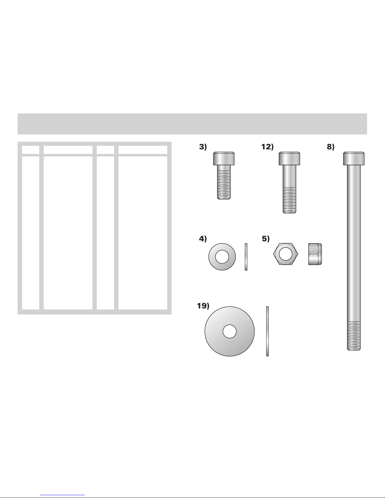
Tools Required:
O
8mm Allen Wrench
O
17mm Wrench
O
Ratchet
O
3” Ratchet Extension
O
17mm Socket
O
8mm Hex Bit
Ab Crunch Bench
1. Assembly Instructions
Qty
1
1
13
21
12
1
1
2
1
1
1
5
12
1
1
1
2
1
1
1
Description
Lower Support
Cam Follower
Screw, M10 X 25mm
3/8” Flat Washer
Nylock Nut
Work Arm Stop
Cross Member
Screw, M10 X 135mm
Foot Rest
Back Support
Pad, Large Back
Screw, M10 X 35mm
1" Hole Plug
Pad, Arm Rest
Pad, Shoulder
Work Arm
Ball Bearing
Internal Spacer
3/8" Fender Washer
Bearing Housing Cap
Part Number
LEA78096XX
LEA78093XX
LEA3251702
LEA3102514
LEA3242002
LEA78099XX
LEA78097XX
LEA3251721
LEA78094XX
LEA78095XX
LEA74741XX
LEA3251704
LEA3237403
LEA73933XX
LEA74689XX
LEA78098XX
LEA3235601
LEA7799501
LEA3252001
LEA7308701
Item
1
2
3
4
5
6
7
8
9
10
11
12
13
14
15
16
17
18
19
20
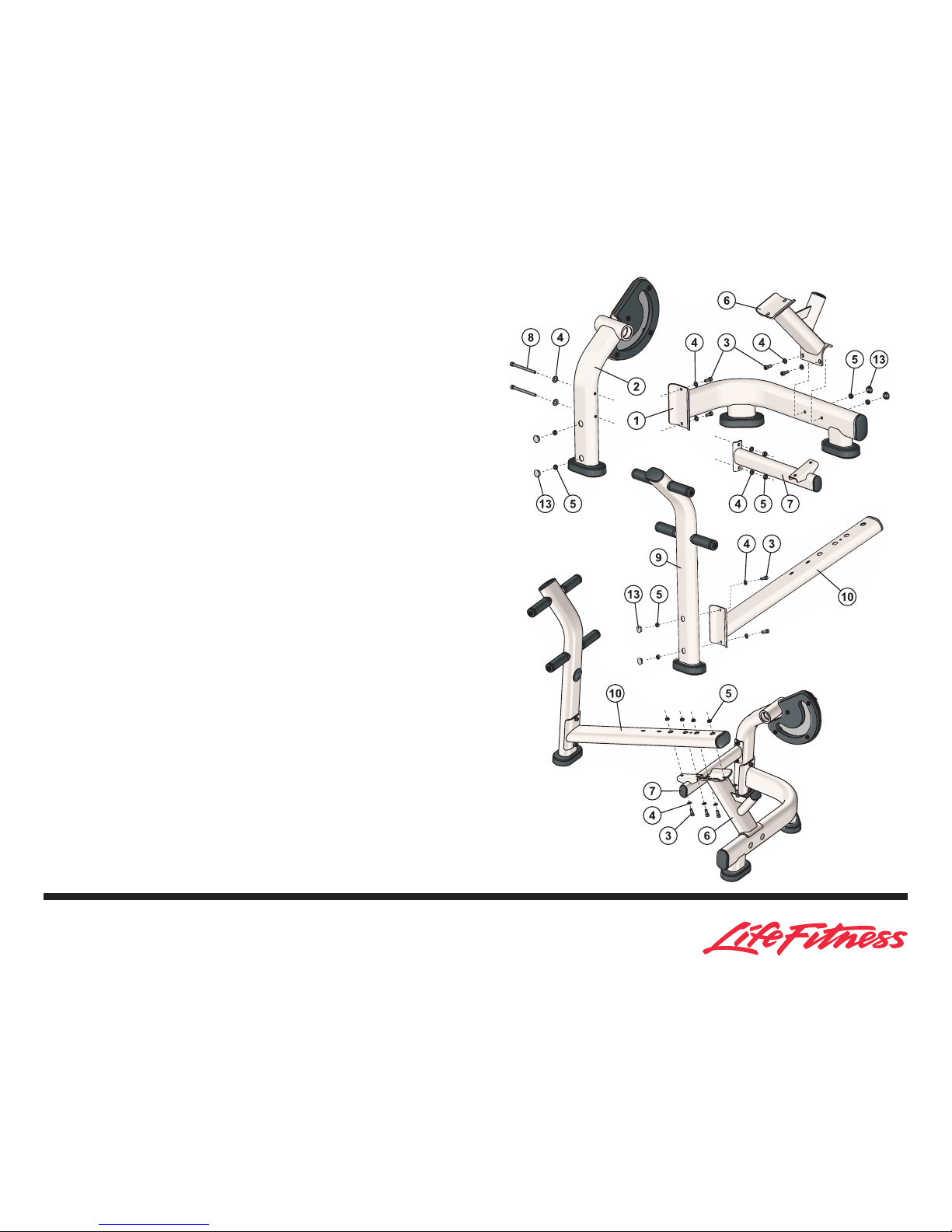
1. Locate the LOWER SUPPORT (1) and the CAM FOLLOWER (2). Using two
M10 x 25mm BOLTS (3), FLAT WASHERS (4), and NYLOCK NUTS (5),
secure the LOWER SUPPORT to the CAM FOLLOWER. Loosely tighten
the BOLTS and NUTS.
2. Locate the WORK ARM STOP (6). With the WORK ARM STOP positioned
as shown, align the mounting holes and secure the WORK ARM STOP to
the LOWER SUPPORT (1) using two M10 x 25mm BOLTS (3), FLAT
WASHERS (4), and NYLOCK NUTS (5). Loosely tighten the BOLTS and
NUTS.
3. Locate the CROSSMEMBER (7). With the CROSSMEMBER positioned as
shown, align the mounting holes and secure the CROSSMEMBER to the
CAM FOLLOWER (2) using two M10 x 135mm BOLTS (8), four FLAT
WASHERS (4), and two NYLOCK NUTS (5). Loosely tighten the BOLTS
and NUTS.
4. Locate the FOOT REST (9) and BACK SUPPORT (10). Position the FOOT
REST and BACK SUPPORT as shown. Align the mounting holes and
secure the FOOT REST to the BACK SUPPORT using two M10 x 25mm
BOLTS (3), FLAT WASHERS (4), and NYLOCK NUTS (5). Loosely tighten
the BOLTS and NUTS.
5. Position the BACK SUPPORT (10) over the WORK ARM STOP (6) and
CROSSMEMBER (7) as shown. Align the mounting holes and secure the
BACK SUPPORT to the WORK ARM STOP and CROSSMEMBER using
four M10 x 25mm BOLTS (3), FLAT WASHERS (4), and NYLOCK NUTS
(5). Tighten the BOLTS securely.

6. Locate the LARGE BACK PAD (11). Position the LARGE BACK PAD over
the BACK SUPPORT (10) as shown. Align the mounting holes and secure
the LARGE BACK PAD to the BACK SUPPORT using three M10 x 35mm
BOLTS (12) and FLAT WASHERS (4). Tighten the BOLTS securely. Cover
the BOLT access holes with three HOLE PLUGS (13).
7. Locate the HEADREST (14). Position the HEADREST onto the HEADREST
BRACKET (A) as shown. Align the mounting holes and secure the HEADREST using two M10 x 25mm BOLTS (3) and FLAT WASHERS (4).
Tighten the BOLTS securely.
8. Locate the SHOULDER PAD (15). Position the SHOULDER PAD over the
WORK ARM (16) as shown. Align the mounting holes and secure the
SHOULDER PAD using two M10 x 35mm BOLTS (12) and FLAT WASHERS (4). Tighten the BOLTS securely.
9. Slide one BEARING (17) over the PIVOT POST (B). Slide the SPACER (18)
over the PIVOT POST. Slide the PIVOT POST through the PIVOT HUB (C)
until the BEARING is fully seated. Slide a second BEARING over the
exposed end of the PIVOT POST until fully seated into the PIVOT HUB.
Secure the PIVOT POST into the PIVOT HUB using the M10 x 25mm
BOLTS (3) and FENDER WASHER (19), Tighten the BOLT securely. Cover
the exposed end of the PIVOT HUB with the PIVOT HUB CAP (20)
.
10. Tighten all remaining BOLTS securely. Cover all remaining open BOLT
access holes with HOLE PLUGS (13).
Ab Crunch Bench
1. Assembly Instructions

It is the sole responsibility of the purchaser of Life Fitness products to instruct all individuals, whether they are the end user or supervising personnel on
proper usage of the equipment.
It is recommended that all users of Life Fitness exercise equipment be informed of the following information prior to its use.
PROPER USAGE
1. Do not use any equipment in any way other than designed or intended by the manufacturer. It is imperative that all Life Fitness equipment is used
properly to avoid injury.
2. Keep hands and feet clear at all times from moving parts to avoid injury.
3. It is the purchaser's sole responsibility to properly instruct end users and supervising personnel as to the proper operating procedures of all Life
Fitness equipment.
CHECK FOR DAMAGED PARTS
1. DO NOT use any equipment that is damaged and or has worn or broken parts. Use only replacement parts supplied by Life Fitness.
2. MAINTAIN LABELS AND NAMEPLATES. Do not remove labels for any reason. They contain important information. If unreadable or missing, con-
tact LIFE FITNESS for a replacement.
3. SECURE EQUIPMENT. All equipment MUST be secured to the floor to stabilize and eliminate rocking or tipping over. This must be performed by a
licensed contractor.
4. Ensure that any person(s) making adjustments or performing maintenance or repair of any kind is qualified to do so. Life Fitness will provide serv-
ice and maintenance training at our corporate facility upon request or in the field if appropriate arrangements are made.
SPECIFIC OPERATING WARNINGS
1. Do not allow users to wear loose fitting clothing while using equipment. It is also recommended to have users secure long hair back and up to
avoid contact with moving parts.
2. It is the purchaser's sole responsibility to properly instruct end users and supervising personnel as to the proper operating procedures of all Life
Fitness equipment.
3. Keep children away from strength equipment. Parent or others supervising children must provide close supervision of children if the equipment is
used in the presence of children.
4. Use Olympic Weight Plates to incrementally increase resistance. Never use dumbbells or other means to incrementally increase weight resistance.
5. UNDERSTANDING EACH AND EVERY WARNING TO THE FULLEST EXTENT IS IMPORTANT. IF ANY OF THESE WARNINGS ARE UNCLEAR, ASK
FOR CLARIFICATION FROM LIFE FITNESS PERSONNEL.
6. It is recommended that all individuals consult a physician prior to commencing an exercise program. If at any time during exercise a exerciser
feels faint, dizzy or experience pain, he/she should stop and consult a physician.
Abdominal Crunch
2. Safety & Warranty

WARRANTY
WHAT IS COVERED
This Life Fitness commercial exercise equipment (Ab Crunch Bench) is warranted to be free of all defects in material and workmanship.
WHO IS COVERED
The manufacturer’s warranty covers the original purchaser or any person receiving the Product as a gift from the original purchaser.
WHO PAYS TRANSPORTATION & INSURANCE FOR SERVICE
If the Product or any covered part must be returned to a service facility for repairs, Life Fitness, will pay all transportation and insurance charges for the
first year. The purchaser is responsible for transportation and insurance charges during the second and third years (if applicable).
WHAT WE WILL DO TO CORRECT COVERED DEFECTS
Life Fitness will ship any new or rebuilt replacement parts or components, or, at the option of Life Fitness, replace the Product. Such replacement parts are
warranted for the remaining portion of the original warranty period.
WHAT IS NOT COVERED
Any failures or damage caused by unauthorized service, misuse, accident, negligence, improper assembly or installation, debris resulting from any construction activities in the Product's environment, rust or corrosion as a result of the Product's location, alterations or modifications without our written
authorization or by failure on the purchaser’s part to use, operate and maintain the Product as set out in your Owner’s Manual (.Manual.). All terms of this
warranty are void if this Product is moved beyond the continental borders of the United States of America (excluding Alaska, Hawaii and Canada) and are
then subject to the terms provided by that country's local authorized Life Fitness representative.
OWNER’S MANUAL
It is VERY IMPORTANT THAT YOU READ THIS MANUAL before operating the Product. Remember to perform the periodic maintenance specified in the
Manual to assure proper operation and continued satisfaction with the Product.
HOW TO GET PARTS & SERVICE
Call Customer Support Services at (800) 351-3737 or (847) 451-0036, Monday through Friday from 8:00 a.m. to 6:00 p.m. Central Standard Time. Have the
following information available when calling; name, address and serial number of the Product. Life Fitness will provide information on how to obtain a
replacement part, advice on how and where to ship the Product for service or, if necessary, arrange for on-site service.
Before shipping the Product:
1. Obtain a Return Authorization Number (RA#) from Customer Support Services
2. Securely pack your Product (use the original shipping carton, if possible)
3. Write the RA# on the outside of the carton
4. Insure the Product, and
5. Include a letter explaining the defect or problem and a copy of the proof of purchase if you believe the service is covered by warranty.
Ab Crunch Bench
2. Safety & Warranty

EXCLUSIVE WARRANTY
THIS LIMITED WARRANTY IS IN LIEU OF ALL OTHER WARRANTIES OF ANY KIND EITHER EXPRESSED OR IMPLIED, INCLUDING BUT NOT LIMITED TO
THE IMPLIED WARRANTIES OF MERCHANTABILITY AND FITNESS FOR A PARTICULAR PURPOSE, AND ALL OTHER OBLIGATIONS OR LIABILITIES ON
THE PART OF LIFE FITNESS. Life Fitness neither assumes nor authorizes any person to assure for Life Fitness any other obligation or liability concerning
the sale of this Product. Under no circumstances shall Life Fitness be liable under this warranty, or otherwise, of any damage to any person or property,
including any lost profits or lost savings, for any special, indirect, secondary, incidental or consequential damages of any nature arising out of the use of or
inability to use this Product. Some states do not allow the exclusion or limitation of implied warranties or of liability for incidental or consequential damages, so the above limitations or exclusions may not apply in those instances.
CHANGES IN WARRANTY NOT AUTHORIZED
No one is authorized to change, modify or extend the terms of this limited warranty.
EFFECT OF STATE LAWS
This warranty gives you specific legal rights and you may have other rights, which vary, from state to state.
THE LIFE FITNESS PLEDGE TO YOU
Life Fitness Products are designed and manufactured to the highest standards.
Life Fitness wants its customers to be completely satisfied with the its Product and will do everything possible under the terms of this warranty to keep its
customers secure in knowing they have bought the best!

General Specifications
1. Frame Construction
Frame is constructed of mechanical quality steel purchased in mill run quantities.
Frame is primarily 2 ½" x 4 ½" oval-shaped tubing with 11 gauge wall thickness.
2. Frame Finish
Prior to applying finish, each part is chemically washed to prepare surface for maximum adhesion.
3. Weight Horn
Weight horn under the head pad gives users the ability to increase resistance with Olympic weight plates. This allows flexibility for all users in all
phases of their training.
4. Cam
The cam is CNC machined from solid polymer and designed to match the appropriate muscle strength capability curve.
5. Integral Bearings
Bearings are sealed bearings with a basic radial load rating of over 2,000 pounds. Bearings are mounted within precision-machined housings for
optimal alignment, which results in smooth and friction free movement.
6. Bolts
All hardware is metric and has a corrosion resistant finish.
7. Upholstery
Contoured pads.
All edges are stitched to eliminate any folds in the material that would limit durability.
8. Foam
Three and four pound EVA foam (deformation resistant) or equivalent is used on all machines. The foam is injection molded directly to the multiply wood support board with integral 10mm T-nuts.
9. Hand Grips
Hand grips are an extruded 60-durometer-thermorubber compound that is non-absorbing, wear and tear resistant, and exhibits good dry and wet
frictional characteristics.
The grips are retained with aluminum collars, which eliminate the tendency of the grips to slide off the handle.
10. Foot Platforms
Foot platforms are molded rubber with a slip resistant texture.
Ab Crunch Bench
3. Specifications

11. Instructional Placard
Visual placard provides illustration for proper use.
12. Equipment Anchoring
All machines have holes in the feet, which allow for easy anchoring to the floor. Life Fitness recommends that all machines be anchored to the
floor to minimize the possibility of tipping.
13. Warranty
10-year minimum warranty on frames, 5 years on integral bearings, 1 year on grips, and 90 days on upholstery and any items not specified.
14. Liability Insurance
Certificate of insurance available upon request.
Product Specifications
AB CRUNCH BENCH Product # - SABC
Machine Weight: 141 lbs. 64 kg.
Size: in = 64L x 32W x 42H cm = 163 L x 81 W x 107 H
Live Area: in = 72L x 50W x 42H cm = 183 L x 127 W x 107 H
O
Dual cam mechanism creates a natural crunch style movement for effective abdominal contraction minimizing hip flexor assistance.
O
Bench design is optimized for easy entry/exit and greater stabilization.
O
Contoured cushions utilize a molded foam for greater comfort.
O
Standard weight horn allows users to add resistance.

Muscles Exercised -Abdominals
Setup
Check weight horn for appropriate resistance. Lay down on Ab Crunch
Bench with head near the top of the head pad and shoulders flat on the middle pad. Grasp handles and place feet on the foot pegs that are most comfortable.
Performing the Exercise
Grasp handles and slowly contract abdominals until body is in a crunch position. Slowly return to start position and repeat without letting the movement
arm rest on its support.
Ab Crunch Bench
4. Exercise
Start Finish

ONCE A DAY
O
Wipe down upholstery with a mild soap and water or comparable all purpose cleaner.
ONCE A WEEK
O
Visually inspect all hardware for loosening, tampering or wear.
O
Check condition of hand grips.
ONCE A MONTH
O
Inspect hardware and tighten any bolts or nuts that may have loosened during use.
ACTION DAILY MONTHLY BI-ANNUALLY AS NEEDED
CLEAN
Upholstery X
Hand Grips X
INSPECT
Hardware X
Frame X
Hand Grips X
CLEAN
O
Upholstery with a mild soap and water.
O
Hand grips with mild soap and water.
INSPECT
O
Hardware should be checked for looseness. Tighten as required using metric tools.
O
Frames should be inspected for wear or damage.
O
Hand grips should be checked for wear or damage.
NOTE: Use polishing compound (such as car wax) to clean and remove shoe scuffs from frame surfaces as necessary.
Abdominal Crunch
5. Maintenance

© 2005 Life Fitness, a division of Brunswick Corporation. All rights reserved.
Life Fitness is a registered trademark of Brunswick Corporation.
7872801 REV. B 05-05-05
 Loading...