

Page 1
l
~Serious Steel
9114101 ST PLATE RACK
I
ASSEMBLY INSTRUCTIONS
Part # 6691401
I
1
Revis’ion: 05/05/97
Page 2
]IMPORTANT NOTES
There is a risk assumed by individuals who use this type of equipment. To minimize risk, please
follow these rules:
1. Consult your physician before beginning any exercise program.
Inspect equipment daily. Tighten all loose connections and replace worn parts ~mmediately.
2.
Failure to do so :may result in serious injury.
3. Do not allow minors or children to play on or around this equipment.
Exercise with care to avoid injury.
4.
5. If unsure of proper use of equipment, call your local Parabody distributor or call the
Parabody customer service department at (800) 328-9714.
Please note:
* Thank you for purchasing the Parabody 914101 ST PLATE RACK. Please read these
instructions thoroughly and keep them for furore reference. This product :must be assembled
on a fiat, level surface to assure its proper function.
* We recommend cleaning your product (pads and frame) on a regular basis, using warm soapy
water. Touch-up paint can be purchased from your Parabody customer seivice representative
I
at (800) 328-9714.
[Tools Required for Assembly[
* 3/4" wrench
* Ratchet with 3/4" socket
* Tape measure
* 7/32 Allen wrench
[
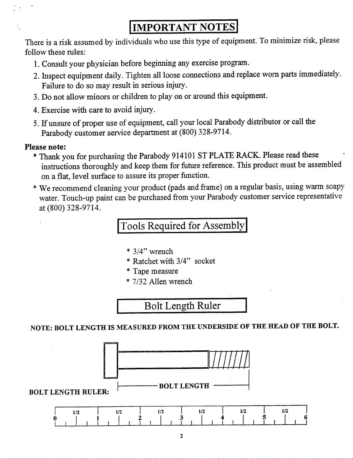
NOTE: BOLT LENGTH IS MEASURED FROM THE UNDERSIDE OF THE HEAD OF THE BOLT.
Bolt Length Ruler
’l
II!/!//!!i
BOLT LENGTH RULER:
1/2 [
BOLT LENGTH
1/2 1/2 [
I
112
3
112
I
5 6
112
Page 3

[
PARTS LIST
KEY
1
2
3
4
5
6
7
8
9
PART # DESCRIPTION
6690101 FRAME WELDMENT
6690401 1-1/2" DIA X 19" TUBE
3102502 3/8" LOCKWASHER
3102910 1/2 X 3" BOLT
3102801 1/2" LOCKNUT
3102502
3102502 1/2" FLAT WASHER
3202401 3/8 X 1" BUTTON HEAD CAP SCREW
6615503 3 X 2 X 18" TUBE
RUBBER BUMPER
QT~
1
4
4
4
4
8
4
4
2
1/2 X 3"
FIGURE 1
STEP 1: SECURELY assemble two 3 X 2 X 18" TUBES (9) to the FRAME WELDMrI’ (1) using four 1/2 X
BOLTS (4) four 1/2" FLAT WASHERS (7) and four 1/2" LOCKNUTS (5) ~s shown in FIGURE
1/2
6
Page 4

FIGURE 2
STEP 2: Insert the four 1.-1/2 DIA X 19" TUBES (2) through the side of FRAME WELDM[ENT (1) so the threaded
hole in the 19" :IqJ-BES (2) lines up with the holes in the FRAME WELDMENT (1) as shown in FIGURE
2.
STEP 3: SECURELY assemble the four 1-1/2" DIA X 19" TUBES (2) to the FRAME WF, LDMENT (1) using
four 3/8-16 X 1" BUTI’ON ~ CAP SCREWS (8) and four 3/8" LO KWAS]EIERS (3) as shown
FIGURE 2.
FIGURE 4
STEP 4: Slide eight RUBBER BUMSPERS (6) over the ends of the 1-1/2" DIA X 19" TUBES (2) and up against
the FRAME WELDMENT (1) as shown in FIGURE
1/2 [ 1/2 I I/2 I
1 [ I I I
1/2 [ 1/2 I
5
I I I ~_l I__1
4
1/2 ]
64
 Loading...