

LifeCore Fitness VST-V8, VST-V6 User's Product Manual

User’sProductManual
LifeCOREVST‐V8VariableStride Trainer
Introduction
Congratulations on your purchase of the VST-V8 Variable Stride Trainer. This product has been
designed and manufactured to meet the needs and requirements for domestic use.
By choosing the VST-V8 Variable Stride Trainer, you have made a wise decision which will improve
your health as well as your families. Being fit and healthy will improve your energy level and your quality
of life.
Cardiovascular training is vital for all ages and the VST-V8 Variable Stride Trainer provides a more
effective workout, producing better results, and will encourage you to reach your fitness goals and
maintain the body you have always wanted.
In order to make your experience with LifeCORE the best it can be, please review the enclosed user’s
manual prior to assembly and first use. Be sure to keep the instructions for reference and/or
maintenance.
We also offer a complete line of fitness equipment; please take a moment to review our other excellent
products at www.LifeCOREfitness.com. Should you have any questions, please contact us. Your
feedback and ideas about your experience with LifeCORE are also very important to us. Please write to
us at:
LifeCORE Fitness Inc.
2575 Pioneer Ave. Suite 101
Vista, CA 92081
We wish you lots of success and fun while training!
Purchaser’s Reference Information
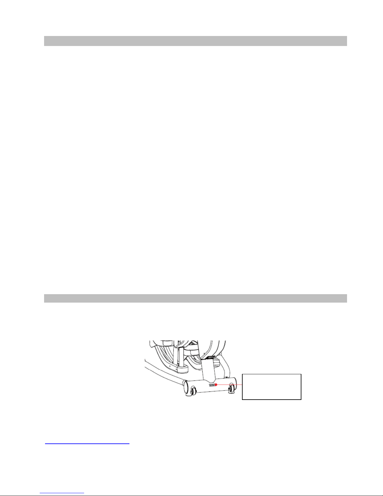
Serial Number is located on the frame
Please send in the attached warranty card and a copy of the original receipt or register online at
www.LifeCOREfitness.com
Fitness.
LifeCoreFitnessInc.
Model:VST‐V8
Serial#:010057‐001
within (10) days of purchase to register your product with LifeCORE
Page|1

Table of Contents
Introduction…………………………………………………………………………………….............
Purchaser’s Reference Information ………………………………………………………………….
Table of Contents………………………………………………………………………………………
Safety Instructions and Warnings…………………………………………………………………….
Assembly Instructions………………………………………………………………………………….
Parts List…………….. …………………………………………………………………………………
Pedal Locking Feature …..……………………………………………………………………………
How to Transport the Variable Stride Trainer ………………………………………………………
Console Operation Instructions ………………………………………………………………………
Monitoring Your Heart Rate ………………………………………………………………………….
Heart Rate Monitoring Devices ………………………………………………………………………
Care and Maintenance ……………………………………………………………………………….
Parts List & Parts Diagram……………………………………………………………………………
Warranty Card………………………………………………………………………………………….
1
1
2
3
4
5
10
10
11
19
20
21
22
26
Page|2

Safety Instructions & Warnings
The VST-V8 Variable Stride Trainer is designed and manufactured to meet or exceed all domestic and
international safety standards. However, certain precautions need to be followed when operating any
exercise equipment.
General safety instructions:
1. It is important to consult your physician before any exercise program.
2. Pregnant women should consult with their physician before beginning any exercise program.
He/she can help determine the exercise program that is the most appropriate for your age and
physical condition.
3. If you experience dizziness, nausea, chest pains or other abnormal symptoms during exercise, stop
the exercise session immediately. Consult your physician before continuing your exercise.
4. Keep children away from the equipment. Hands and feet may get caught in the pedals or other
moving parts, which could result in serious injury.
5. No more than one person should ever use the product at a time.
6. Pets should never be allowed near unit.
7. Always wear proper clothing and shoes when exercising. Drink plenty of fluids when exercising.
8. Always stretch and warm up before starting any exercise program.
9. Never operate this unit if it is damaged or broken. Contact your authorized dealer for service.
10. Place your equipment on a solid, level surface when in use.
11. Place your unit in an area with enough clearance to operate the equipment.
12. Make sure all components are fastened securely at all times.
Product safety instructions:
1. Start your exercise program gradually. Exercise only for a few minutes the first day to let your body
adjust to the new exercise.
2. Slowly increase your exercise time and intensity over the first two weeks. If you increase your
intensity too rapidly, or fail to warm up properly, you can increase the risk of injury.
3. Use of this machine with worn or weakened parts, may result in injury to the user. We strongly
suggest replacing it immediately. Use only the accessory attachments recommended by the
manufacturer.
4. Unit maximum weight limit is 300LBS
5. It is recommended the unit be plugged into a surge protector. Do not place machine in an area of
high voltage or electromagnetic fields.
6. Whenever mounting or dismounting from the exercise machine, make sure that the unit is not in
motion and use caution to prevent injury. Use the handlebars or a helper whenever additional
stability is required.
7. Make sure that all components are fastened securely including but not limited to seat, pedals,
handlebars, or any electric components.
8. Never place any open containers of any type directly on the unit, only containers with lids are
recommended to be used with the appropriate water bottle holder.
9. Keep machine clear of any obstructions, heavy machinery, and never place objects on or against
machine.
10. DANGER: Always unplug the power cord before performing maintenance.
11. Failure to follow these instructions will void the units warranty and the manufacturer or distributor
assumes no responsibility for personal injury or property damages related to the product if unit is
ever used incorrectly or for reasons other than exercise.
12. Perform proper maintenance as recommended in this manual.
Page|3
Assembly Instructions
Assembly Tips
The LifeCORE VST-V8 is made from the best materials and has been tested and received a quality
control review prior to its packaging to ensure the correct parts and proper fitting of each component.
This machine was designed to limit the amount of assembly needed by a consumer.
Before assembling your product, distinguish a proper and appropriate location for the unit where there
is easy access to an electrical outlet with a surge protector. Read the assembly instructions first before
unpacking the box in a clear work area to allow for smooth assembly. Remove all of the parts from the
packing material; however, do not discard packing material until assembly is complete. Double check
the packing materials to ensure no missing parts were left behind.
Note that some hardware may be preassembled to components in order to help with assembly; tools
have also been provided to assist with assembly. If you are missing any parts, assembly bags or need
assistance with assembly please call LifeCORE Fitness at 1-888-815-5559.
Getting Started
NOTE: Please follow all direction very carefully for proper installation.
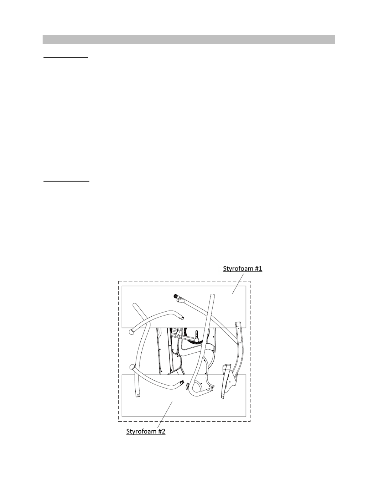
A. Lay the box down flat so that the lid is able to be lifted. Unpack the handle bars, side supporting
tubes, pedal supporting tubes and owners manual. Remove the top styrofoam pieces #1 & #2 and
finish up packing the console, central supporting tube and hardware bag, leaving the main the
frame (A) and bottom styrofoam pieces #3 & #4 inside the box until instructed to remove them.
B. Note: FOR SAFETY REASONS, DO NOT turn the pedal locking feature knob to the unlock position
until instructed to do so at the end of the assembly.
Page|4
Page|5
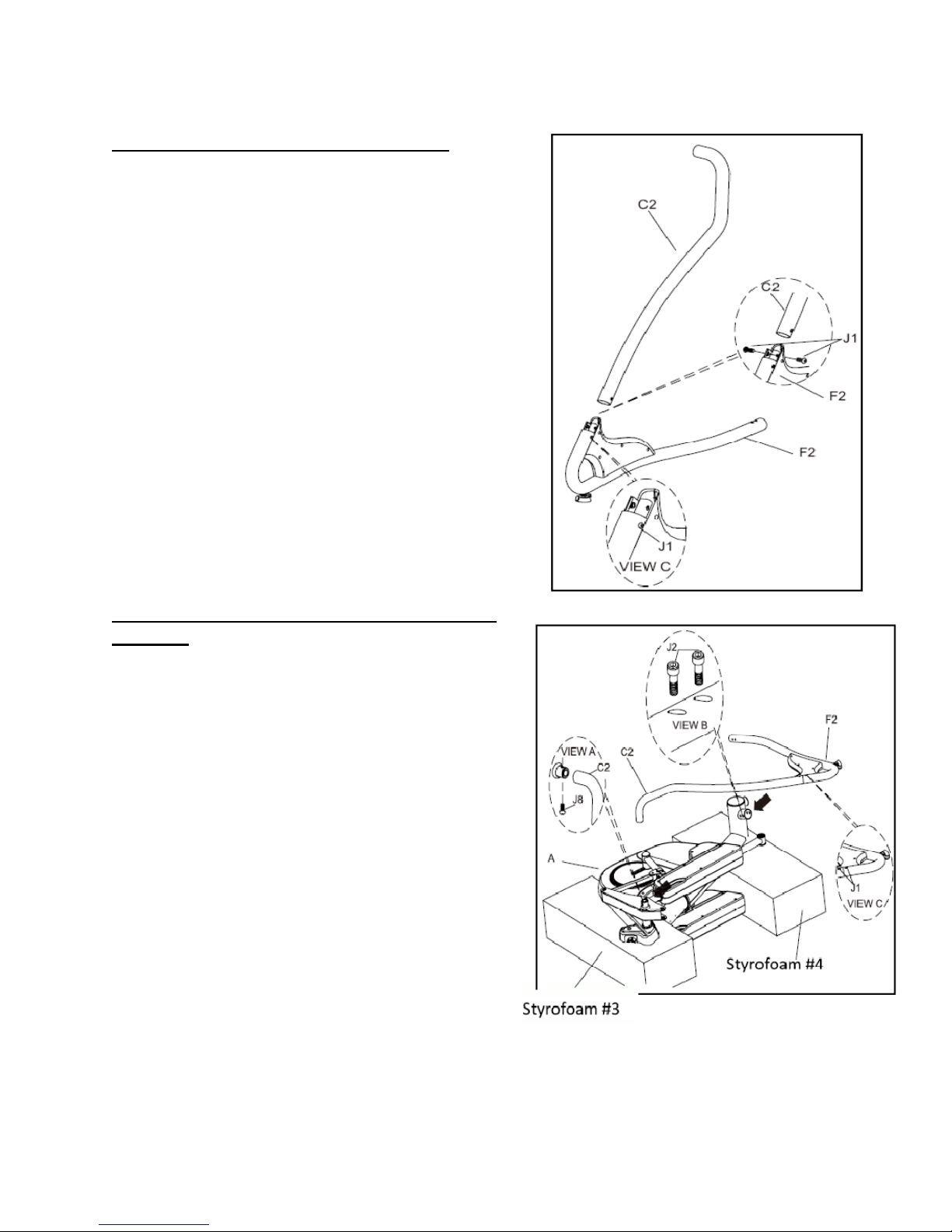
Step 1: (R) Side Supporting Tube Assembly
Note: Use page 5 as a reference to help
distinguish correct bolts for assembly, also add
the supplied blue loctite in the owner’s manual
bag to the threads of each user installed
hardware for added support.
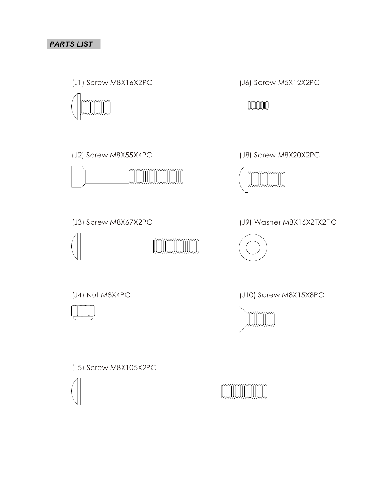
A. Locate (F2) (R) side supporting tube; remove the
two preassembled (J1) screws M8X16 from the
top of the receiver tube.
B. Assemble (C2) (R) side connecting tube onto (F2)
(R) side supporting tube, use the previously
removed (J1) screws M8X16 to join them.
Note: Only hand tighten the (J1) screws M8X16
until assembly is fully completed in step 2. Lay
arms down on the ground for easier assembly.
Adjust receiver tube to help align holes.
C. Repeat the same two steps for left side assembly.
Step 2: (R) Side Supporting Tube and Main Frame
Assembly
Tools Needed:
5mm Allen wrench
6mm Allen wrench
A. As shown in Views A & B) Assemble the right side
supporting tube assembly (C2 & F2) to the
machine. Slide the lower portion (F2) to the
bottom of main frame (A) first. Use two (J2)
screws M8x55 to join the tube to the frame.
Note: Only hand tighten the two (J2) screws
M8x55 until instructed to use the tool to finish
assembly.
B. As shown in View A) Assemble the right top
supporting tube assembly (C2 & F2) onto the
upper main frame (A). Use one (J8) screw M8x20
to join the tube to the frame.
C. Now that the right side supporting tube assembly
is complete, tighten all screws from steps 1 & 2 as
show in View A one (J8), View B two (J2) & View
C four J1 screws. Use the 5mm & 6mm Allan
wrench to fasten bolts firm.
Page|6
Step 3: (L) Side Supporting Tube Assembly and
Main Frame Assembly
Note: For SAFETY REASONS: Additional
assistance may be needed to help lift main frame
assembly to the upright position.
A. After assembling the right side supporting tube
assembly, raise the main frame (A) to the upright
position.
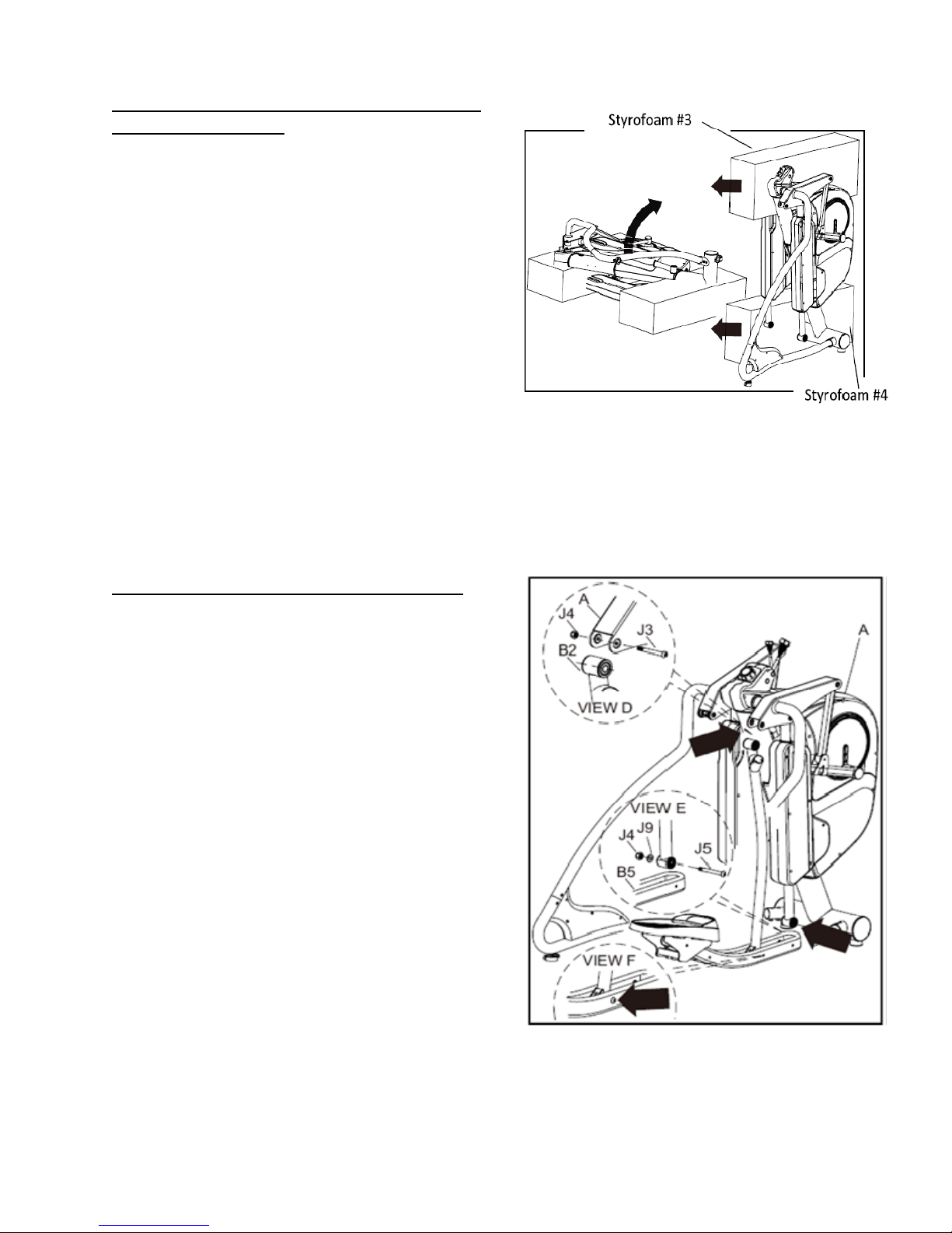
B. Remove the styrofoam pieces (#3 & #4) as show
on the diagram.
C. Assemble the left side supporting tube assembly
onto the main frame the same way as the right
side supporting tube assembly. Please refer to
steps 1 & 2 for assembly procedure.
Step 4: (R) Pedal Supporting Tube Assembly
Tools Needed:
13mm wrench
6mm Allen wrench
Note: Use page 5 as a reference to help
distinguish correct bolts for assembly. Additional
assistance may be needed.
A. As shown in View D) Connect the right pedal
supporting tube (B2) to main frame (A). Use the
tools provided to tighten (J3) bolt M8x67 and (J4)
nut M8.
B. As shown in View E) Connect and align the right
lower pedal supporting tube (B5) to the front
pedal supporting tube on the main frame (A). Use
the tools provided to tighten (J5) bolt M8x105,
(J9) washer M8x16x2T and (J4) nut M8 firm, but
DO NOT OVER Tighten.
C. As shown in View F) Tighten the preinstalled (J5)
bolt M8x105 and (J4) nut M8 firm, but DO NOT
OVER Tighten.
D. Repeat the previous same steps for the left pedal
tube assembly (B1 & B2).
Page|7
Step 5: Handlebar Assembly
Tools Needed:
5mm Allen wrench
Note: Add the supplied blue loctite in the owner’s
manual bag to the threads of the (J10) bolts for
added support.
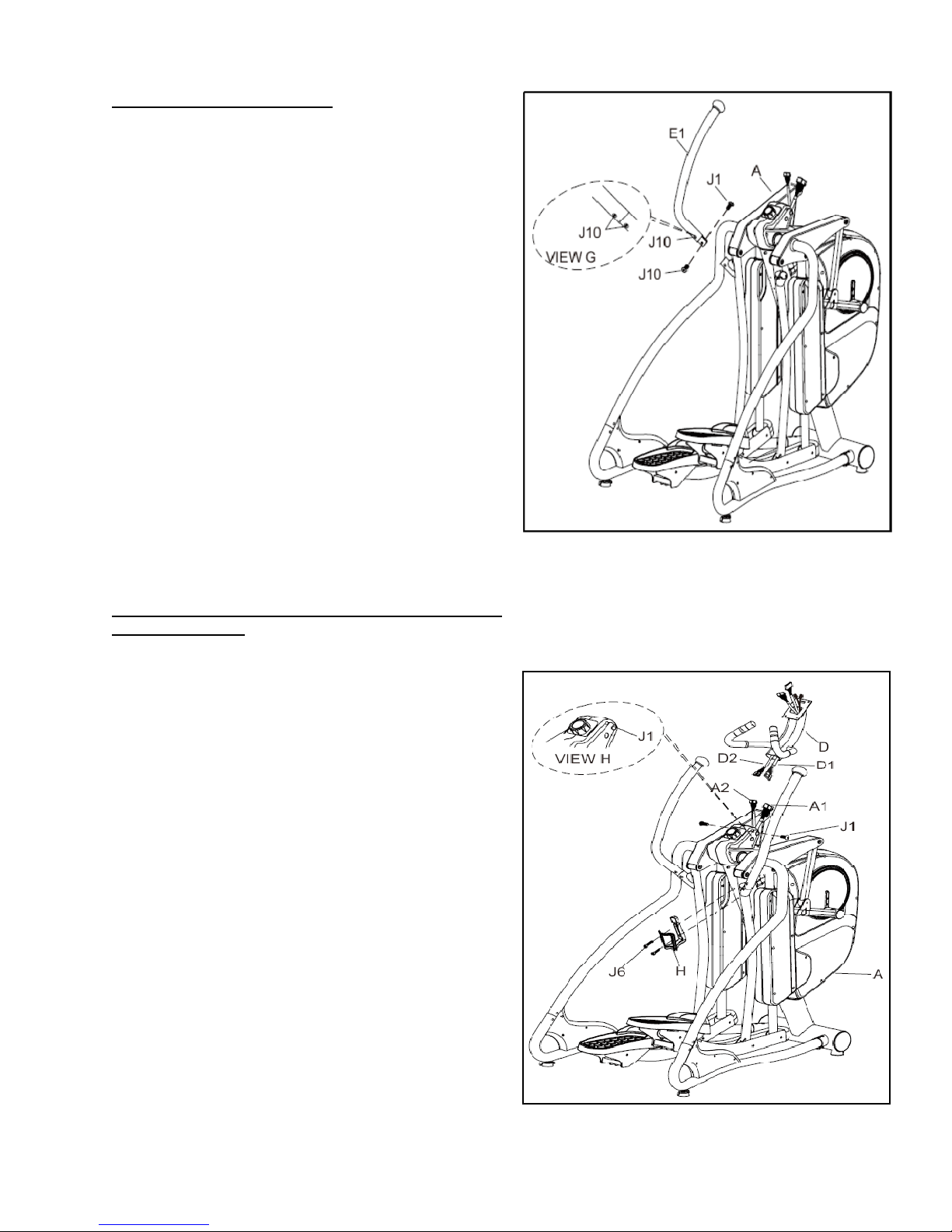
A. Only remove the two lower preinstalled (J10)
screws from the left handle bar (E1). Slightly
loosen the top (J10) bolts, but do not remove.
B. As shown in View G) Assemble the left handle bar
(E1) onto the main frame (A). Apply the supplied
blue loctite to the treads of all four (J10) bolts, and
using the 5mm Allan wrench to tighten the four
(J10) bolts firm.
Note: Make sure to tighten handle bar bolts tight
to prevent a clicking noise in the handle bars.
Wiggle the handle bars to help seed bolts in place
and then retighten.
C. Repeat the same steps for the right handlebar
(E2).
Step 6: Central Supporting Tube and Water Bottle
Holder Assembly
Tools Needed:
5mm Allen wrench
6mm Allen wrench
Note: Make sure that all wires are connected
together properly; all (J1) bolts are tight to prevent
a loose central support tube.
A. Connect wires (D1 & D2) from the central
supporting tube (D) to wires (A1 & A2) from the
main frame (A).
B. Slide the central supporting tube (D) onto the
main frame (A). Store excess wires into the tube.
If needed, loosen the preinstalled (J1) screw in
the main frame (A) to help slide central supporting
tube down or to help align holes for the (J1)
screws M8x16.
D. Apply the supplied blue loctite to the treads of
both (J1) bolts M8x16, and using the 5mm Allan
wrench tighten the four (J1) bolts M8x16 tight.
C. Use the two (J6) screws located in the water
bottle holder bag to join water bottle holder (H) to
the main frame (A).
Page|8
 Loading...