

LifeCore Fitness LifeSport LS-XT, LifeSport LS-XT Air Bike User Manual
User’s Product Manual
OM Edition 8
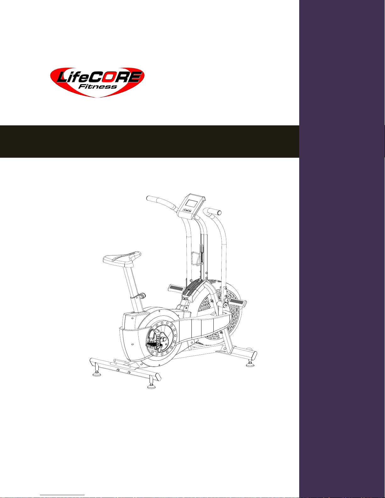
LifeSport LS-XT Air Bike
Introduction
Congratulations on your purchase of the LS-XT Air Bike. This product has been designed and
manufactured to meet the needs and requirements for domestic use.
By choosing the LS-XT Air Bike, you have made a wise decision that will improve your health. Being
fit and healthy will improve your energy level and your quality of life.
Cardiovascular training is vital for all ages and the LS-XT Air Bike provides a more effective workout,
producing better results, encourage you to reach your fitness goals and maintain the body you have
always wanted.
In order to make your experience with LifeCore the best it can be, please review the enclosed user’s
manual prior to assembly and first use. Be sure to keep the instructions for reference and/or
maintenance.
We also offer a complete line of fitness equipment; please take a moment to review our other
excellent products at www.lifecorefitness.com. Should you have any questions please contact us.
Your feedback and ideas about your experience with LifeCore are also very important to us. Write to
us at:
LifeCore Fitness Inc.
2575 Pioneer Ave. Suite 101
Vista, CA 92081
We wish you lots of success and fun while training!
Purchaser’s Reference Information
Serial Number is located on rear of the frame
Please send in the attached warranty card and a copy of the original receipt or register online
with us at www.lifecorefitness.com within (10) days of purchasing your product.
Page | 1
Introduction…………………………………………………………………………………….............
Purchaser’s Reference Information ………………………………………………………………….
Table of Contents………………………………………………………………………………………
Safety Instructions and Warnings…………………………………………………………………….
Assembly Instructions …………………………………………………………………………………
How to Adjust the Seat Height ……………………...……………………………………………….
Console Operation Instructions ………………………………………………………………………
Warm Up & Cool Down ……………………………………………………………………………….
Care and Maintenance ……………………………………………………………………………….
Exploded Diagram …………………………………………………………………………………….
Parts List ……………………………………………………………………………………………….
Warranty Card………………………………………………………………………………………….
1
1
2
3
4
7
8
9
10
11
12
14
Table of Contents
Page | 2

Safety Instructions & Warnings
The LS-XT Air Bike is designed and manufactured to meet or exceed all domestic and international
safety standards; however, certain precautions need to be followed when operating any exercise
equipment.
General safety instructions:
1. It is important to consult your physician before any exercise program.
2. Pregnant women should consult with their physician before beginning any exercise program.
He/she can help determine the exercise program that is the most appropriate for your age and
physical condition.
3. If you experience dizziness, nausea, chest pains or other abnormal symptoms during exercise,
stop the exercise session immediately. Consult your physician before continuing your exercise.
4. Keep children away from the equipment. Hands and feet may get caught in the pedals or other
moving parts, which could result in serious injury.
5. No more than one person should ever use the product at a time.
6. Pets should never be allowed near unit.
7. Always wear proper clothing and shoes when exercising. Drink plenty of fluids when exercising.
8. Always stretch and warm up before starting any exercise program.
9. Never operate this unit if it is damaged or broken. Contact your authorized dealer for service.
10. Place your equipment on a solid, level surface when in use.
11. Place your unit in an area with enough clearance to operate the equipment.
12. Make sure all components are fastened securely at all times.
Product Safety Instructions:
1. Start your exercise program gradually. Exercise only for a few minutes the first day to let your
body adjust to the new exercise.
2. Slowly increase your exercise time and intensity over the first two weeks. If you increase your
intensity too rapidly, or fail to warm up properly, you can increase the risk of injury.
3. Use of this machine with worn or weakened parts, may result in injury to the user. We strongly
suggest replacing it immediately. Use only the accessory attachments recommended by the
manufacturer.
4. Unit maximum weight limit is 300LBS
5. Do not place machine in an area of high voltage or electromagnetic fields.
6. Whenever mounting or dismounting from the exercise machine, make sure that the unit is not in
motion and use caution to prevent injury. Use the handlebars or a helper whenever additional
stability is required.
7. Make sure that all components are fastened securely including but not limited to seat, pedals,
handlebars, or any electric components.
8. Never place any open containers of any type directly on the unit, only containers with lids are
recommended to be used with the appropriate water bottle holder.
9. Keep machine clear of any obstructions, heavy machinery, and never place objects on or against
machine. Perform proper maintenance as recommended in this manual.
10. Failure to follow these instructions will void the units warranty and the manufacturer or distributor
assumes no responsibility for personal injury or property damages related to the product if unit is
ever used incorrectly or for reasons other than exercise.
11. Save this manual for future reference.
Page | 3
Assembly Instructions
The LS-XT Air Bike is made from the best materials and has been tested to receive a quality control
review prior to its packaging; ensuring the correct parts and proper fitting of each component.
Before assembling this product, distinguish a proper and appropriate location for the unit. Unpack
the box in a clear workable area to allow for smooth assembly. Remove all of the parts from the
packing material; however, do not discard packing material until assembly is complete. Double
check packing materials to ensure no missing parts were left behind.
Please note that some hardware may be preassembled to some components in order to help with
assembly. Tools have also been provided to assist with assembly. If you are missing any parts,
assembly bags or need assistance with assembly please call LifeCore Fitness at 1-888-815-5559.
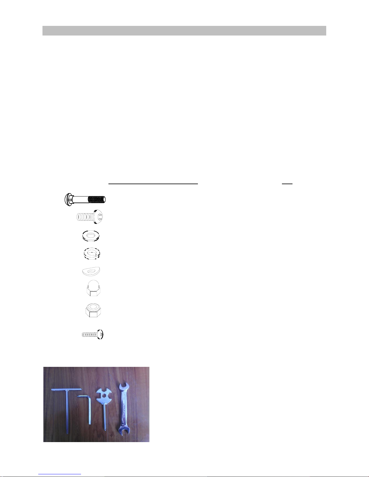
Hardware Identification List:
This list is provided to help identify the hardware used in the assembly process. Some hardware
may already be attached to the appropriate part(s).
Part Number and Description Qty
30
Carriage Bolt (M8 x 1.25 x 45mm)
“Figure 1” 4
40 Bolt, Button head (M8 x 1.25 x 20mm) “Figure 2” 4
65 Bolt, Button head (M8 x 1.25 x 45mm) “Figure 3” 4
50 Flat washer (M4) “Figure 2” 4
59 Flat washer (M8) “Figure 1” 7
16
66
Spring washer (M8) “Figure 5”
Arc washer (M8) “Figure 2 & 3” 12
67
Acorn nut (M8 x 1.25) “Figure 2 & 3” 8
48
44
31
Nylon nut (M8 x 1.25) “Figure 5” 3
Screw, Round head (M4 x 15mm) “Figure 2” 4
Screw, Round head (M5 x 10mm) “Figure 2” 2
The following tools are included for assembly:
5mm T-handle Allen wrench
3
5mm Allen wrench/screw driver
Muti-tool wrench
13 & 15mm wrench
Page | 4
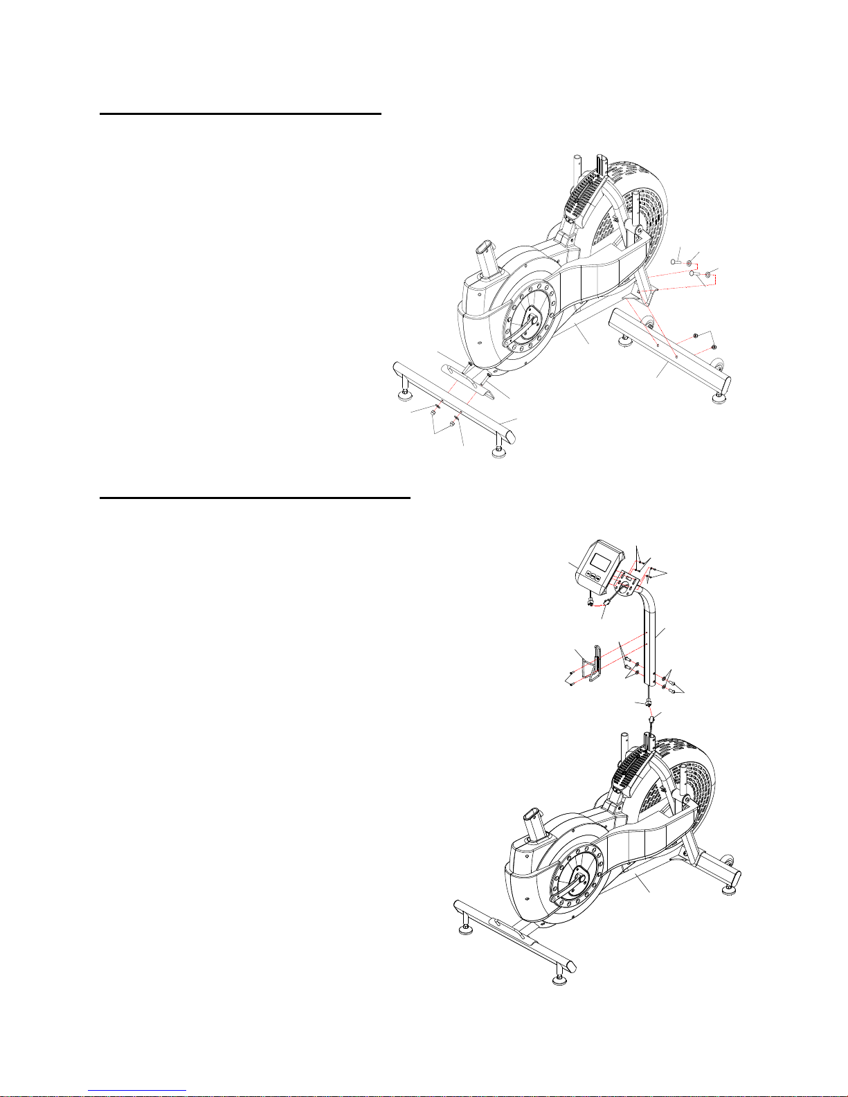
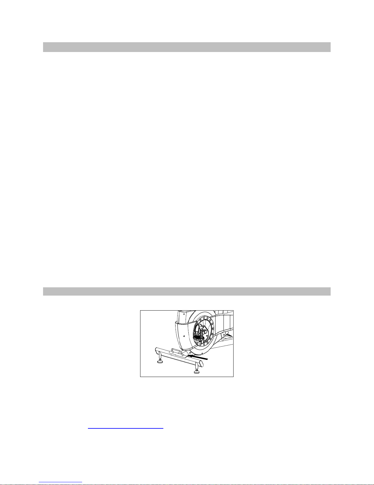
Step 1: Front & Rear Stabilizer Assembly
1) Locate the front stabilizer hardware bag
labeled Figure 1. Screw in the black
stabilizer pads to the bottom of the
stabilizer tubes #2 & #3.
2) (See Figure 1) Attach the front
stabilizer tube #(3) to the main frame
#(1). Secure it with two M8x45
carriage bolts
#(30),
#(59) and two acorn nuts
two
washers
#(67).
3) Attach the rear stabilizer tube #(2) to
the main frame part #(1). Secure it
with two M8x45
#(30), two washers #(59) and two
carriage bolts
59
acorn nuts #(67). Use the 13mm
wrench to tight all four nuts.
Step 2: Console and Console Mast Assembly
1) Locate the console mast hardware bag
labeled Figure 2.
2) (See Figure 2) Connect the lower console
wire #(75) to the main wire #(70). Note:
Ensure that all wires are properly connected
and stored inside the console mast tube. Be
careful not to pinch the wires. Carefully insert
the console mast #(5) down onto the main
frame #(1). Secure and tighten the mast with
four button head bolts #(40), and four arc
washers #(66). Use the 5mm Allen wrench to
tighten the bolts.
3) Locate the console #(26), install the two
AAA batteries into the back of the
console. Unscrew the preinstalled four
round head screws #(44) & washers
#(50). Connect the console wire #(75) to
the console #(26). Join the console to the
console mast with screws #44 & washers
#(50).
4) Locate the water bottle holder. With the
provided screw driver, remove the
preinstalled screw #(31) from the console
mast. Secure the water bottle hold to the
mast.
Figure 1
30
67
59
Figure 2
30
30
59
59
30
67
1
3
2
26
31
80
75
40
66
75
50
44
44
50
5
66
40
70
1
Page | 5
 Loading...