

Page 1
GENERAL INFORMATION ~ CHECK LIST ~ MEDICAL and SAFETY ~ WARRANTY
CARE and MAINTENANCE ~ ASSEMBLY and INSTRUCTIONS
USER GUIDE ~ SETUP INSTRUCTIONS ~ PARTS LIST ~ EXPLODED DRAWINGS
COMPUTER and SPEED TRANSMITTER INSTRUCTIONS
LUBRICATION
Page 2
The LifeCORE Sport Trainer can be used in a
home, light commercial or full commercial
setting.
The official maximum load is 400 lbs.
In the unlikely event your LifeCORE Sport
Trainer needs servicing, repairs or parts,
contact your local dealer as soon as possible.
They should be able to help you immediately
with any problem you may have. If for any
reason you are unsatisfied with the level of
service, then you can contact LifeCORE directly
by referring to the details on the back page of
this hand book.
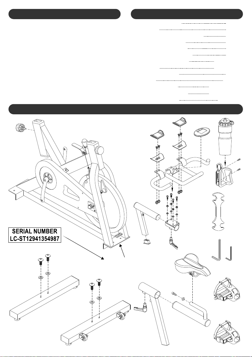
CHECK LIST
IF ANY OF THESE PARTS ARE MISSING CONTACT YOUR DEALER
TABLE OF CONTENTSGENERAL INFORMATION
General Information
Check List
Medical & Safety Information
Warranty Information
Care and Maintenance
Lubrication Instructions
Assembly Instructions
User Guide
Setup Instructions
Parts List
Exploded Drawing
Computer Instructions
LifeCORE Warranty
page 1
page 1
page 2
page 2
page 2
page 3
pages 4 ~ 6
pages 7 ~ 8
page 9
page 10
pages 11 ~ 12
pages 13 ~ 14
back page
SERIAL NUMBER
EXAMPLE
SERIAL NUMBER
LOCA TION
1
17mm
WRENCH
14mm
ALLEN
KEYS
13mm
15mm
6mm
4mm
Page 3

Read this Hand Book thoroughly to familiarize
yourself with the LifeCORE Sport Trainer before
using it.
Before beginning any exercise program, consult
your physician. He or she can help evaluate your
present fitness level and determine the exercise
program that is the most appropriate for your
age and physical condition.
If you experience any pain or tightness in your
chest, irregular heartbeat, shortness of breath,
faintness, or unusual discomfort upon
exercising, stop and consult a physician.
Adult supervision is required at all times when
children are on or near the LifeCORE Sport
Trainer. Unsupervised children should keep
away from the equipment at all times.
Keep fingers and limbs, loose clothing and hair
away from moving parts.
Before each workout on your LifeCORE Sport
Trainer we advise that a precautionary safety
check is wise. All equipment should be safety
checked for wear and damage. If you find any
damage or defective components stop using the
LifeCORE Sport Trainer immediately and
contact your dealer for help. Keep the
equipment out of use until repaired by a certified
technician.
To avoid injury, care should be taken when
getting on or off your LifeCORE Sport Trainer.
Wear comfortable, lightweight, well ventilated
clothing to help sweat evaporate. Make sure
your shoes fit you properly and provide external
and lateral stability support to prevent ankle and
knee injuries. Wear cross
training, walking, running or cycling shoes
It's very important not to become dehydrated.
Your body needs water lost during exercise.
Don't forget to warm-up and cool-down.
Limbering up "cold" muscles and cooling down
after exercise are important injury-prevention
measures.
WARNING: If you have not warmed up prior to
mounting your LifeCORE Sport Trainer, to avoid
injury we suggest you pedal slowly for at least
five minutes before beginning your exercise
program.
sports training,
.
WARRANTY
It is important to keep your purchase receipt !
You may be asked to produce it to authenticate
your warranty.
The warranty is on the back page of this hand
book.
Do not attempt to modify or alter your LifeCORE
Sport Trainer as it will be considered tampering
and will invalidate your warranty.
CARE AND MAINTENANCEMEDICAL & SAFETY
Your LifeCORE Sport Trainer is made of the highest
quality materials. However it is still important that
you take care of your LifeCORE Sport Trainer on a
regular basis.
Your LifeCORE Sport Trainer is for indoor use only
and should not be used or stored in damp areas.
Wipe all perspiration from your LifeCORE Sport
Trainer after each use.
For safety, inspect your on a
regular basis. When used in a light commercial
environment safety check and clean every day.
When used in a domestic environment safety check
and clean before use.
LifeCORE Sport Trainer
MAINTENANCE GUIDE
FELT PADS [part#109]
These parts will wear out and should be checked
regularly. If they need replacing then contact your
dealer.
RESISTANCE SYSTEM & EMERGENCY BRAKE
ASSEMBLY [part#013,014,18,204,205]
The resistance system and emergency brake
assembly has a lot of moving parts and should be
checked regularly for wear-and-tear. If any parts
need replacing then contact your dealer.
ALL CONSUMER ASSEMBLED PARTS
Refer to the assemble instructions and re-tighten all
components referred to in every assembly step
regularly to ensure that they remain tight at all times.
PEDALS [part#202,203]
These parts are assembled by the consumer so we
can not guarantee that they where assembled
correctly. To avoid injury we suggest before starting
your workout on the LifeCORE Sport Trainer that
you visually inspect the both pedals to ensure they
are securely attached to the pedal cranks according
to the assembly instructions.
All FASTENERS [Nuts, Bolts, and Screws]
Due to vibration, over time some of the fasteners
may become loose. We strongly suggest the owner
periodically check all visible fasteners at least once
a year to ensure that they remain tight.
BELT TENSION [part#102,407]
The BELT [102] only needs tensioning if belt slip
occurs whilst exercising. The belt can be tensioned
by loosening 2 x NUTS [306]. Then adjust 2 x BOLT
[407] evenly to ensure the FLYWHEEL [206]
remains central to the FELT PAD [109]. Then retighten the same 2 x NUTS [306].
NOTE: Over tensioning the belt will destroy the belt.
Make small adjustments only.
WARNING: Do not apply oil to any moving parts as
this will wash the grease away damaging your
LifeCORE Sport Trainer.
WARNING:
recommended by the manufacturer. Do not attempt
to modify or alter your as
injury may result.
Use only the accessory attachments
LifeCORE Sport Trainer
2
Page 4
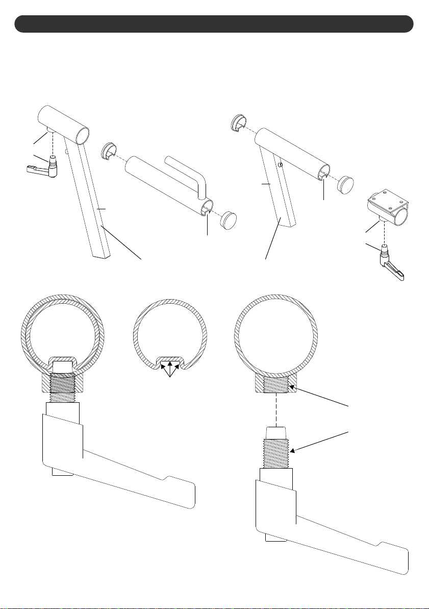
LUBRICATION INSTRUCTIONS
We strongly suggest that you follow these optional lubrication instructions to improve the ease of
making seat and handlebar adjustments and the stability of the seat and handlebar when locked.
During the assembly process lubricate the appropriate parts either with the OIL or GREASE provided
as illustrated in the diagrams below.
After assembly is complete we suggest you keep all LITERATURE for future reference and the
TOOLS + OIL + GREASE provided for maintenance.
GREASE
OIL
OIL
GREASE
SMEAR A THIN FILM OF OIL ON BOTH TUBES
SMEAR A THIN FILM OF
GREASE ALONG THE ENTIRE
"U"-TRACK ON BOTH TUBES
GREASE
GREASE
GREASE THE THREADS OF
BOTH NUTS AND HANDLES
3
Page 5
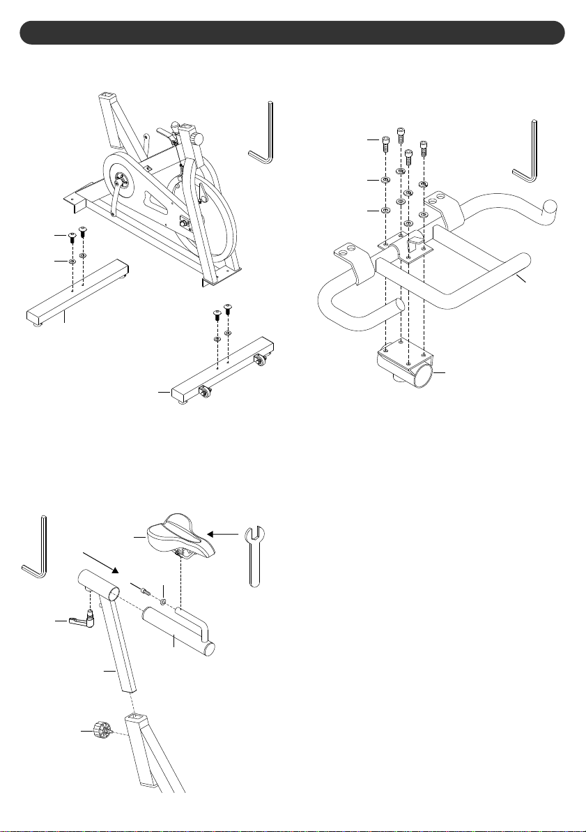
ASSEMBLY INSTRUCTIONS
STEP 1
Secure both STABILIZER [002,003] with 4x
BOLT [401] + WASHER [500] and tighten firmly.
6mm
ALLEN
KEY
401
500
003
002
Secure HANDLEBAR [009] to HANDLEBAR
STEP 3
SLIDER [008] with 4 x BOLT [404] + WASHER
[503 & 504] and tighten firmly.
404
503
504
008
6mm
ALLEN
KEY
009
a)
STEP 2
Assemble SEAT POST [011] and secure with
KNOB [105].
b)
Assemble SEAT SLIDER [012] and secure
with HANDLE [106]. Tighten firmly.
Assemble SEAT [900] and secure with
c)
SPACER [122] and BOLT [402].
6mm
ALLEN
KEY
106
105
011
900
402
122
14mm
WRENCH
012
4
Page 6

ASSEMBLY INSTRUCTIONS
a)
Assemble the COMFORT PADS [121] on
HANDLEBAR [009] by securing 2 x
COMFORT PAD PLATE with VELCRO [010]
to HANDLEBAR [009] with 4 x BOLT [405] +
NUT [307].
b)
Assemble the COMFORT PADS [121] on 2 x
COMFORT P AD PLA TE with VELCRO [010].
NOTE: The COMFORT PADS [121] are held in
place with velcro, which means they can be
easily removed and repositioned if desired.
STEP 4
121
a)
STEP 5
Insert HANDLEBAR POST [007] into MAIN
FRAME [001] and secure by tightening
KNOB [105].
b)
Slide HANDLEBAR [009] onto HANDLEBAR
POST [007] and secure by tightening
HANDLE [106].
c)
Slide COMPUTER [800] onto HANDLEBAR [009].
007
800
405
307
13mm
WRENCH
010
009
009
105
001
106
STEP 6
a)
Assemble PEDALS [202,203]. The right
pedal (marked R) is assembled in a clockwise
direction. The left pedal (marked L) is
assembled in a counter-clockwise direction.
Tighten well but avoid excessive force.
Recommended torque is 34 Nm (340 kgf/cm)
NOTE: The LEFT PEDAL [202] is reverse-threaded.
b)
Secure WATER BOTTLE HOLDER [115] with
2 x BOLT 406.
15mm
WRENCH
202
Counterclockwise
4mm
ALLEN
KEY
5
Clockwise
203
406
115
Page 7

OPTIONAL ASSEMBLY INSTRUCTIONS
The LifeCORE Sport Trainer comes with this optional handlebar post STABILITY PLUG [108].
This STABILITY PLUG [108] can not be assembled by the manufacturer as it would increase the
carton size and reduce the container loading which inturn would increase the cost. So in order to keep
costs down to our valued customers and still provide the STABILITY PLUG [108] these optional
assembly instructions where devised.
The STABILITY PLUG [108] will help stabilize the HANDLEBAR POST [007]. If you feel that the
HANDLEBAR POST [007] is already stable enough then you need not bother with this optional
assembly. However if when the HANDLEBAR POST [007] is set at maximum and you can feel the
HANDLEBAR POST [007] wobble slightly then this optional assembly will eliminate the wobble.
a)
With the LifeCORE Sport Trainer fully assembled, lower the HANDLEBAR POST [007] to level 1,
the lowest level and do not tighten KNOB [105].
b)
Insert the STABILITY PLUG [108] with the tabs pointing to the rear of the machine as illustrated in
the diagram below, into the bottom of the HANDLEBAR POST [007].
c)
Ensure the STABILITY PLUG [108] is completely inserted into the HANDLEBAR POST [007] as
007
shown in the picture below.
105
108
TAB
STABILITY PLUG [108]
6
Page 8

USER GUIDE
There are 2 x HANDLES [106] on your LifeCORE Sport Trainer that adjust the handlebar and seat horizontally.
To operate the handles rotate clockwise to lock and counterclockwise to unlock. The spring loaded locking
system allows you to free rotate the handle without locking or unlocking. To use the spring loaded locking
system simply pull the handle, then rotate. This is necessary when the handle is too close and cannot be rotated
HANDLES
SPRING LOADED
LOCKING SYSTEM
Free
Rotate
106
Unlock
Counterclockwise
Lock
Clockwise
SNAP PIN KNOB
There are 2 x SNAP PIN KNOB [105] on your LifeCORE Sport Trainer that adjust the handlebar and
seat vertically. The seat post has 11 x vertical settings, and the handlebar post has 5 x vertical
settings. To operate the snap pin knobs turn counterclockwise to loosen the knob then pull to release
the snap pin to adjust the seat post or handlebar post up or down. After vertical adjustment is complete
ensure that the snap pin snap s into the adjustment holes, then turn clockwise and tighten firmly
Clockwise
Tighten
105
Counterclockwise
Loosen
RESISTANCE KNOB
The resistance system has been designed with micro
resistance which allows you to adjust the resistance
in minute fractions. Rotate the RESISTANCE KNOB
[118] clockwise for more resistance and
counterclockwise for less resistance.
118
Pushing down on the EMERGENCY BRAKE
EMERGENCY BRAKE
LEVER [014] will instantly stop the flywheel and
pedals. This is extremely important to avoid injury
as the flywheel and pedals are permanently linked.
Push Down
Pull to Release
Clockwise = More Resistance
Counterclockwise = Less Resistance
014
7
Page 9

USER GUIDE
The LifeCORE Sport Trainer pedals have been specifically designed for use on stationary fitness equipment.
These pedals are designed to be used with the supplied VP-C01 cleats. It is recommended that you
consult a bicycle dealer for assistance and refer to your shoe manufacturers instructions.
When fixing the cleat the lateral center line should be under the center of the ball of the feet. Adjust
forwards and backwards via the slots in the shoe sole. Adjust laterally via play between the cleat
washer and cleat. Tighten cleats very firmly. As it may take time to find your optimum cleat set-up the
cleat position can be fine-tuned according to personal preference after trial use.
All standard toe clips can be attached to the pedals. Use the fixing hardware and installation instructions
supplied with the toe clips and ensure the attachment screws are firmly tightened before use.
Engage cleated shoes in pedals by placing cleat between bindings while pushing down.
Disengage by twisting heel outwards away from your IC-70 Exercycle.
Binding tension is adjustable and should be set so that the cleat and shoe does not disengage while
exercising. Use an Allen key to turn tension adjusting screws, clockwise to increase binding tension,
anti-clockwise to reduce it.
Use the reverse side to the clip-in side when using sports training,
. The regular side can be used with or without toe clips.
shoes
PEDAL INSTRUCTIONS
Attaching Cleats to Shoes
Toe Clips
Using the Pedals
cross training, walking, running
The COMFORT PADS [121] are held in place with velcro for easy removal for washing.
NOTE: Wash by hand only. Do not machine wash.
FEET LEVELING ADJUSTERS
COMFORT PADS
Adjust one of 4 x FEET LEVELING ADJUSTERS [120] to ensure your LifeCORE S port T rainer is stable and level.
Rotate all 4 x WING NUT [303] counterclockwise to lock the FEET LEVELING ADJUSTERS [120] in place.
303
Clockwise
Down
Counterclockwise
Up
120
8
Page 10

SETUP INSTRUCTIONS
The LifeCORE Sport Trainer has both vertical and horizontal adjustment for the seat and handlebar
as it is important to correctly adjust the seat and handlebar to fit your body type. These adjustment
systems have been designed to ensure a quick and easy custom fit.
If your legs are too straight or your feet cannot
reach the pedals then you will need to lower the
seat. If your legs are bent too much you will need
to raise the seat.
011
105
a)
To adjust the SEAT POST [011] rotate the
KNOB [105] counterclockwise and pull.
Slide the SEAT POST [011] up or down to
b)
suit your body type.
c)
Lock the SEAT POST [011] by rotating the
KNOB [105] clockwise.
d)
Note the seat post position for future
reference.
HORIZONTAL SEAT
The horizontal seat adjustment is designed for
minute seat adjustment for a custom fit workout.
If your legs are too vertical you will need to
adjust the seat forward. If your legs are bent too
much you will need to adjust the seat aft.
VERTICAL SEAT POST
The vertical handlebar adjustment is designed
specifically for the crouched position. Move the
handlebar to suit your body type.
a)
b)
c)
d)
The horizontal handlebar adjustment is
designed for minute handlebar adjustment for a
custom fit workout.
VERTICAL HANDLEBAR
007
106
To adjust the HANDLEBAR POST [007]
rotate the KNOB [106] counterclockwise and
pull.
Slide the HANDLEBAR POST [007] up or
down to suit your preference.
Lock the HANDLEBAR POST [007] by
rotating the KNOB [106] clockwise.
Note the handlebar post position for future
HORIZONTAL HANDLEBAR
009
900
106
a)
To adjust the SEAT [900] forward or aft,
rotate the HANDLE [106] clockwise.
b)
Slide the SEAT [900] forward or aft to suit
your body type.
c)
Lock the SEAT [900] by rotating the HANDLE
[106] counterclockwise.
d)
Note the seat position for future reference.
a)
To adjust the HANDLEBAR [009] forward or
aft, rotate the HANDLE [106] clockwise.
b)
Slide the HANDLEBAR [009] forward or aft to
your preference.
Lock the HANDLEBAR [009] by rotating the
c)
HANDLE [106] counterclockwise.
Note the handlebar position for future
d)
reference.
9
106
Page 11

PART S LIST
PART
DESCRIPTION Q’TY
No.
001
MAIN FRAME
002
STABILIZER - FRONT
003
STABILIZER - REAR
ADJUSTMENT BLOCK
004
FLYWHEEL SHAFT
005
SPACER
006
HANDLEBAR POST
007
HANDLEBAR SLIDER
008
HANDLEBAR
009
COMFORT PAD PLATE with VELCRO
010
SEAT POST
011
SEAT SLIDER
012
RESISTANCE WING NUT
013
EMERGENCY BRAKE LEVER
014
PEDAL CRANK SHAFT
015
CHAIN GUARD - COVER PLATE
016
CHAIN GUARD - INNER
100
K5 BELT PULLEY
101
K5 BELT
102
CHAIN GUARD - OUTER
103
PEDAL CRANK PLUG
104
KNOB
105
HANDLE
106
PLUG
107
STABILITY PLUG
108
FELT PAD
109
NUT COVER
110
NUT COVER
111
PLUG
112
SLIDER PLUG with PLATE
113
PLUG
114
WATER BOTTLE HOLDER
115
WATER BOTTLE
116
WHEEL
117
KNOB
118
EMERGENCY BRAKE LEVER COVER
119
FEET LEVELING ADJUSTERS
120
COMFORT PAD
121
SPACER
122
PART
DESCRIPTION Q’TY
No.
1
1
1
2
1
2
1
1
1
2
1
1
1
1
1
1
1
1
1
1
2
2
2
4
1
2
2
4
4
3
1
1
1
2
1
1
4
2
1
200
CRANK - LEFT
201
CRANK - RIGHT
202
PEDAL - LEFT
PEDAL - RIGHT
203
RESISTANCE CALIPERS
204
RESISTANCE CABLES
205
FLYWHEEL
206
NUT
300
NUT
301
NUT
302
NUT
303
NUT
304
NUT
305
NUT
306
NUT
307
BOLT
400
BOLT
401
BOLT
402
BOLT
403
BOLT
404
BOLT
405
BOLT
406
BOLT
407
BOLT
408
BOLT
409
BOLT
410
WASHER
500
WASHER
501
WASHER
502
WASHER
503
WASHER
504
SCREW
600
SCREW
601
COMPUTER
800
SPEED TRANSMITTER
801
MAGNET
802
SEAT
900
BEARING 6004
901
BEARING 6204
901
1
1
1
1
1
2
1
1
2
4
2
4
1
4
4
3
4
1
2
4
4
2
2
4
4
1
4
1
2
4
4
6
4
1
1
1
1
2
2
10
Page 12

9 01
301
103
102
015
304
101
409
201
203
600
601
600
600
600
113
118
113
500
401
112
112
303
120
003
900
107
012
011
114
403
106
122
402
107
901
300
301
104
200
202
105
408
004
407
801
112
500
401
117
111
111
302
400
112
120
303
001
100
016
406
116
115
302
501
013
105
113
302
119
014
400
104
002
601
600
601
EXPLODED VIEW
11
Page 13

0 06
502
110
006
005
306
306
902
902
306
502
110
205
305
410
109
204
802
206
306
106
108
800
009
121
405
307
010
504
503
404
008
403
107
007
107
EXPLODED VIEW
12
Page 14

LCD DISPLAY
Liquid Crystal Display
DISTANCE DISPLAY
kilometers (Km) or miles (Mile)
SPEED DISPLAY
kilometers per hour(KPH)
miles per hour(MPH)
OR
HEART RATE DISPLAY
Your heart rate/pulse is displayed in
beats per minute (BPM).
NOTE: If the letter"P" is displayed then
the computer is not receiving a pulse
NOTE: SPEED and HEART RATE
share the same display.
Press the Key to alternate the
display which will also change the
CALORIES / RPM Display
signal.
t
as they are linked.
COMPUTER INSTRUCTIONS
TIME DISPLAY
hours, minutes and seconds
CALORIES DISPLAY
Measured in kilocalories (K/CAL).
Also known as large Calories
and food Calories.
RPM / CADENCE DISPLAY
revolutions per minute (RPM)
NOTE: CALORIES and RPM share the
Press the Key to alternate the
display which will also change the
SPEED / HEART RATE Display
same display.
t
as they are linked.
LOW BATTERY DISPLAY
The low battery display will flash when
the batteries need replacing.
t
KEY
two functions
1 - Decrease Target Value
During target value selection, press the
t
Key to decrease your target value.
2 - Alternate both Displays
During and after your workout, press
t
the Key to alternate both displays
SPEED and HEART RATE Display
CALORIES and RPM Display
between:
PLUS
as they are linked.
SELECT KEY
two functions
1 - Activate Target Value Selection
Before your workout, press the
SELECT Key once to impute your time
Press the SELECT Key twice to
impute your distance target value.
Press and hold the SELECT Key for
three seconds to reset the computer.
NOTE: You will loose all data recorded
target value
OR
2 - Reset the Computer
by the computer.
FAST TRACK
Key or the KeyPress and hold either the t u
to fast track during target value selection.
13 13
MAXIMUM & AVERAGE
DISPLAY
During your workout press the Key
to alternate between the following:
MAX SPEED / CALORIES
AVG SPEED / CALORIES
SPEED / CALORIES
MAX HEART RATE / MAX RPM
AVG HEART RATE / AVG RPM
HEART RATE / RPM
NOTE: The SPEED / HEART RATE
and CALORIES / RPM displays are
After your workout the computer will
automatically display your total and
maximum and average values for
approximately 75 seconds.
1 - Increase Target Value
During target value selection, press
u
the Key to increase your target
2 - Alternate both Displays
During your workout, press the Key
to alternate both displays to show the
MAXIMUM, AVERAGE and CURRENT
OR
linked.
u
KEY
two functions
value.
display data.
u
u
Page 15

COMPUTER INSTRUCTIONS
SPEED TRANSMITTER
Note that there is no wire connected to the computer. This allows for more
freedom with handlebar adjustment and improves the appearance of the bike.
However this also means that the speed signal is sent to the computer via a radio
wave by the speed transmitter which runs on a battery. This battery needs
replacing after approximately six months of home use.
The speed transmitter must be pointing towards the computer as shown in the
diagram in order for the computer to receive the speed signal.
The speed transmitter has a red LED that will flash once every revolution of the
flywheel. If the red LED does not flash then replace the battery. If that fails to
correct the problem then contact your dealer for a replacement.
COMPUTER
BATTERIES
BATTERY INSTALLATION ~ SPEED TRANSMITTER: The speed transmitter is
visibly located at the front of the bike. Remove the battery cover and install one
piece of CR2032 3V battery. Replace the battery cover and insure it is tightly closed.
BATTERY INSTALLATION ~ COMPUTER: Remove the battery cover at the rear of the computer and install
two pieces of SIZE"AA" 1.5V batteries. Insure the batteries are correctly positioned and the battery springs
are in proper contact with batteries. Replace the battery cover and insure it is tightly closed.
BATTERY LIFE: Battery life is approximately six months of home use, depending on frequency of use and the
quality of the batteries. To ensure long battery life we suggest using alkaline or lithium batteries.
COMPUTER LOW BATTERY Display: The low battery display will flash when the computer batteries
need replacing.
SPEED TRANSMITTER LOW BATTERY: When the computer speed display is irregular or not
responding then it is time to replace the speed transmitter battery.
TRANSMITTER
Auto Power Up & Power Down
AUTO POWER UP: The computer will automatically power up when the bike is in use. Note, there is a brief
delay. The computer will also power up when any keys are pressed.
AUTO POWER DOWN: The computer will automatically power down when the bike is not in use after
approximately 75 seconds.
()
TARGET VALUES
TIME or DISTANCE target values are optional. You can only choose one target value, either time or distance. If
you do not select any of these optional target values then the computer will count from zero upwards. If you
select one of these optional target values then the computer will countdown from your selection. The computer
will stop and sound an alarm once the target value has been achieved. Press the SELECT Key to stop the alarm.
TIME: 1:00~99:55:00 minutes (in 5 minute steps).
DISTANCE: 1.0~999.0 kilometers or miles (in 1.0 steps).
TIME or DISTANCE
HEART RATE RECEIVER and CHEST BANDS
The computer has a built in chest band receiver that uses the international standard 5 kHz bandwidth. Your heart
rate will only register on the computer if you are wearing a compatible chest band. If you are unsure that your
existing chest band is compatible then contact your dealer for verification.
TROUBLE SHOOTING SOLUTIONS
If for any reason you are having trouble with your computer or speed transmitter then try the following suggestions:
1) SPEED TRANSMITTER FUNCTION: With someone pedaling the bike, check to ensure that the speed
transmitters red LED is flashing as shown in the diagram above. If not flashing then replace the battery.
2) SPEED TRANSMITTER DIRECTION: Check to ensure that the speed transmitter is pointing towards the
computer as shown in the diagram above.
3) COMPUTER RESET: Press and hold the SELECT Key for three seconds.
4) COMPUTER REBOOT: Disconnect the power for approximately 15 seconds by removing the batteries.
Wait 15 seconds, then reinstall batteries.
5) REPLACE BATTERIES: Discard the old computer and speed transmitter batteries and replace them with
fresh new alkaline or lithium batteries.
RED
LED
SPEED
14
Page 16

FULL COMMERCIAL: 1yr parts, 90 days on wearable items.
LIGHT COMMERCIAL: 2yrs parts, 1yr labor, 90 days on wearable items.
RESIDENTIAL: 5yrs parts, 1yr labor, 90 days on wearable items.
WEARABLE ITEMS: Seat, Pedals, Handlebar Grip, Comfort Pads, Felt Pads, Handles, Knobs.
LIFETIME WARRANTY on FRAME
This warranty is valid only in accordance with the following conditions:
1) This warranty applies to the Sport Trainer products only while the product remains
in the possession of the original purchaser and proof of purchase is demonstrated.
2) This warranty excludes misuse, abuse, alteration, improper service, or non Sport
Trainer product modifications.
3) This warranty is in lieu of all warranties, expressed or implied, and/or all other
obligations or liabilities on our part and we neither assume nor authorize any
person to assume for us any other obligation or liability in connection with the sale
of the Sport Trainer. Under no circumstances shall we be liable by virtue of this
warranty or otherwise for damage to any person or property whatsoever for any
special, indirect, incidental, secondary or consequential damage of any nature
whatsoever arising out of the use or inability to use the Sport Trainer.
WARRANTY REGISTRATION
Go online and visit our company website at www.lifecorefitness.com
Click “Product Registration” and fill-in all the details, then click send.
The Serial Number is located on your Sport Trainer.
See page 1 for the location of the Serial Number.
LIFECORE FITNESS
242 Bingham Rd. #101
San Marcos, CA 92069
TEL: (760) 471-7442
FAX: (760) 471-1324
EMAIL: Service@LifeCoreFitness.com
TOLL FREE: (888) 815-5559
 Loading...