

LifeCore Fitness LC?R100 Rower User's Product Manual
User’sProductManual
LifeCoreLC‐R100Rower
Introduction
Congratulations on your purchase of the LC-R100 Rower. This product has been designed and
manufactured to meet the needs and requirements for domestic and light commercial use.
By choosing the R100 rower, you have made a wise decision which will improve your health as well
as your families. Being fit and healthy will improve your energy level and your quality of life.
Cardiovascular training is vital for all ages and the R100 rower provides a more effective workout,
producing better results, and will encourage you to reach your fitness goals and maintain the body
you have always wanted.
In order to make your experience with LifeCORE the best it can be, please review the enclosed
user’s manual prior to assembly and first use. Be sure to keep the instructions for reference and/or
maintenance.
We also offer a complete line of fitness equipment; please take a moment to review our other
excellent products at www.LifeCOREfitness.com. Should you have any questions, please contact us.
Your feedback and ideas about your experience with LifeCORE are also very important to us.
Please write to us at:
LifeCORE Fitness Inc.
2575 Pioneer Ave. Suite 101
Vista, CA 92081
We wish you lots of success and fun while training!
Purchaser’s Reference Information
Please send in the attached warranty card and a copy of the original receipt or register online
at www.lifecorefitness.com
LifeCore Fitness.
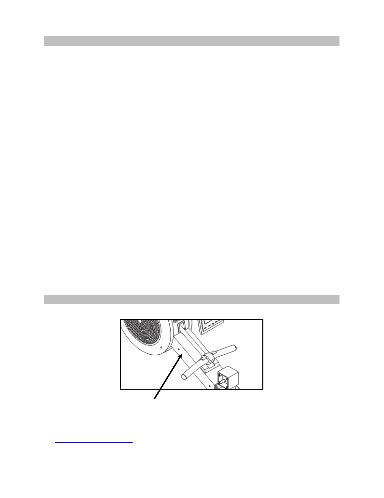
Serial Number is located on the frame
within (10) days of purchase to register your product with
Page1

Table of Contents
Introduction…………………………………………………………………………………….............
Purchaser’s Reference Information ………………………………………………………………….
Table of Contents………………………………………………………………………………………
Safety Instructions and Warnings…………………………………………………………………….
Assembly Instructions………………………………………………………………………………….
Setting Up Your Rower ……………………………………………………………………………….
Correct Rowing Guide ………………………………………………………………………………...
Console Operation Instructions ………………………………………………………………………
Calculating Target Heart Rate ……………………………………………………………………….
Heart Rate Monitoring Devices……………………………………………………………………….
Care and Maintenance ……………………………………………………………………………….
Trouble Shooting ………………………………………………………………………………………
Parts List and Parts Diagram...……………………………………………………………………….
Warranty Card………………………………………………………………………………………….
1
1
2
3
4
7
12
15
23
24
25
26
27
29
Page2

Safety Instructions & Warnings
The LC-R100 Rower is designed and manufactured to meet or exceed all domestic and international
safety standards; however, certain precautions need to be followed when operating any exercise
equipment.
General Safety Instructions:
1. It is important to consult your physician before beginning any exercise program.
2. Pregnant women should consult with their physician before beginning any exercise program.
He/she can help determine the exercise program that is the most appropriate for your age and
physical condition.
3. If you experience dizziness, nausea, chest pains or other abnormal symptoms during exercise,
stop the exercise session immediately. Consult your physician before continuing your exercise.
4. Keep children away from the equipment. Hands and feet may get caught in the pedals or other
moving parts, which could result in serious injury.
5. No more than one person should ever use the product at a time.
6. Pets should never be allowed near unit.
7. Always wear proper clothing and shoes when exercising. Drink plenty of fluids when exercising.
8. Always stretch and warm up before starting any exercise program.
9. Never operate this unit if it is damaged or broken. Contact your authorized dealer for service.
10. Place your equipment on a solid, level surface when in use.
11. Place your unit in an area with enough clearance to operate the equipment.
12. Make sure all components are fastened securely at all times.
Product Safety Instructions:
1. Start your exercise program gradually. Exercise only for a few minutes the first day to let your
body adjust to the new exercise.
2. Slowly increase your exercise time and intensity over the first two weeks. If you increase your
intensity too rapidly, or fail to warm up properly, you can increase the risk of injury.
3. Use of this machine with worn or weakened parts, may result in injury to the user. We strongly
suggest replacing it immediately. Use only the accessory attachments recommended by the
manufacturer.
4. Unit maximum weight limit is 600LBS
5. It is recommended the unit be plugged into a surge protector. Do not place machine in an area of
high voltage or electromagnetic fields.
6. Make sure that all components are fastened securely including but not limited to seat, pedals,
handlebars, or any electric components.
7. Never place any open containers of any type directly on the unit.
8. Keep machine clear of any obstructions, heavy machinery, and never place objects on or against
machine.
9. DANGER: Always unplug the power cord before performing maintenance.
10. Failure to follow these instructions will void the units warranty and the manufacturer or distributor
assumes no responsibility for personal injury or property damages related to the product if unit is
ever used incorrectly or for reasons other than exercise.
11. Perform proper maintenance as recommended in this manual.
Page3
Assembly Instructions
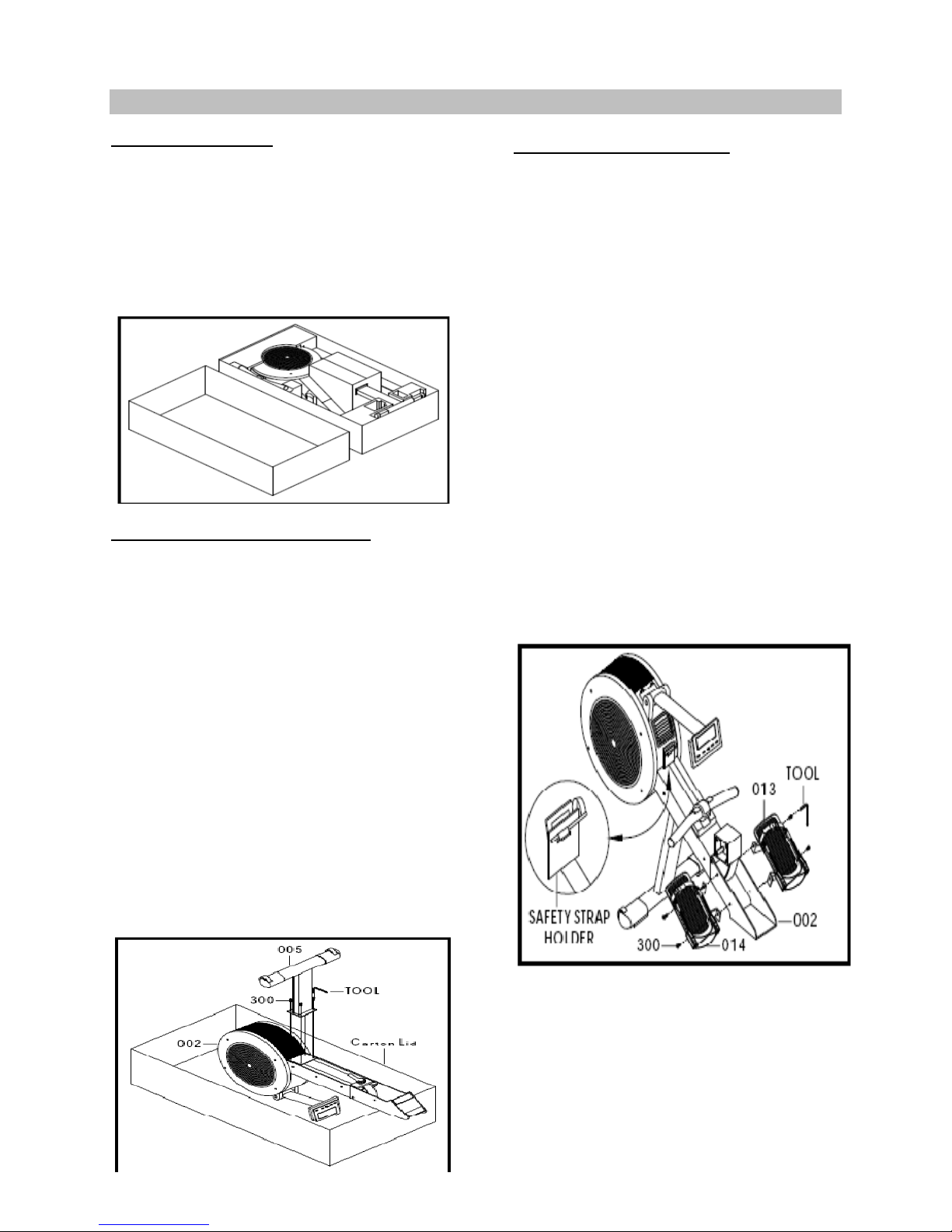
Step 1: Unpackaging
Before assembling your product, distinguish a
proper and appropriate location for the unit.
Clear a big enough working space before
unpacking your LC-R100 Rower. Open the
carton as shown in the diagram below.
Unpackaged all loose components, double
check the packing materials to ensure no
missing parts were left behind.
Step 4:
Step 2: Front Stabilizer Assembly
Note: For SAFETY REASONS: Additional
assistance may be needed to help turn main
frame assembly.
Tools Needed:
6mm Allen wrench
A. Turn the main frame (002) upside down in
the carton as shown in the diagram below.
B. Remove the preassembled Qty. four bolts
(300) from the main frame with the provided
6mm Allen wrench tool.
C. Locate the front stabilizer (005) and
assemble to the main frame, make sure the
wheels face forward. Use the same Qty.
four bolts to secure stabilizer and tighten
bolts firm with the 6mm Allen wrench.
Step 4: Foot Rest Assembly
Note: For SAFETY REASONS: Additional
assistance may be needed to help lift main
frame assembly to the upright position.
Tools Needed:
6mm Allen wrench
A. Turn the rower around to the upright
position as shown in the diagram below.
B. Remove and discard the red safety strap
holder from the pull strap. Place the
handlebar in the holder.
C. Remove the preassembled Qty. four bolts
(300) from the main frame with the
provided 6mm Allen wrench.
D. Locate the left and right foot rests; note
each one is individually marked with “L”
and “R” sticker. Assemble the Right (013)
and Left (014) foot rests to the main frame
with the same Qty. four bolts and tighten
bolts firm.
Page4
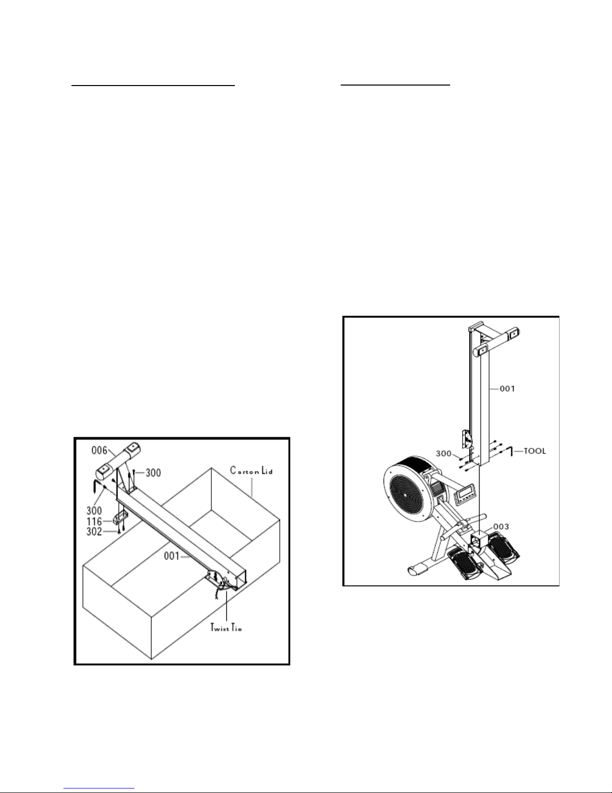
Step 5: Rear Stabilizer Assembly
Tools Needed:
6mm Allen wrench
A. Locate the aluminum beam (001) and place
it on top of the carton lid as shown in the
diagram below.
B. With the tool provided, remove the
preassembled Qty. four bolts (300) from the
aluminum beam and Qty. two bolts (302)
from the rear stabilizer (006).
C. Position the rear stabilizer bar on the
aluminum beam. Secure the stabilizer to
the beam with the same Qty. four bolts
(300). Use the 6mm Allen wrench to tighten
bolts firm.
D. Slide the aluminum beam end cap (116) on
to the rear of the beam and rear stabilizer.
Screw in the Qty. two bolts (302) to the
frame. Use the 6mm Allen wrench to tighten
bolts firm.
E. With a pair of scissors gently cut the zip tie
holding the seat carriage. Discard the zip
tie.
Step 6: Rail Assembly
Note: For SAFETY REASONS: Additional
assistance may be needed to help lift rail on to
frame.
Tools Needed:
6mm Allen wrench
A. Remove the preassembled Qty. eight bolts
(300) from the die cast pivot (003) with the
provided 6mm Allen wrench.
B. Locate the assembled aluminum beam
(001) and gently slide the assembly onto
the main frame (003). Use the same Qty.
eight (300) bolts to secure beam to unit.
Use the 6mm Allen wrench to secure bolts
firm.
Page5
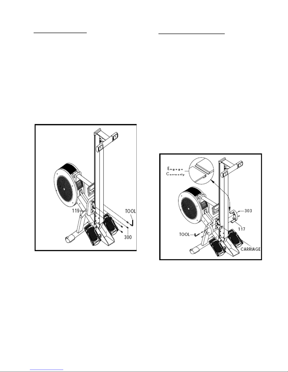
Step 7: Seat Assembly
Tools Needed:
6mm Allen wrench
A. Locate the seat (119) and remove the
preassembled Qty. 4 bolts (300).
B. Position the seat on the seat carriage and
screw in the Qty. four bolts (300).
Note: The pointed portion of the seat should
face forward.
C. Use the 6mm Allen wrench to secure bolts
into place.
Step 8: Seat Carriage Cover
Tools Needed:
Philips screw driver
A. Using the Philips screw driver on the
opposite side of the 6mm Allen wrench, and
remove the Qty. four bolts (303) from the
seat carriage.
B. Locate the two seat carriage covers (117)
and loosely screw the two cover into the
seat carriage using the Qty. four bolts (303).
Note: Ensure that the two seat carriage covers
(117) are engage correctly into each other as
shown in the diagram below.
C. Align the two covers together and make sure
they engage correctly. Finish tightening the
Qty. four bolts (303).
D. Discard and recycle the packaging material
and read the manual thoroughly before
using the rower.
Congratulations!
Assembly for the R100 Rower is complete.
Page6
Setting Up Your Rower
Powering Unit
The R100 has the capacity to run on AC adaptor (ONLY USE A 6v 800mA Adaptor) or 4 C
batteries. To prevent damaged to the electronics, it is recommended to only use one power method
at a time with the R100 rower. Once a power source is connected, the computer will turn on
automatically. If unit goes into a “sleep mode” press any key or pull on the pull strap to activate
computer.
Note: Only use the appropriate power source, never use an adapter that is not certified for the unit, a
wrong adapter or bad batteries will cause the electronics to overheat and malfunction voiding the
warranty.
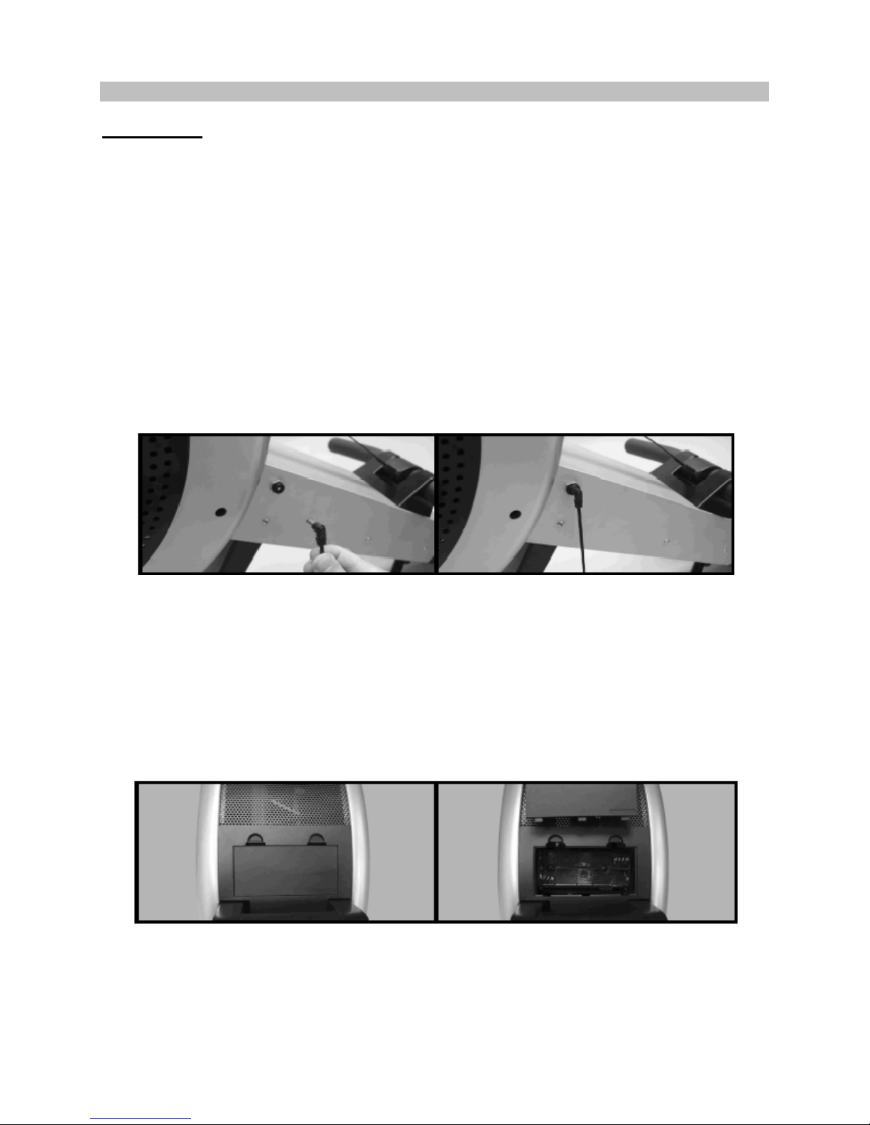
AC Adaptor Power
Attach the power cord jacket into the power socket on the main frame before plugging the power
cord plug into the wall outlet. Flip the ON/OFF switch to the ON position. "0" sign is for OFF; "I" sign
is for ON.
Battery Power
Remove the battery cover on the top of the fan and install four size C 1.5v batteries. Make sure that
the batteries are correctly positioned and properly installed. Reinstall the battery cover. Estimated
battery life is approximately three months under normal use; if the batteries are low, next to the pulse
display a battery symbol will flash when they need to be replaced.
Note: Never mix old and new batteries and never mix different brand of batteries. If unit is going to
be stored for a long period of time, it is mandatory to remove the batteries to prevent damaging the
electrical system.
Note: Display sleep mode: If user stops rowing and there is no RPM or pulse detected for 4 minutes,
the display will shut down and enter a “sleep mode.” To resume, simply press a button on the
console or begin to row. User work out data will be stored in the computer for up to 10 minutes, if
user does not return to work out within this time all data readouts will return to 0.
Page7
Unfolding the Rail
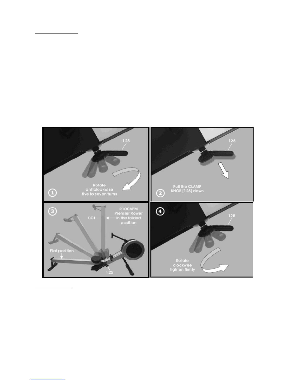
1) Loosen Clamp Knob: (Image 1) While the rower is in the folded position, rotate the clamp knob
(125) counter-clockwise five to seven turns.
2) Lowering the Beam: (Image 2 & 3) Position one hand on the aluminum beam (001) while the
other hand pulls down on the clamp knob to release the safety lock. This will allow the aluminum
beam to lower flat.
3) Tighten Clamp Knob: (Image 4) While the rower is in the flat position, rotate the clamp knob
clockwise to lock beam in place.
WARNING: Never attempt to lower the beam by yourself, ask for additional help if needed and never
attempt to lift the beam if you have any medical issues.
To avoid serious injury, keep finger and hands away from the folding hinge points
Folding the Rail
1) Loosen Clamp Knob: (Image 1) While the rower is in the flat position, rotate the clamp knob
(125) counter-clockwise five to seven turns.
2) Lifting the Beam: (Image 2 & 3) Position one hand on the aluminum beam (001) while the other
hand pulls down on the clamp to release the safety lock. This will allow the aluminum beam to
fold up.
3) Tighten Clamp Knob: (Image 4) While the rower is in the folded position, rotate the clamp knob
clockwise to lock beam in place.
Page8
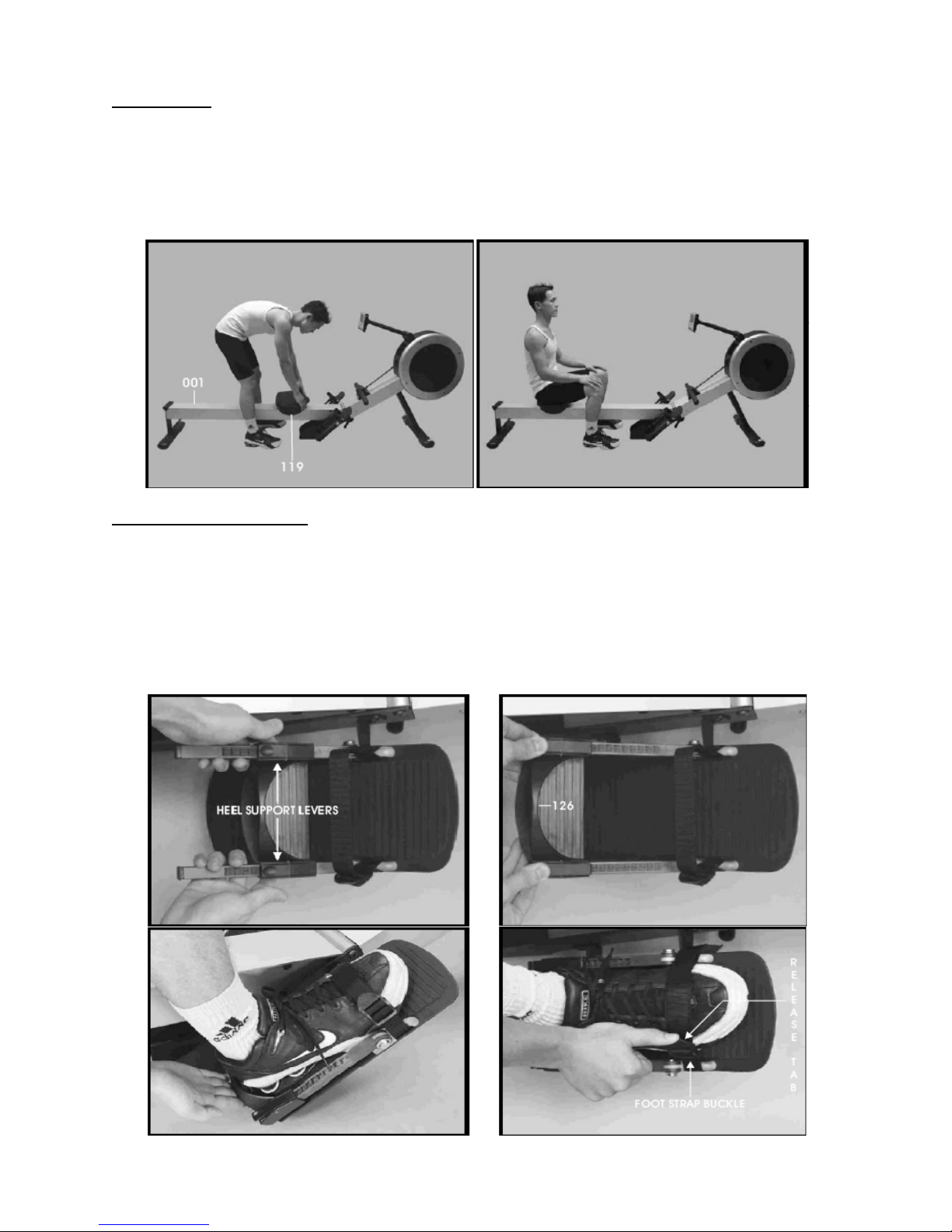
Sitting Down
1) Position yourself in the middle of the aluminum beam (001).
2) Grab the seat assembly and position it below yourself.
3) With one hand on the seat assembly and one hand on the aluminum beam, slowly sit down.
Heel Support Adjustment
1) Squeeze the heel support levers on each side to release the locking mechanism.
2) While squeezing the heel support levers slide the heel support to desired setting. (Number on
the top of the heel support levers is the number that will be set. As illustrated below, adjust the
heel support to allow the foot strap to be across the top of the foot just below the toes.
3) Release the heel support levers to engage the locking mechanism.
Page9
 Loading...