

LifeCore Fitness LC-CD450 User's Product Manual

User’s Product Manual
LifeCORE LC-CD450 Center Drive Elliptical
Introduction
Congratulations on your purchase of the CD450 Center Drive Elliptical. This product has been
designed and manufactured to meet the needs and requirements of domestic use.
By Choosing your CD450 Elliptical, you have made a wise decision that will improve the health of
you and your family. Being fit and healthy will improve your energy level and your quality of life.
Cardiovascular training is vital for all ages and the CD450 Elliptical provides a more effective
workout, producing better results, and will encourage you to reach your fitness goals and maintain
the body you have always wanted.
In order to make your experience with LifeCORE the best it can be, please review the enclosed
user’s manual prior to assembly and first use. Be sure to keep the instructions for reference and/or
maintenance.
We also offer a complete line of fitness equipment; please take a moment to review our other
excellent products at www.LifeCOREfitness.com. Should you have any questions, please contact us.
Your feedback and ideas about your experience with LifeCORE are also very important to us. Write
to us at:
LifeCORE Fitness Inc.
2575 Pioneer Ave. Suite 101
Vista, CA 92081
We wish you lots of success and fun while training!
Purchaser’s Reference Information
Please send in the attached warranty card and a copy of the original receipt or register online
at www.LifeCOREfitness.com within (10) days of purchase to register your product with
LifeCORE Fitness.
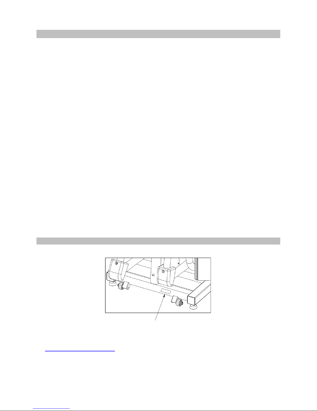
Serial Number is located on the frame
Page | 1

Introduction…………………………………………………………………………………….............
Purchaser’s Reference Information ………………………………………………………………….
Table of Contents………………………………………………………………………………………
Safety instructions and Warnings…………………………………………………………………….
Assembly Instructions …………………………………………………………………………………
Console Operation Instructions ………………………………………………………………………
English and Metric Setting ……………………………………………………………………………
Touch Screen Adjusting Steps ……………………………………………………………………….
Monitoring Your Heart Rate ………………………………………………………………………….
Heart Rate Monitoring Devices ………………………………………………………………………
Care and Maintenance ……………………………………………………………………………….
Warranty Card………………………………………………………………………………………….
1
1
2
3
4
12
19
19
20
21
22
23
Table of Contents
Page | 2

Safety Instructions & Warnings
The CD450 Elliptical is designed and manufactured to meet or exceed all domestic and international
safety standards. However, certain precautions need to be followed when operating any exercise
equipment.
General safety instructions:
1. It is important to consult your physician before any exercise program.
2. Pregnant women should consult with their physician before beginning any exercise program.
He/she can help determine the exercise program that is the most appropriate for your age and
physical condition.
3. If you experience dizziness, nausea, chest pains or other abnormal symptoms during exercise,
stop the exercise session immediately. Consult your physician before continuing your exercise.
4. Keep children away from the equipment. Hands and feet may get caught in the pedals or other
moving parts, which could result in serious injury.
5. No more than one person should ever use the product at a time.
6. Pets should never be allowed near unit.
7. Always wear proper clothing and shoes when exercising. Drink plenty of fluids when exercising.
8. Always stretch and warm up before starting any exercise program.
9. Never operate this unit if it is damaged or broken. Contact your authorized dealer for service.
10. Place your equipment on a solid, level surface when in use.
11. Place your unit in an area with enough clearance to operate the equipment.
12. Make sure all components are fastened securely at all times.
Product safety instructions:
1. Start your exercise program gradually. Exercise only for a few minutes the first day to let your
body adjust to the new exercise.
2. Slowly increase your exercise time and intensity over the first two weeks. If you increase your
intensity too rapidly, or fail to warm up properly, you can increase the risk of injury.
3. Use of this machine with worn or weakened parts, may result in injury to the user. We strongly
suggest replacing it immediately. Use only the accessory attachments recommended by the
manufacturer.
4. Unit maximum weight limit is 300LBS
5. It is recommended the unit be plugged into a surge protector.
6. Whenever mounting or dismounting from the exercise machine, make sure that the unit is not in
motion and use caution to prevent injury. Use the handlebars or a helper whenever additional
stability is required.
7. Never place any open containers of any type directly on the unit, only containers with lids are
recommended to be used with the appropriate water bottle holder.
8. Keep machine clear of any obstructions, heavy machinery, and never place objects on or against
machine.
9. Do not place machine in an area of high voltage or electromagnetic fields.
10. DANGER: Always unplug the power cord before performing maintenance.
11. Failure to follow these instructions will void the units warranty and the manufacturer or distributor
assumes no responsibility for personal injury or property damages related to the product if unit is
ever used incorrectly or for reasons other than exercise.
12. Perform proper maintenance as recommended in this manual.
13. Save this manual for future reference.
Page | 3
Assembly Instructions
Figure 3
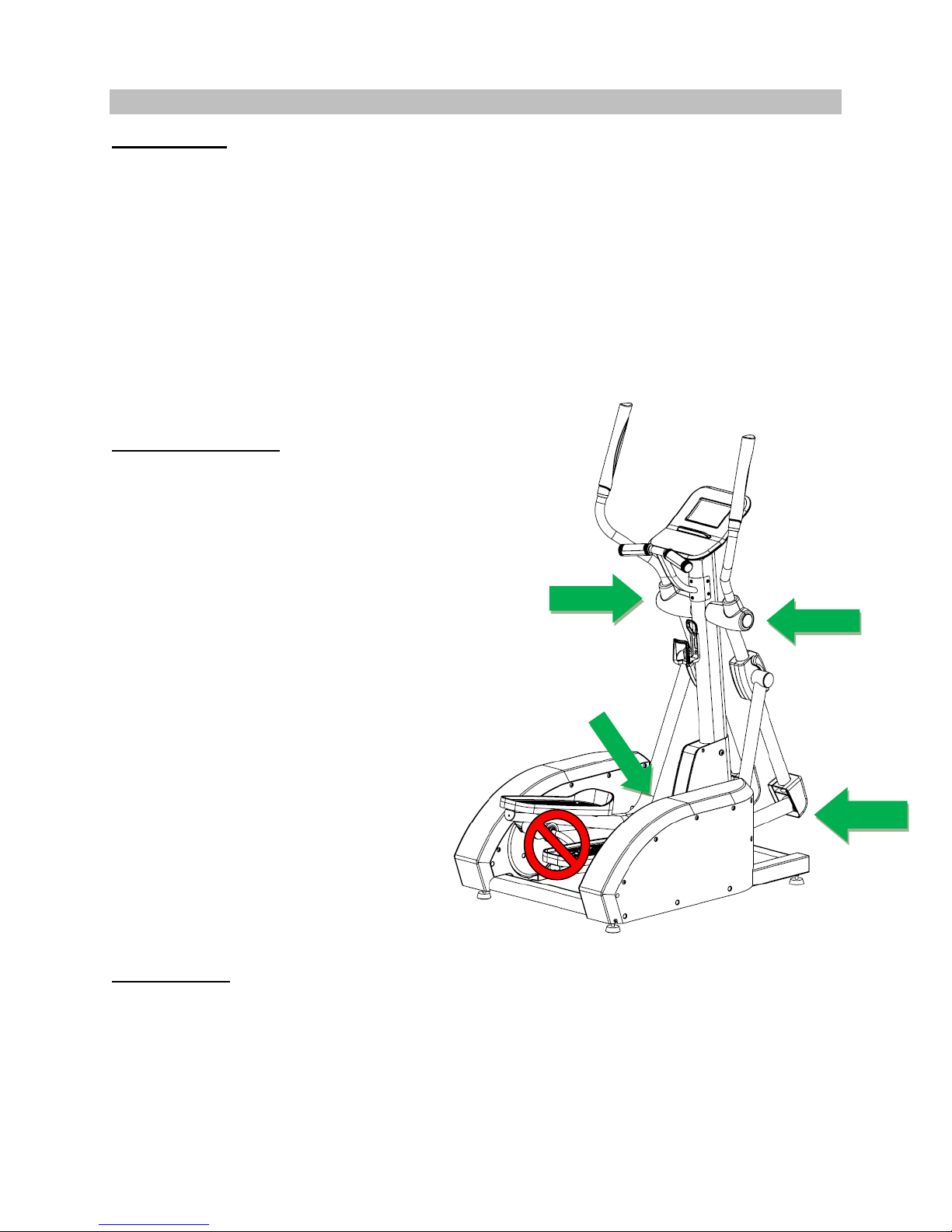
Assembly Assistance
In each CD450 assembly pack, there is a
tube of grease for assembly purposes. This
tube of grease must be applied to the pivot
points during assembly. At no time
should this grease be applied on to the
rubber wheels parts #2CUB Shaft Wheel
w/ball bearing.
Figure 3 – Green Arrows
During Step 3 assembly, apply grease to
the console tube pivot points on each
side. Once the arms are secure, apply
some additional grease to the bearings,
then secure arm with Figure 3 hardware.
Figure 5 – Green Arrows
During Step 5 assembly, apply grease to
the pedal tube and handrail assembly tube
pivot point on each side. In addition,
apply grease to the M10 * 81.5 Hex Bolt.
NOTE: DO NOT USE WD-40 OR
SILICONE SPRAY – This will increase
squeaking noise.
Figure 3
Figure 5
Assembly Tips
The LifeCORE CD450 is made from the best materials and has been tested and received a quality
control review prior to its packaging to ensure the correct parts and proper fitting of each component.
This machine was designed to limit the amount of assembly needed by a consumer.
Before assembly of your product, distinguish a proper and appropriate location for the unit where
there is easy access to an electrical outlet with a surge protector. Unpack the box in a clear work
area to allow smooth assembly. Remove all of the parts from the packing material; however, do not
discard packing material until assembly is complete. Double check packing materials to ensure no
missing parts were left behind.
Note that some hardware may be preassembled to components in order to help with assembly; tools
have also been provided to assist with assembly.
Getting Started
Unpack the box in a clear location, remove all packaged parts from the box and lay each part out on
the floor. Double check all packaging material for missing pieces, do not dispose of any packing
material until assembly is complete and unit is working properly. The final location of the machine
should be placed on a clean level surface near an electrical outlet.
Hardware Bags - Locate all hardware bags for assembly. Bags will be labeled Figure 1 through
Figure 11. Tools have been provided to assist with product assembly.
Page | 4
Step 1:
Tools Needed:
6mm Allen wrench: 2JC7
17 mm socket wrench: 2JAX
Note: Ensure that all wires are properly
connected inside console tube. Be careful to
not pinch wires. Additional help maybe
needed to help line up holes to frame.
Note: Do not tighten screws until you
have fully completed Step 2.
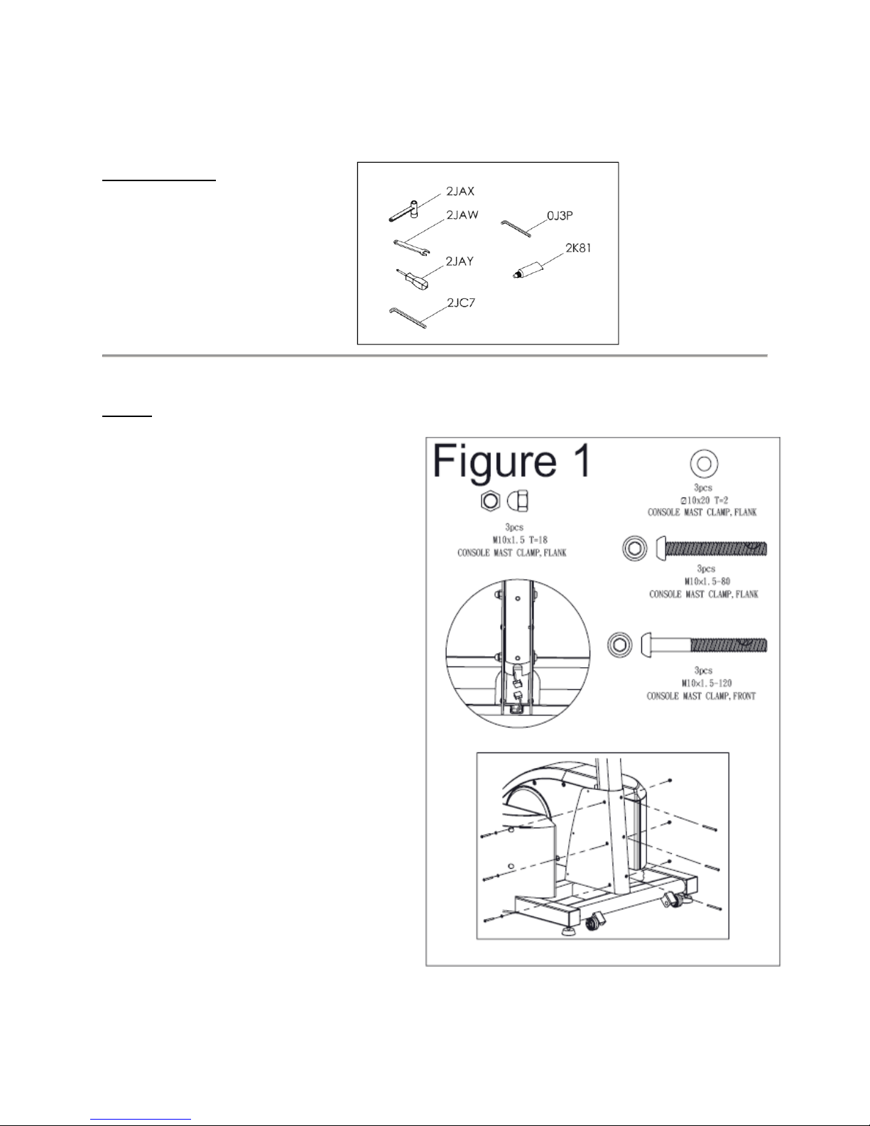
1) Locate bag labeled Figure 1.
2) Locate console tube.
3) Slide console tube into main frame.
4) (See Figure 1) Connect upper console
wire to lead wire assembly coming from
frame.
5) Secure console tube to frame using Qty.
three 10x20 washers and three
M10x80mm short hex head bolts and
extend them through the holes on the
right side of the frame and console tube.
Use Qty. three M10x1.5 crown nuts to
lock M10x80mm hex head screws on
left side.
6) Use Qty. three M10x120 long hex bolts
to secure console tube to the main
frame.
If you are missing any parts, assembly bags or need assistance with assembly please call LifeCORE
Fitness at 1-888-815-5559.
Tools Required:
17 mm socket wrench: 2JAX
17 mm wrench: 2JAW
Philips screw driver: 2JAY
6mm Allen wrench: 2JC7
4mm Allen wrench: 0J3P
Tube of grease: 2K81
Page | 5
Step 2:
Tools Needed:
Philips Screw driver: 2JAY
1) Locate bag labeled Figure 2.
2) Locate black metal cover.
Note: First fasten screws at the bottom of the
cover, next top and finally the middle.
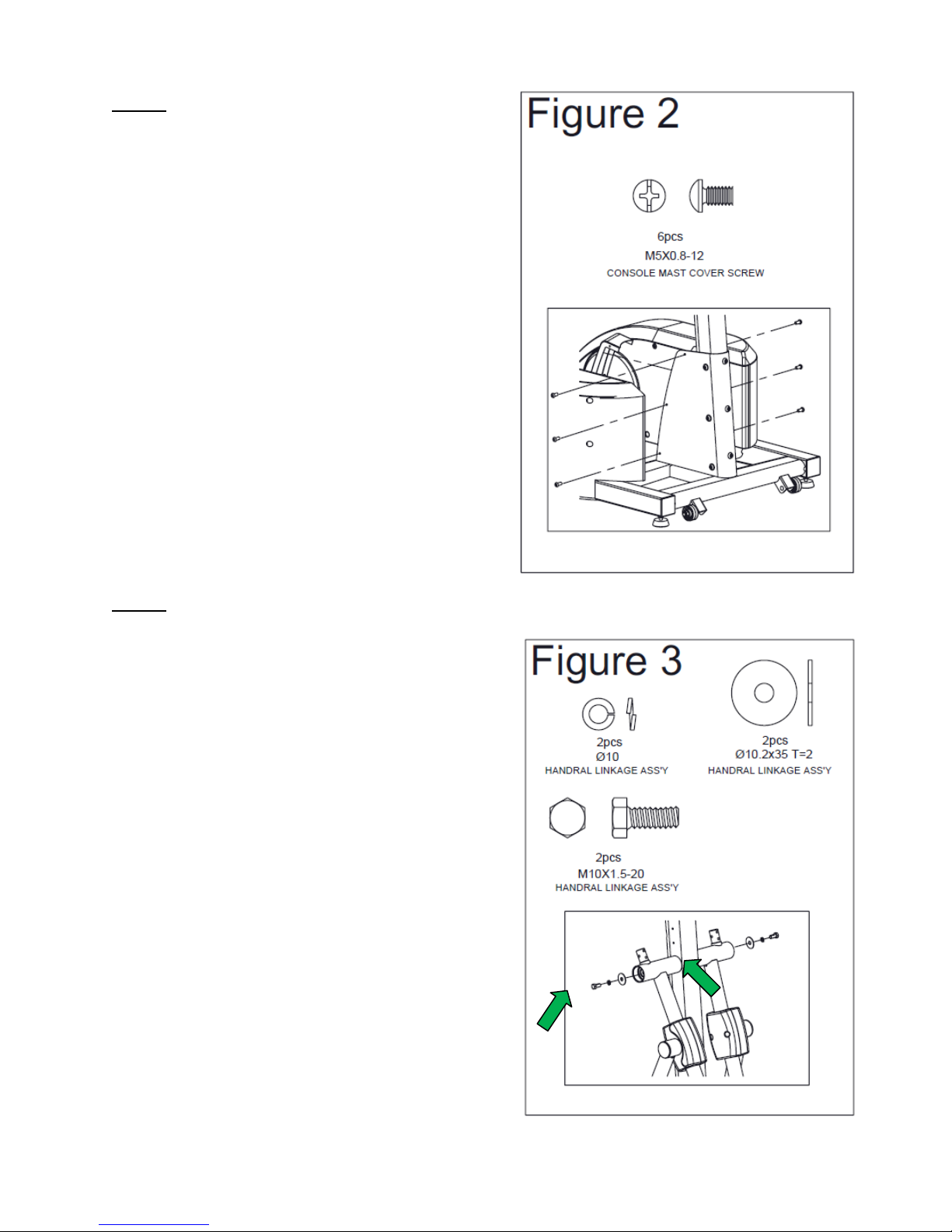
3) (See Figure 2) Secure cover to main
frame by using Qty. six M5x0.8-12
screws. Screw two at the bottom of the
cover, next screw two on top and finally
two in the middle. Using a Philips screw
driver, tighten screws.
4) Tighten all hardware from Step 1.
Step 3:
Tools Needed:
17 mm socket wrench: 2JAX
Tube of grease: 2K81
Note: Arms are labeled Right and Left.
Note: Apply about a finger tips worth of
assembly grease on each pivot point shaft
and bearings prior to connecting arms.
1) Locate bag labeled Figure 3.
2) Locate the left and right handrail
assemblies.
3) (See Figure 3) Apply and spread grease
on console tube shafts. Mount the left and
right handrail assemblies to console tube
using one washer first, one spring washer
second and one M10*20 hex bolt last on
each side. Using a 17 mm socket wrench,
tighten hex bolts.
Page | 6
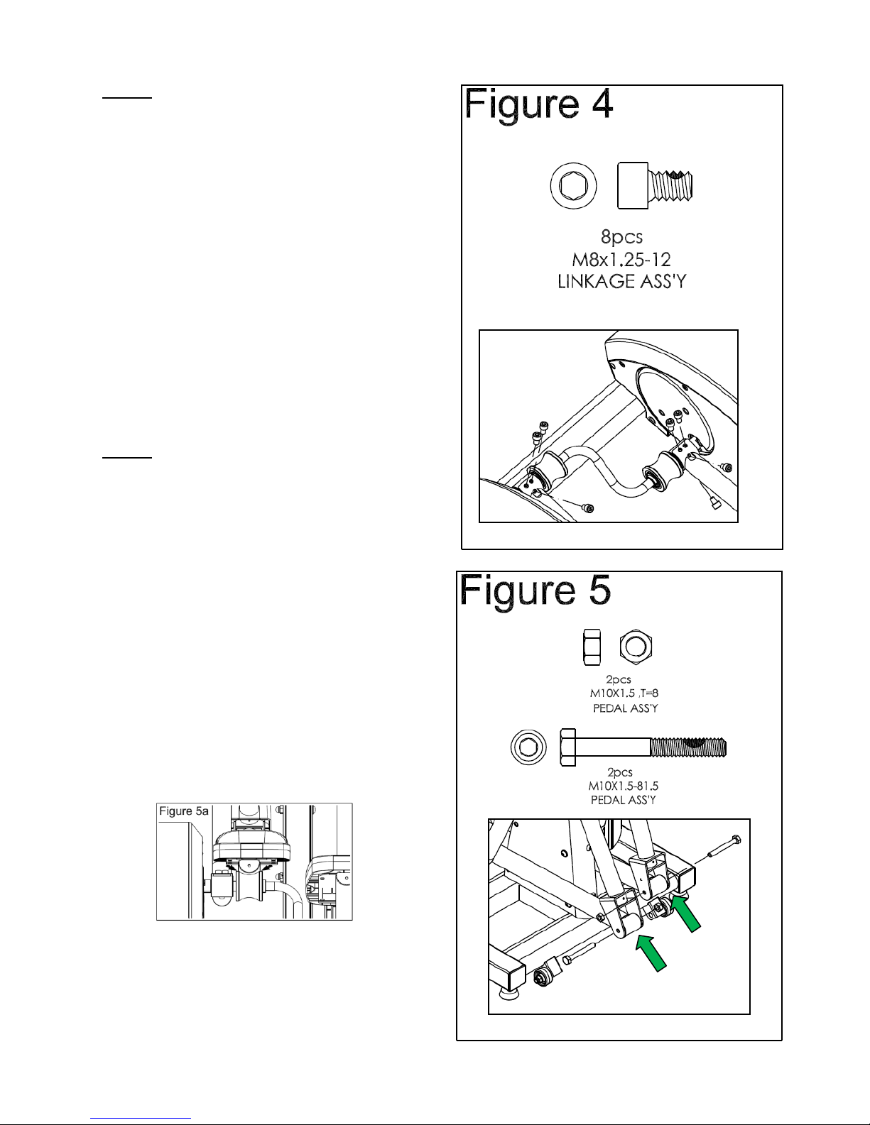
Step 4:
Tools Needed:
6mm Allen wrench: 2JC7
1) Locate bag labeled Figure 4.
Note: Additional help may be needed to help
align holes on top and bottom.
2) (See Figure 4) Lift and place left linkage
handrail assembly onto shaft sleeve.
Make sure all four bolts line up. Screw
Qty. two M8x12mm hex bolts to the top
and bottom holes. Using a 6mm Allen
wrench, tighten the bolts.
3) Repeat same steps for right side.
Step 5:
Tools Needed:
17 mm socket wrench: 2JAX
17 mm wrench: 2JAW
Tube of grease: 2K81
Note: It is recommended that two adults help
align and secure the pedal tube assemblies to
the handrail assemblies.
Note: Apply about a finger tips worth of
assembly grease on each pivot point bolt
shaft and bearings prior to connecting arms.
1) Locate bag labeled Figure 5.
Note: Please ensure that pedal arm is aligned
in the center of roller wheel while tightening all
hardware. Repeat for the left side.
2) (See Figure 5) Locate right pedal tube
assembly and secure to the handrail
assembly with Qty. one M10x81.5 hex
bolt and Qty. one M10x1.5 hex nut. Using
a 17 mm socket wrench & 17 mm wrench,
tighten the bolts.
Page | 7
 Loading...