

LifeCore Fitness LC-985VGS User's Product Manual
User’s Product Manual
OM Edition 3 LifeCore LC-985VGS Elliptical

Introduction
Congratulations on your purchase of the LC-985VGS elliptical. This product has been designed and
manufactured to meet the needs and requirements for domestic use.
By choosing the 985VG elliptical, you have made a wise decision which will improve your health as
well as your families. Being fit and healthy will improve your energy level and your quality of life.
Cardiovascular training is vital for all ages and the LC-985VGS elliptical provides a more effective
workout, producing better results, and will encourage you to reach your fitness goals and maintain
the body you have always wanted.
In order to make your experience with LifeCORE the best it can be, please review the enclosed
user’s manual prior to assembly and first use. Be sure to keep the instructions for reference and/or
maintenance.
We also offer a complete line of fitness equipment; please take a moment to review our other
excellent products at www.LifeCOREfitness.com. Should you have any questions, please contact us.
Your feedback and ideas about your experience with LifeCORE are also very important to us.
Please write to us at:
LifeCORE Fitness Inc.
2575 Pioneer Ave. Suite 101
Vista, CA 92081
We wish you lots of success and fun while training!
Purchaser’s Reference Information
Please send in the attached warranty card and a copy of the original receipt or register online
at www.lifecorefitness.com within (10) days of purchase to register your product with
LifeCore Fitness.
Serial Number is located on the frame
Page | 1

Introduction…………………………………………………………………………………….............
Purchaser’s Reference Information ………………………………………………………………….
Table of Contents………………………………………………………………………………………
Safety instructions and Warnings…………………………………………………………………….
Assembly Instructions…………………………………………………………………………………
Setting Up Your Elliptical …………………………………………………………………………….
Correct Exercising Guide …………………………………………………………………………....
Console Operation Instructions ………………………………………………………………………
Calculating Target Heart Rate ……………………………………………………………………….
Heart Rate Monitoring Devices………………………………………………………………………
Care and Maintenance ……………………………………………………………………………….
Error Message Guide..……………………………………………………………………………….
Parts List & Parts Diagram……………………………………………………………………………
Warranty Card………………………………………………………………………………………….
1
1
2
3
4
7
9
11
17
18
19
19
20
22
Table of Contents
Page | 2

Safety Instructions & Warnings
The LC-985VGS elliptical is designed and manufactured to meet or exceed all domestic and
international safety standards. However, certain precautions need to be followed when operating any
exercise equipment.
General safety instructions:
1. It is important to consult your physician before any exercise program.
2. Pregnant women should consult with their physician before beginning any exercise program.
He/she can help determine the exercise program that is the most appropriate for your age and
physical condition.
3. If you experience dizziness, nausea, chest pains or other abnormal symptoms during exercise,
stop the exercise session immediately. Consult your physician before continuing your exercise.
4. Keep children away from the equipment. Hands and feet may get caught in the pedals or other
moving parts, which could result in serious injury.
5. No more than one person should ever use the product at a time.
6. Pets should never be allowed near unit.
7. Always wear proper clothing and shoes when exercising. Drink plenty of fluids when exercising.
8. Always stretch and warm up before starting any exercise program.
9. Never operate this unit if it is damaged or broken. Contact your authorized dealer for service.
10. Place your equipment on a solid, level surface when in use.
11. Place your unit in an area with enough clearance to operate the equipment.
12. Make sure all components are fastened securely at all times.
Product safety instructions:
1. Start your exercise program gradually. Exercise only for a few minutes the first day to let your
body adjust to the new exercise.
2. Slowly increase your exercise time and intensity over the first two weeks. If you increase your
intensity too rapidly, or fail to warm up properly, you can increase the risk of injury.
3. Use of this machine with worn or weakened parts, may result in injury to the user. We strongly
suggest replacing it immediately. Use only the accessory attachments recommended by the
manufacturer.
4. Unit maximum weight limit is 300LBS
5. It is recommended the unit be plugged into a surge protector. Do not place machine in an area of
high voltage or electromagnetic fields.
6. Whenever mounting or dismounting from the exercise machine, make sure that the unit is not in
motion and use caution to prevent injury. Use the handlebars or a helper whenever additional
stability is required.
7. Make sure that all components are fastened securely including but not limited to seat, pedals,
handlebars, or any electric components.
8. Never place any open containers of any type directly on the unit, only containers with lids are
recommended to be used with the appropriate water bottle holder.
9. Keep machine clear of any obstructions, heavy machinery, and never place objects on or against
machine.
10. DANGER: Always unplug the power cord before performing maintenance.
11. Failure to follow these instructions will void the units warranty and the manufacturer or distributor
assumes no responsibility for personal injury or property damages related to the product if unit is
ever used incorrectly or for reasons other than exercise.
12. Perform proper maintenance as recommended in this manual.
Page | 3
Assembly Instructions
Before assembling your product, distinguish a
proper and appropriate location for the unit
where there is easy access to an electrical
outlet with a surge protector. Clear a big
enough working space before unpacking your
LC-985VG Elliptical.
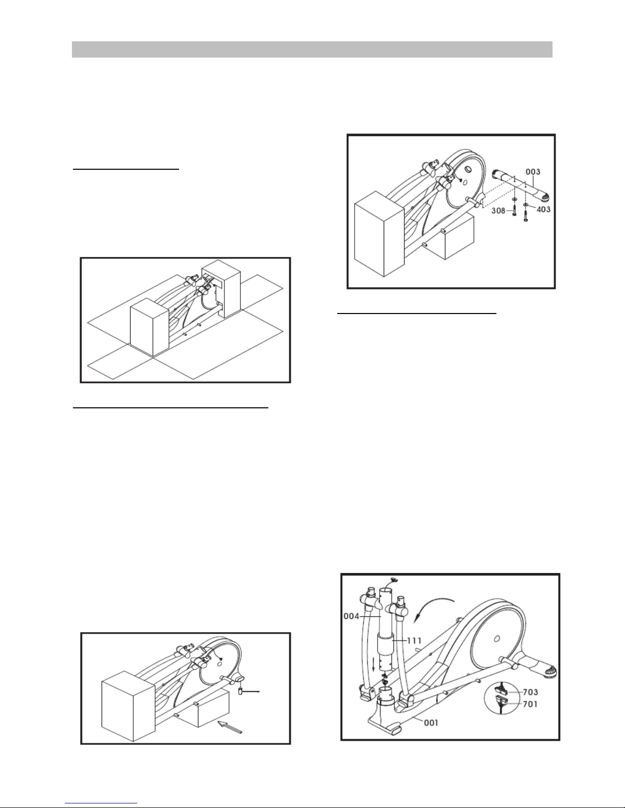
Step 1: Unpackaging
A. Using a knife, gently open the carton and
cut the sides so it lays flat on the floor as
illustrated below. Unpackaged all loose
components. Double check the packing
materials to ensure no missing parts were
left behind.
Step 3: Rear Stabilizer Tube Assembly
Note: For SAFETY REASONS: Additional
assistance may be needed to help lift main
frame assembly.
Tools Needed:
14mm wrench
B. Remove the rear polystyrene packaging
and lift the rear of the machine off the floor.
Slide the packaging under the rear end of
the machine as illustrated below.
C. With the rear end of the machine now
raised off the floor; use a 14mm wrench to
undo Qty. 2 bolts (308) and Qty. 2 washers
(403). Discard the red transportation tube.
A. Assemble the rear stabilizer tube (003) with
the same 2 bolts (308) and 2 washers (403),
tighten bolts firm. Remove the rear
polystyrene packaging from under the unit.
Step 5: Upright Tube Assembly
Note: For SAFETY REASONS: Additional
assistance may be needed to help lift upright
tube onto main frame assembly.
A. Remove the front polystyrene packaging.
Note: Make sure that all wires are connected
together properly, and cover (111) is on upright
tube before positioning upright tube.
B. As illustrated below, connect computer
cable (703) to motor with cable wire (701).
Make sure wires are connected together
properly. With assistance from another
person, carefully lift the upright tube (004)
and slide the upright tube into the main
frame (001). Push and store excess wires
back into the upright tube (004). Be careful
not to pinch the wires.
Step 4:
Page | 4
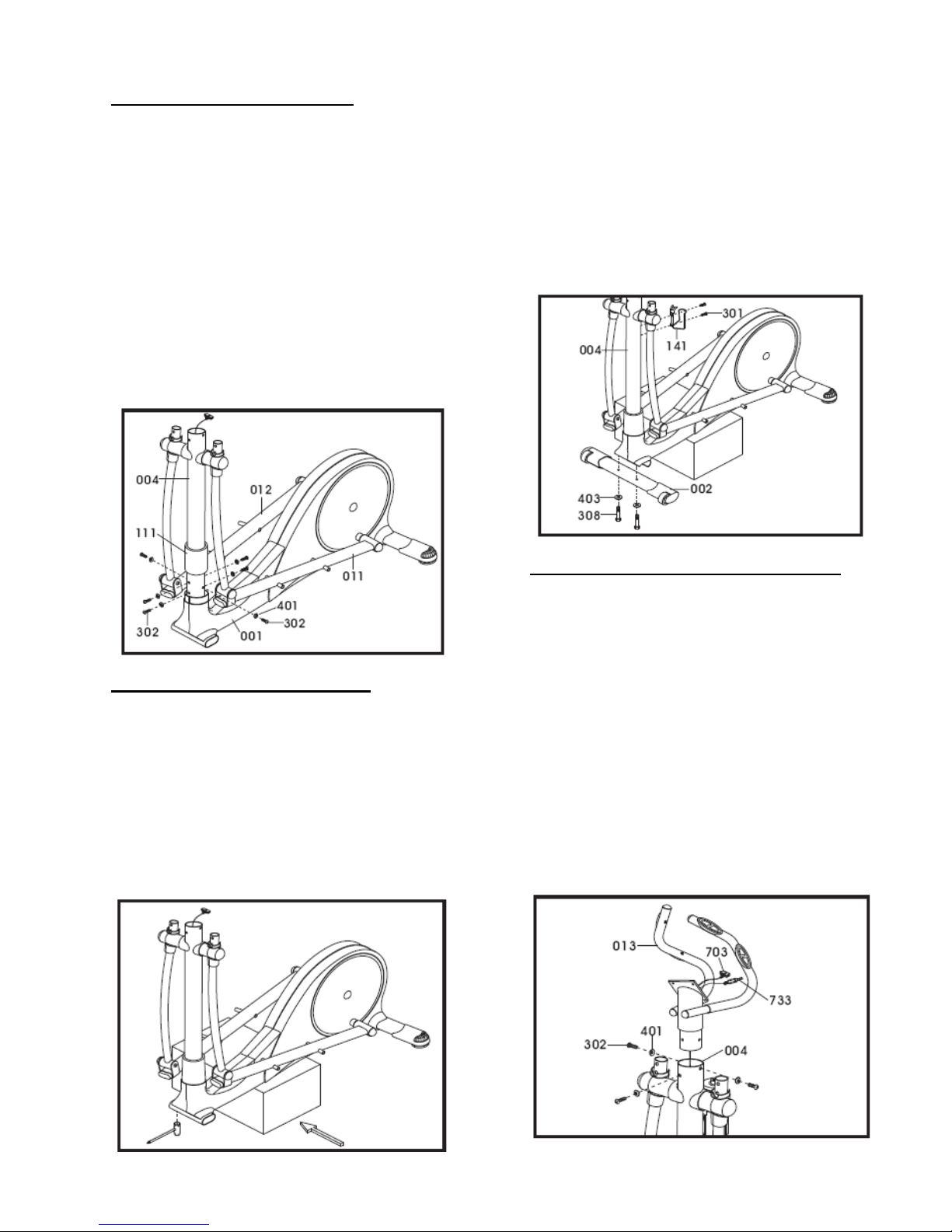
Step 6: Upright Tube Assembly
Tools Required:
6mm Allan wrench
A. Locate hardware bags labeled (Part: #302
bolt (M8x15) & #401 washers (M8x19x1.5)
As illustrated below, lift up cover (111) and
assemble Qty. 6 bolts (302) and washers
(401) into main frame (001). If needed,
rotate the foot pedal tubes (011 & 012) for
easier access to side bolts. Using a 6mm
Allen wrench, firmly tighten the 6 Allen
bolts.
B. Slide hat cover (111) into position.
Step 7: Front Stabilizer Assembly
Tools Needed:
14mm wrench
Philips screw driver
A. Place a polystyrene block under front of
unit, now with the front of the machine
raised off the floor; use a 14mm wrench to
undo Qty. 2 bolts (308) and Qty. 2 washers
(403). Discard the red transportation tube.
B. Assemble the front stabilizer tube (002) with
the same 2 bolts (308) and 2 washers
(403), tighten bolts firm.
C. Remove the polystyrene block and discard.
D. Using a Philips screw driver, remove
preinstalled Qty. 2 screw (301) from upright
tube (004). Align water bottle holder (141)
and fasten with the same 2 screws.
Step 9: Stationary Handle Bar Assembly
Tools Needed:
6mm Allan wrench
A. Located stationary handle bar (013) and
loosen preassembled Qty bolts (302) and
Qty. 3 washers (401). Feed both the
computer cable (703) and hand pulse cable
(733) out through the top of the stationary
handle bar (013). Slide the stationary
handle bar into the upright tube (004).
B. Secure stationary handle bar with the same
Qty. 3 bolts (302) and 3 washers (401)
previously removed. Use a 6mm Allan
wrench to tighten bolts firm.
Page | 5
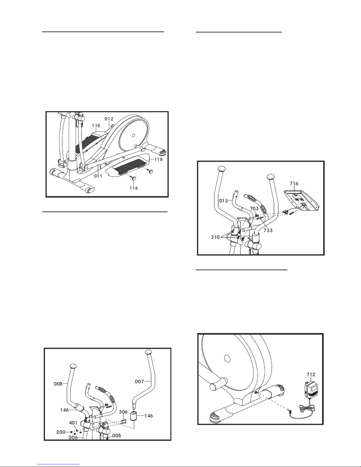
Step 10: Adjustable Foot Pedal Assembly
A. As illustrated below, locate and slide the
adjustable foot pedals (115) onto the left
and right foot pedal tubes (011 & 012).
Locate and tighten foot pedal knobs (116)
to the adjustable foot pedals to firmly
secure them in place. Note: The adjustable
foot pedals can be adjusted to your
personal preference; however, we suggest
starting with the middle setting number 3.
Step 11: Dual Action Handle Bar Assembly
Tools Needed:
13mm wrench
A. As illustrated below, slide the top pivot
covers (146) to the dual action handles
(007) & (008).
B. Insert the dual action handles (007 & 008)
into the top of dual action arm (005 & 006)
Note: Left and Right stickers on handle
bars.
C. Locate hardware bags and secure with Qty.
4 bolts (306), Qty. 4 washers (401) and Qty.
4 nuts (200). Using a 13mm wrench, tighten
nuts firm. Slide top pivot covers over
hardware.
Step 12: Computer Assembly
Tools Needed:
Philips screw driver
A. Locate computer console (716) and
connect computer cable (703) and hand
pulse cable (733) to the computer.
B. Feed the excess cables back in the
stationary handle bar (013). Be careful not
to pinch wires.
C. Unscrew Qty. 4 computer screws from the
back of the console, and fix the console to
the top of the stationary handle bar (013).
Using a Philips screw driver, tighten the
Qty. 4 computer screws to console firm.
Step 13: Power Cord Assembly
A. Attach the AC adaptor jacket into the
power socket on the main frame before
plugging the power cord plug into the wall
outlet. Turn the AC power switch on. Flip
the ON/OFF switch to the ON position. "0"
sign is for OFF; "I" sign is for ON.
Page | 6
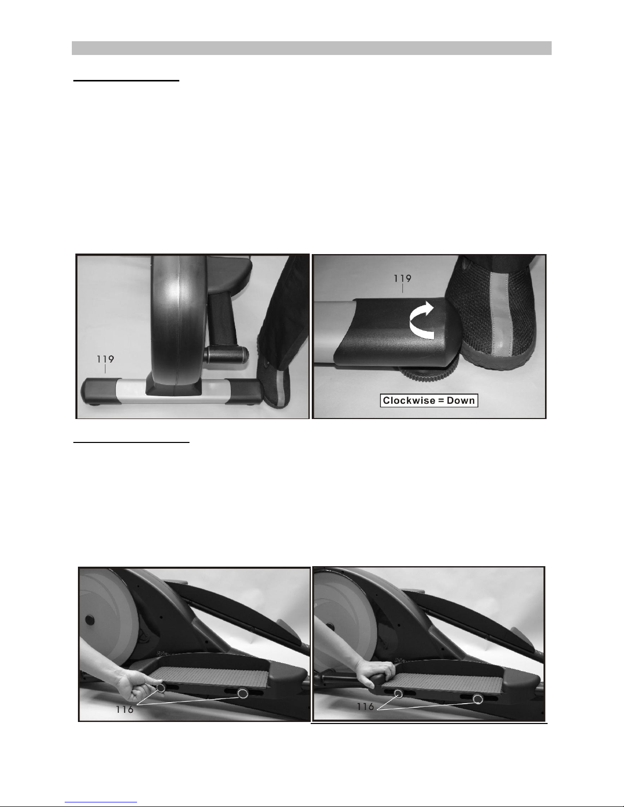
Setting Up Your Elliptical
Height Adjuster Cap
Important: Make sure that the LC-985VGS is always positioned in a location that has a solid level
floor. It is recommended that if this elliptical is being placed on a hardwood, tile or any delicate
surface that a protective mat is placed under the machine to help prevent damaged to the
machine and/or damage to the flooring surface. Please contact your dealer to purchase a
compatible mat for this machine.
1) To stabilize your elliptical, first make sure the left and right front stabilizer wheel caps (112 &
113) are touching the ground.
2) Determine which side of the machine is unstable. Using the rear stabilizer caps (119) in the back
of the machine, adjust the dial clockwise (lower) or counter-clock wise (Lift) to help lift or lower
the back of the machine to stabilize it.
Foot pedal Adjustment
1) To adjust the foot pedals, simply loosen Qty. 2 foot pedal knobs (116) on each side of the foot
pedals.
2) Slide the adjustable foot pedals (115) to the desired setting using the number labels as a guide.
(1-5) Slide the edge of the adjustable foot pedal to the gray line of desired number. Note: To
prevent injury, make sure that each foot pedal is adjusted to the same number.
3) Retighten foot pedal knobs (116) firmly on both sides of the adjustable foot pedal.
Page | 7
 Loading...