

LifeCore Fitness LC 950 RB User's Product Manual
1
User Product Manual
LifeCore LC-950 Recumbent Bike
Customer Service
Toll Fee (888) 815 – 5559
Service@lifecorefitness.com
www.lifecorefitness.com
LifeCore Fitness Inc.
2575 Pioneer Avenue, Suite 101,
Vista, CA 92081
LC 950 RB
Visit our website for assembly videos: www.lifecorefitness.com

2
Important Safety Instruction
We at LifeCore fitness would like to thank you for your recent purchase of a LifeCore exercise
bike, and we hope that our product inspires and motivates you to accomplish your fitness
goals. Please read the users owners manual and orient yourself with the unit before you use
the product to get a better understanding of your exercise machine.
The LifeCore 950RB is an exercise bike that simulates the movements of riding a bicycle at
different speeds and resistance levels. Before the machine is ever used, it is recommended
that a physician be consulted regarding any user(s) health condition, especially if the user(s)
has a family history of cardio vascular conditions. If, at any time while exercising, a user
experiences shortness of breath, dizziness, faintness, chest pains, or any discomforts, he or she
must stop immediately and contact his or her physician.
It is the sole responsibility of the owner(s) to make sure that any user using this product
has fully read and understands the warnings and safety precautions.
Unit maximum weight limit is 300LBS.
Before working out remember to perform stretching exercises to avoid injury.
Do not use this exercise bike outdoors or in areas of high humidity.
Only operate the machine in a dry well ventilated room.
Always examine the unit prior to exercising to ensure parts are in good working order.
After every workout use the preventative maintenance tips to keep the products in
good working order.
Make sure that all components are fastened securely including but not limited to seat,
pedals, handlebars, or any electric components.
Unit should always be plugged into a surge protector.
No more than one person should ever use the product at a time.
Pets should never be allowed near unit.
Children should never be left unsupervised near unit.
Always use appropriate clothing and shoes to exercise. Never use heels, spikes, cleats,
bare feet, sandals, socks or stockings while using the exercise machine.
Keep hands and feet away from any moving parts at all times.
Make sure that the unit is on a solid level surface. It is recommended that a mat be
placed under the machine to protect the floor, carpet or any solid surface that the
machine is placed on. Also to protect the machine from a hard surface.
Whenever mounting or dismounting from the exercise machine, make sure that the unit
is not in motion and use caution to prevent injury. Use the handlebars or a helper
whenever additional stability is required.
Never place any open containers of any type directly on the unit, only containers with
lids are recommended to be used with the appropriate water bottle holder.
Keep exercise bike clear of any obstructions, heavy machinery, and never place
objects on or against machine.
Do not place machine in an area of high voltage or electromagnetic fields.
Failure to follow these instructions will void the units warranty and the manufacture or
distributor assumes on responsibility for personal injury or property damages related to
the product if unit is ever used incorrect or for other reasons other than exercise.
3
G
2L
3L
1L
2E
9A
2A
5E
6E
D
1D
3E
4E
1E
1-1E
2-1F
2-5A
1F
1-5A
1-1F
2M
2-2M
3-2M
1-2M
51A
61A
01A
2B
2-1F
4B
5B
1B
4-1A
3B
6B
7B
8B
11A
3-11A
2-11A
21
A
1-21A
3-21A
2-21A
31A
4-21A
5-21A
3C
2C
1C
4C
5C
1A
5-1A
1-1A
A1-2
N
71A
1-71A
P
4A
1-4A
2-4A
3-4A
4-4A
5-4A
3-5A
5A
1-5A
2-5A
4-5A
5-5A
6-5A
7-5A
8-5A
9-5A
01-5A
11-5A
21-5A
31-5A
8A
3F
2F
1-2F
K
1K
3F
2H
1H
41A
1-41A
1M
1-1M
3-1M
2-1M
1J
3J
2J
3J
4J
6A
1-6A
2-6A
2K
5J
G2
G3
A3
A1-3

4
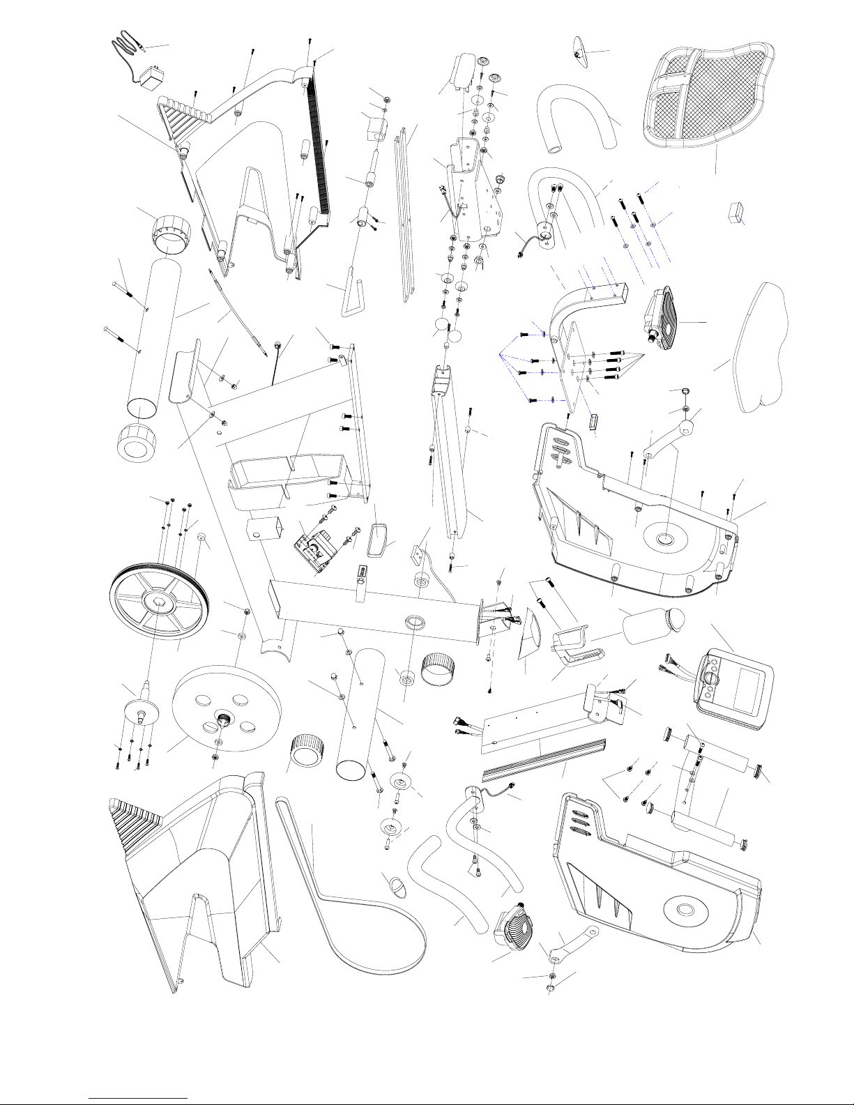
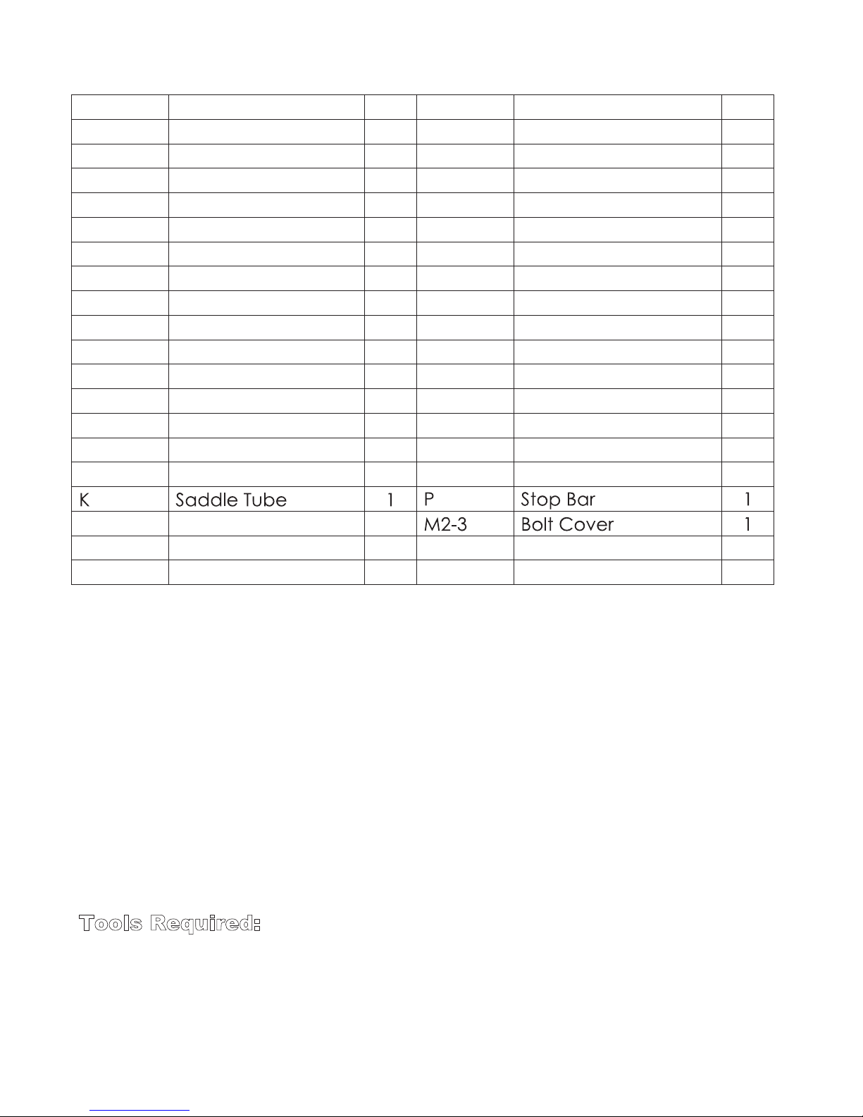
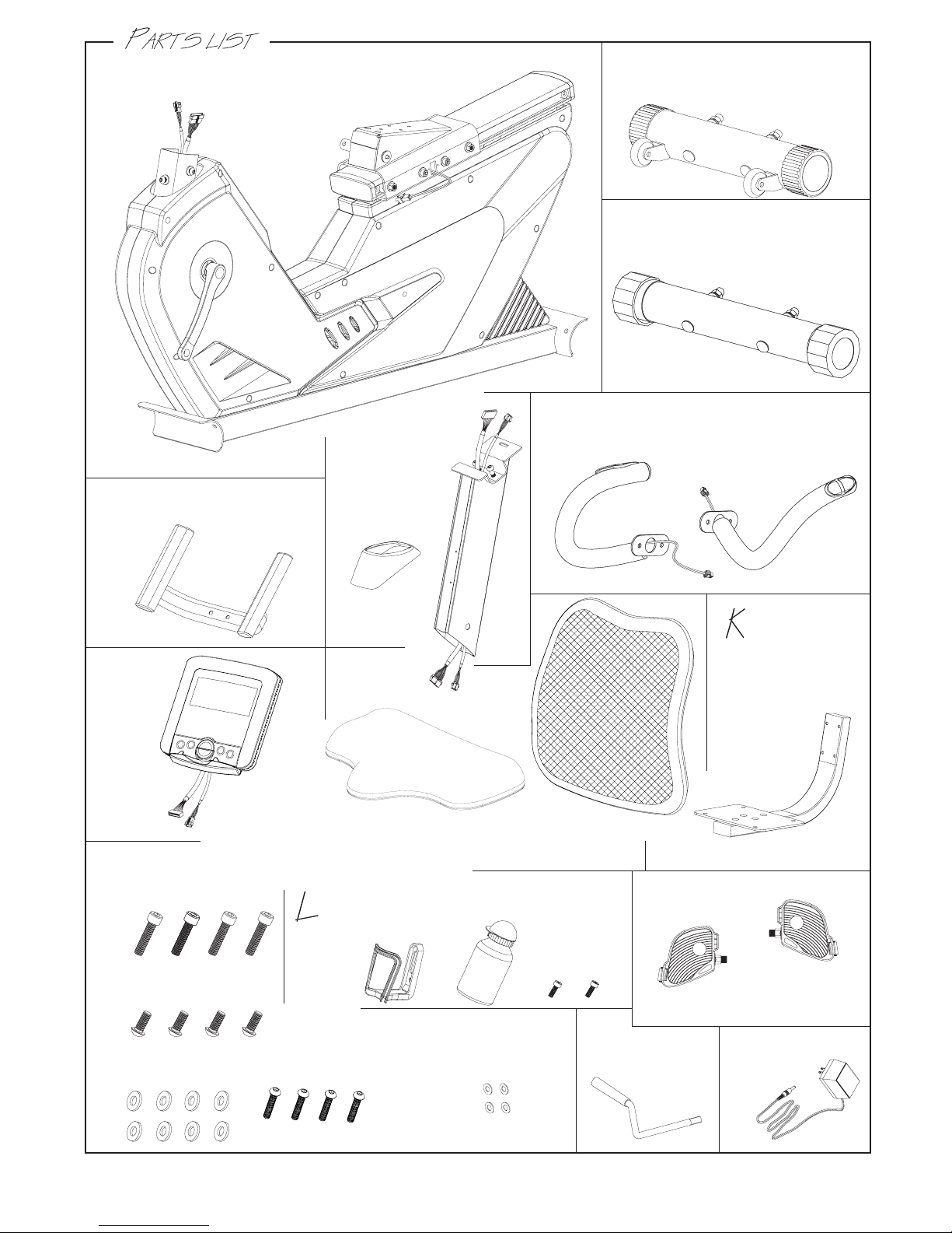
950RB Parts List
Parts No. Description Qty. Parts No. Description Qty.
A1 Main Frame 1 A12 Driving Pulley 1
OM Owners Manual 1 A12-1 Speed Magnet 1
4tuN2-21A6wercS1-1A
A1-2 Screw 4 A12-3 Spring Washer 4
A1-3 Servo Motor 1 A12-4 Spring Washer 4
A1-4 Axle Bearings 2 A12-5 Screw 4
A1-5 Tension Cable 1 A12-6 Speed Sensor 1
A2 Belt Tension Wheel 1 A12-7 Speed Sensor Holder 1
A3 Sensor box 1 A13 Drive Axle 1
A4 Screw 2 A14 Front Chain Cover (L) 1
A4-1 Stop Bar Tube 1 A14-1 Cover Screws 7
A4-2 Stop Bar Shaft 1 A15 Front Chain Cover (R 1
A4-3 Stopper 1 A16 Rear Chain Cover (R 1
A4-4 Washer 1 A17 Rear Chain Cover (L) 1
A4-5 Nut 1 A17-1 Rear Cover Screws 8
A5 Seat Rail Bracket 1 B1 Front Stabilizer Bar 1
A5-1 Bolt 4 B2 End Cap 2
A5-2 Washer 4 B3 Bolt 2
A5-3 End Cap 1 B4 Washer 2
2tuN5B1paCdnE4-5A
A5-5 Screw Cover 4 B6 Transport Wheel 2
A5-6 Screw 4 B7 Screw 2
2tuN8B8rehsaW7-5A
A5-8 Seat Wheels 4 C1 Rear Stabilizer Bar 1
A5-9 Metal Bushing 4 C2 End Cap Rear 2
A5-10 Nut 4 C3 Bolt 2
A5-11 Washer 2 C4 Washer 2
2tuN5C2gnihsuB21-5A
A5-13 Steel Strap 2 D Small Handle Bar 1
A6 Aluminum Track 1 D1 End Cap 4
A6-1 Screw 4 E1 Central Support Tube 1
A6-2 Bushing 4 E1-1 Aluminum Strap 1
A8 Hand Pulse Wire 2 E3 Computer Wire 1
A9 Bolt 3 E4 Heart Rate Wire 1
A10 Poly V Drive Belt 1 E5 Bolt 2
A11 Magnetic Flywheel 1 E6 Washer 2
A11-2 Nut 2 F1 Right Side Handle Bar 1
5
950RB Parts List
Parts No. Description Qty. Parts No. Description Qty.
A11-3 Bushing 2 F1-1 Handle Bar sponge 1
F1-2 Hand Pulse Sensor 1 K1 Rear End Cap 1
F2 Left Side Handle Bar 1 L1 Bottle Holder 1
F2-1 Handle Bar Sponge 1 L2 Water Bottle 1
F3 Hand Pulse Sensor 1 L3 Screw M5x18mm 2
G Computer Console 1 M1 Left Pedal 1
G2 Screw 2 M1-1 Crank Arm Left 1
G3 Dc wire 1 M1-2 Nut 1
H1 Seat pad 1 M1-3 Bolt Cover 1
H2 Back Pad 1 M2 Right Pedal 1
J1 Screw M8x35mm 4 M2-1 Crank Arm Right 1
J2 Bolt 4 M2-2 Nut 1
J3 Washer M8 8 M2-3 Bolt Cover 1
J4 Bolt 4 N AC Adaptor 1
J5 Washers 4 N-1 Rear AC Inlet Plug 1
K2 Saddle End Cap 1
Assembly Tips
The LifeCore 950RB is made from the best materials and has been tested and received a
quality control review prior to its packaging to ensure the correct parts and proper fitting of
each component. This machine wa s designed to limit the amount of assembly needed by a
customer.
Before assembly of your product, distinguish a proper and appropriate location for the unit
where there is easy access to an electrical outlet with a surge protector. Unpack the box in a
clear work area to allow smooth assembly. Remove all the parts from the packing material;
however, do not discard packing material until assembly is complete. Double check
packing materials to make sure no parts were left behind.
Note that some hardware may be preassembled to components to help with assembly and
tools have been provided to assist with assembly.
Tools Required:
13 mm wrench
15 mm wrench
Philips Screw driver
6mm Allen wrench
5mm Allen wrench
4mm Allen wrench
6
Seat & Back Pad
*
Stop Bar
R
Adapter
0
/
Maim frame
#
Side handle bar
(
Rear stabilizer
E
Front stabilizer
$
Central
(E1)
'
support
tube
Small handle bar
&
Computer
)
(H2)Back pad
(H1)Seat pad
(E2)
Decoration
cover
(F2)Left
Saddle
Tube
(F1)Right
,
(J1) Bolt M8X35mm
(J2) Bolt M8X15mm
(J3) Washer M8
Pedal
(M1)-Left
(M2)-Right
(L1) Bottle holder
(L2)Water bottle
(L3)
Screw
M5X18mm
(J4) Bolt 1/4"X1-1/2" (J5) Washer M6
 Loading...