

LifeCore Fitness LC-1050UBs User's Product Manual

User’s Product Manual
LifeCore LC-1050UBs Upright Bike
Page | 1
Introduction
Congratulations on your purchase of the 1050UBs Upright Bike. This product has been designed
and manufactured to meet the needs and requirements of domestic use.
By Choosing your 1050UBs Upright Bike, you have made a wise decision that will improve the
health of you and your family. Being fit and healthy will improve your energy level and your quality of
life.
Cardiovascular training is vital for all ages and the 1050UBs Upright Bike provides a more effective
workout, producing better results, and will encourage you to reach your fitness goals and maintain
the body you have always wanted.
In order to make your experience with LifeCore the best it can be, please review the enclosed user’s
manual prior to assembly and first use. Be sure to keep the instructions for reference and/or
maintenance.
We also offer a complete line of fitness equipment; please take a moment to review our other
excellent products at www.lifecorefitness.com. Should you have any questions, please contact us.
Your feedback and ideas about your experience with LifeCore are also very important to us. Write to
us at:
LifeCore Fitness Inc.
2575 Pioneer Ave. Suite 101
Vista, CA 92081
We wish you lots of success and fun while training!
Purchaser’s Reference Information
Serial Number is located on the frame
Please send in the attached warranty card and a copy of the original receipt or register online
at www.lifecorefitness.com within (10) days of purchase to register your product with
LifeCore Fitness.

Page | 2
Table of Contents
Introduction…………………………………………………………………………………….............
Purchaser’s Reference Information ………………………………………………………………….
Table of Contents………………………………………………………………………………………
Safety instructions and Warnings…………………………………………………………………….
Assembly Instructions …………………………………………………………………………………
How to Adjust the Handle Bar & Saddle Position ………………………………………………….
How to Transport the Bike ……………………………………………………………………………
Console Operation Instructions ………………………………………………………………………
Monitoring Your Heart Rate ………………………………………………………………………….
Heart Rate Monitoring Devices ………………………………………………………………………
Care and Maintenance ……………………………………………………………………………….
Warranty Card………………………………………………………………………………………….
1
1
2
3
4
11
11
12
19
21
22
23

Page | 3
Safety Instructions & Warnings
The 1050UBs Upright Bike is designed and manufactured to meet or exceed all domestic and
international safety standards. However, certain precautions need to be followed when operating any
exercise equipment.
General safety instructions:
1. It is important to consult your physician before any exercise program.
2. Pregnant women should consult with their physician before beginning any exercise program.
He/she can help determine the exercise program that is the most appropriate for your age and
physical condition.
3. If you experience dizziness, nausea, chest pains or other abnormal symptoms during exercise,
stop the exercise session immediately. Consult your physician before continuing your exercise.
4. Keep children away from the equipment. Hands and feet may get caught in the pedals or other
moving parts, which could result in serious injury.
5. No more than one person should ever use the product at a time.
6. Pets should never be allowed near unit.
7. Always wear proper clothing and shoes when exercising. Drink plenty of fluids when exercising.
8. Always stretch and warm up before starting any exercise program.
9. Never operate this unit if it is damaged or broken. Contact your authorized dealer for service.
10. Place your equipment on a solid, level surface when in use.
11. Place your unit in an area with enough clearance to operate the equipment.
12. Make sure all components are fastened securely at all times.
Product safety instructions:
1. Start your exercise program gradually. Exercise only for a few minutes the first day to let your
body adjust to the new exercise.
2. Slowly increase your exercise time and intensity over the first two weeks. If you increase your
intensity too rapidly, or fail to warm up properly, you can increase the risk of injury.
3. Use of this machine with worn or weakened parts, may result in injury to the user. We strongly
suggest replacing it immediately. Use only the accessory attachments recommended by the
manufacturer.
4. Unit maximum weight limit is 300LBS
5. It is recommended the unit be plugged into a surge protector. Do not place machine in an area of
high voltage or electromagnetic fields.
6. Whenever mounting or dismounting from the exercise machine, make sure that the unit is not in
motion and use caution to prevent injury. Use the handlebars or a helper whenever additional
stability is required.
7. Make sure that all components are fastened securely including but not limited to seat, pedals,
handlebars, or any electric components.
8. Never place any open containers of any type directly on the unit, only containers with lids are
recommended to be used with the appropriate water bottle holder.
9. Keep machine clear of any obstructions, heavy machinery, and never place objects on or against
machine. Perform proper maintenance as recommended in this manual.
10. Failure to follow these instructions will void the units warranty and the manufacturer or distributor
assumes no responsibility for personal injury or property damages related to the product if unit is
ever used incorrectly or for reasons other than exercise.
11. Save this manual for future reference.
Page | 4
Assembly Instructions
The LifeCore 1050UBs Upright Bike is made from the best materials and has been tested and
received a quality control review prior to its packaging to ensure the correct parts and proper fitting
of each component.
Before assembly of your product, distinguish a proper and appropriate location for the unit where
there is easy access to an electrical outlet with a surge protector. Unpack the box in a clear work
area to allow smooth assembly. Remove all of the parts from the packing material; however, do not
discard packing material until assembly is complete. Double check packing materials to ensure no
missing parts were left behind.
Note that some hardware may be preassembled to components in order to help with assembly; tools
have also been provided to assist with assembly. If you are missing any parts, assembly bags or
need assistance with assembly please call LifeCore Fitness at 1-888-815-5559.
Below are step by step assembly instructions:
Tool Needed:
6mm Allen wrench
13mm & 15mm wrench
Screw driver
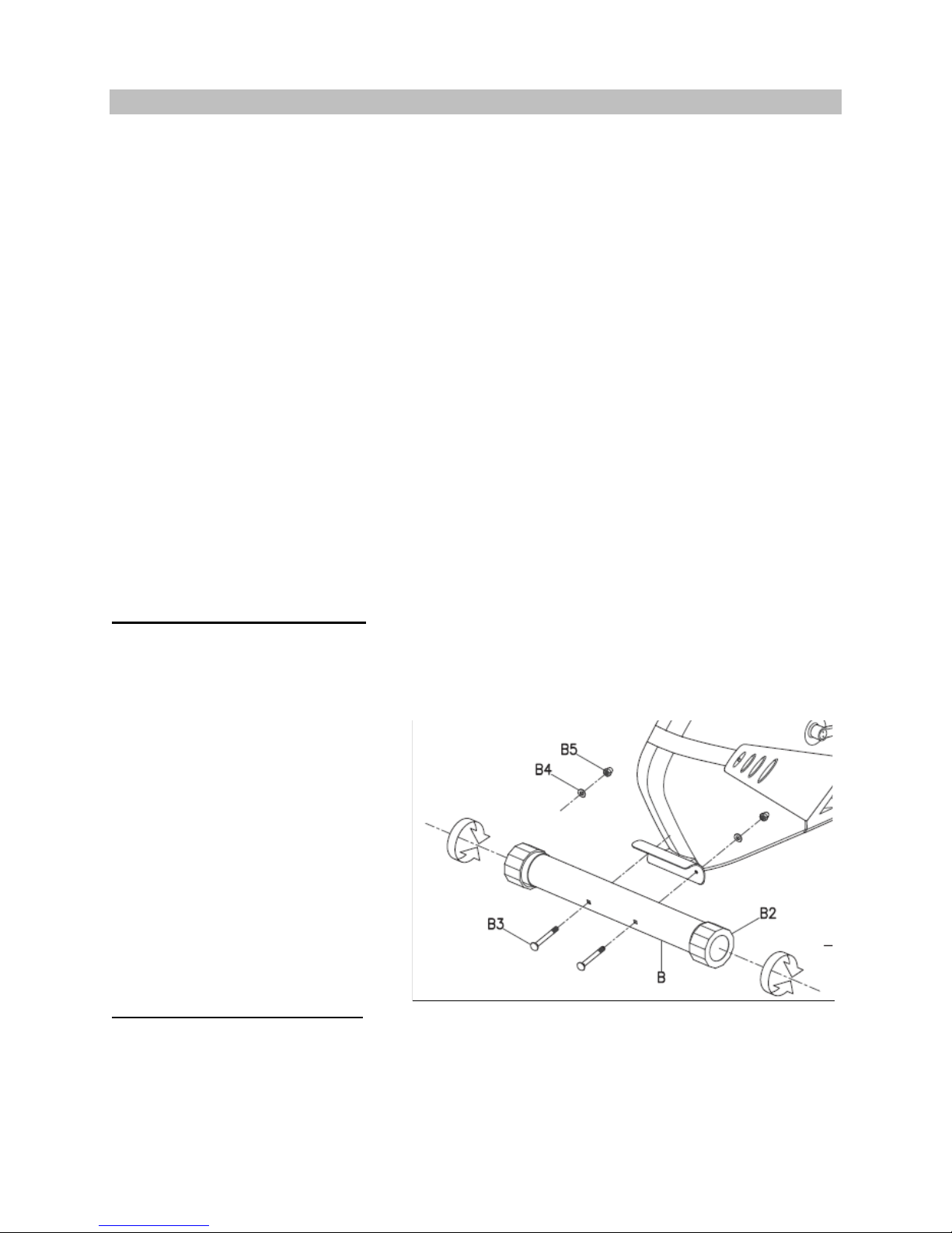
Step 1: Rear Stabilizer Assembly
Tool Needed:
13mm wrench
1) Remove pre-assembled bolts (B3),
washers (B4) and nuts (B5) from
the rear stabilizer (B).
Note: Apply blue loctite to the threads
of each bolt before attaching. The
loctite is located in the user’s manual
packet.
2) Attach the rear stabilizer (B) to the
main frame with same bolts,
washers and nuts. Use a 13mm
wrench or the tool that comes with
the machine to tighten nuts.
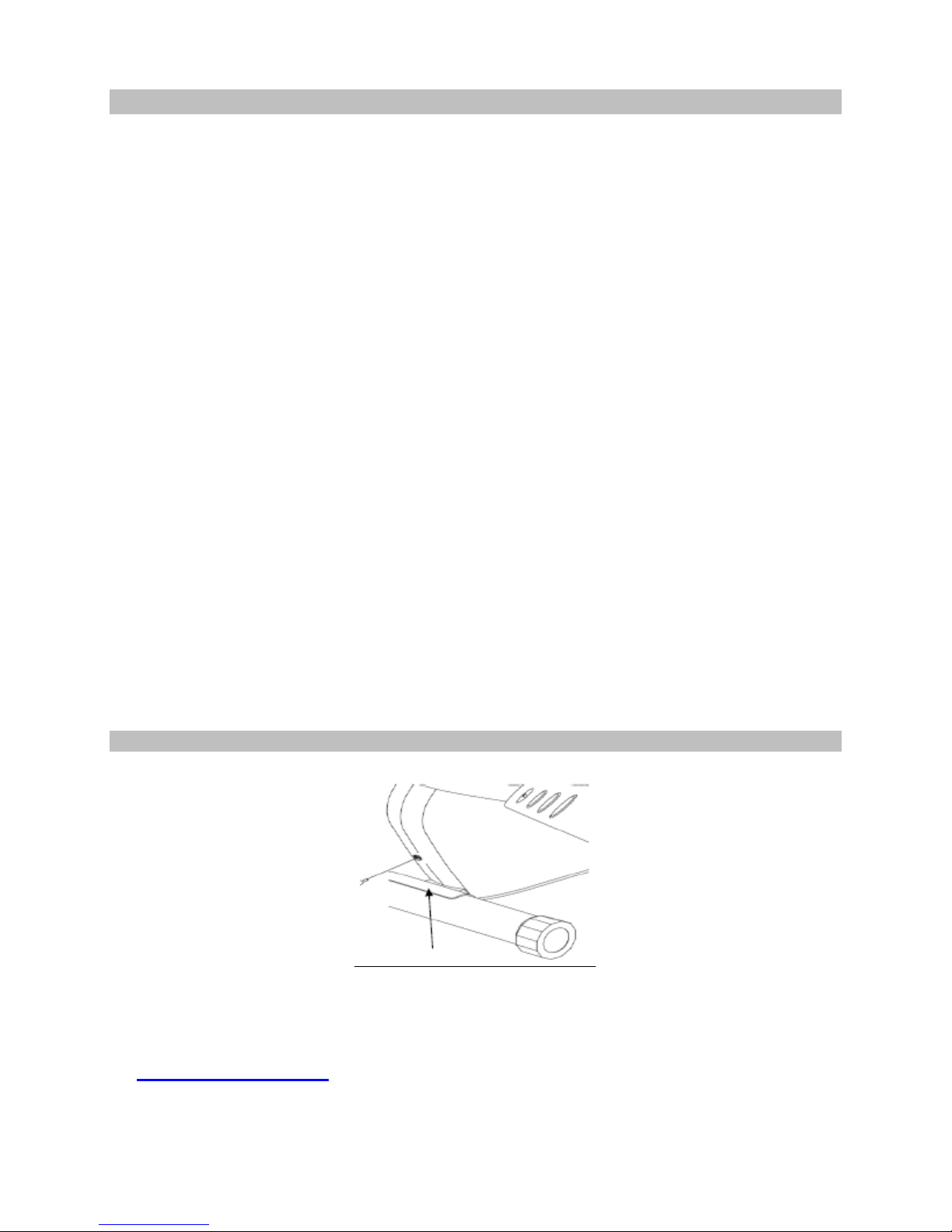
How to Keep the Machine Stable
Note: After the stabilizers are attached
in (Step 1 & Step 2), check to see if
the machine is stable. If the machine is
unstable, then adjust the rear end
caps (B2) to level the machine.
Figure 1
Page | 5
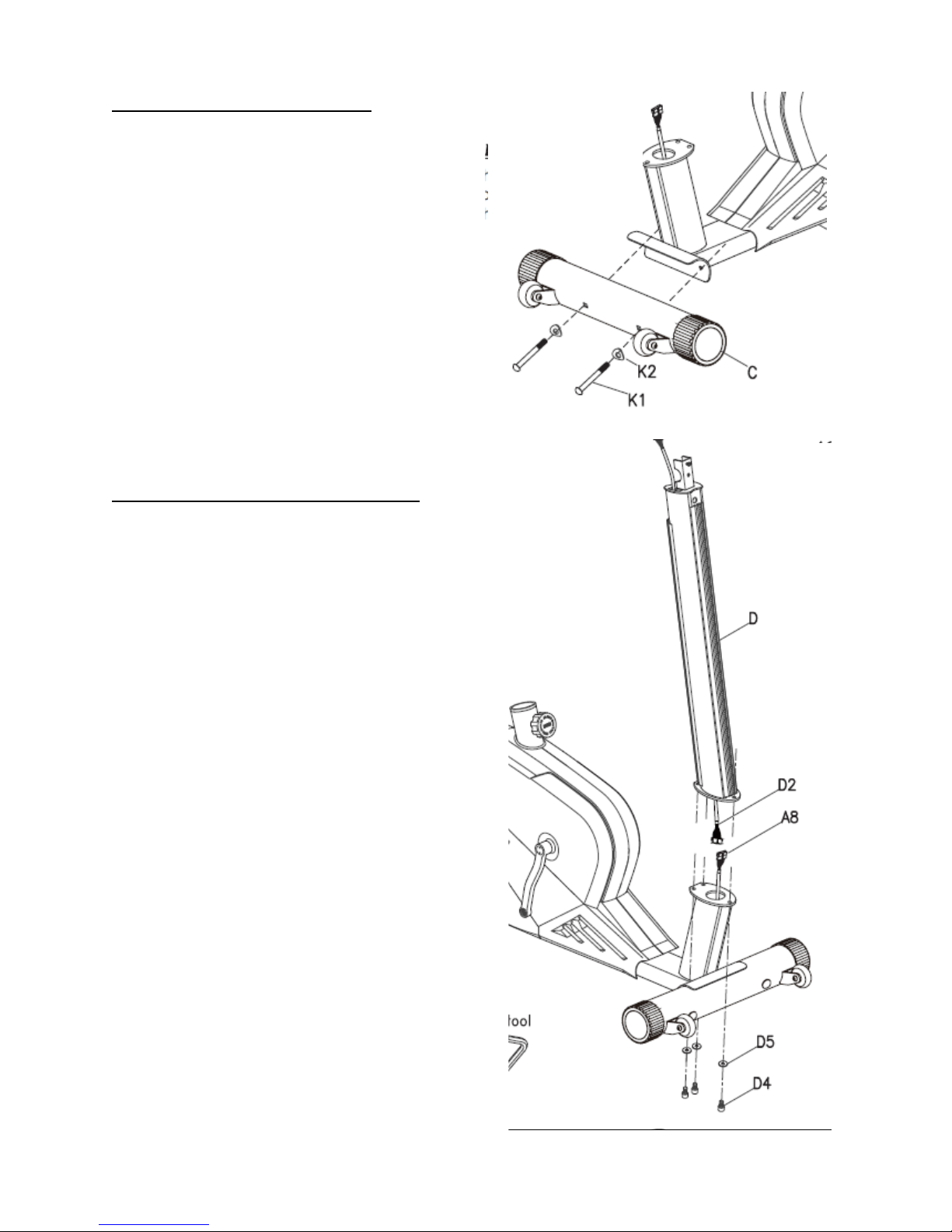
Step 2: Front Stabilizer Assembly
Tool Needed:
6mm Allen wrench
Note: Apply blue loctite to the threads of
each bolt.
(See Figure 2) Attach the front stabilizer (C)
to the main frame with bolts (K1) and
washers (K2), using a 6mm Allen wrench to
tighten them.
Step 3: Central Support Tube Assembly
Tool Needed:
6mm Allen wrench
Note: Additional assembly help maybe
needed.
1) Remove bolts (D4) and washers (D5)
from the central support tube (D).
2) (See Figure 3) Locate and connect
cable (D2) with cable (A8) together,
make sure connections are joined
properly.
Note: Be careful not to pinch wires while
joining the two parts.
3) Apply blue loctite to the threads of each
bolt.
4) Place the central support tube (D) on the
main frame and secure it with bolts (D4)
and washers (D5) to tighten the central
support tube. Use a 6mm Allen wrench
to tighten them.
Figure 2
Figure 3

Page | 6
Step 4: Central Support Tube Cover Assembly
Tool Needed:
Screw driver
(See Figure 4) Connect the decoration covers (K6-L & K7-R) to the front of the main frame.
Using a screw driver, tighten screws (K3) to secure covers together.
Step 5: Front Handle Bar Assembly
Tool Needed:
13mm wrench
Note: Additional assembly help maybe needed.
1) Remove the nut (E9) and washer (E8) from the handle bar.
2) (See Figure 5) Joint the hand bar assembly to the central support tube using the same
washer and nut; using a 13mm wrench to tighten them.
Figure 4
Figure 5
Page | 7
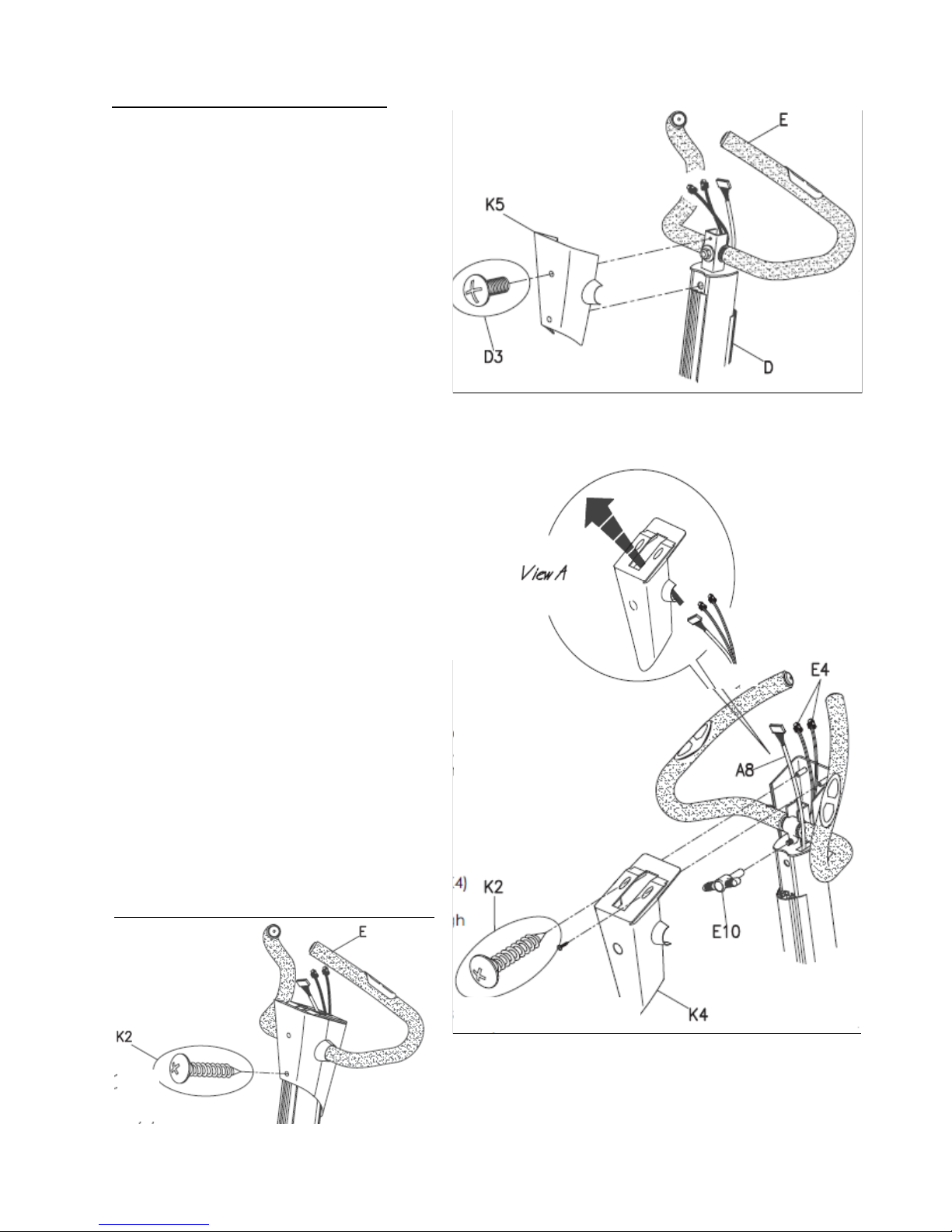
Step 6: Console Housing Assembly
Tool Needed:
Philips screw driver
(See Figure 6-1) Console Rear Housing
1) Remove the pre-installed screw (D3)
and connect the housing cover (K5) to
the central support tube (D).
2) Use a screw driver to tighten the cover
into frame with screw (D3).
(See Figure 6-2) Console Front Housing
1) Remove knob (E10) from the handle bar
assembly. Locate the house cover (K4)
and connect it to the central support
tube. Make sure wires (A8 & A4) are
feeding through the top of cover (see
View A).
Note: Be careful not to pinch wires.
2) Join the two covers together. Using a
screw driver and tighten these two
covers with screws (K2).
3) Retighten the knob (E10) to the handle
bar assembly.
4) Make sure all wires are outside the
housing covers. Locate one screw (K2)
and finish screwing the two covers
together. See figure below.
Figure 6-1
Figure 6-2
Page | 8
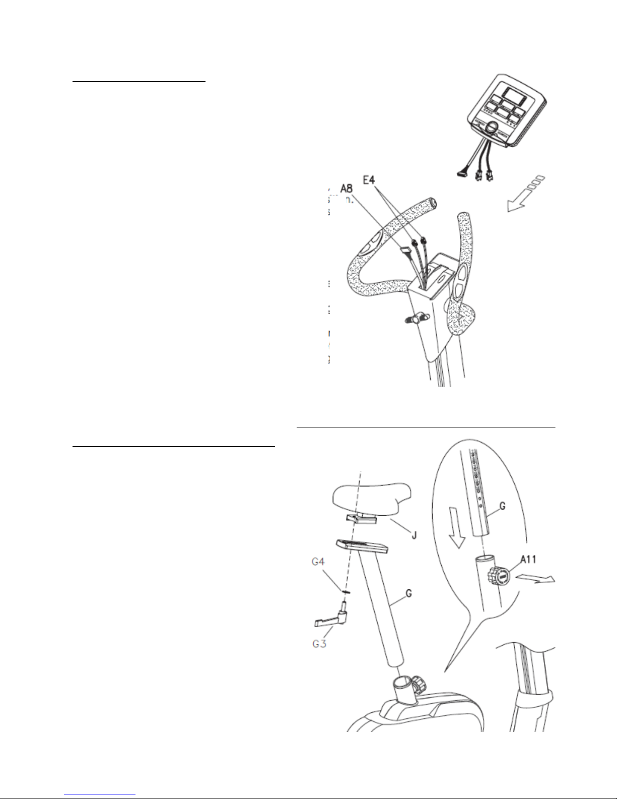
Step 7: Console Assembly
1) (See Figure 7) Connect console wire
(A8) and heart rate wires (E4) to the
console. Make sure that the wires are
connected together properly.
2) Slide the console onto the housing
covers. Be careful not to pinch the wires
while sliding the console. Push and
store excess wires back into housing
covers.
Step 8: Saddle & Saddle Tube Assembly
1) Remove knob (G3) and washer (G4)
from saddle (J).
2) Position saddle onto the moving
basement and tighten it using washer
(G4) and knob (G3).
3) Loosen knob (A11) on the saddle tube’s
receiver and pull on the knob to slide the
saddle tube (G) onto receiver. Once it is
locked in place, release the knob to
secure the saddle tube.
Figure 7
Figure 8
 Loading...