

Page 1
Installation
Instructions
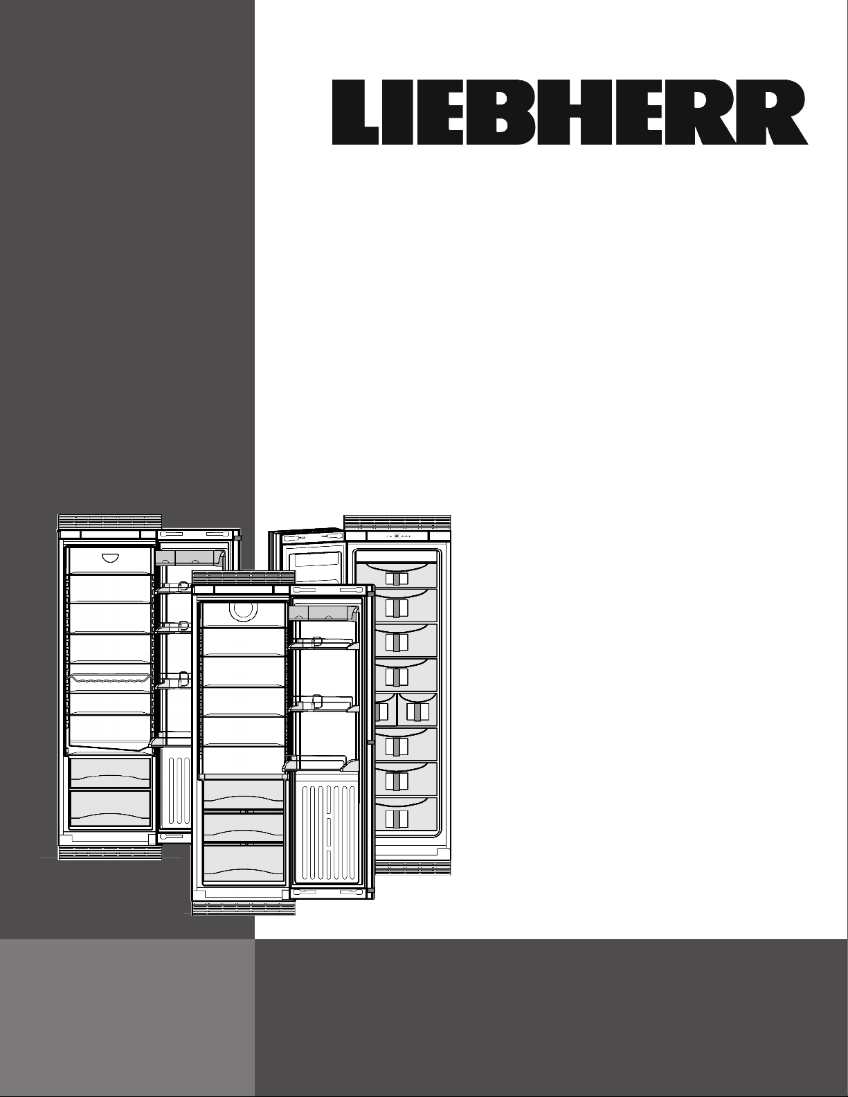
Refrigerators and freezers, built-in
R 1410/ RB 1410/ F 1051
280815 7084602 - 02
Page 2
General safety information
Contents
1 General safety information........................... 2
2 Setting up the appliance............................... 2
3 Planning information..................................... 4
4 Cabinet Opening Dimensions...................... 7
5 Air circulation in the kitchen cabinet........... 7
6 Door swing clearance................................... 8
7 Changing the door hinges............................ 13
7.1 Remove soft stop mechanism (top).................. 13
7.2 Remove soft stop unit (bottom)........................ 13
7.3 Remove door................................................... 14
7.4 Swapping bearing parts................................... 14
7.5 Swapping the handle........................................ 15
7.6 Fitting the door................................................. 15
7.7 Fitting the soft stop mechanism (bottom)......... 15
7.8 Fitting soft stop mechanism (top)..................... 16
7.9 Aligning the door.............................................. 16
8 Water connection........................................... 16
9 Anti-tip device................................................ 17
10 Single unit installation.................................. 17
11 Side-by-side installation............................... 20
12 Adjusting the door opening angle............... 24
13 Installing the water filter............................... 25
14 Connecting the appliance............................. 26
The manufacturer is constantly working to improve all
models. Therefore please understand that we reserve the
right to make design, equipment and technical modifications.
To get to know all the benefits of your new appliance,
please read the information contained in these instructions carefully.
The instructions apply to several models, so there may be
differences. Sections which only apply to certain appliances are indicated with an asterisk (*).
Instructions for action are marked with a
results of action are marked with a .
, the
-
The socket must be easily accessible so that
the appliance can be disconnected from the
mains quickly in an emergency. It must not be
behind the back of the appliance.
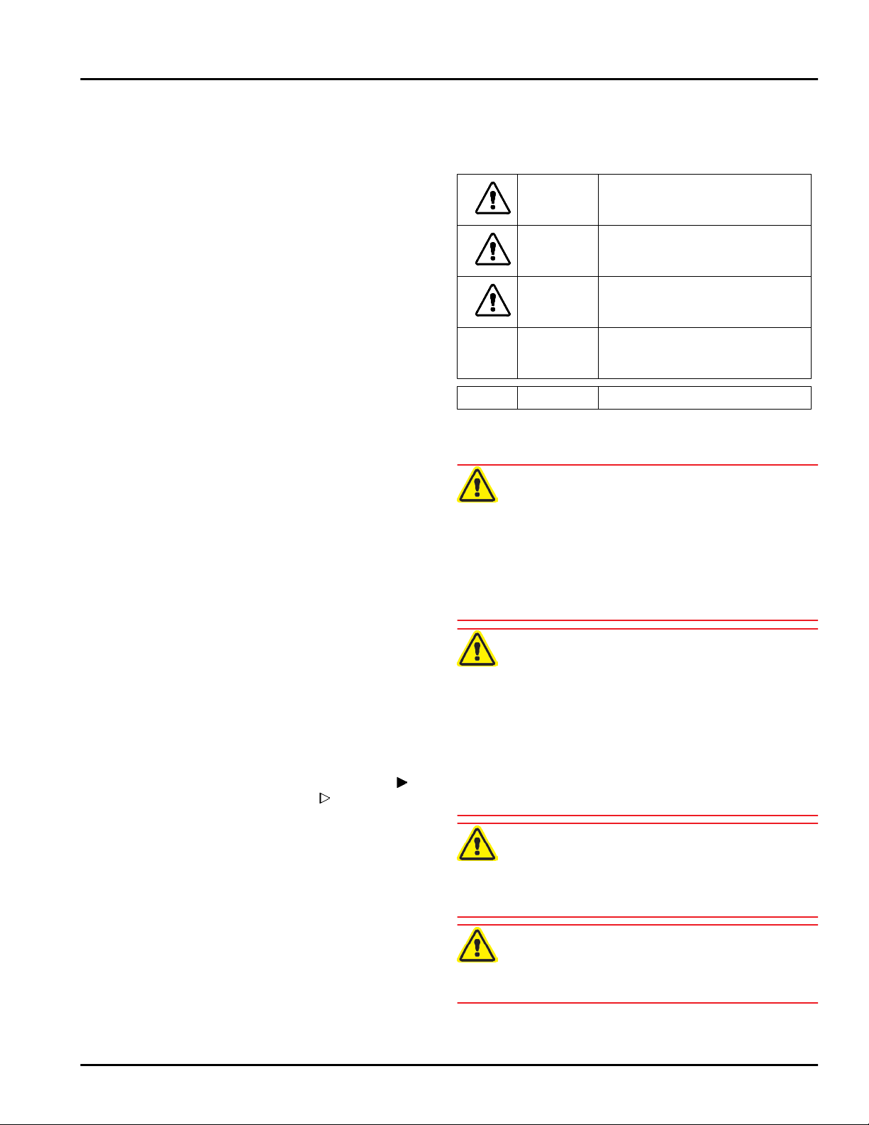
DANGER indicates a hazardous situation,
which if not avoided, will result in
death or serious injury.
WARNING indicates a hazardous situation,
which if not avoided, could result in
death or serious injury.
CAUTION indicates a hazardous situation,
which if not avoided, will result in
minor or moderate injury.
NOTICE indicates a hazardous situation,
which if not avoided, could result in
damage to property.
Note indicates useful advice and tips.
2 Setting up the appliance
WARNING
Risk of fire due to moisture!
If live parts or the power cord get wet, this can cause a
short circuit.
The appliance is designed for use in enclosed spaces.
u
Do not operate the appliance in open space or in damp
areas or where there is spray.
Only operate the appliance after it has been installed.
u
WARNING
Risk of fire due to short circuit.
If the power cable or plug of the appliance or another
appliance and the back of the appliance touch each other
the power cable or plug will be damaged by the vibrations
of the appliance which could lead to a short circuit.
Install the appliance so that it does not touch any plugs
u
or power cables.
Do not connect the appliance or other appliances to the
u
sockets on the back of the appliance.
1 General safety information
-
Read and follow these instructions. They
contain safety advice which is important for
Danger of fire and damage!
u
safe and problem-free installation and operation. Always read and follow the safety advice.
-
It is important that the guidelines and instructions in this manual are followed so that the
appliance is correctly installed and operates
properly Read and understand all information
Risk of personal injury!
u
in this manual before the appliance is installed
2 * Depending on model and options
WARNING
Do not place devices that give off heat, e.g. microwaves, toasters, etc. on the appliance.
CAUTION
Have two people move this appliance into place.
Page 3
NOTICE
Risk of damage caused by condensation
Installing the appliance next to any other refrigerator or
freezer can cause condensation or damage to the Liebherr appliance.
Do not install this appliance next to any other refriger-
u
ator or freezer except another Liebherr model. Liebherr
models are designed to allow side-by-side installation.
They are equipped with a heating system to eliminate
condensation when refrigerators or freezers are
installed side-by-side.
NOTICE
Risk of damage for the finished floor surface!
Protect the finished floor surface before you uncrate the
u
unit.
Verify that:
The floor under the appliance is flat and level.
q
The floor can support the appliance's weight plus
q
approximately 1200 pounds (544 kg) of food weight.
The appliance is not placed in direct sunlight or near
q
the stove, range top, radiators and similar heat
sources.
The kitchen cabinet that the appliance is installed in is
q
shimmed to the floor level if the floor heights are not
equal.
Setting up the appliance
Cutout dimensions are accurate.
q
Electrical outlet is in correct location.
q
The air flow is not restricted. Air flow must be provided
q
for the appliance to operate properly. The factory air
vents provide 31 square inches (200 cm2) of air flow
per appliance. If you are replacing the air vents with an
overlay, the air flow must be the same or greater than
the factory air vents.
Examine the unit and packaging for shipping damage.
u
Contact the carrier immediately if you suspect there is
any damage.
Note the type (model, number), index, appliance/serial
u
number, date of purchase and where purchased .
Remove anything attached to the rear or side walls of
u
appliance that would prevent proper installation or
impede proper ventilation.
Remove the protective film from the outside of the
u
appliance.
Note
Clean the appliance .
u
If the appliance is set up in humid areas, condensation
may build on the outside of the appliance.
Always ensure proper ventilation.
u
Assemble appliances according to separate installation
u
instructions.
* Depending on model and options 3
Page 4
Planning information
3 Planning information
Fig. 1 Single-
unit installation
4 * Depending on model and options
Page 5
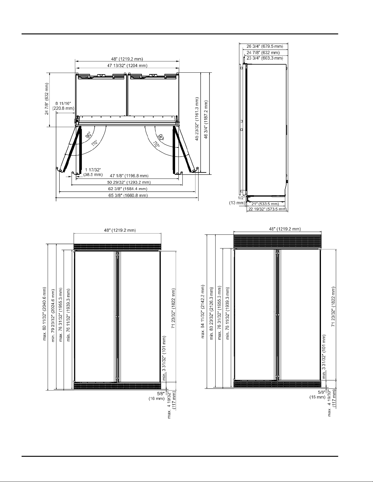
Planning information
Fig. 2 Side-by-side installation: SBS 241, SBS246, SBS 243
Fig. 3 Side-by-side installation: SBS 243 with 80” or 84” ventilation grille
* Depending on model and options 5
Page 6
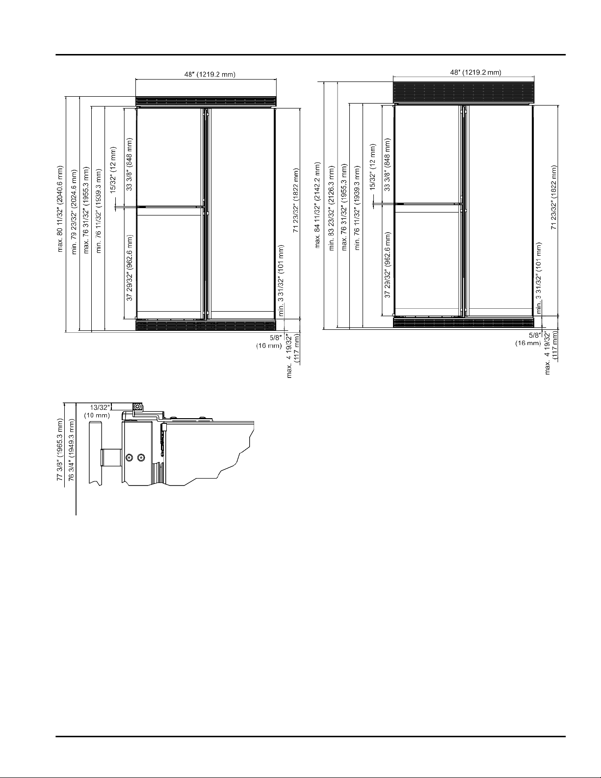
Planning information
Fig. 4 Side-by-side installation: SBS 246 and SBS 241 with 80” or 84” ventilation grille
Fig. 5 Side-by-side installation: without ventilation grille
6 * Depending on model and options
Page 7
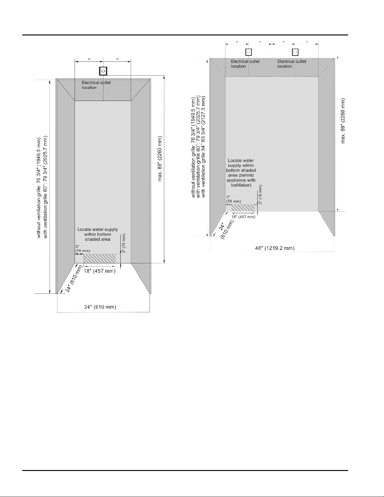
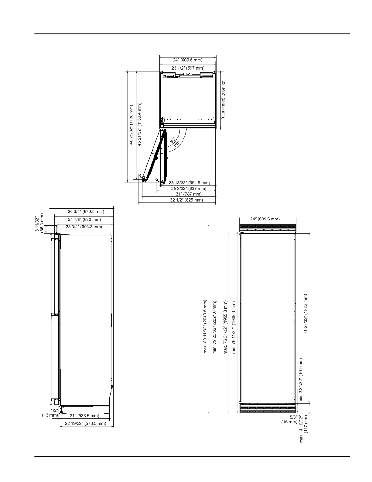
4 Cabinet Opening Dimensions
Cabinet Opening Dimensions
Fig. 6 Single installation
Fig. 7 Side-by-side installation:
The door must be able to be opened at least 90° to allow
the drawers to be pulled out properly. If the door opening
angle is 90° it may be difficult to remove the drawers due
to the door racks.
If the appliance will be installed in a corner please leave a
gap of at least 3-3/4 in. (95 mm) from the wall.
5 Air circulation in the kitchen cabinet
This is a built-in refrigerator-freezer with stainless steel
doors.
The unit is not intended for freestanding use and has to
be installed inside a cabinet. This type of cabinet must be
carefully constructed using the proper dimensions and it
must provide proper ventilation to ensure proper appliance operation.
* Depending on model and options 7
Page 8
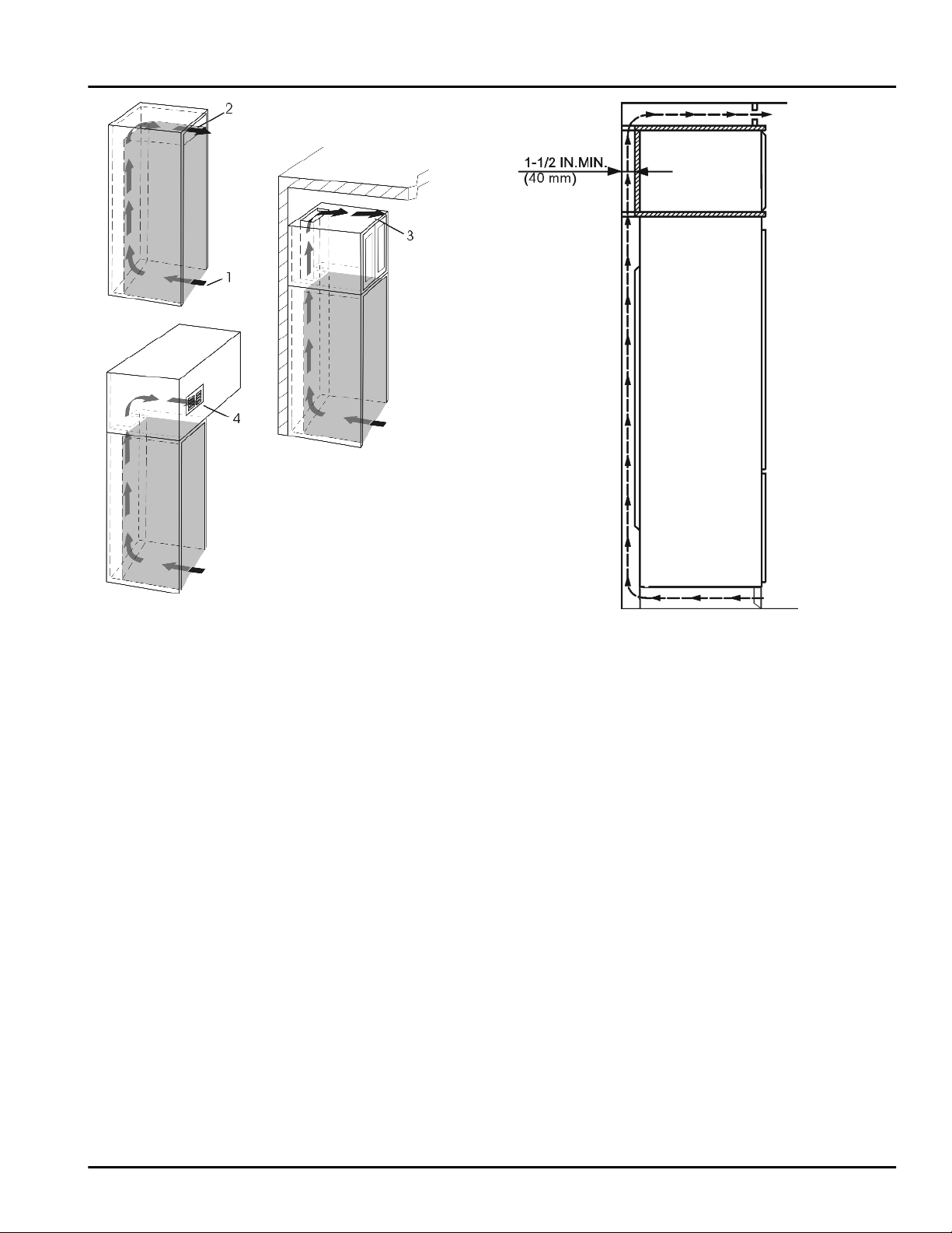
Door swing clearance
Fig. 8
-
An effective ventilation cross-section of at least 31 in
(200 cm2) per unit must be present at the air intake
Fig. 8 (1)
- The upper ventilation cross-section can be set up
directly above the appliance with an optional ventilation
grille
or as an air vent in an intermediate ceiling
and air outlet
Fig. 8 (2)
Fig. 8 (2)
, near the ceiling above a cabinet
.
Fig. 8 (4)
Fig. 8 (3)
.
2
- There must be an air shaft (unobstructed) with a
minimum depth of 1-1/2 in. (40 mm) behind the kitchen
cabinet.
The air-circulation clearances indicated above must be
u
maintained.
Fig. 9
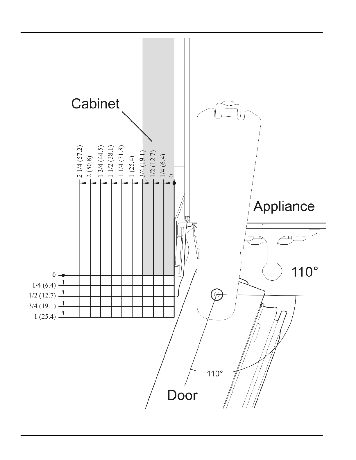
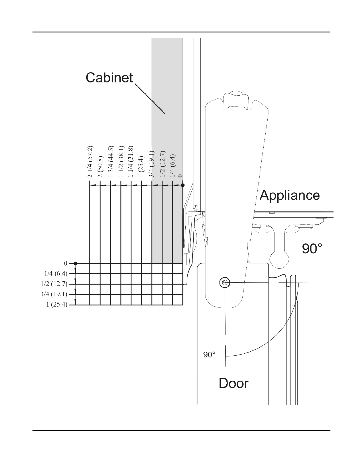
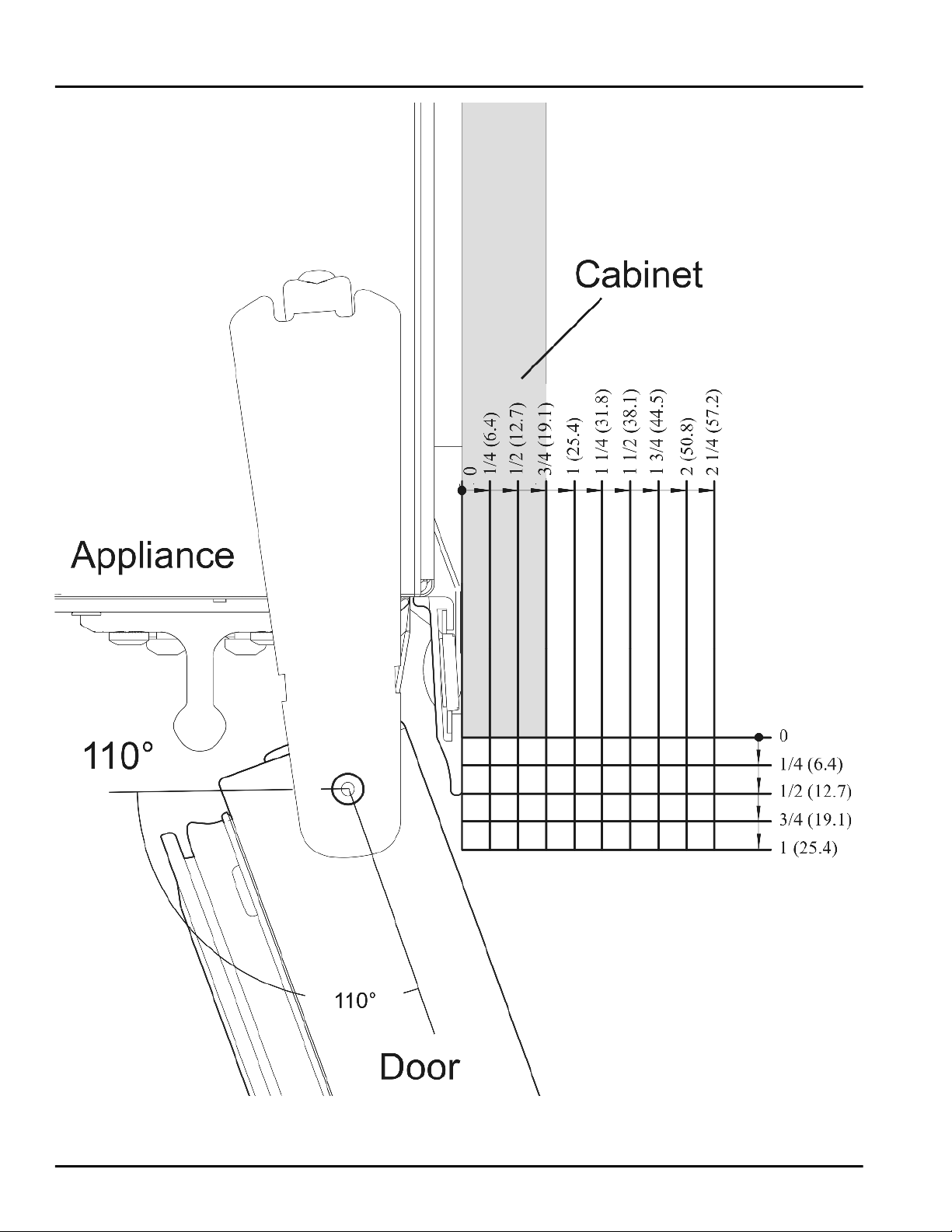
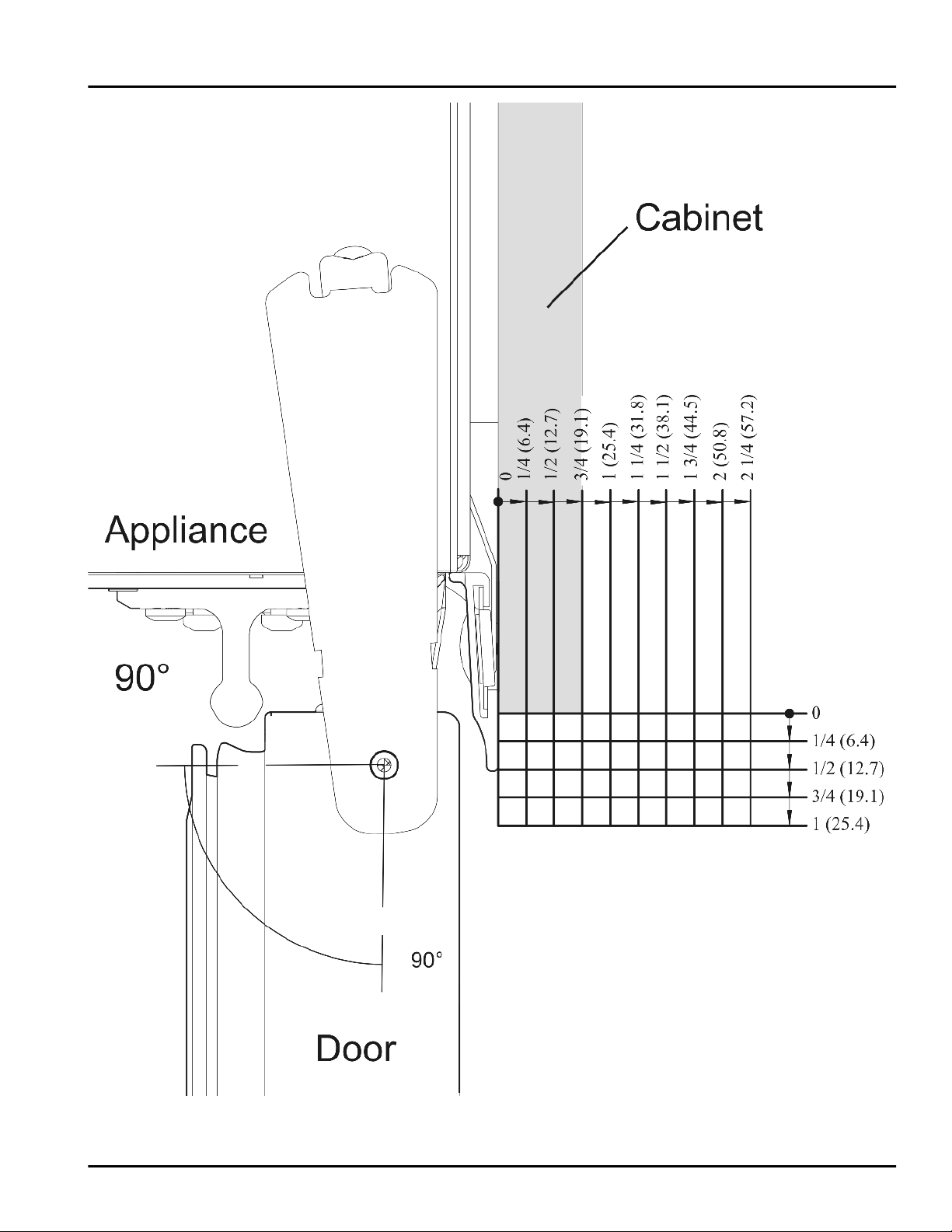
6 Door swing clearance
Frameless cabinets: The casing trim overlaps the cabinets at the side and top. Cabinets may require filler strips
to prevent interference with the cabinet door swing. The
door opening must allow for filler strips.
The factory setting for the door to swing open is 110°. The
optional setting for the door to swing open is 90°. Use the
following illustrations (1:1) to ensure other cabinets or
counters do not interfere with the door opening.
8 * Depending on model and options
Page 9
Door swing clearance
Fig. 10 110°, hinges on left
* Depending on model and options 9
Page 10
Door swing clearance
Fig. 11 90°, hinges on left
10 * Depending on model and options
Page 11
Door swing clearance
Fig. 12 110°, hinges on right
* Depending on model and options 11
Page 12
Door swing clearance
Fig. 13 90°, hinges on right
12 * Depending on model and options
Page 13
7 Changing the door hinges
You can reverse the door hinges, if necessary:
Make sure you have the following tools on hand:
Torx 25
q
Torx 15
q
Screwdriver
q
Cordless screwdriver, if necessary
q
Another person to help with the installation, if
q
necessary
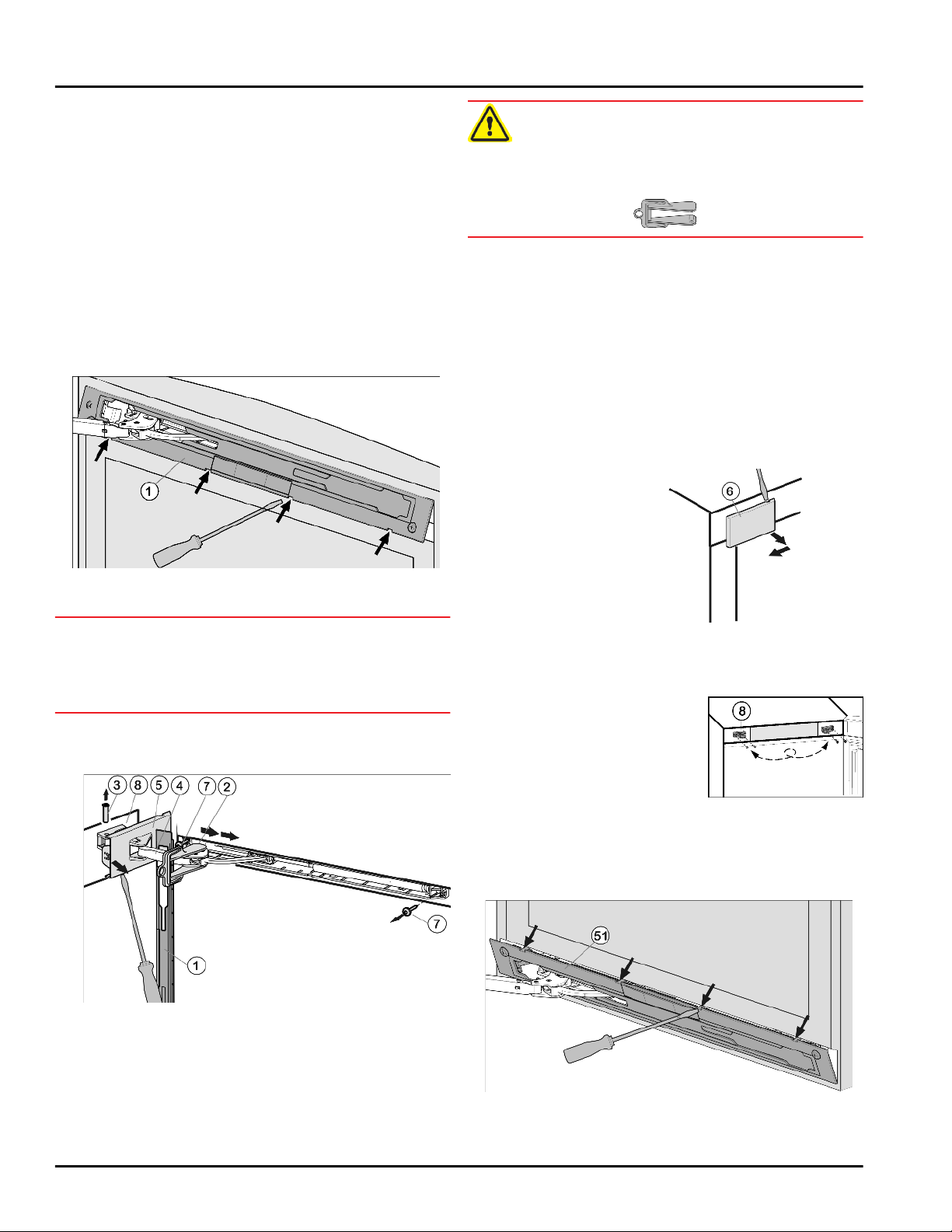
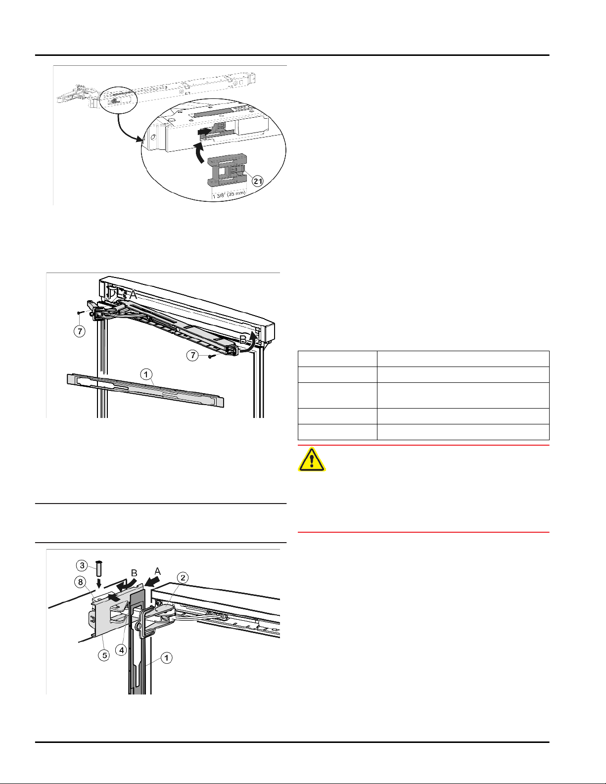
7.1 Remove soft stop mechanism (top)
Changing the door hinges
WARNING
Risk of injury if the soft stop mechanism contracts!
If the locking device is not fitted, the soft stop mechanism
contracts during disassembly and can jam your fingers.
u
Fit the locking device!
Engage locking device
u
oblong hole.
The locking device prevents the hinge from snapping
w
shut.
Unscrew cover that is on the hinge side
u
the first notch using a screwdriver.
The bolt will become visible.
w
Push bolt
u
Press damper bracket
u
door.
Completely loosen cover that is on the hinge side
u
Fig. 15 (5)
Remove panel
u
Loosen cover that is on
u
the hinge side
using a screwdriver and
remove by pulling
outwards.
Fig. 15 (3)
and remove.
Fig. 15 (1)
Fig. 16 (6)
Fig. 15 (2)
out from below.
Fig. 15 (4)
.
in the direction of the
into place inside
Fig. 15 (5)
until
Fig. 14
Open the door.
u
NOTICE
Risk of damage!
If the door seal is damaged the door may not close properly and the level of cooling is insufficient.
Do not damage the door seal with the screwdriver!
u
Release panel
u
remove.
The panel hangs above the damper bracket.
w
Push panel forward over the damper bracket
u
in the direction of the appliance.
Fig. 14 (1)
using slotted screwdriver and
Fig. 15
Fig. 15 (4)
Fig. 16
Unscrew soft stop unit (2 x Torx 15)
u
Slightly pull out soft stop unit, push it towards the
u
handle side and open it out.
Set soft stop unit to the side.
u
Unscrew bearing part
u
Fig. 17 (8)
move it to the opposite
side. Make preliminary
holes (optional) or use a
cordless screwdriver.
, turn it 180° and
Fig. 15 (7)
.
Fig. 17
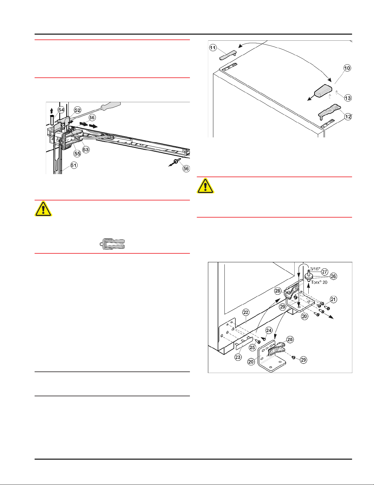
7.2 Remove soft stop unit (bottom)
Not for F 1051
Fig. 18
Open the door.
u
* Depending on model and options 13
Page 14
Changing the door hinges
NOTICE
Risk of damage!
If the door seal is damaged the door may not close properly and the level of cooling is insufficient.
Do not damage the door seal with the screwdriver!
u
Release panel
u
remove.
The panel hangs above the damper bracket.
w
Push panel forward over the damper bracket
u
in the direction of the appliance.
WARNING
Risk of injury if the soft stop mechanism contracts!
If the locking device is not fitted, the soft stop mechanism
contracts during disassembly and can jam your fingers.
u
Fit the locking device!
Engage locking device
u
oblong hole.
The locking device prevents the hinge from snapping
w
shut.
Lift off cover
u
driver and remove by pulling outwards.
Push bolt
u
Press damper bracket
u
door.
Remove panel
u
Unscrew entire soft stop unit (2 x Torx 15)
u
Slightly pull out soft stop unit, push it towards the
u
handle side and open it out.
Set soft stop unit to the side.
u
Fig. 18 (1)
Fig. 19 (52)
Fig. 19 (54)
Fig. 19 (51)
using slotted screwdriver and
Fig. 19 (55)
Fig. 19 (53)
from the outside using a screw-
out from below.
Fig. 19 (55)
.
into place inside
in the direction of the
Fig. 19 (56)
Fig. 19
.
Close the door.
u
Pull cover
u
remove.
Lift off cover
u
Risk of injury if the door tips out!
Keep a steady grip on the door.
u
Set the door down carefully.
u
Unscrew upper bearing bracket
u
Fig. 20 (13)
Lift the door upwards to remove and set it to the side.
u
Fig. 20 (10)
Fig. 20 (11)
CAUTION
and pull it upwards to remove.
forward and then upwards to
.
Fig. 20 (12)
(2 x Torx 25)
7.4 Swapping bearing parts
Fig. 20
7.3 Remove door
Note*
To prevent food items from falling out, take all food out
u
of the door racks before removing the door.
14 * Depending on model and options
Unscrew bearing bracket
u
bearing pin
doing so, hold panel
not drop.
Carefully lift off the cover on the handle side
u
and the plug
side.
Unscrew screw
u
side. When doing so, hold panel steady so that it does
not drop.
Fig. 21 (27)
Fig. 21 (24)
Fig. 21 (25)
Fig. 21 (20)
(3 x Torx 25)
Fig. 21 (22)
and move them to the opposite
steady so that it does
and move it to the opposite
together with
Fig. 21 (21)
Fig. 21
. When
Fig. 21 (23)
Page 15
Changing the door hinges
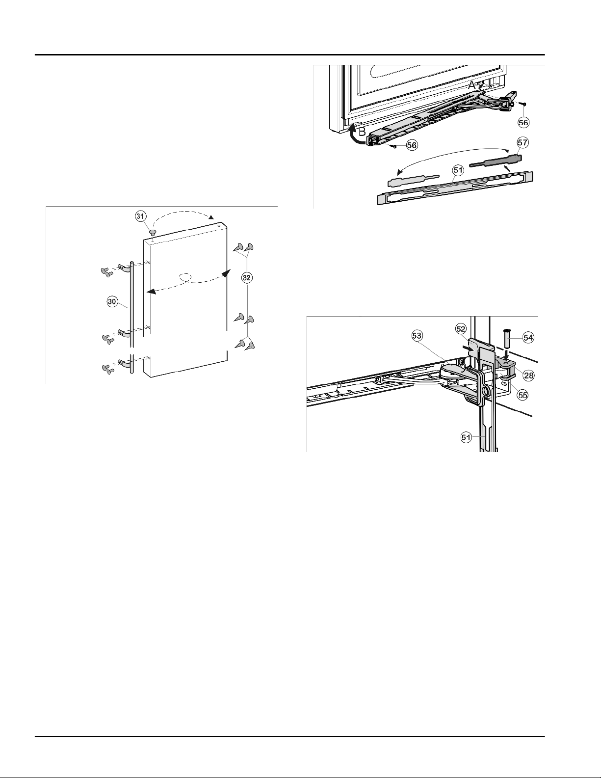
Unscrew bearing part
u
tighten
Fig. 21 (29)
Remove the bearing pin
u
side along with the bearing disc and bearing ring
Fig. 21 (26)
Using a cordless screwdriver if necessary, tightly
u
secure
new hinge side again by applying a screw torque of
3 lb-ft (4 Nm) . First fit the lower center screw, then the
other screws.
and secure tightly to 3 lb-ft (4 Nm) .
Fig. 21 (21)
Fig. 21 (28)
.
Fig. 21 (27)
the bearing bracket
, turn it 180° and
, move it to the other
Fig. 21 (20)
7.5 Swapping the handle
on the
Loosen cover
u
insert on the other side.
With the hinge of the soft stop unit facing the door
u
hinge side, engage the soft stop unit (A) and swivel
inwards (B).
The holes on the left and right must lie exactly above
w
each other.
Tighten soft stop unit (2 x Torx 15)
u
Fig. 23 (57)
from the panel
Fig. 23 (56)
Fig. 23 (51)
.
Fig. 23
and
Fig. 22
Pull plugs
u
and move them to the other side.
Detach the door handle
u
and move them to the opposite side.
Fig. 22 (31)
out of the door bearing bushes
Fig. 22 (30)
and plug
Fig. 22 (32)
7.6 Fitting the door
Ensure that the bearing discs
u
lower bearing pin
Position the door from above onto the bearing pins
u
below
Fig. 21 (27)
Close the door.
u
Insert the upper bearing bracket
u
hinge side into the door.
Secure the upper bearing bracket
u
applying a torque of 3 lb-ft (4 Nm) (2 x Torx 25)
Fig. 20 (13)
cordless screwdriver.
Snap both cover
u
place on the opposite side.
Fig. 21 (27)
.
. Make preliminary holes (optional) or use a
Fig. 20 (10)
Fig. 21 (26)
.
Fig. 20 (12)
Fig. 20 (12)
and cover
are on the
on the new
tightly by
Fig. 20 (11)
7.7 Fitting the soft stop mechanism (bottom)
Not for F 1051
into
Fig. 24
Hook panel
u
that the detent hooks are pointing forward and the front
side is facing the appliance.
Pull damper bracket
u
Fig. 24 (28)
that the square is resting in the recess.
Place cover
u
Check that the cover is positioned correctly such that
w
the door can close properly and the bolt is secured.
Remove locking device
u
Snap panel
u
Close the door.
u
Fig. 24 (51)
and insert bolt
Fig. 24 (52)
Fig. 24 (51)
into the damper bracket such
Fig. 24 (55)
on top and snap into place.
Fig. 24 (53)
into place on the door.
towards bearing part
Fig. 24 (54)
from above such
by twisting it.
* Depending on model and options 15
Page 16
Water connection
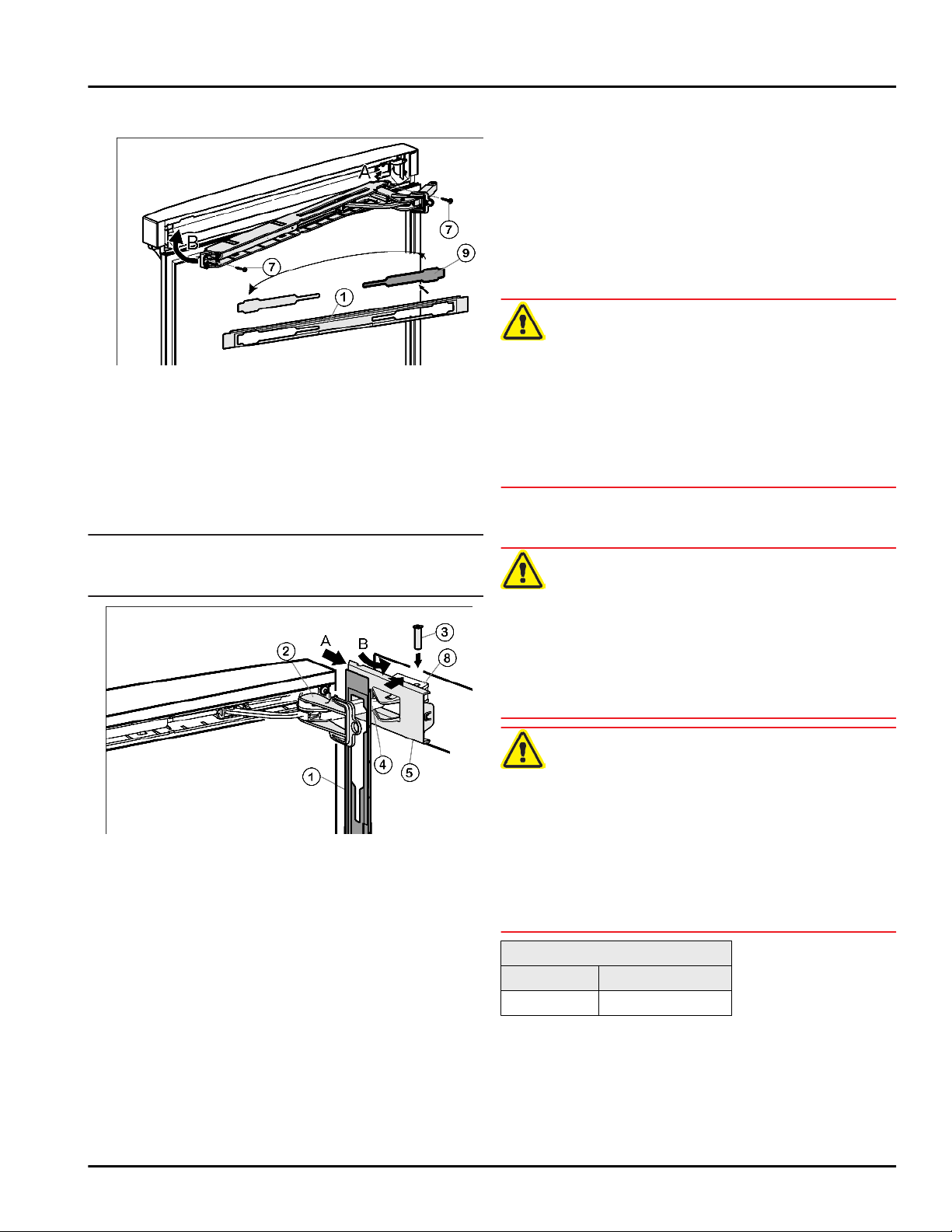
7.8 Fitting soft stop mechanism (top)
Fig. 25
Loosen cover
u
insert on the other side.
With the hinge of the upper soft stop unit facing the
u
door hinge side, engage the soft stop unit (A) and
swivel inwards (B).
The holes on the left and right must lie exactly above
w
each other.
Tighten soft stop unit (2 x Torx 15)
u
Note
Follow the correct sequence. First hang the panel over
u
the damper bracket, then the cover.
Fig. 25 (9)
from the panel
Fig. 25 (7)
Fig. 25 (1)
.
and
Snap panel
u
Turn cover
u
on top from the outside and snap into place.
Fig. 26 (1)
Fig. 16 (6)
into place on the door.
180° from the handle side, place it
7.9 Aligning the door
Unscrew center screw on lower part of bearing bracket
u
Fig. 21 (20)
Align the doors flush with the appliance housing using
u
the two oblong holes in the lower bearing bracket
Fig. 21 (20)
Risk of bodily injury due to the door falling off.
If the bearing parts are not installed with the proper
torque, the door may fall off. In addition, the door may not
close, thus impairing the cooling performance of the appliance.
Securely tighten the bearing brackets/bearing pins by
u
applying a torque of 3 lb-ft (4 Nm).
Check all screws and retighten if necessary.
u
.
as a guide if needed.
WARNING
8 Water connection*
WARNING
Electrical Shock Hazard!
Do not make the water connection while the appliance
u
is connected to an electrical outlet.
Disconnect the water supply before connecting the
u
water lines for the IceMaker.
The connection to the water supply may only be made
u
by a trained and licensed plumber.
WARNING
Poisoning Hazard!
The water quality must comply with the drinking water
u
regulations for the geographical area where the appliance is located.
Fig. 26
Hook panel
u
such that the detent hooks are pointing inwards and the
front side is facing the appliance.
Push on cover
u
over the bearing part
Place cover
u
place until the first notch.
The openings for the bolts lie above each other after
w
positioning the damper bracket.
Pull damper bracket
u
insert bolt
resting in the recess.
Now snap cover
u
bearing part
Check that the cover is positioned correctly such that
w
the door can close properly and the bolt is secured.
Remove locking device
u
16 * Depending on model and options
Fig. 26 (1)
Fig. 26 (5)
Fig. 26 (5)
Fig. 26 (3)
Fig. 26 (5)
Fig. 26 (8)
into the damper bracket
from the outside (A) and pivot
Fig. 26 (8)
on top and allow to snap into
Fig. 26 (4)
from above such that the square is
.
Fig. 26 (2)
(B).
towards bearing part and
completely into place on the
by twisting it.
Fig. 26 (4)
Connect to potable water supply only.
u
The IceMaker is designed exclusively to make ice
u
cubes in quantities needed by a household and must
only be operated with water appropriate for this
purpose.
Water pressure:
psi MPa (bars)
21.76 to 87.02 0.15 to 0.6 (1.5 to 6)
If a water filter is used, the instructions on water pressure
in the Installing the water filter section (see 13) apply.
- Water must be supplied to the appliance through a cold
water pipe that complies with hygiene standards and
can withstand the operating pressure.
Page 17
Anti-tip device
- All devices and equipment used to supply water must
comply with the regulations in force in the respective
country.
- The solenoid valve is located at the bottom of the back
of the appliance. It has a metric R3/4 connecting
thread.
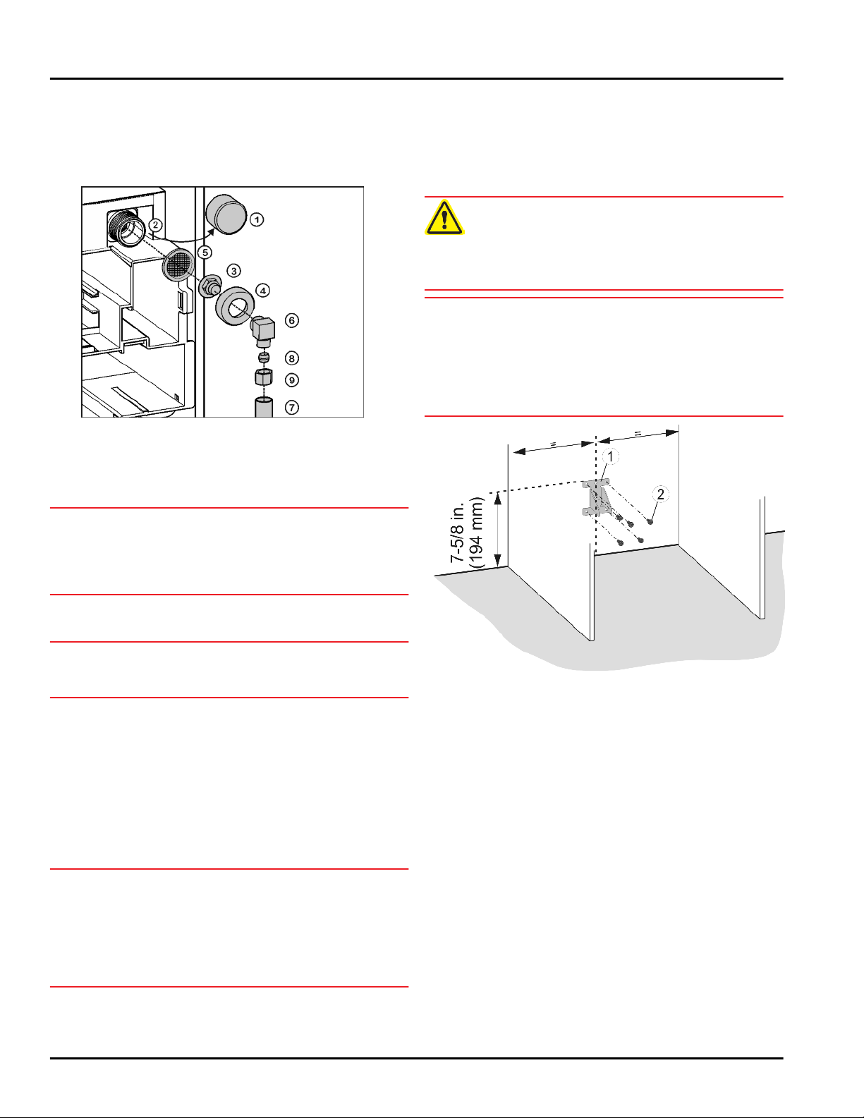
Fig. 27
Remove the cap
u
Fig. 27 (2)
Insert the coupler
u
Insert the water filter
u
down towards the coupler
.
Fig. 27 (1)
Fig. 27 (3)
Fig. 27 (5)
from the solenoid valve
in theunion nut
with the recess pointing
Fig. 27 (3)
.
Fig. 27 (4)
.
9 Anti-tip device
The screws for fastening the anti-tip device are not
supplied with the appliance. Appropriate screws must be
used for the material (wood, concrete, etc.) in which the
safety device is mounted.
WARNING
Risk of injury if the appliance tips over!
Install the anti-tip device to prevent the appliance from
u
tipping over when the fully loaded door is open.
NOTICE
Risk of damage due to leaking water!
If the tilt safety device has been fitted in another position
than the one given, the water hoses may be damage
when pushing the appliance into the niche.
Only fit the tilt safety device in the position shown in the
u
diagram.
NOTICE
Risk of damage to the water filter!
If you insert the filter incorrectly you could damage it.
Insert the filter with the recess pointing towards the
u
coupler.
Lock the union nut
u
Fig. 27 (2)
NOTICE
Risk of damage to the thread!
Do not overtighten the union nut.
u
To turn the water connection 90°, tighten the elbow
u
connector
Connect the water supply
u
the aid of the clamp ring
the coupler
Before fitting into the cabinet:
Check the whole water system for leaks.
u
Before using for the first time:
Have the water line bled (remove air) by a competent
u
professional.
NOTICE
Malfunction of the water intake!
If the water intake is shut off during operation but the
IceMaker remains in operation, the water intake pipe may
ice up.
Switch off the IceMaker if the water supply is inter-
u
rupted (e.g. holiday).
and tighten.
Fig. 27 (6)
Fig. 27 (3)
Fig. 27 (4)
if necessary.
or elbow connector
onto the solenoid valve
Fig. 27 (7)
Fig. 27 (8)
and nut
(e.g. copper) with
Fig. 27 (9)
Fig. 27 (6)
to
.
Mark the installation position for the anti-tip device on
u
the wall or back of the unit.
Install the anti-tip device
u
screws
Fig. 28 (2)
.
Fig. 28 (1)
using appropriate
10 Single unit installation
Make sure you have the following tools on hand:
Torx screwdriver 10, 20
q
Cordless screwdriver, if necessary
q
1/4 in. bit attachment
q
Spirit level
q
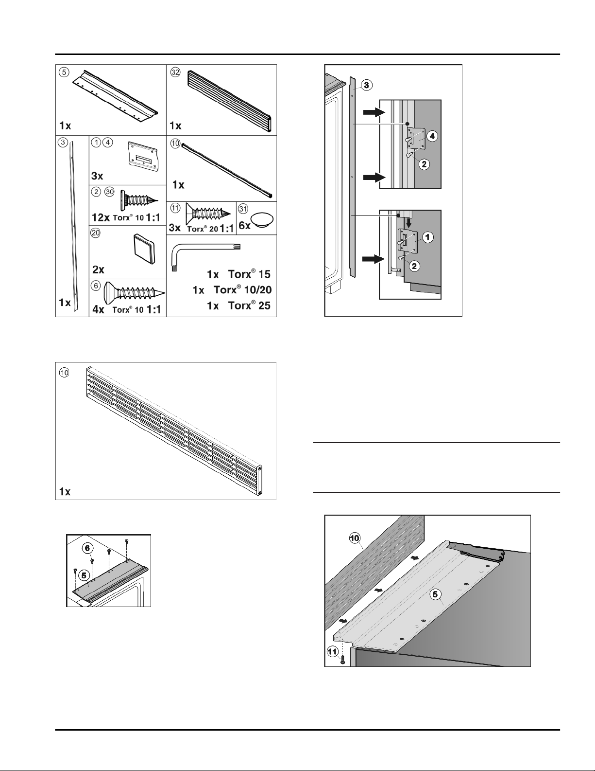
Kit 9900306 is required for the installation.
Fig. 28
* Depending on model and options 17
Page 18
Single unit installation
Fig. 29
The accessories kit 9900302 may be required depending
on the height of the recess. (see 4)
Fit retaining plate
u
Fig. 32 (1)
to the lower part of the
handle side by inserting two screws
pre-cut holes.
Slide installation strip
u
Fig. 32 (1)
Push second retaining plate
u
tion strip
from above.
Fig. 32 (3)
Fig. 32 (3)
Fig. 32 (4)
from above and screw to the center
of the side wall.
Push third retaining plate
u
strip
Fig. 32 (3)
from above and screw to the top part of
Fig. 32 (4)
the side wall.
Fig. 32
Fig. 32 (2)
into the
into the retaining plate
onto the installa-
onto the installation
Fig. 30
Install anti-tipping device inside the recess (see 9) .
u
Fig. 31
Screw on the upper installation contour
u
means of four screws
Fig. 31 (6)
inserted through the
Fig. 31 (5)
pre-cut holes in the profile and appliance.
Fit side installation strip:
Note
Depending on the recess height you will need to install
u
a ventilation grille or an end strip. Observe the
necessary ventilation cross-sections (see 5) .
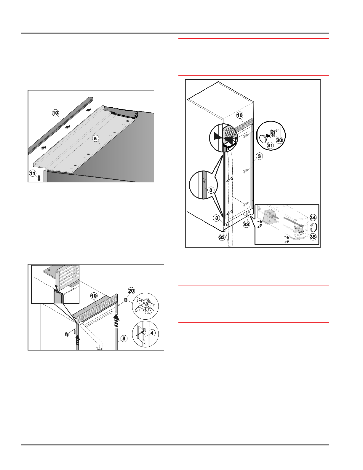
Fit upper ventilation grille (80”):
by
Fig. 33
Open the door.
u
18 * Depending on model and options
Page 19
Single unit installation
Position ventilation grille
u
contour
Fig. 33 (5)
Fig. 33 (10)
and align it such that the holes in
over the installation
ventilation grille and installation contour are above
each other.
Screw ventilation grille
u
Fig. 33 (5)
from below using three screws
Fig. 33 (10)
to installation contour
Fig. 33 (11)
.
Install end strip:
Fig. 34
Open the door.
u
Position end strip
u
contour
Fig. 34 (5)
Fig. 34 (10)
and align it such that the holes in
over the installation
ventilation grille and installation contour are above
each other.
Screw end strip
u
Fig. 34 (5)
from below using three screws
Fig. 34 (10)
to installation contour
Fig. 34 (11)
.
Secure side installation strips:
carry out the following steps for the hinge-side and the
handle-side strip:
NOTICE*
Risk of damage due to leaking water!
When pushing the appliance into the recess ensure
u
that the water connection does not kink or become
damaged.
Fig. 36
Push the appliance into the recess until the rear edge
u
of the ventilation grille
Fig. 36 (10)
is flush with the front
edge of the side wall of the cabinet.
Open the door.
u
NOTICE
Risk of damage to the castors.
Do not use a power tool to adjust the leveling rollers as
u
it will damage the leveling mechanism or disengage the
rod – instead use a hand ratchet.
Align appliance inside the recess above the roller
u
bases
Fig. 36 (33)
ment setting (1/4”)
foot and lower adjustment setting (1/4”)
Fig. 35
Remove adhesive tape from the side installation strip
u
Fig. 35 (3)
Push installation strip
u
touching the ventilation grille
Glue the adhesive plates
u
plate
respectively to the installation strip
.
Fig. 32 (1)
Fig. 35 (3)
Fig. 35 (20)
upwards until it is
Fig. 35 (10)
.
above the retaining
and the retaining plates
Fig. 35 (3)
Fig. 35 (4)
such that
it cannot slide downwards.
Install the appliance in the recess:
Connect appliance to the water supply (see 8) .*
u
Insert the power cable into the socket (see 14) .
u
* Depending on model and options 19
the front adjustable foot respectively. Turn clockwise to
raise and counterclockwise to lower. Maximum adjustable height: 5/8 in (16 mm).
At the top and bottom of the recess check the gap A
u
between the front edge of the installation strip
and the front edge of the side wall of the unit. It must be
1/2 ” (13 mm). Realign the appliance in the recess if
required.
Secure appliance inside the recess using three screws
u
Fig. 36 (30)
respectively. Do not scratch the side installation strip
Fig. 35 (3)
Place cover caps
u
when doing so.
using a spirit level: Use upper adjust-
Fig. 36 (34)
for the rear adjustable
Fig. 36 (35)
for
Fig. 36 (3)
on the handle side and the hinge side
Fig. 36 (31)
over the screws.
Page 20
Side-by-side installation
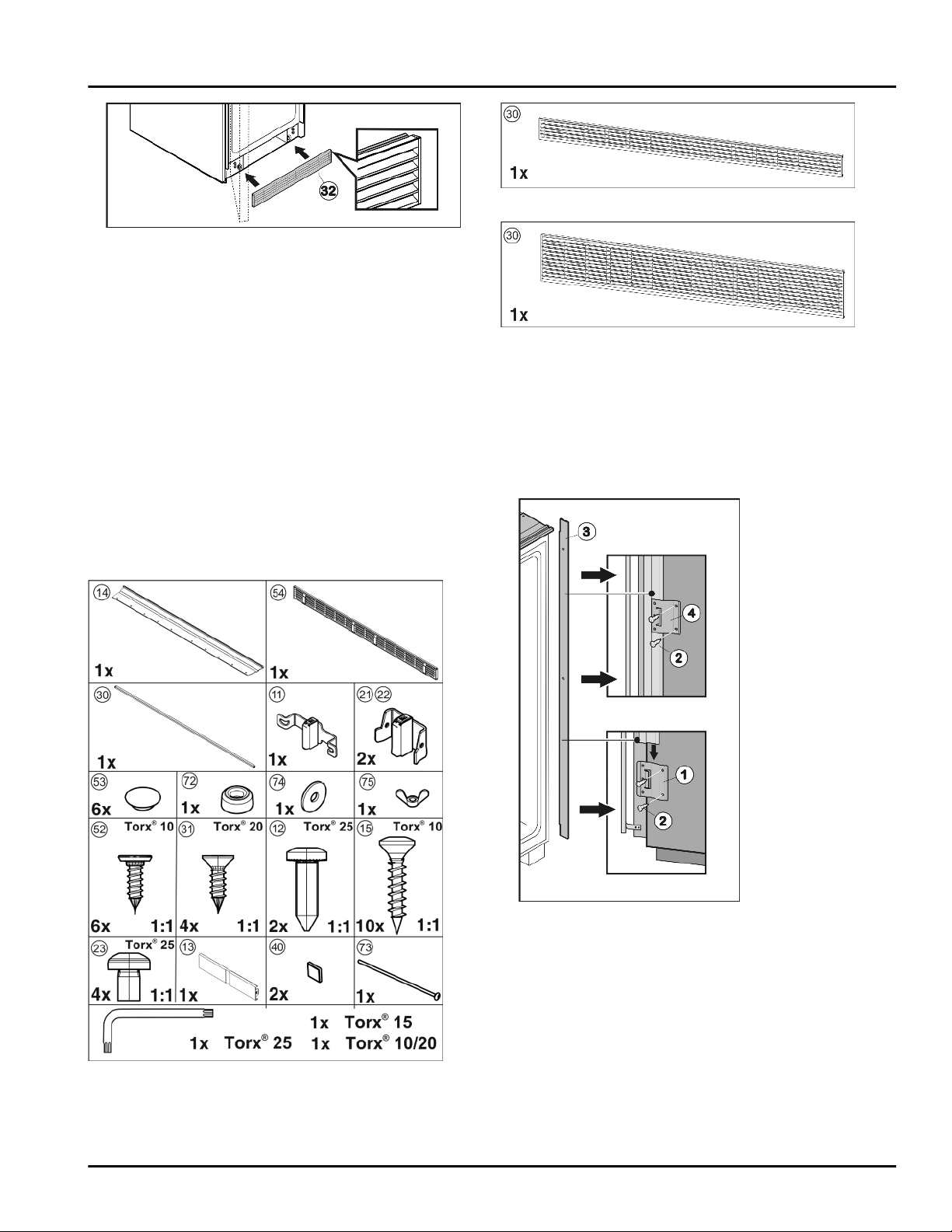
Fig. 37
If a water filter is used:
Insert water filter (see 13) .*
u
If no water filter is used:
Fit lower ventilation grille
u
such that the rubber lip is at the top. It is held in place
via magnets.
If necessary set the door opening angle (see 12) .
u
Fig. 37 (32)
flush with the floor
11 Side-by-side installation
The appliance with the ice maker must be on the left when
viewed from the front, the refrigerator unit on the right.
Make sure you have the following tools on hand:
Torx screwdriver 10, 15, 20, 25
q
Cordless screwdriver, if necessary
q
1/4 in. bit attachment
q
Spirit level
q
Fig. 39
Fig. 40
The accessories kit 9900304 or 9900344 may be required
depending on the height of the recess. (see 4)
Install anti-tipping device inside the recess (see 9) .
u
Fit side installation strips:
If the side on which the door hinges are located has been
changed, move the side installation strip to the hinge side
for both appliances.
Fig. 41
Unscrew retaining plates
u
Fig. 41 (3)
Fit retaining plate
u
hinge side by inserting two screws
pre-cut holes.
Slide rail
u
from above.
Push second retaining plate
u
above and screw onto the center of the side wall.
Push third retaining plate
Fig. 38
Kit 9900308 is required for the installation.
20 * Depending on model and options
u
above and screw onto the top part of the side wall.
Join appliances:
.
Fig. 41 (1)
Fig. 41 (3)
Fig. 41 (1,4)
to the lower part of the
into the retaining plate
Fig. 41 (4)
Fig. 41 (4)
and remove rail
Fig. 41 (2)
onto the rail from
onto the rail from
into the
Fig. 41 (1)
Page 21
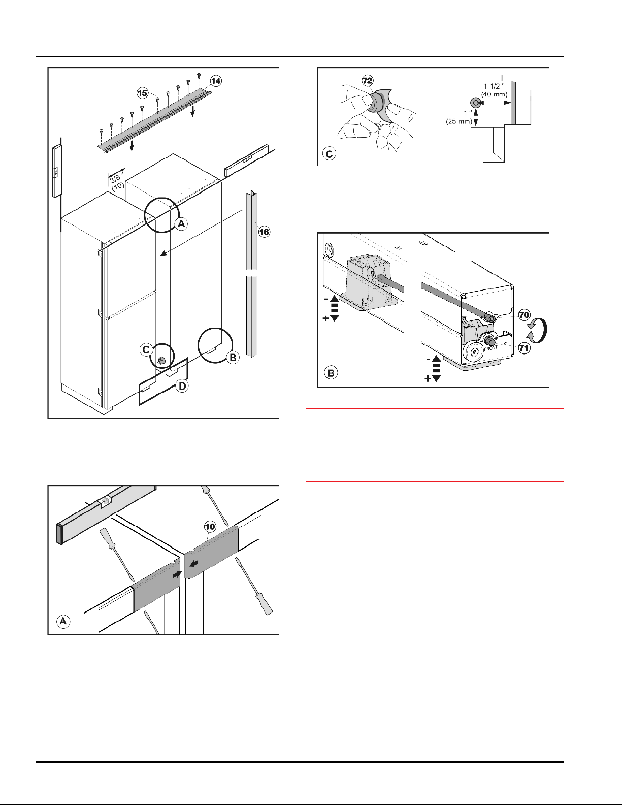
Side-by-side installation
Fig. 44
Glue spacer
u
Fig. 44 (72)
wall on the handle side, approximately 1.5 in. (40 mm)
as measured inwards from the front edge of the appliance.
onto the lower part of the side
Fig. 42
Position the appliances next to each other with a gap of
u
approximately 13/32 '' (10 mm) such that they are flush
at the front.
Open the door.
u
Fig. 43
Loosen covers
u
Fig. 43 (10)
using a screwdriver and pull
inwards to remove.
Fig. 45
NOTICE
Risk of damage to the castors.
When aligning appliance do not use a cordless screw-
u
driver on the castors or the height adjustment mechanism will be damaged or the adjusting rod may come
loose. Adjust the castors by hand.
Align the height of both appliances evenly using the
u
four roller bases. Use the upper adjustment setting
(1/4")
Fig. 45 (70)
lower adjustment setting (1/4")
for the rear adjustment foot and the
Fig. 45 (71)
for the front
adjustment foot. Turn clockwise to raise and counterclockwise to lower. Maximum adjustable height: 5/8 in
(16 mm).
Position end strip
u
Fig. 42 (14)
over the installation
contour and align it such that the holes in ventilation
grille and installation contour are above each other.
Screw on upper installation contour
u
the pre-cut holes using screws
Fig. 42 (14)
Fig. 44 (15)
through
.
* Depending on model and options 21
Page 22
Side-by-side installation
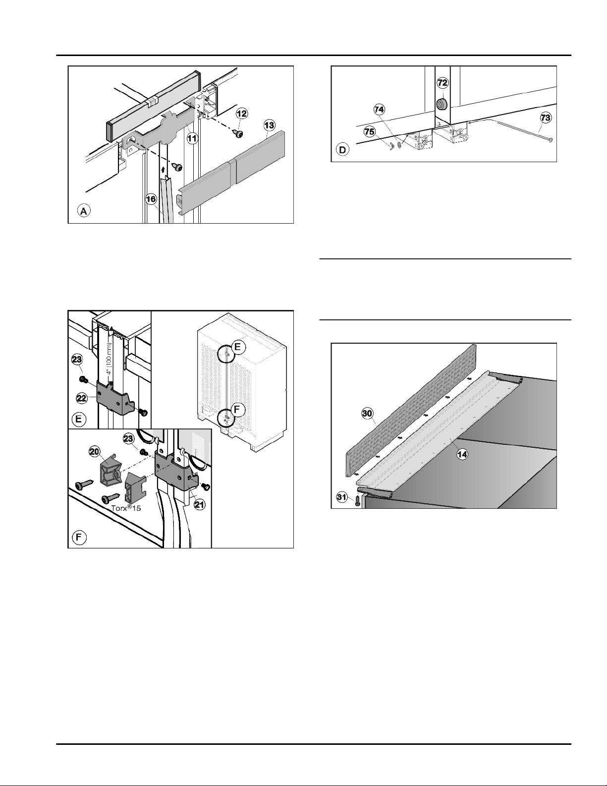
Fig. 46
Secure upperconnecting element
u
screws
Fig. 46 (12)
. Make preliminary holes (optional) or
use a cordless screwdriver.
Clip on cover panel
u
Push appliances together at the bottom and realign if
u
Fig. 46 (13)
necessary.
Fig. 46 (11)
.
using two
Fig. 48
Insert long carriage bolt
u
Push washer
u
Fig. 48 (74)
Fig. 48 (73)
and nut
screw. Tighten nut until the spacer
.
Fig. 48 (75)
Fig. 48 (72)
onto the
touching the opposite side wall.
Fit strip
u
Fig. 46 (13)
Tighten the screws
u
Fig. 46 (16)
, push it slightly under the top cover
and then press it downwards into the gap.
Fig. 47 (23)
.
Note
Depending on the recess height, you will need to install
u
a ventilation grille (80”), a ventilation grille (84”) or an
end strip. Observe the necessary ventilation crosssections (see 5) .
Fit upper ventilation grille (80 or 84”):
is
Fig. 49
Open the door.
u
Position ventilation grille
u
Fig. 47
Remove the spacers
u
Fig. 47 (20)
from the lower reverse
side of the appliances.
Position the upper connecting piece and
u
Fig. 47 (23)
Position upper connecting piece
u
Fig. 47 (23)
22 * Depending on model and options
screw
Fig. 47 (21)
on from the side.
on from the side.
Fig. 47 (22)
and screw
contour
ventilation grille and installation contour are above
each other.
Screw ventilation grille
u
from below using four screws
Fit end strip:
Fig. 42 (14)
Fig. 49 (30)
and align it such that the holes in
Fig. 49 (30)
over the installation
to installation contour
Fig. 49 (31)
.
Page 23
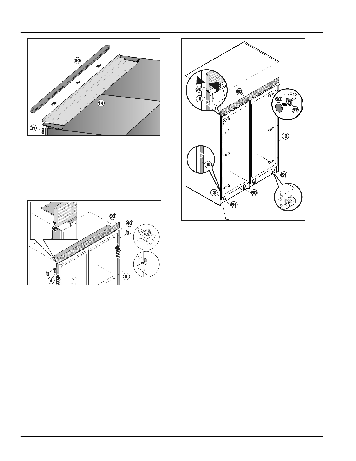
Fig. 50
Open the door.
u
Position end strip
u
contour
Fig. 42 (14)
Fig. 50 (30)
over the installation
and align it such that the holes in
ventilation grille and installation contour are above
each other.
Screw end strip
u
below using four screws
Fig. 50 (30)
Fig. 50 (31)
to installation contour from
.
Secure side installation strip:
Side-by-side installation
Fig. 51
Remove adhesive tape from the side installation strip
u
Fig. 51 (3)
Push installation strip
u
touching the ventilation grille
Glue the adhesive plates
u
plate
respectively to the installation strip
.
Fig. 41 (1)
Fig. 51 (3)
Fig. 51 (40)
upwards until it is
Fig. 51 (30)
.
above the retaining
and the retaining plates
Fig. 51 (3)
Fig. 51 (4)
such that
it cannot slide downwards.
Install the appliance in the recess:
Connect appliance to the water supply (see 8) .*
u
Insert the power cable into the socket (see 14) .
u
Fig. 52
Push the appliance into the recess until the rear edge
u
of the ventilation grille
Fig. 52 (30)
is flush with the front
edge of the side wall of the cabinet.
Open the door.
u
Completely screw in the two centre roller bases
u
Fig. 52 (50)
at the front and rear such that the appliance
is only resting on the outer roller bases. This enables
the two appliances connected to each other to be
aligned jointly like a single appliance.
Align appliance inside the recess by adjusting the outer
u
roller bases
At the top and bottom of the recess check the gap A
u
between the front edge of the installation strip
Fig. 52 (51)
and using a spirit level.
Fig. 52 (3)
and the front edge of the side wall of the unit. It must be
1/2 ” (13 mm). Realign the appliance in the recess if
required.
Secure appliance inside the recess using three screws
u
Fig. 52 (52)
the side installation strip
Place cover caps
u
Being careful not to affect the level, lower the levelling
u
wheels in the center roller bases
hinge side of each appliance. Do not scratch
Fig. 52 (3)
Fig. 52 (53)
when doing so.
over the screws.
Fig. 52 (50)
until they
are resting on the floor.
* Depending on model and options 23
Page 24
Adjusting the door opening angle
Fig. 53
If a water filter is used:
Insert the water filter (see 13) .*
u
If no water filter is used:
Fit lower ventilation grille
u
such that the rubber lip is at the top. It is held in place
via magnets.
If necessary set the door opening angle (see 12) .
u
Fig. 52 (54)
flush with the floor
12 Adjusting the door opening angle
The appliance is delivered with a door opening angle of
110°. If the angle needs to be limited to 90° an opening
limiter must be used on the soft stop mechanism. Carry
out the following steps for all soft stop mechanisms on the
appliance (the top soft stop mechanism is illustrated):
NOTICE
Risk of damage for the door!
If no opening limiter is fitted and the door is opened, it can
hit the side installation strip and scratch as a result. For
this reason the appliance is already equipped with an
opening limiter (110°) as delivered from the factory.
Always fit an opening limiter (110° or 90°)!
u
When fitting the opening limiter open the door carefully
u
and do not allow it to hit anything!
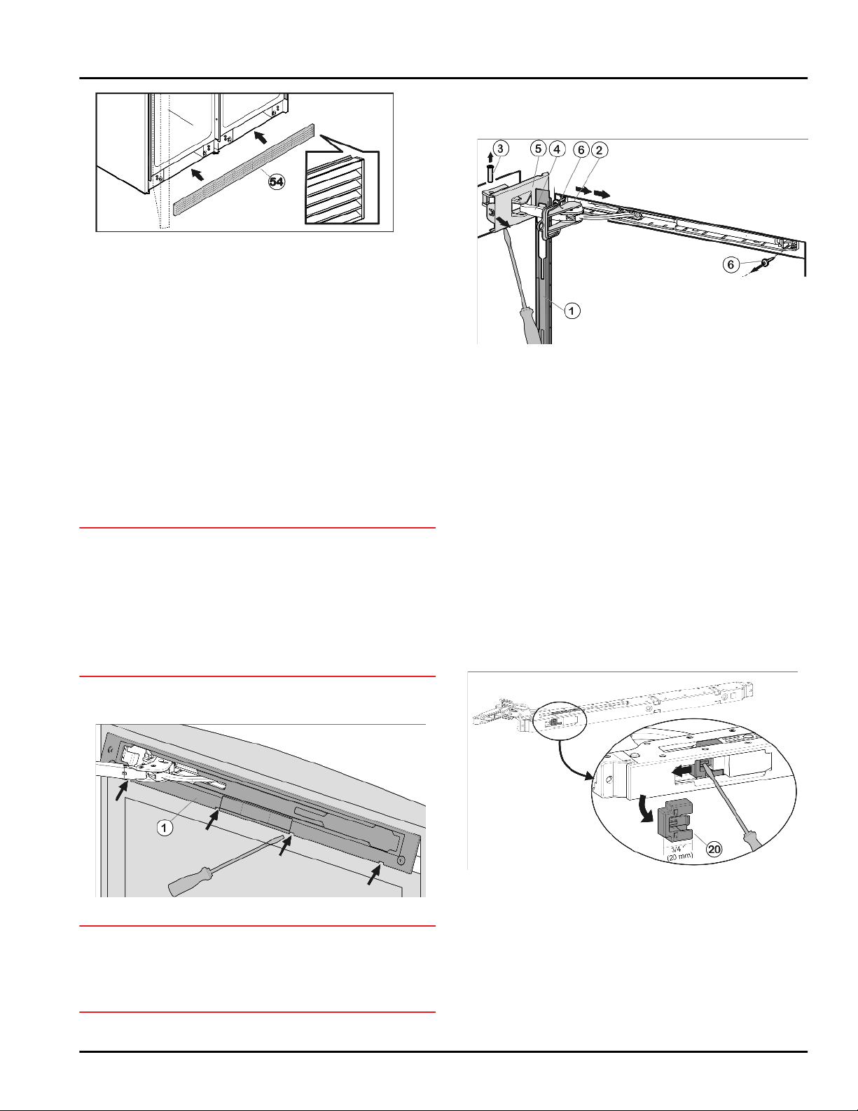
Release panel
u
remove.
The panel hangs above the damper bracket.
w
Push panel forward over the damper bracket
u
in the direction of the appliance.
Engage locking device
u
oblong hole.
The locking device prevents the hinge from snapping
w
shut.
Unscrew cover that is on the hinge side
u
the first notch using a screwdriver.
The bolt will become visible.
w
Push bolt
u
Press damper bracket
u
door.
Completely loosen cover that is on the hinge side
u
Fig. 55 (5)
Remove panel
u
Unscrew soft stop unit (2 x Torx 15)
u
Slightly pull out soft stop unit, push it towards the
u
handle side and open it out.
Fit opening limiter:
Fig. 54 (1)
Fig. 55 (3)
and remove.
Fig. 55 (1)
using slotted screwdriver and
Fig. 55 (2)
out from below.
Fig. 55 (4)
.
into place inside
Fig. 55 (5)
in the direction of the
Fig. 55 (6)
Fig. 55 (4)
.
Fig. 55
until
Removing the soft stop unit
Open the door.
u
Fig. 56
Remove opening limiter (110°)
Fig. 54
NOTICE
Risk of damage!
If the door seal is damaged the door may not close properly and the level of cooling is insufficient.
Do not damage the door seal with the screwdriver!
u
24 * Depending on model and options
u
mechanism: Press down notch using screwdriver and
pull off opening limiter
Fig. 56 (20)
Fig. 56 (20)
.
on soft stop
Page 25
Installing the water filter
Fit opening limiter (90°)
u
Fig. 57 (21)
supplied: insert it
into the soft stop mechanism from the side and push in
until it audibly snaps into place.
Re-attaching the soft stop mechanism:
Fig. 57
Hook panel
u
Fig. 59 (1)
into the damper bracket
Fig. 59 (4)
such that the detent hooks are pointing inwards and the
front side is facing the appliance.
Push on cover
u
over the bearing part
Place cover
u
Fig. 59 (5)
Fig. 59 (8)
Fig. 59 (5)
from the outside (A) and pivot
(B).
on top and allow to snap into
place until the first notch.
The openings for the bolts lie above each other after
w
positioning the damper bracket.
Pull damper bracket
u
insert bolt
Fig. 59 (3)
Fig. 59 (4)
towards bearing part and
from above such that the square
head is resting in the recess.
Now snap cover
u
bearing part
Check that the cover is positioned correctly such that
w
Fig. 59 (5)
Fig. 59 (8)
completely into place on the
.
the door can close properly and the bolt is secured.
Remove locking device
u
Snap panel
u
Fig. 59 (1)
Fig. 59 (2)
by twisting it.
into place on the door.
13 Installing the water filter*
The water filter guarantees optimal water quality and
should be installed the first time you use the appliance.
Alternatively, the appliance can also be operated without
the water filter.
Fig. 58
With the hinge of the upper soft stop unit facing the
u
door hinge side, engage the soft stop unit (A) and
swivel inwards (B).
The holes on the left and right must lie exactly above
w
each other.
Tighten soft stop unit (2 x Torx 15)
u
Fig. 58 (7)
.
Note
Follow the correct sequence. First hang the panel over
u
the damper bracket, then the cover.
Flow rate 0.5 gpm (1.89 lpm)
Water connection Drinking water
Water pressure 40 psi - 90 psi ( 2.8 bar - 6.2 bar/ 0.28 MPa
- 0.62 MPa )
Water temperature 33 °F - 100 °F ( 0.6 °C - 37 °C )
Capacity 300 gal. (1.14 l)
WARNING
Consuming contaminants can be harmful to your health!
If there is a chance the water may contain harmful
u
bacteria or if the water quality is unknown, do not use
this system without appropriate disinfection measures
upstream or downstream of the system.
Fig. 59
* Depending on model and options 25
Page 26
Connecting the appliance
NOTICE
Leakage water may damage the system!
Do not install this system on hot water lines. The
u
maximum operating temperature of the water in this
system is 100 °F (37.7 °C).
This system MUST be installed and used in compli-
u
ance with federal and local installation regulations.
Do not install under water hammer conditions. A water
u
hammer arrestor must be used to prevent water
hammering. If you are unsure how to check these
conditions, consult a professional installer.
Do not install with a water pressure greater than 90 psi
u
(6.2 bar). If your water pressure exceeds 80 psi, install
a pressure limiting valve. If you are unsure how to
check the water pressure, consult a professional
installer.
Protect against frost; if temperatures below 33 °F
u
(0.6 °C) are expected, remove the filter.
When used as indicated, the disposable filter
u
cartridges must be replaced every 6 months or whenever you notice a considerable decrease in the flow
rate.
Write the date of the next filter replacement on the label
u
Fig. 61 (8)
Fig. 61 (6)
Close the filter change flap
u
Fit ventilation grille
u
Make sure the filter is leak-tight and no water is coming
u
out.
Note
New water filters may contain particulate matter.
Do not consume or use ice cubes produced within 72
u
hours after replacing the filter.
The water filter is now ready for use.
w
supplied and affix it to the filter cover
.
Fig. 61 (1)
Fig. 60 (3)
.
.
14 Connecting the appliance
WARNING
Electrical shock hazard!
Start-up should only take place once the appliance has
u
been installed according to these instructions.
Electrically ground appliance.
u
Do not ground to a gas pipe.
u
Check with a qualified electrician if you are not sure the
u
appliance is properly grounded.
Do not have a fuse in the neutral or grounding circuit.
u
Do not use an extension cord, power bar or a multiple
u
socket adapter.
Do not use a power cord that is frayed or damaged.
u
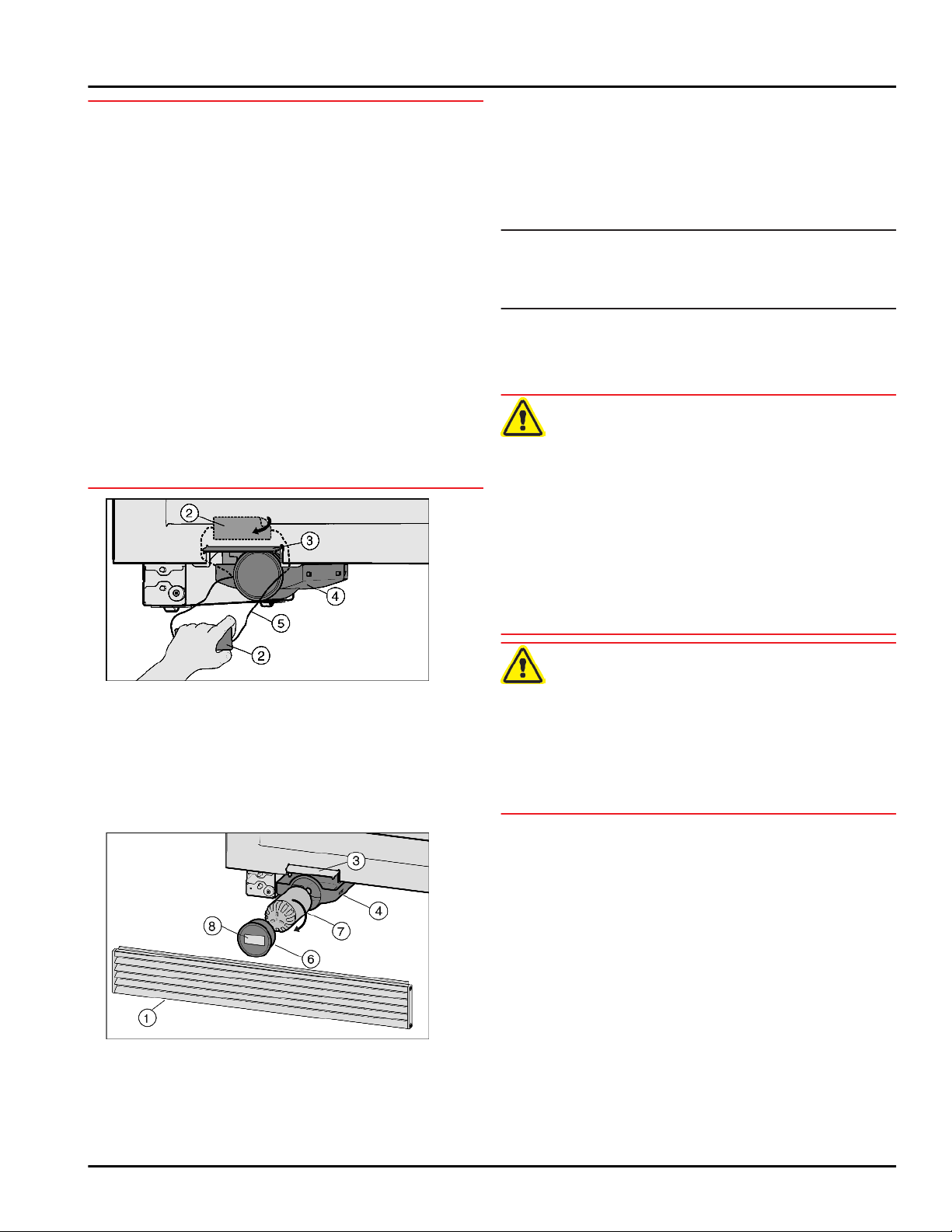
If necessary, remove ventilation grille
u
Remove any labels
u
Open the filter change flap
u
Carefully pull out drawer
u
Fig. 60 (5)
Cut off the string
u
Fig. 60 (2)
be disposed of.
Remove the filter cover
u
Insert water filter
u
100° clockwise as far as it will go.
Insert the drawer
u
Place the cover
u
.
and pull out. It is no longer required and can
Fig. 60 (2)
Fig. 60 (5)
Fig. 61 (6)
Fig. 61 (7)
Fig. 61 (4)
Fig. 61 (6)
from the appliance.
Fig. 60 (3)
Fig. 60 (4)
and turn it approximately
.
on the filter.
Fig. 60
Fig. 61 (1)
.
by the string
together with the label
.
.
Fig. 61
WARNING
Electrical shock hazard!
This appliance is equipped with a three-prong (grounding)
polarized plug for your protection against possible shock
hazards. Electrical Grounding Required.
Do not remove the round grounding prong from the
u
plug.
Use only an grounded adapter.
u
Wait 1 hour after installation before you plug in the
appliance. This allows the refrigerant and system lubrication to reach equilibrium.
Make sure incoming voltage is the same as the appli-
ance rating. A 110-120 Volt, 60 Hz, 15 Amp electrical
supply (20 Amp for side-by-side installations) circuit
that is controlled by a circuit breaker or fuse is required.
We recommend using a dedicated circuit for this appli-
ance to prevent electrical overload.
Follow all Federal, State and local electrical, fire and
building codes and ordinances when installing the
receptacle and / or the appliance.
In some communities, a wall switch is required to turn
power to the appliance ON and OFF.
To reduce the risk of fire, electric shock, or personal
injury, installation work and electrical wiring must be
done by a qualified electrician in accordance with all
applicable codes and standards, including fire-rated
construction.
26 * Depending on model and options
Page 27

The Power Plug must be easily accessible so that the
appliance can be disconnected from the mains quickly
in an emergency. It must not be behind the back of the
appliance.
The top of the electric outlet must be located within
82-5/8 in. (2100 mm) from the top of the base in the
cabinet.
Connecting the appliance
* Depending on model and options 27
Page 28

For Service in the U.S.:
Liebherr Service Center
Toll Free: 1-866-LIEBHER or 1-866-543-2437
[email protected]
PlusOne Solutions, Inc.
3501 Quadrangle Blvd, Suite 120
Orlando, FL 32817
For Service in Canada:
Liebherr Service Center
Toll Free: 1-888-LIEBHER or 1-888-543-2437
www.euro-parts.ca
EURO-PARTS CANADA
39822 Belgrave Road
Belgrave, Ontario, N0G 1E0
Phone: (519) 357-3320
Fax: (519) 357-1326
www.liebherr-appliances.com
Part No. 7084602 - 02
 Loading...