

Page 1
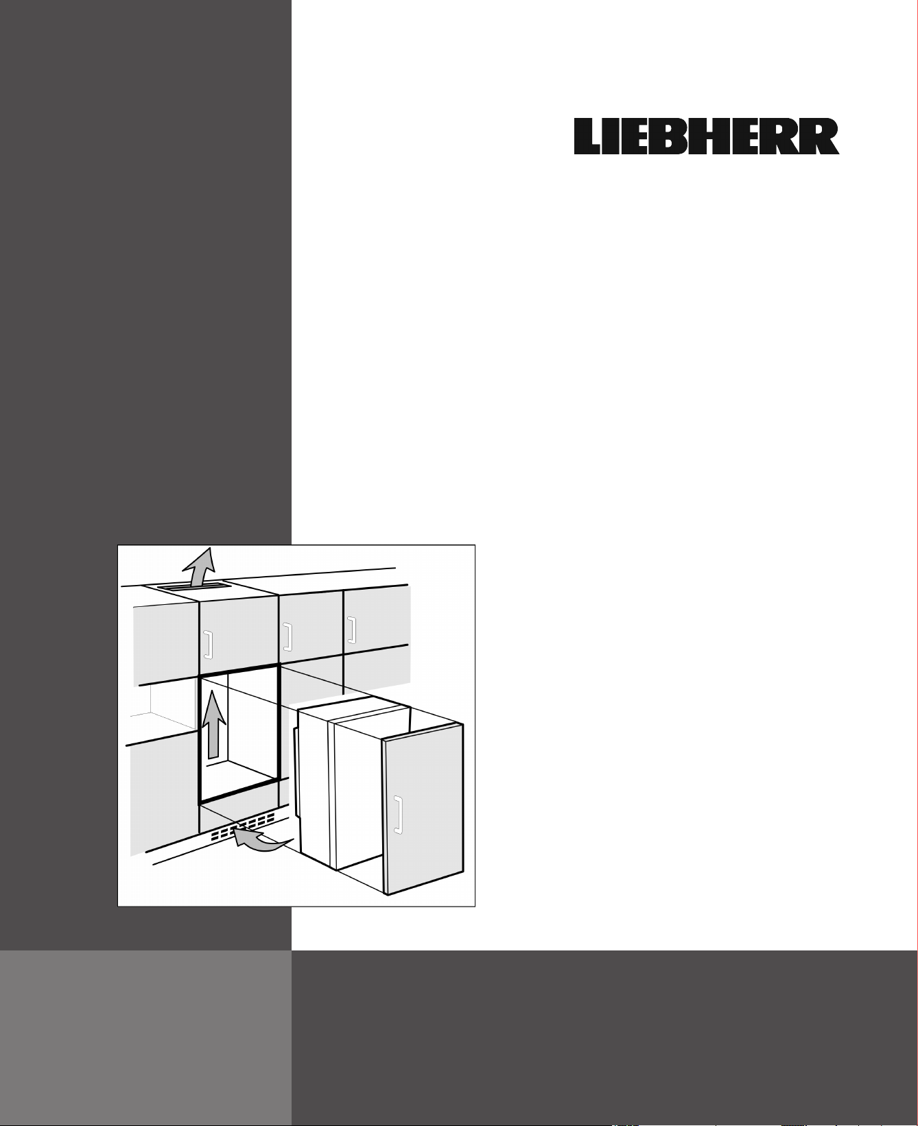
Installation
Instructions
Refrigerators and freezers for
integrated use, door slider
Instrucciones
de montaje
Frigorífico y congelador,
integrable, puerta orientable
Instructions
de montage
Congélateurs et réfrigérateurs,
intégrables, porte oscillante
HC700B
020316 7086428 - 00
Page 2
General safety information
Contents
1 General safety information........................... 2
2 Transporting the appliance........................... 2
3 Setting up the device..................................... 2
4 Appliance dimensions................................... 3
5 Recess dimensions....................................... 4
6 Cabinet door................................................... 4
7 Air circulation in the kitchen cabinet........... 6
8 Reversing the door........................................ 6
9 Installing the appliance in the recess.......... 8
10 Disposal of packaging................................... 13
11 Connecting the appliance............................. 14
The manufacturer is constantly working to improve all
models. Therefore please understand that we reserve the
right to make design, equipment and technical modifications.
To get to know all the benefits of your new appliance,
please read the information contained in these instructions carefully.
The instructions apply to several models, so there may be
differences. Sections which only apply to certain appliances are indicated with an asterisk (*).
Instructions for action are marked with a , the
results of action are marked with a .
mains quickly in an emergency. It must not be
behind the back of the appliance.
DANGER indicates a hazardous situation,
which if not avoided, will result in
death or serious injury.
WARNING indicates a hazardous situation,
which if not avoided, could result in
death or serious injury.
CAUTION indicates a hazardous situation,
which if not avoided, will result in
minor or moderate injury.
NOTICE indicates a hazardous situation,
which if not avoided, could result in
damage to property.
Note indicates useful advice and tips.
2 Transporting the appliance
CAUTION
Risk of injury or damage if incorrectly transported.
Transport the appliance in its packaging.
u
Transport the appliance upright.
u
Do not move the appliance on your own.
u
3 Setting up the device
1 General safety information
-
Read and follow these instructions. They
contain safety advice which is important for
safe and problem-free installation and operation. Always read and follow the safety advice.
-
It is important that the guidelines and instructions in this manual are followed so that the
appliance is correctly installed and operates
properly Read and understand all information
in this manual before the appliance is installed
-
Risk of asphyxiation and crushing:
Remove doors and shelves from old appliances to prevent them from becoming a potential hazard to children at play.
-
Only install, connect and dispose of the appliance in accordance with the instructions. Pay
particular attention to “niche dimensions”
(see 5) and “ventilation and fume extraction in
kitchen units” (see 7) .
-
The socket must be easily accessible so that
the appliance can be disconnected from the
WARNING
Risk of fire due to short circuit.
If the power cable or plug of the appliance or another
appliance and the back of the appliance touch each other
the power cable or plug will be damaged by the vibrations
of the appliance which could lead to a short circuit.
Install the appliance so that it does not touch any plugs
u
or power cables.
Do not connect the appliance or other appliances to the
u
sockets on the back of the appliance.
WARNING
Risk of fire due to moisture!
If live parts or the power cord get wet, this can cause a
short circuit.
The appliance is designed for use in enclosed spaces.
u
Do not operate the appliance in open space or in damp
areas or where there is spray.
Only operate the appliance after it has been installed.
u
2 * Depending on model and options
Page 3
WARNING
Risk of fire due to refrigerant.
The refrigerant contained within the appliance, R 600a, is
environmentally friendly, but flammable. Leaking refrigerant can ignite.
Do not damage the pipes of the refrigerant circuit.
u
WARNING
Danger of fire and damage!
Do not place devices that give off heat, e.g. micro-
u
waves, toasters, etc. on the appliance.
NOTICE
Risk of damage caused by water condensate!
Do not install this device directly beside another fridge/
u
freezer compartment.
NOTICE
Risk of damage for the finished floor surface!
Protect the finished floor surface before you uncrate the
u
unit.
WARNING
Danger of damage from overheating. May restrict operation.
Keep ventilation openings, in the appliance enclosure
u
or in the built-in structure, clear of obstruction.
Appliance dimensions
The load-bearing capacity of the floor must be sufficient
q
for the weight of the appliance plus about 1200 pounds
(544 kg) of food weight.
The electrical socket must assessed precisely to
q
ensure the correct position and fuse.
Do not restrict ventilation. Sufficient ventilation is
q
required for the appliance to operate correctly. The
ventilation grid fitted at the factory guarantees an effective ventilation gap on the appliance of 31 in.
(200 cm2). If you replace the ventilation grid with a
fascia, this must have at least the same size or larger
ventilation gap as the manufacturer's ventilation grid.
Note down the type (model, number), appliance name,
u
appliance or serial number, date of purchase and
manufacturer's address in the place provided for this in
the Use & Care Manual.
Remove all materials that could prevent it from being
u
installed properly or prevent proper ventilation from the
back or the side panels of the appliance.
After installation:
Remove protective films, adhesive tapes and transport
u
safety devices, etc.
Note
Clean the appliance (see operating instructions,
u
"Cleaning the appliance" section).
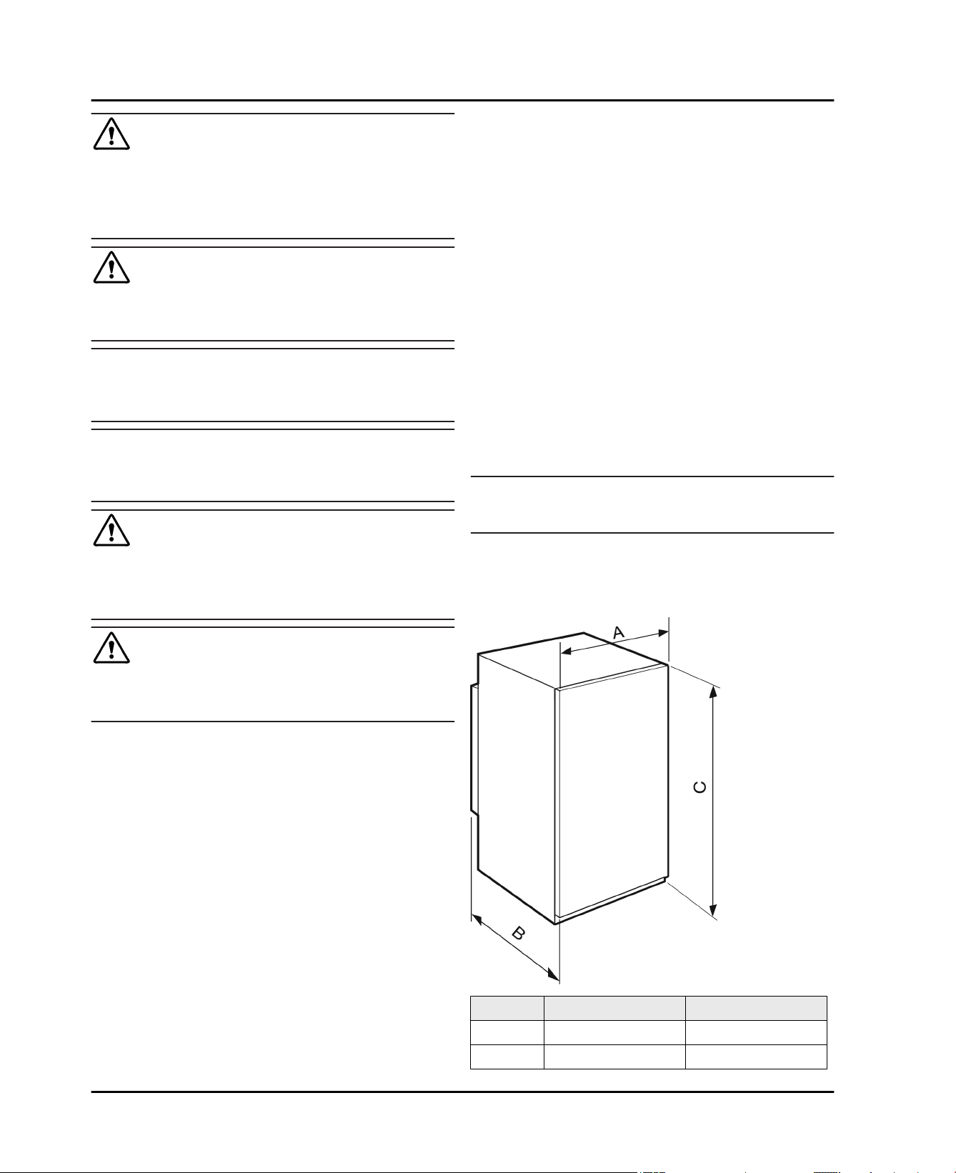
4 Appliance dimensions
2
WARNING
Danger of tilting.
To avoid a hazard due to instability of the appliance, it
u
must be fixed in accordance with the instructions.
If possible, have a professional install the appliance in
q
your kitchen cabinet unit.
If the appliance is damaged check with the supplier
q
immediately before connecting it.
The floor of the installation site must be horizontal and
q
level.
Do not install the appliance in direct sunlight or next to
q
an oven, heater or similar heat source.
Do not install the appliance on your own. It is better to
q
do this with two or more people.
The more R 600a refrigerant is in the appliance, the
q
larger the room must be where the device is located. In
the case of a leak, a flammable gas-air mixture may be
created in a room that is too small. In accordance with
standard EN 378, for every 0.39 oz (11 g) R 600a
coolant, the installation space must be at least35.5 ft
(1 m3). The amount of refrigerant in your appliance is
indicated on the identification plate inside the appliance.
If the appliance is installed in a very damp environment
q
condensate water may form on the outside of the appliance. Always ensure good ventilation.
3
in. mm
A
B
21 1/4 in. 540 mm
21 7/16 in. 544 mm
Fig. 1
* Depending on model and options 3
Page 4
Recess dimensions
in. mm
C
47 15/16 in. 1218 mm
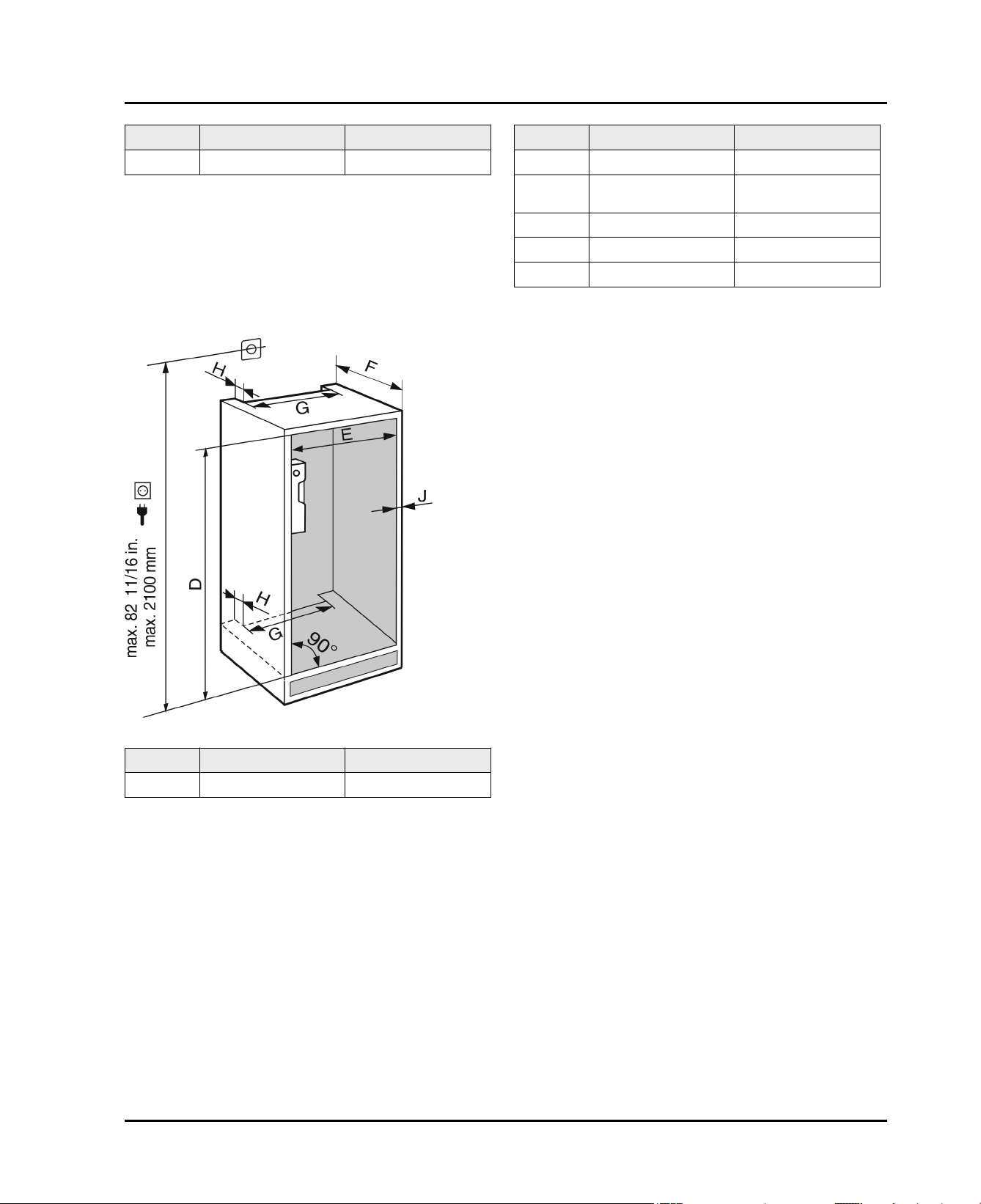
5 Recess dimensions
This is a built-in appliance and is therefore completely
enclosed by a kitchen cabinet The kitchen cabinet
surrounding the appliance must be designed exactly in
accordance with the specified fitting dimensions and must
allow sufficient air circulation to ensure correct operation
of the appliance.
in. mm
E
F
G
H
J
The declared energy consumption was determined with a
kitchen cabinet depth of 560 mm. The appliance is fully
functional with a kitchen cabinet depth of 550 mm but will
have a slightly increased level of energy consumption.
Check the wall thickness of adjacent cabinets: It must
u
be at least 16 mm.
Only install the appliance in solid, fixed kitchen cabi-
u
nets. Ensure that the cabinets cannot tip over.
Align the cabinets with a spirit level and a try square. If
u
necessary level them by putting something underneath
them.
Ensure that the floor and the side panels of the cabinet
u
are at right angles to each other.
22 — 22 3/4 560 — 578
min. 21 5/8, recom-
mended 22
min. 19 11/16 min. 500
min. 1 5/8 min. 40
max. 3/4 max. 19
min. 550, recom-
mended 560
6 Cabinet door
Fig. 2
A door is required for the kitchen cabinet.
The door must be at least 5/8 in. (16 mm) and no more
than 3/4 in. (19 mm) thick.
There must be a gap of at least 1/8 in. (3 mm) between
the door and the cupboard door above it (if there is
one).
The width of the cabinet door depends on the style of
the kitchen and the size of the gap between the door
panels of the cupboard. Normally a vertical gap of
1/8 in. (3 mm) should be left between the cabinet
doors.
If there are other cabinets the top edge of the cabinet
in. mm
D
48 — 48 5/8 1220 — 1236
door should be at the same height as the doors on the
adjacent cabinets.
The cabinet door must be assembled flat and free from
tension.
4 * Depending on model and options
Page 5
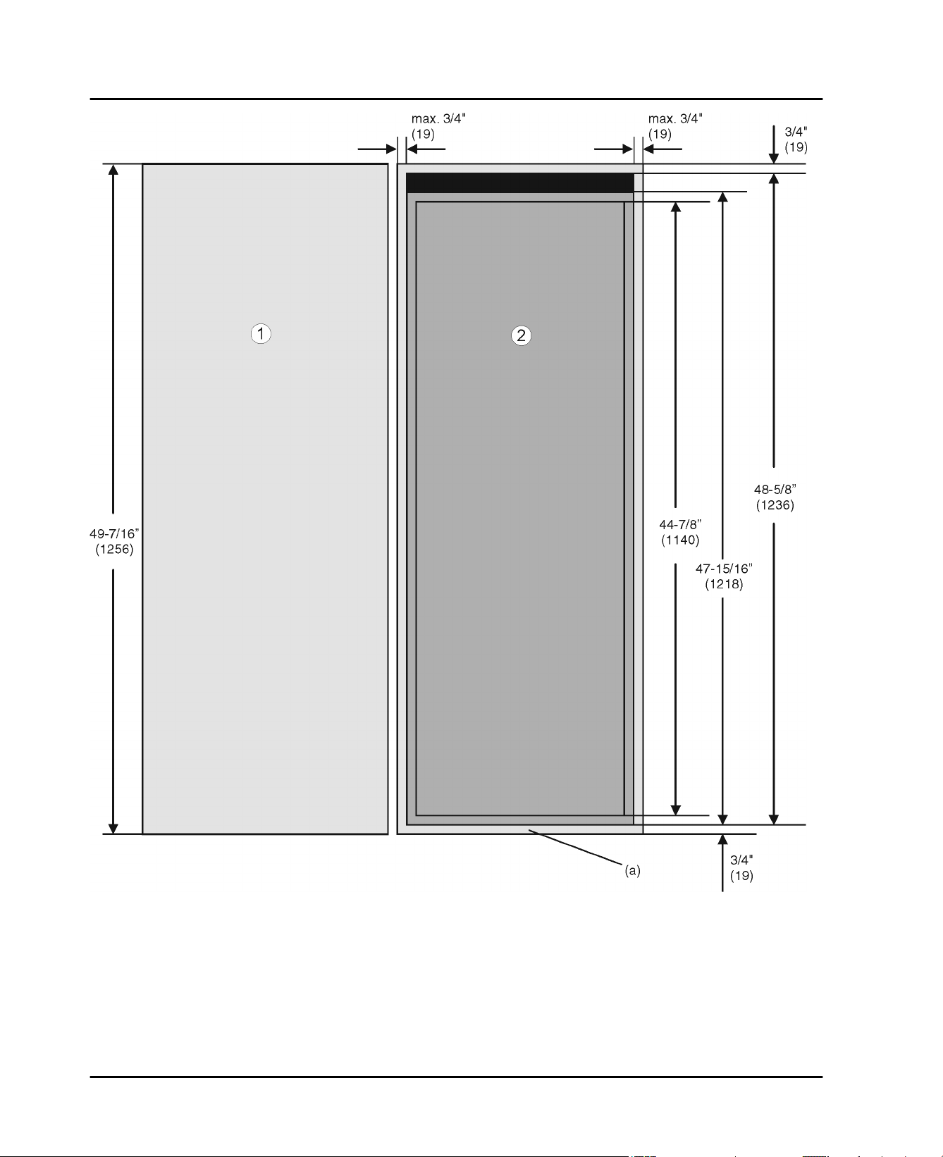
Cabinet door
Fig. 3
Total height of the cabinet (i.e. 49 7/16 in. (1256 mm))
plus thickness of the cover and floor plate
(normally 3/4 in. (19 mm)): 70 3/8 in. + 3/4 in. + 3/4 in. =
47 15/16 in. ( 1218 mm + 19 mm + 19 mm = 1256 mm )
* Depending on model and options 5
Fig. 3 (a)
Page 6
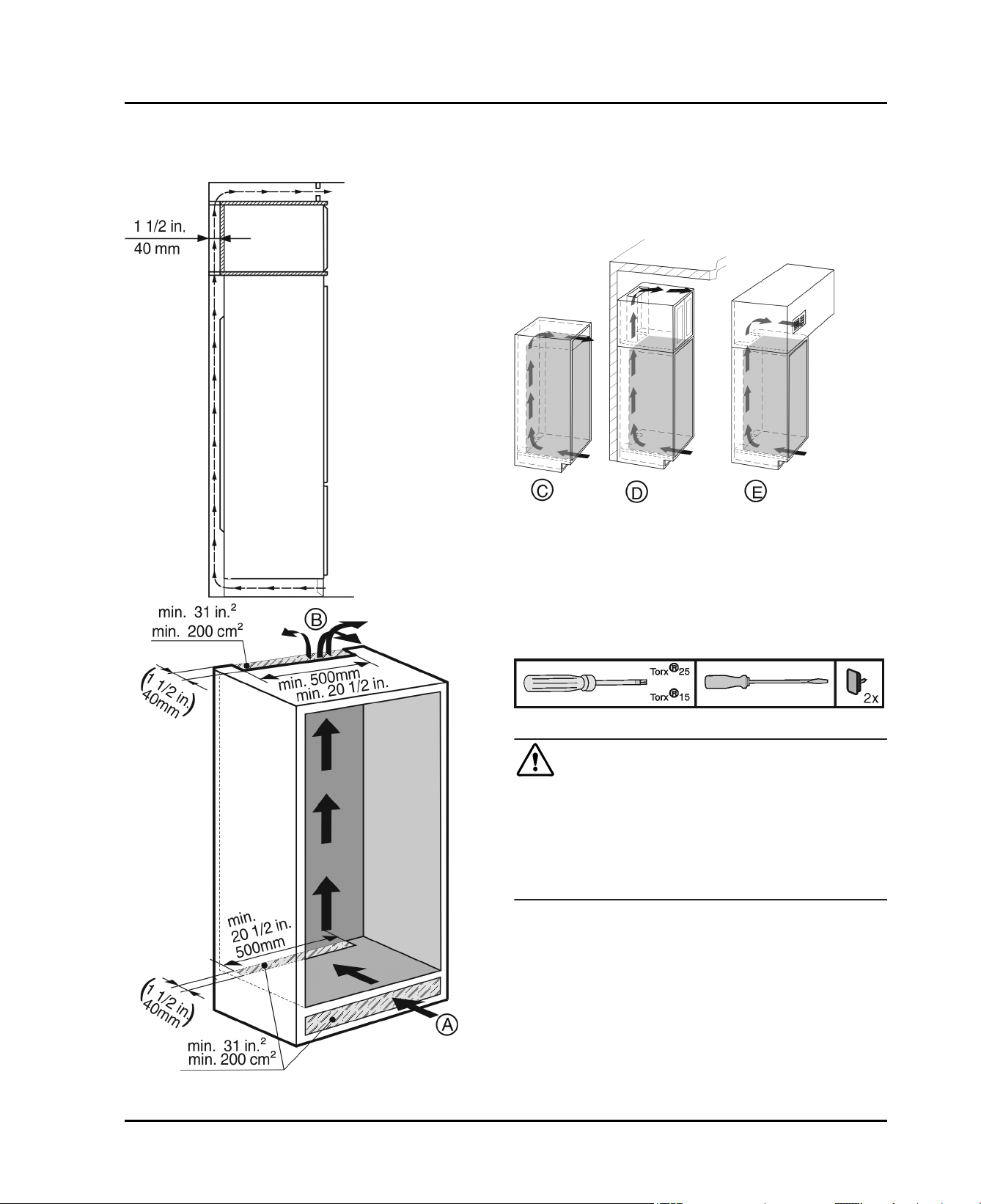
Air circulation in the kitchen cabinet
7 Air circulation in the kitchen cabinet
There must be an effective ventilation gap of at least
31 in2 (200 cm2) per device at the air inlet
air outlet
Basically, the bigger the ventilation gap, the more
energy-saving the operation of the appliance.
The depth of the ventilation shaft on the back wall of the
cabinet must be at least 1-1/2 in. (40 mm).
The top ventilation gap can be set up either directly
above the appliance with an optional ventilation grid
Fig. 6 (C)
as an air vent in a false ceiling
(B)
.
near the ceiling, above the cabinet
Fig. 6 (E)
.
(A)
and at the
Fig. 6 (D)
Fig. 6
or
Fig. 4
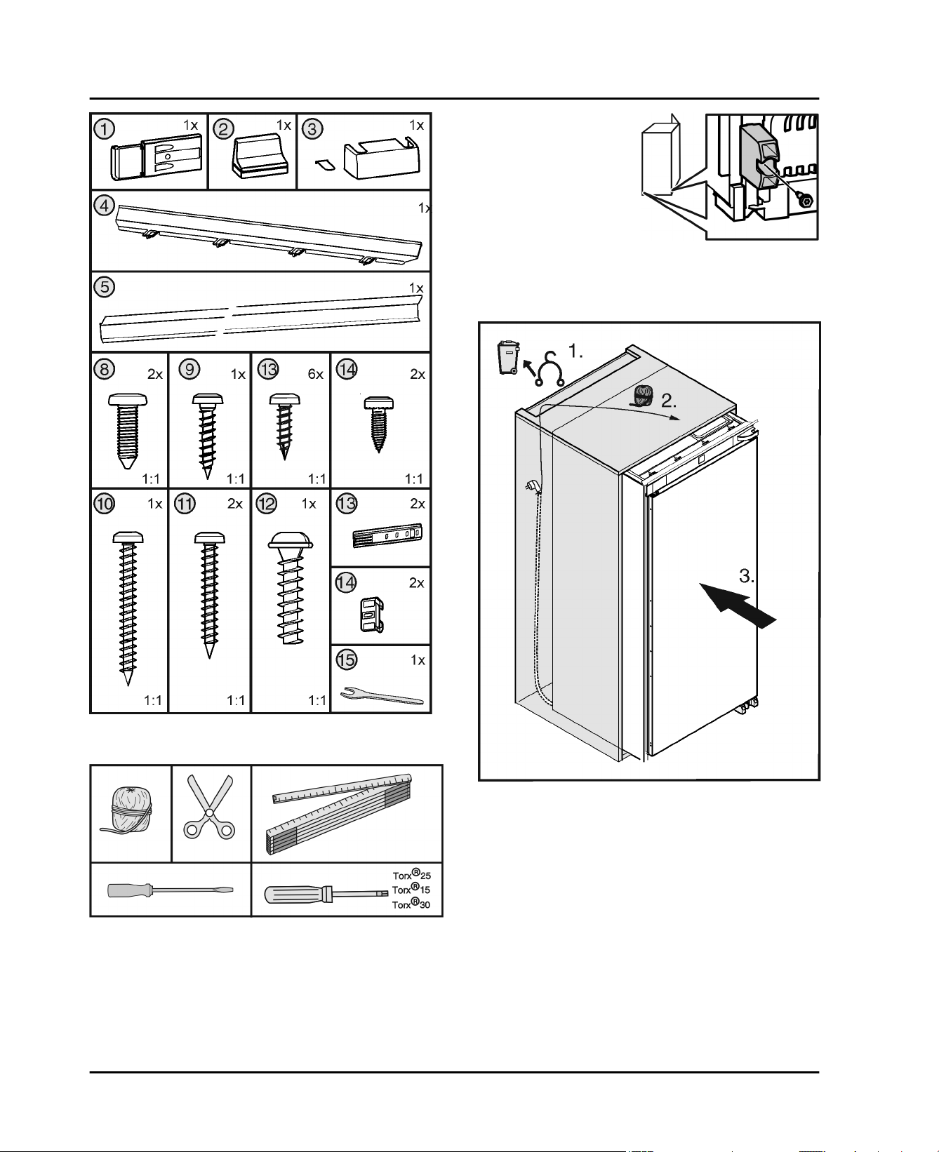
8 Reversing the door
Tool required:
Fig. 7
WARNING
Risk of injury if the door falls out.
If the fasteners are not screwed on tightly enough, the
door may fall out. This can result in serious injury. In addition, the door may not close, thus impairing the cooling
performance of the appliance.
Firmly tighten the top and bottom bearing brackets (to
u
4 Nm).
Fig. 5
6 * Depending on model and options
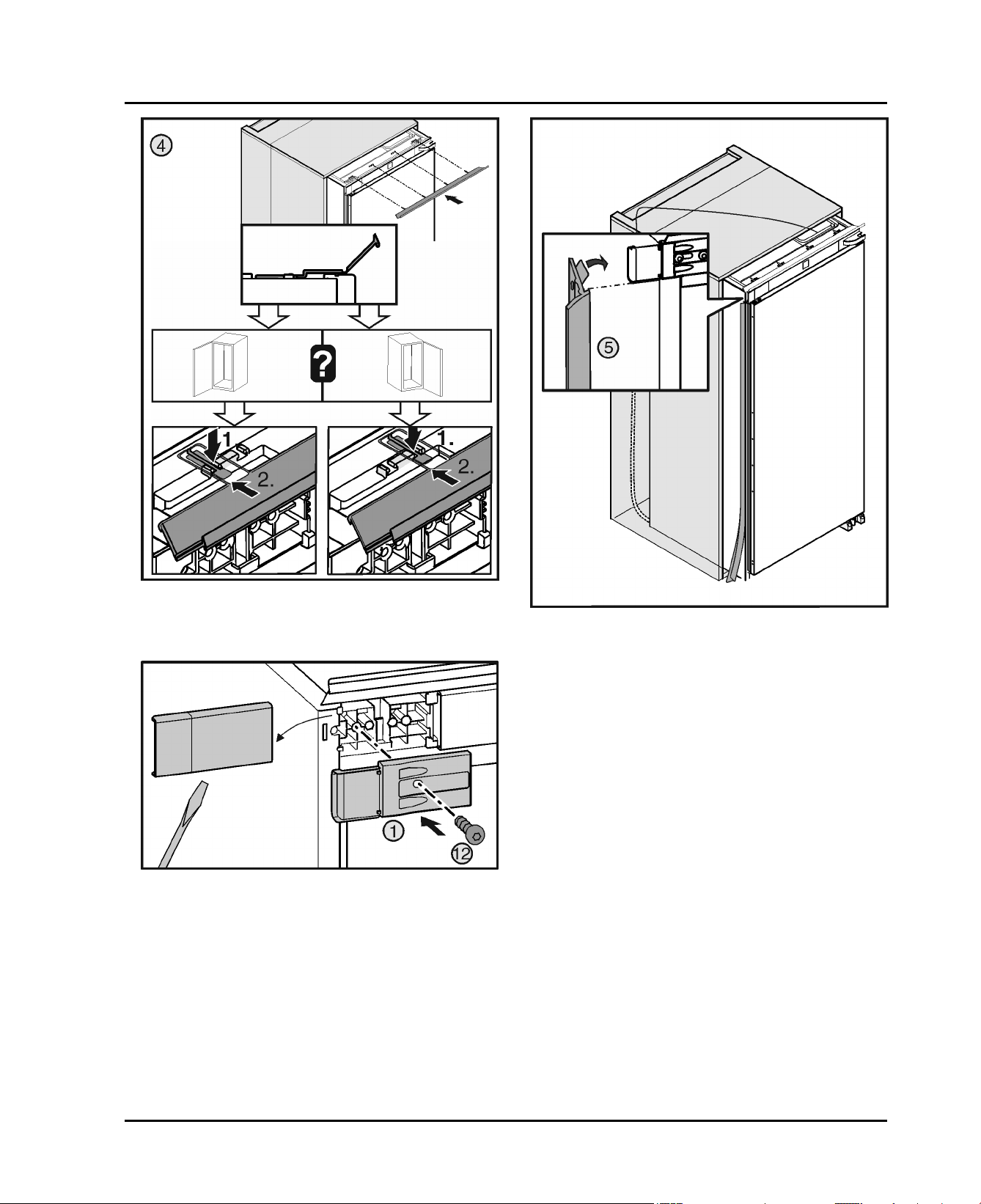
Page 7
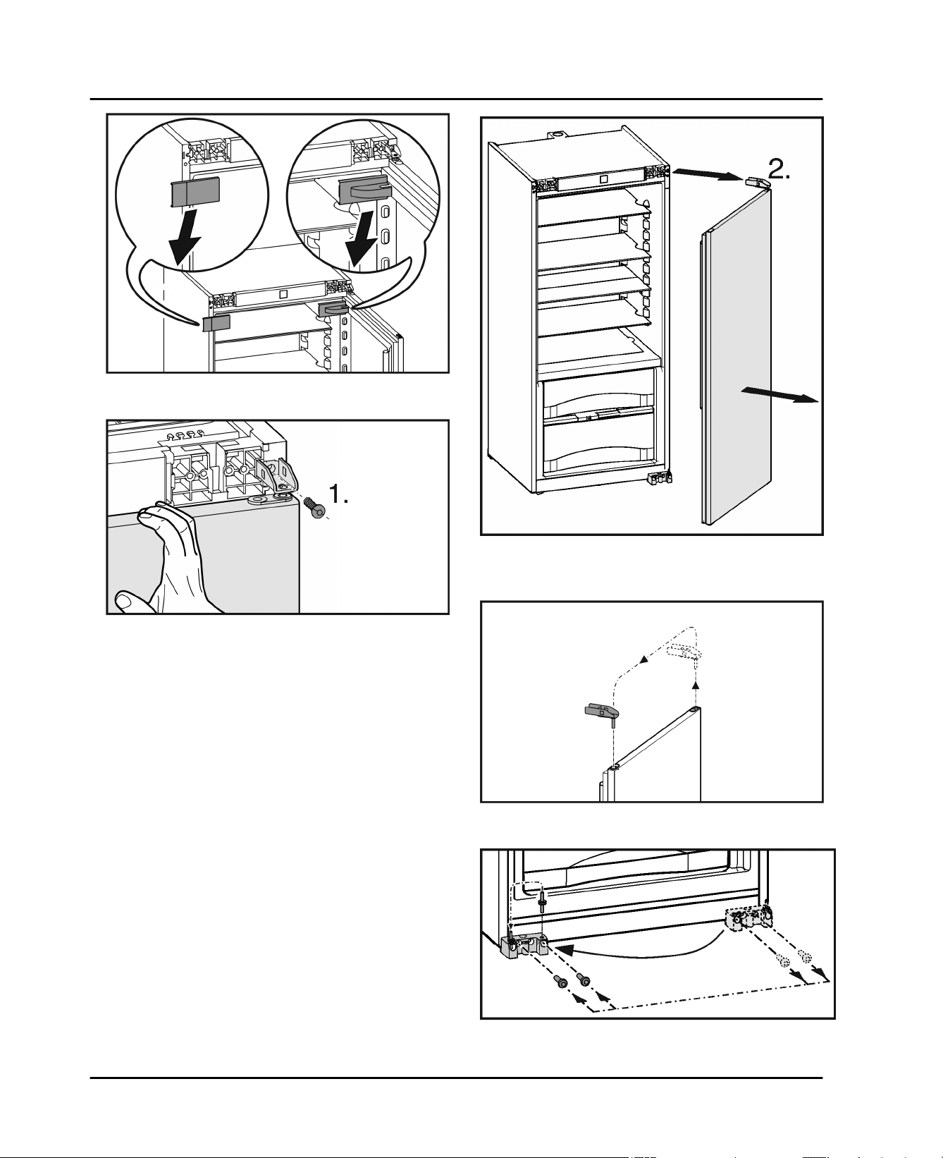
Fig. 8
Lift off covers. If necessary use a slotted screwdriver.
u
Reversing the door
Fig. 9
Fig. 10
Removing the door: Undo the screw (1) and remove the
u
door with the bearing (2).
Fig. 11
Swap the bearing.
u
Fig. 12
Swap the lower bearing bracket.
u
* Depending on model and options 7
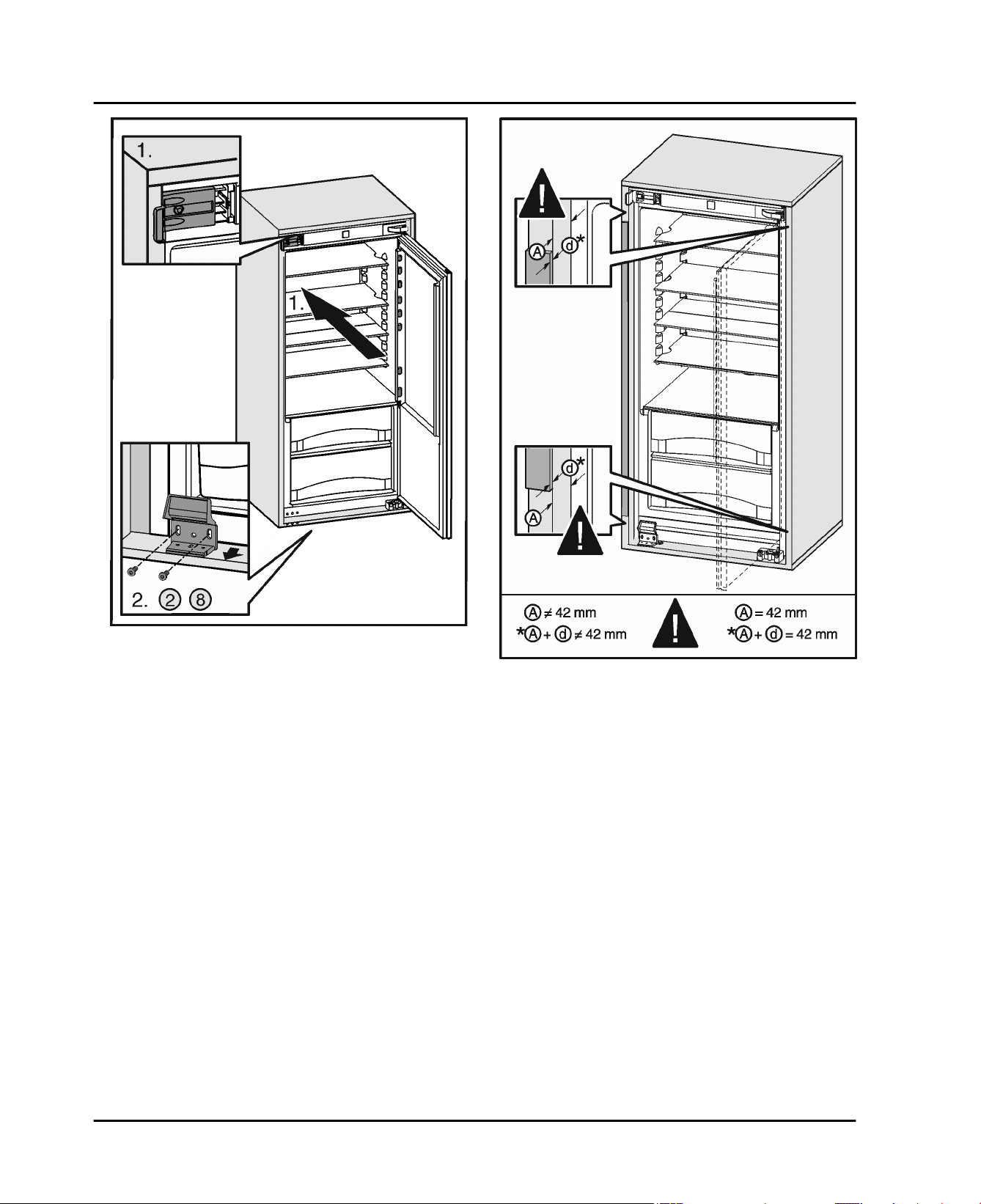
Page 8
Installing the appliance in the recess.
u
u
u
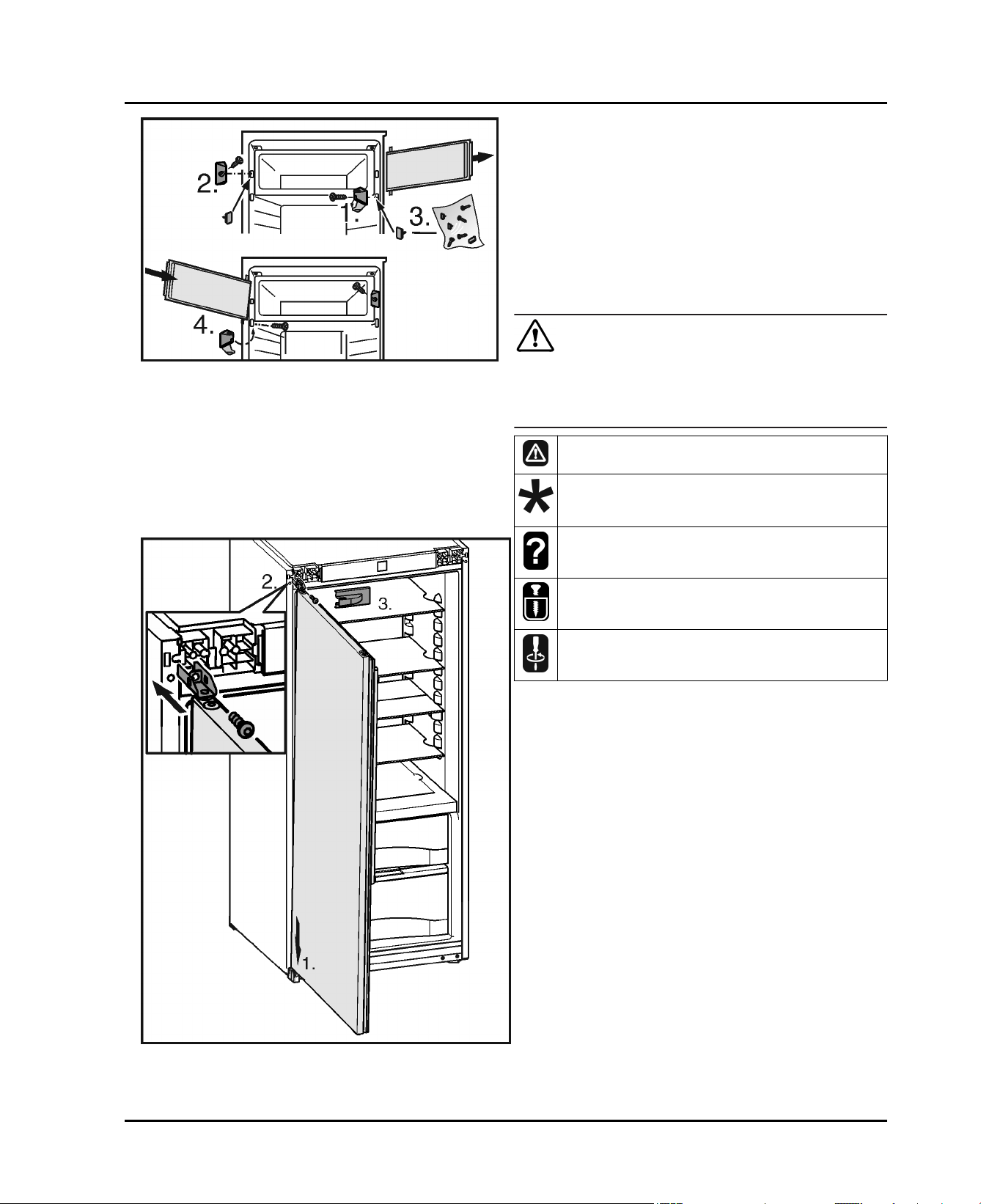
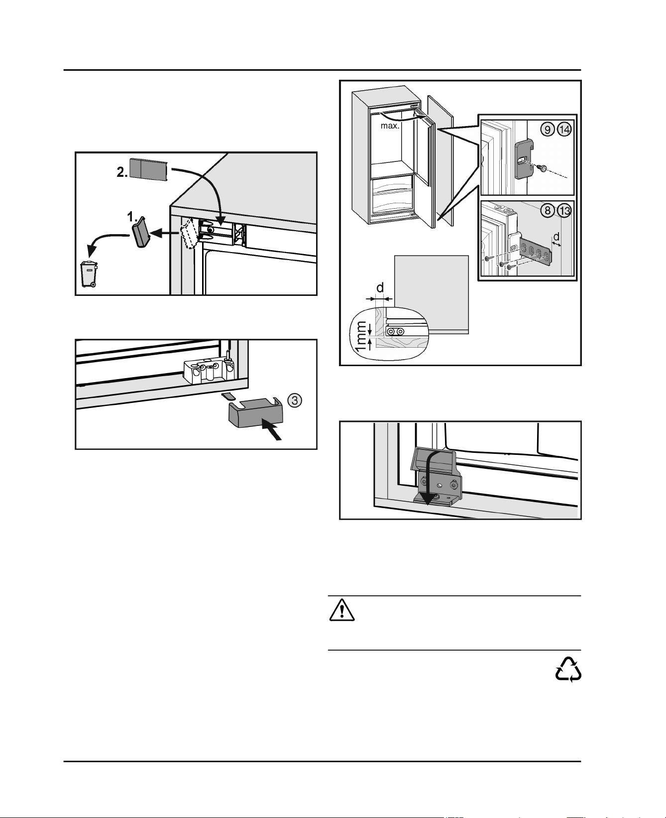
9 Installing the appliance in the recess.
Fig. 13
Remove the compartment door (1). Fold back the cover
u
on the bearing bracket and unscrew and remove the
bearing bracket with the compartment door.
Swap the plug (2).
u
Close off the now unused holes with the supplied plugs
u
(3).
Fit the compartment door (4). Insert the compartment
u
door from above, fit the bearing bracket and close the
cover.
Risk of fire due to short circuit.
u
u
Fitting the door: Position on the bearing brackets at the
bottom (1). Insert the top bearing bracket and tighten
the screw (2).
Fit the covers on the handle side again (3). Only fit the
hinge side cover after installing the appliance into the
cabinet again.
Check all screws and retighten if necessary.
WARNING
When inserting the appliance into the recess do not
squash, jam or damage the power cable.
Do not operate the appliance with a faulty power cable.
There is the risk of injury when doing this. Obey the
safety instructions.
The instructions apply to several models. Only perform
this step if the appliance is fitted with the corresponding
feature.
Select one of the alternatives shown.
Only undo the screw. Don't take it out.
Check the screws and if necessary tighten them.
The following assembly parts are supplied with the appliance:
Fig. 14
8 * Depending on model and options
Page 9
Installing the appliance in the recess.
If the depth of the unit is
less than 21-3/4 in.
(553 mm) remove the
spacers on the back of the
appliance in order to be
able to push the appliance
completely into the recess.
Removing the spacers may
cause the appliance to use
more energy as this
reduces the ventilation
cross-section.
Undo the screw and remove the spacers.
u
Fig. 15
The following tool is also required:
Fig. 17
Remove the mains cable cleat (1) and run the cable
u
upwards using a thread (2).
Push the appliance two thirds into the cabinet (3).
u
Fig. 16
* Depending on model and options 9
Page 10
Installing the appliance in the recess.
Fig. 18
Fit the equalizer trim on top. If the hinge is on the left,
u
slide the equalizer trim into the left hook. If the hinge is
on the right, slide the equalizer trim into the right hook.
Fig. 19
Remove the cover and screw the bracket in.
u
Fig. 20
Fit the strip: place at the top under the bracket and stick
u
to the side panel. The strip must not be shortened.
10 * Depending on model and options
Page 11
Installing the appliance in the recess.
Fig. 21
Push the appliance in until the bracket touches the top
u
on the front of the cabinet side panel (1).
Screw the bearing support in but do not tighten the
u
screws (2).
Check the insertion depth. The front edge of the
u
bearing support must be flush with the front edge of the
cabinet floor.
Fig. 22
Check the insertion depth (A). The distance between
u
the front edge of the cabinet and the appliance body
must be 1-21/32 '' (42 mm). If necessary make allowance for the stops on the cabinet (d).
* Depending on model and options 11
Page 12
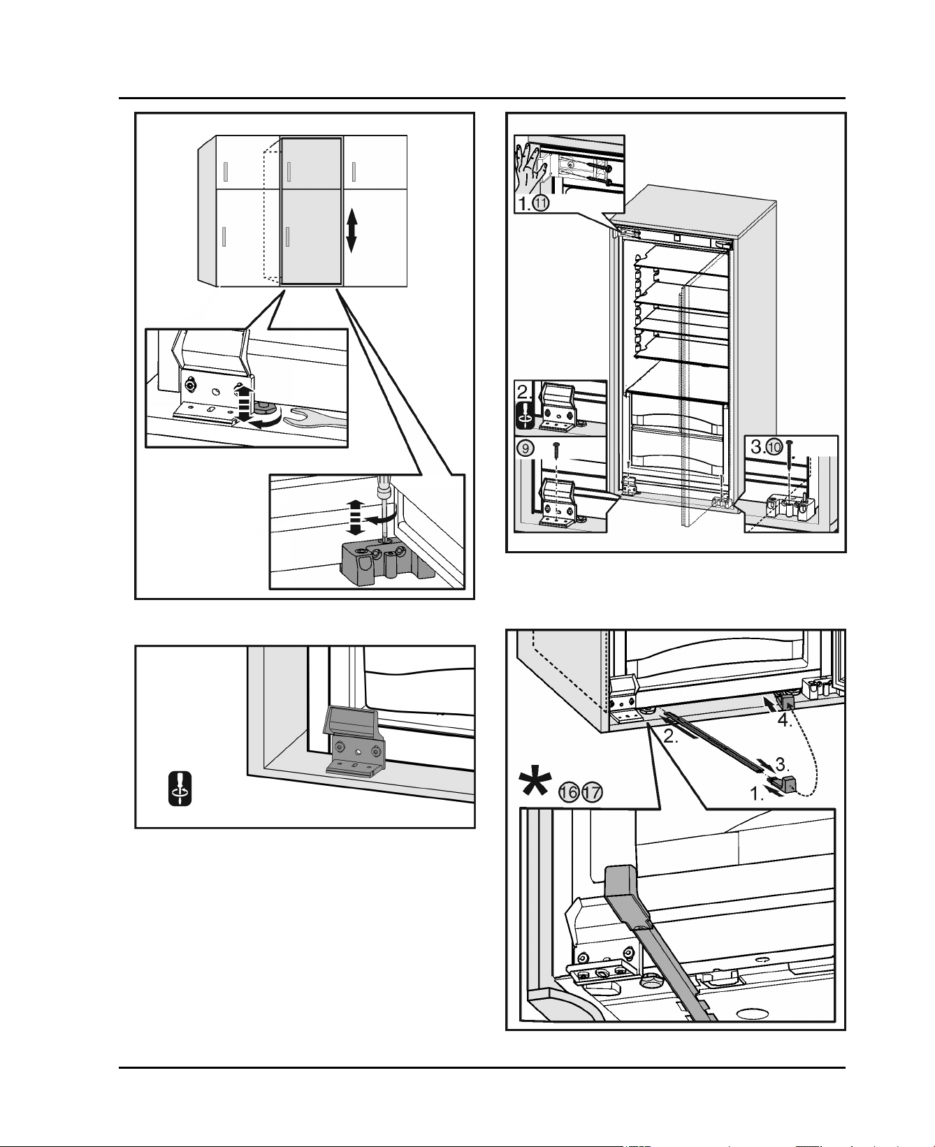
Installing the appliance in the recess.
Fig. 23
Align the height of the appliance with the adjusting feet.
u
Fig. 24
Tighten the screws on the bottom of the bearing
u
support.
Fig. 25
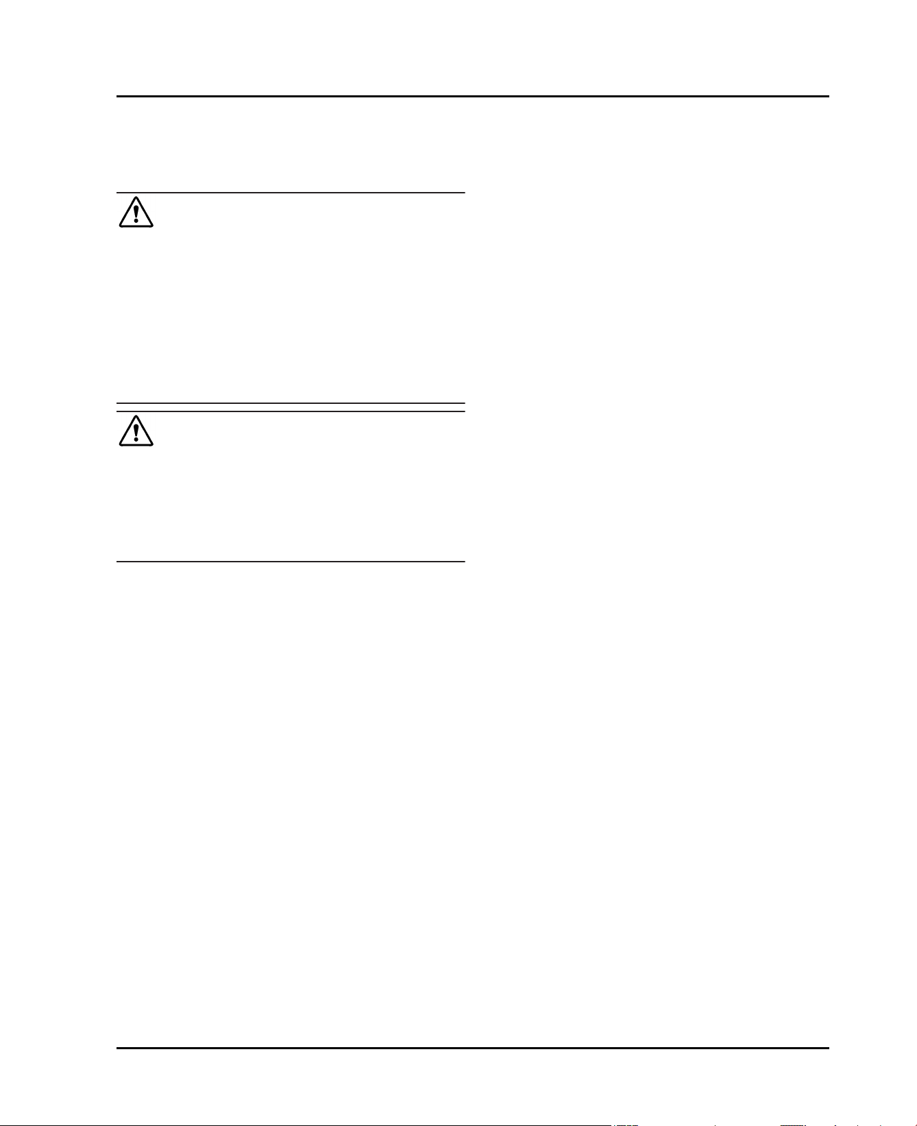
Fix the appliance in the recess, first of all the top handle
u
side then the bottom. Then the hinge side at the
bottom.
Fig. 26
12 * Depending on model and options
Page 13
Supporting the appliance at the bottom at the back:
u
Insert the handle into the stabilization rail and push the
stabilization rail into the appliance floor. Remove the
handle and do the same with the second stabilization
rail.
Check all screws and retighten if necessary.
u
Fig. 27
Remove the stop from the bracket on the handle side
u
and dispose of it. Re-attach cover.
Disposal of packaging
Fig. 28
Fit the bottom cover on the hinge side to the bottom
u
bearing support.
Fig. 29
Attaching the cabinet door to the appliance door: Open
u
the door as wide as it will go. Fit the bracket on the
appliance door and the rail to the cabinet door.
Fig. 30
Fold the bearing support cover on the hinge side down-
u
wards.
10 Disposal of packaging
WARNING
Danger of suffocation from packaging materials and films!
Do not allow children to play with packaging materials.
u
The packaging is made from recyclable materials:
Corrugated card/cardboard
Parts made of foamed polystyrene
Films and bags from polyethylene
Packing bands from polypropylene
Wood frame nailed together with a polyethylene
window*
* Depending on model and options 13
Page 14
Connecting the appliance
Take the packaging material to an official collection
u
point.
11 Connecting the appliance
WARNING
Electrical shock hazard!
Start-up should only take place once the appliance has
u
been installed according to these instructions.
Electrically ground appliance.
u
Do not ground to a gas pipe.
u
Check with a qualified electrician if you are not sure the
u
appliance is properly grounded.
Do not have a fuse in the neutral or grounding circuit.
u
Do not use an extension cord, power bar or a multiple
u
socket adapter.
Do not use a power cord that is frayed or damaged.
u
WARNING
Electrical shock hazard!
This appliance is equipped with a three-prong (grounding)
polarized plug for your protection against possible shock
hazards. Electrical Grounding Required.
Do not remove the round grounding prong from the
u
plug.
Use only an grounded adapter.
u
Wait 1 hour after installation before you plug in the
appliance. This allows the refrigerant and system lubrication to reach equilibrium.
Make sure incoming voltage is the same as the appli-
ance rating. A 110-120 Volt, 60 Hz, 15 Amp electrical
supply (20 Amp for side-by-side installations) circuit
that is controlled by a circuit breaker or fuse is required.
We recommend using a dedicated circuit for this appli-
ance to prevent electrical overload.
Follow all Federal, State and local electrical, fire and
building codes and ordinances when installing the
receptacle and / or the appliance.
In some communities, a wall switch is required to turn
power to the appliance ON and OFF.
To reduce the risk of fire, electric shock, or personal
injury, installation work and electrical wiring must be
done by a qualified electrician in accordance with all
applicable codes and standards, including fire-rated
construction.
The Power Plug must be easily accessible so that the
appliance can be disconnected from the mains quickly
in an emergency. It must not be behind the back of the
appliance.
The top of the electric outlet must be located within
82-5/8 in. (2100 mm) from the top of the base in the
cabinet.
14 * Depending on model and options
Page 15

Instrucciones
de montaje
Frigorífico y congelador,
integrable, puerta orientable
HC700B
020316 7086428 - 00
Page 16

Notas generales sobre seguridad
Contenido
1 Notas generales sobre seguridad................ 16
2 Transporte del aparato.................................. 16
3 Instalación del aparato.................................. 16
4 Medidas del aparato...................................... 18
5 Medidas del habitáculo................................. 18
6 Puerta del mueble.......................................... 18
7 Ventilación y salida de aire del mueble de
cocina............................................................. 20
8 Cambiar el tope de puerta............................ 21
9 Instalar el aparato en el habitáculo............. 22
10 Eliminación del embalaje.............................. 27
11 Conexión del aparato.................................... 28
El fabricante trabaja continuamente para seguir desarrollando todos los tipos y modelos. Por lo tanto, agradeceríamos su comprensión ante posibles modificaciones de
la forma, el equipo y la técnica.
Para conocer todas las ventajas de su nuevo aparato, lea
detenidamente las indicaciones de este manual.
Las instrucciones son válidas para varios modelos;
pueden producirse variaciones. Las secciones que sólo
se refieren a determinados aparatos aparecen marcadas
con un asterisco (*).
Las instrucciones de procedimiento aparecen
marcadas con un
aparecen marcados con un .
, los resultados de procedimiento
1 Notas generales sobre seguridad
“Medidas del habitáculo”
(consulte 5) y el “Venti-
lación y salida de aire del mueble de cocina”
(consulte 7) .
-
La caja de enchufe debe ser fácilmente accesible para poder desconectar el aparato rápidamente de la toma de corriente en caso de
emergencia. Se debe encontrar fuera del área
de la parte trasera del aparato.
PELIGRO identifica una situación de peligro
inminente que, si no se evita, puede
producir lesiones graves o incluso la
muerte.
ADVERTENCIA
ATENCIÓN identifica una situación de peligro
AVISO identifica una situación de peligro
Nota identifica indicaciones y recomen-
identifica una situación de peligro
que, si no se evita, puede producir
lesiones graves o incluso la muerte.
que, si no se evita, puede producir
lesiones leves o moderadas.
que, si no se evita, puede producir
daños materiales.
daciones útiles.
2 Transporte del aparato
ATENCIÓN
Riesgo de daños y lesiones derivado de un transporte
inadecuado
Transporte el aparato embalado.
u
Transporte el aparato en posición vertical.
u
No transporte el aparato solo.
u
-
Lea y siga estas instrucciones. pues contienen
indicaciones sobre la seguridad que son
3 Instalación del aparato
importantes para una instalación y un funcionamiento perfectos. Lea y siga siempre las
indicaciones sobre la seguridad
-
Es importante que se sigan las directrices e
indicaciones de estas instrucciones para que
el aparato se instale y funcione correctamente.
Lea y comprenda toda la información que
figura en estas instrucciones antes de instalar
el aparato.
-
Peligro de asfixia y aplastamiento:
Retire las puertas y baldas de los aparatos
antiguos para que no supongan ningún peligro
¡Peligro de incendio a consecuencia de un cortocircuito!
Si los cables de red/conectores del aparato o de otro
aparato entran en contacto con la parte trasera del
mismo, los cables de red/conectores pueden sufrir daños
debido a las vibraciones del aparato y se puede producir
un cortocircuito.
u
u
ADVERTENCIA
Coloque el aparato de tal forma que no entre en
contacto con ningún conector o cable de red.
No conecte el aparato ni otros aparatos en cajas de
enchufe situadas en el área de la parte trasera del
aparato.
para los niños que estén jugando.
-
Instale, conecte y deseche el aparato
siguiendo estrictamente las indicaciones. En
particular, se deben tener en cuenta el
16 * según modelo y dotación
Page 17

ADVERTENCIA
Riesgo de incendio derivado de la humedad
Si las piezas conductoras de electricidad o la línea de
alimentación eléctrica se humedecen, puede producirse
un cortocircuito.
El aparato está diseñado para utilizarse en espacios
u
cerrados. No ponga en funcionamiento el aparato en
un lugar al aire libre, expuesto a la humedad ni a las
salpicaduras de agua.
Utilice el aparato sólo cuando esté instalado.
u
ADVERTENCIA
Riesgo de incendio derivado del refrigerante
El refrigerante R 600a contenido es respetuoso con el
medioambiente pero inflamable. Las salpicaduras de
refrigerante pueden inflamarse.
No dañe las tuberías del circuito frigorífico.
u
ADVERTENCIA
Peligro de incendio y de sobrecalentamiento
No coloque aparatos que emiten calor como, por ej.
u
microondas, tostadoras etc. sobre el aparato.
AVISO
Riesgo de daños derivado de agua de condensación
No instale el aparato directamente junto a otro frigorí-
u
fico/congelador.
AVISO
¡Existe riesgo de que el suelo del mueble sufra daños!
Proteja el suelo cubriéndolo antes de retirar el emba-
u
laje del aparato.
ADVERTENCIA
Peligro de daños por sobrecalentamiento, limitaciones
funcionales.
Mantener libres de obstrucciones las aberturas de
u
ventilación, en la envolvente del aparato o en la estructura empotrable.
Instalación del aparato
No coloque solo el aparato, sino con dos o más
q
personas.
Cuanto más refrigerante R 600a haya en el aparato,
q
más grande deberá ser el recinto en el que se
encuentre el aparato. En recintos demasiado pequeños
se puede formar una mezcla inflamable de gas y aire al
producirse una fuga. Por cada 0.39 oz (11 g) de refrigerante R 600a, el lugar de instalación debe tener al
menos 35.5 ft3 (1 m3) según la norma EN 378. La
cantidad de refrigerante de su aparato figura en la
placa de identificación situada en el interior del
aparato.
Si el aparato se instala en un entorno muy húmedo, en
q
la parte exterior del aparato se puede formar agua de
condensación. Preste siempre atención a que exista
una buena ventilación y escape de aire en el lugar de
instalación.
La capacidad de carga del suelo debe admitir el peso
q
del aparato, además de aprox. 1200 pounds (544 kg)
correspondientes al peso de los alimentos.
La caja de enchufe eléctrico debe estar en la debida
q
posición y el fusible ha de ser el correcto.
No limite la ventilación ni la salida de aire. Para el
q
funcionamiento del aparato, es necesario disponer de
suficiente ventilación y salida de aire. La rejilla de aire
disponible en el lado de operación proporciona una
sección de ventilación adecuada en el aparato de
31 in.2 (200 cm2). En caso de sustituir la rejilla de aire
por un panel, éste debe tener una sección de ventilación del mismo tamaño, como mínimo, o mayor que la
rejilla del fabricante.
Anote el tipo (modelo, número), la denominación del
u
aparato, el número de serie/aparato, la fecha de
compra y la dirección del distribuidor en los campos
correspondientes del manual de uso y cuidado.
Retire todos los materiales de la parte trasera o de las
u
paredes laterales del aparato que puedan obstaculizar
la correcta instalación o ventilación y salida de aire.
Después del montaje:
Retire las láminas protectoras, cintas adhesivas y
u
piezas de protección para el transporte, etc.
Nota
Limpie el aparato (consulte las instrucciones de
u
manejo, capítulo "Limpiar el aparato").
ADVERTENCIA
Peligro de vuelco
Con el fin de evitar peligros a causa de la inestabilidad
u
del aparato, éste se debe fijar según las instrucciones.
Permita que un profesional se encargue del montaje
q
del aparato en el mueble de cocina.
Si existe algún daño en el aparato, consulte de inme-
q
diato - antes de conectarlo - al proveedor.
El suelo del lugar de instalación debe ser horizontal y
q
liso.
No coloque el aparato en una zona de radiación solar
q
directa, ni junto a la cocina, la calefacción o similares.
* según modelo y dotación 17
Page 18

Medidas del aparato
4 Medidas del aparato
Fig. 2
Fig. 1
pulgadas mm
A
C
C
21 1/4 pulg. 540 mm
21 7/16 pulg. 544 mm
47 15/16 pulg. 1218 mm
5 Medidas del habitáculo
El aparato es empotrable y, por lo tanto, se puede integrar
completamente en un mueble de cocina. El mueble de
cocina correspondiente debe tener las medidas de
montaje especificadas y disponer de suficiente ventilación y escape de aire para garantizar el correcto funcionamiento del aparato.
pulgadas mm
D
E
F
G
H
J
El consumo de energía declarado se ha calculado con
una profundidad de mueble de cocina de 560 mm. El
aparato funciona perfectamente con una profundidad de
mueble de cocina de 550 mm, pero su consumo de
energía es ligeramente superior.
Compruebe el grosor de pared del mueble contiguo:
u
debe ser de como mín. 16 mm.
Instale el aparato únicamente en muebles de cocina
u
estables. Proteja los muebles contra vuelco.
Alinee el mueble de cocina con un nivel de burbuja y
u
una escuadra y, si es necesario, equilíbrelo utilizando
suplementos.
Asegúrese de que el suelo forme un ángulo recto con
u
las paredes laterales del mueble.
48 — 48 5/8 1220 — 1236
22 — 22 3/4 560 — 578
Mín. 21 5/8, se reco-
mienda 22
Mín. 19 11/16 Mín. 500
Mín. 1 5/8 Mín. 40
Máx. 3/4 Máx. 19
Mín. 550, se reco-
mienda 560
6 Puerta del mueble
Para el mueble de cocina se necesita una puerta.
La puerta debe tener un grosor mínimo de 5/8 in.
(16 mm) y máximo de 3/4 in. (19 mm).
Debe haber una ranura de como mínimo 1/8 in. (3 mm)
de anchura entre la puerta y la puerta del armario
situada encima (si existe).
18 * según modelo y dotación
Page 19

Puerta del mueble
La anchura de la puerta del mueble depende del estilo
de la cocina y del tamaño de la ranura entre los
paneles de la puerta del armario. En términos generales, se debe dejar una ranura vertical de 1/8 in.
(3 mm) entre las puertas del mueble.
Si hay disponibles otros armarios, el canto superior de
la puerta del mueble debe estar alineado con las
puertas de los muebles contiguos.
La puerta del mueble debe ser plana y se ha de montar
sin tensión.
Fig. 3
* según modelo y dotación 19
Page 20

Ventilación y salida de aire del mueble de cocina
La altura total del armario (es decir, 49 7/16 in.
(1256 mm)) más el grosor de la tapa y la base
(normalmente de 3/4 in. (19 mm)): 70 3/8 in. + 3/4 in. +
3/4 in. = 47 15/16 in. ( 1218 mm + 19 mm + 19 mm =
1256 mm )
Fig. 3 (a)
7 Ventilación y salida de aire del mueble de cocina
Fig. 4
Debe haber disponible una sección de ventilación
adecuada de al menos 31 in2 (200 cm2) por cada
aparato en la toma de aire
Básicamente se aplica lo siguiente: cuanto mayor sea
la sección de ventilación, más energía ahorrará el
aparato en funcionamiento.
La profundidad de la cámara de ventilación en la pared
trasera del mueble debe ser de como mín. 1-1/2 in.
(40 mm).
(A)
y la toma de aire
(B)
Fig. 5
.
Fig. 6
En lugar de montar la sección de ventilación superior
directamente sobre el aparato con una rejilla de aire
opcional
sobre el mueble
del aire en un falso techo
20 * según modelo y dotación
Fig. 6 (C)
Fig. 6 (D)
, se puede instalar cerca del techo
o como rejilla para la salida
Fig. 6 (E)
.
Page 21

8 Cambiar el tope de puerta
Herramientas necesarias:
Fig. 7
ADVERTENCIA
¡Peligro de lesiones al caerse la puerta!
Si las piezas de fijación no están suficientemente atornilladas, la puerta se puede caer. Esto puede causar
lesiones graves. Además, puede ocurrir que la puerta no
cierre y el aparato no refrigere correctamente.
Atornille los soportes de cojinete en las partes superior
u
e inferior (con 4 Nm) para fijarlos.
Cambiar el tope de puerta
Fig. 8
Desmonte las cubiertas. Dado el caso, utilice un
u
destornillador para tornillos de cabeza ranurada.
Fig. 9
Fig. 10
Retirar la puerta: desenrosque el tornillo (1) y retire la
u
puerta con la pieza de cojinete (2).
Fig. 11
Cambie de sitio la pieza de cojinete.
u
Fig. 12
Cambie de sitio el soporte de cojinete inferior.
u
* según modelo y dotación 21
Page 22

Instalar el aparato en el habitáculo
Montar la puerta: colóquela en la parte inferior sobre el
u
perno de cojinete (1). Introduzca el perno de cojinete
superior y apriete el tornillo (2).
Vuelva a montar las cubiertas en el lado del tirador (3).
u
Vuelva a montar la cubierta en el lado de la bisagra
después del montaje en el mueble.
Compruebe y, dado el caso, vuelva a apretar todos los
u
tornillos.
9 Instalar el aparato en el habitáculo
Fig. 13
Retirar la puerta del compartimiento (1): pliegue la
u
cubierta en el soporte de cojinete y desatornille el
soporte de cojinete con la puerta del compartimiento.
Cambie de sitio la pieza de cierre (2).
u
Cierre los agujeros desocupados con los tapones (3)
u
adjuntos.
Montar la puerta del compartimiento (4): inserte la
u
puerta del compartimiento en la parte superior, monte
el soporte de cojinete y cierre la cubierta.
ADVERTENCIA
¡Peligro de incendio a consecuencia de un cortocircuito!
Al introducir el aparato en el habitáculo, no aplaste,
u
aprisione ni dañe la línea de alimentación eléctrica.
No utilice el aparato con una línea de alimentación
u
eléctrica defectuosa.
En este paso existe peligro de lesiones. Tenga en
cuenta las indicaciones sobre la seguridad.
Las instrucciones son válidas para varios modelos.
Realice este paso únicamente si el aparato está equipado con la función correspondiente.
Elija entre las alternativas presentadas.
Suelte sólo los tornillos, no los desenrosque.
Compruebe el atornillamiento y, dado el caso, vuelva a
apretar los tornillos.
Con el aparato se suministran las siguientes piezas de
montaje:
Fig. 14
22 * según modelo y dotación
Page 23

Instalar el aparato en el habitáculo
Con una profundidad de
mueble inferior a
21-3/4 in. (553 mm) ,
desmonte los distanciadores en la parte trasera
del aparato para poder
introducirlo por completo
en el habitáculo. La retirada
de los distanciadores
puede provocar un mayor
consumo de energía, ya
que disminuye la sección
de ventilación.
Suelte el tornillo y retire los distanciadores.
u
Fig. 15
Además, se necesitan las siguientes herramientas:
Fig. 17
Retire el soporte de cable de red (1) e instale el cable
u
de red hacia arriba con la ayuda de un hilo (2).
Introduzca el aparato hasta dos tercios en el mueble
u
(3).
Fig. 16
* según modelo y dotación 23
Page 24

Instalar el aparato en el habitáculo
Fig. 18
Monte el panel de compensación superior. Si la bisagra
u
se encuentra a la izquierda, inserte el panel de
compensación en los ganchos izquierdos. Si la bisagra
se encuentra a la derecha, inserte el panel de compensación en los ganchos derechos.
Fig. 19
Retire la cubierta y atornille la escuadra.
u
Fig. 20
Montar el burlete: colóquelo en la parte superior por
u
debajo de la escuadra y péguelo en la pared lateral. No
se debe acortar el burlete.
24 * según modelo y dotación
Page 25

Instalar el aparato en el habitáculo
Fig. 21
Introduzca el aparato hasta que la escuadra superior
u
alcance la parte delantera de la pared lateral del
mueble (1).
Atornille el soporte de cojinete sin apretar todavía los
u
tornillos (2).
Comprobar la profundidad de inserción: el canto delan-
u
tero del soporte de cojinete debe quedar enrasado con
el canto delantero de la base del mueble.
Fig. 22
Comprobar la profundidad de inserción (A): la distancia
u
desde el canto delantero del mueble hasta el cuerpo
del aparato debe ser de 1-21/32 '' (42 mm) en todo el
perímetro. Dado el caso, tenga en cuenta las piezas de
tope del mueble (d).
* según modelo y dotación 25
Page 26

Instalar el aparato en el habitáculo
Fig. 23
Alinee el aparato en cuanto a altura con las patas de
u
ajuste.
Fig. 24
Apriete los tornillos en el soporte de cojinete inferior.
u
Fig. 25
Fije el aparato en el habitáculo, primero en el lado del
u
tirador superior y luego en el inferior. A continuación,
en la parte inferior en el lado de la bisagra.
Fig. 26
26 * según modelo y dotación
Page 27

Apoyar el aparato en la parte inferior trasera: coloque el
u
tirador en el riel estabilizador e introduzca dicho riel en
el fondo del aparato. Retire el tirador y proceda de la
misma manera con el segundo riel estabilizador.
Compruebe y, dado el caso, vuelva a apretar todos los
u
tornillos.
Fig. 27
Saque el tope de la escuadra en el lado del tirador
u
superior y deséchelo. Vuelva a montar la cubierta.
Eliminación del embalaje
Fig. 28
Monte la cubierta en el soporte de cojinete inferior en el
u
lado de bisagra inferior.
Fig. 29
Unir la puerta del mueble con la del aparato: abra la
u
puerta al máximo. Monte la escuadra en la puerta del
aparato y el riel en la puerta del mueble.
Fig. 30
Pliegue hacia abajo la cubierta del soporte de cojinete
u
en el lado de la bisagra inferior.
10 Eliminación del embalaje
ADVERTENCIA
Peligro de asfixia derivado del material de embalaje y las
láminas
No permita que los niños jueguen con el material de
u
embalaje.
El embalaje está fabricado con materiales reciclables:
Cartón paja/cartón
Piezas de poliestireno expandido
Láminas y bolsa de polietileno
Flejes para bandaje de polipropileno
-
* según modelo y dotación 27
Page 28

Conexión del aparato
Marco de madera clavado con plancha de polie-
tileno*
Deposite el material de embalaje en un punto de reco-
u
gida oficial.
11 Conexión del aparato
ADVERTENCIA
¡Peligro de descarga eléctrica!
El aparato ha de ponerse en funcionamiento después
u
de instalarlo conforme a las instrucciones indicadas
anteriormente.
Conexión a tierra del aparato
u
No conecte a tierra el aparato sobre un tubo de gas.
u
Solicite a un electricista que compruebe la instalación
u
si no tiene la certeza de que el aparato se ha conectado a tierra conforme a las especificaciones.
En el circuito eléctrico del conductor neutro o en la
u
conexión toma a tierra no debe montarse ningún
fusible.
No utilice ningún cable prolongador ni tomas de
u
corriente de vías múltiples.
No utilice ningún cable de alimentación eléctrica
u
gastado o dañado.
Para reducir el riesgo de incendio, descarga eléctrica u
otros daños, la instalación y la conexión del aparato
deben realizarse a cargo de un electricista conforme a
las disposiciones y normas competentes, incluidas las
disposiciones relativas a la protección contra incendios.
La caja de enchufe debe ser fácilmente accesible para
poder desconectar el aparato rápidamente de la toma
de corriente en caso de emergencia. Se debe encontrar fuera del área de la parte trasera del aparato.
La toma de corriente debe disponerse de forma que su
borde superior se encuentre a una distancia máxima
de 82-5/8 pulg (2100 mm) del borde superior de la
placa base del mueble de cocina.
ADVERTENCIA
¡Peligro de descarga eléctrica!
Como medida de protección contra descargas eléctricas,
este aparato está equipado con un enchufe trifásico a
prueba de polarización inversa. La toma de corriente
debe estar conectada a tierra debidamente.
No retire las clavijas redondas de la toma de conexión
u
a tierra del conector.
Utilice únicamente un adaptador para cajas de enchufe
u
con conexión a tierra.
Espere 1 hora después de la instalación para conectar
el aparato a la red eléctrica. De este modo puede distribuirse el refrigerante y el aceite de la máquina frigorífica conforme a las especificaciones.
Asegúrese de que la tensión de la red eléctrica coin-
cide con la tensión de conexión del aparato. Para
utilizar el aparato es necesario disponer de un suministro eléctrico de 110 - 120 voltios, a 60 Hz y 15 amperios (20 amperios en el montaje Side-by-Side) que ha
de estar protegido mediante un interruptor principal o
un fusible.
El fabricante recomienda utilizar el aparato en un
circuito independiente para evitar la sobrecarga eléctrica.
Al instalar la toma de corriente y/o el aparato, es
preciso observar todas las disposiciones legales referentes a la instalación electrónica, la protección contra
incendios y las normas de montaje.
En determinados países es obligatorio conectar el
aparato al suministro eléctrico mediante un interruptor
de entrada/salida (EIN/AUS) montado en la pared.
28 * según modelo y dotación
Page 29

Instructions
de montage
Congélateurs et réfrigérateurs,
intégrables, porte oscillante
HC700B
020316 7086428 - 00
Page 30

Consignes de sécurité générales
Sommaire
1 Consignes de sécurité générales................ 30
2 Transport de l'appareil.................................. 30
3 Mise en place de l'appareil........................... 30
4 Dimensions de l'appareil.............................. 32
5 Dimensions de la niche................................. 32
6 Porte de meuble............................................. 32
7 Aération et ventilation de l'élément de
cuisine............................................................ 34
8 Changer le sens de la porte.......................... 35
9 Installer l'appareil dans la niche.................. 36
10 Eliminer l'emballage...................................... 41
11 Brancher l'appareil........................................ 42
Le fabricant travaille constamment au développement de
tous les types et modèles d'appareils.C'est pourquoi nous
nous réservons le droit de modifier la forme, l'équipement
et la technique de nos appareils. Nous vous remercions
de votre compréhension.
Afin de découvrir tous les avantages de votre nouvel
appareil, nous vous prions de lire attentivement ces
instructions de montage.
Ces instructions de montage sont valables pour plusieurs
modèles, des différences sont donc possibles.Les paragraphes ne concernant que certains appareils sont indiqués par un astérisque (*).
Les instructions de manipulation sont indiqués par
, les résultats de manipulation par un .
un
-
Installer, raccorder et éliminer l'appareil
uniquement selon les indications mentionnées
dans les instructions. Respecter en particulier
les chapitres « Dimensions de la niche » (voir 5)
et « Aération et ventilation de l'élément de
cuisine » (voir 7) .
-
La prise de courant doit être bien accessible
afin de pouvoir débrancher rapidement l'appareil en cas d'urgence. Elle doit se situer en
dehors de la partie arrière de l´appareil.
DANGER indique une situation dangereuse
imminente entraînant la mort ou des
blessures corporelles graves si elle
n'est pas évitée.
AVERTISSEMENT
ATTENTION indique une situation dangereuse
ATTENTION indique une situation dangereuse
Remarque indique les remarques et conseils
indique une situation dangereuse
susceptible d'entraîner la mort ou
des blessures corporelles graves si
elle n'est pas évitée.
susceptible d'entraîner des blessures corporelles moyennes ou
légères si elle n'est pas évitée.
susceptible d'entraîner des
dommages matériels si elle n'est
pas évitée.
utiles.
2 Transport de l'appareil
1 Consignes de sécurité générales
-
Lire et respecter les instructions suivantes.
Elles contiennent des consignes de sécurité
Risque de blessure et d'endommagement dû à un transport incorrect !
u
u
u
ATTENTION
Transporter l'appareil emballé.
Transporter l'appareil debout.
Ne pas transporter l'appareil seul.
importantes pour une installation et un fonctionnement sûrs et parfaits de votre appareil.
Lisez et respectez toujours ces consignes de
3 Mise en place de l'appareil
sécurité !
-
Il est important de respecter les directives et
consignes de ces instructions afin d'assurer
l'installation et le fonctionnement corrects de
l'appareil. Lisez et comprenez toutes les informations de ces instructions avant d'installer
l'appareil.
-
Risque d'asphyxie et d'écrasement :
Retirez les portes et les surfaces de rangement des appareils usagés afin qu'ils ne représentent pas une source de danger pour les
Danger de brûlures par court-circuit!
Lorsque les câbles de raccord / fiches de l´appareil se
trouvent en contact avec la partie arrière d´un autre appareil, ils peuvent être endommagés à cause des vibrations
de l´appareil et par la suite causer un court-circuit.
u
u
AVERTISSEMENT
Placer l'appareil de façon à ce qu'il n'y ait pas de
contact avec la fiche ou le câble d´alimentation.
Ne pas brancher d´appareils ni autres dispositifs sur les
prises de courant situées sur la partie arrière de l´appareil.
enfants.
30 * selon le modèle et l‘équipement
Page 31

AVERTISSEMENT
Risque d'incendie dû à l'humidité !
Lorsque des pièces sous tension ou le câble de raccordement au secteur deviennent humides, un court-circuit peut
se produire.
L'appareil a été conçu pour être placé dans des locaux
u
fermés. Ne pas exploiter l'appareil dehors ou dans des
endroits humides non à l'abri de projections d'eau.
Uniquement exploiter l'appareil à l'état monté.
u
AVERTISSEMENT
Risque d'incendie dû au fluide réfrigérant !
Le fluide réfrigérant R 600a contenu dans l'appareil ne
présente aucun danger pour l'environnement mais est
inflammable.En cas de fuite, le fluide réfrigérant risque de
s'enflammer.
Veiller à ne pas endommager les tubes du circuit frigori-
u
fique.
AVERTISSEMENT
Risque d'endommagement et d'incendie !
Ne pas placer un appareil diffusant de la chaleur (p.ex.
u
four à micro-ondes, grille-pain, etc.) sur l'appareil !
ATTENTION
Risque d'endommagement dû à l'eau de condensation !
Ne pas placer l'appareil directement à côté d'un autre
u
réfrigérateur/congélateur.
ATTENTION
Risque de dommage pour le sol!
Protéger le sol en le couvrant avant de retirer les maté-
u
riaux d'emballage de l’appareil.
AVERTISSEMENT
Risque d'endommagement dû à la surchauffe, limitation
du fonctionnement !
Les prises d’air de l’enceinte de l’appareil ou de la
u
structure encastré doivent être dégagées en tout
temps.
Mise en place de l'appareil
Ne pas placer l'appareil dans une zone à ensoleille-
q
ment direct, à côté d'une cuisinière, d'un chauffage ou
équivalents.
Ne pas installer l'appareil seul, de préférence à deux
q
personnes ou plus.
Plus l'appareil contient de réfrigérant R 600a, plus
q
grand doit être le local dans lequel il se trouve. Dans de
petits locaux, une fuite pourrait entraîner la formation
d'un mélange gaz-air combustible. Selon la norme EN
378, le local d'installation doit être par 0.39 oz (11 g) de
réfrigérant R 600a d'au moins 35.5 ft3 (1 m3) . La quantité de réfrigérant de votre appareil figure sur la plaque
signalétique à l'intérieur de l'appareil.
Du condensat peut se former sur la paroi extérieure de
q
l'appareil si celui-ci est placé dans un environnement
très humide. Toujours veiller à une bonne ventilation et
une bonne aération sur le lieu d'emplacement.
La capacité portante du sol doit suffire pour le poids de
q
l'appareil plus environ 1200 pounds (544 kg) d'aliments.
La prise de courant électrique doit être placée à la posi-
q
tion réglementaire et le fusible dimensionné exactement.
Ne pas entraver la ventilation et l'aération. Le fonction-
q
nement de l'appareil requiert une ventilation et aération
suffisante. La grille de ventilation prévue d'usine
garantit une section de ventilation efficace sur l'appareil
de 31 in.2 (200 cm2). Si vous remplacez la grille de
ventilation par un panneau, celui-ci doit avoir au moins
une section de ventilation égale ou plus grande que la
grille de ventilation du fabricant.
Noter le type (modèle, numéro), désignation de l'appa-
u
reil, numéro d'appareil/de série, date d'achat et
adresse du distributeur dans les champs prévus à cet
effet dans le manuel Use&Care.
Eliminer tous les matériaux du dos ou des parois laté-
u
rales de l'appareil susceptibles d'entraver l'installation
conforme ou la ventilation et l'aération.
Après le montage :
Enlever les feuilles de protection, les rubans adhésifs et
u
les protections pour le transport, etc.
Remarque
Nettoyer l'appareil (voir mode d'emploi, chapitre
u
"Nettoyer l'appareil").
AVERTISSEMENT
Risque de basculement
Afin d'éviter toute mise en danger due à l'instabilité de
u
l'appareil, celui-ci doit être fixé conformément aux
instructions.
Confier si possible à un spécialiste l'intégration de l'ap-
q
pareil dans l'élément de cuisine.
En cas de dégâts à l'appareil, contactez immédiate-
q
ment le fournisseur avant de brancher l'appareil.
Le sol au lieu d'emplacement doit être horizontal et
q
plan.
* selon le modèle et l‘équipement 31
Page 32

Dimensions de l'appareil
4 Dimensions de l'appareil
Fig. 2
Fig. 1
po. mm
A
B
C
21 1/4 po. 540 mm
21 7/16 po. 544 mm
47 15/16 po. 1218 mm
5 Dimensions de la niche
L'appareil est encastrable et par conséquent, complètement entouré d'un élément de cuisine. L'élément de
cuisine en question doit être réalisé exactement selon les
dimensions d'encastrement données et permettre une
ventilation et une aération suffisante pour qu'un fonctionnement correct de l'appareil soit garanti.
po. mm
D
E
F
G
H
J
La consommation énergétique déclarée a été déterminée
avec une profondeur de meuble de cuisine de 560 mm.
L'appareil est totalement fonctionnel avec une profondeur
de meuble de cuisine de 550 mm, mais sa consommation
énergétique est légèrement supérieure.
L'épaisseur des meubles voisins doit être contrôlée :
u
elle doit être de min. 16 mm.
Installer l'appareil uniquement dans des éléments de
u
cuisine stables, solides. Sécuriser les meubles contre
les chutes.
Ajuster l'élément de cuisine avec un niveau à bulle et
u
une équerre, et si besoin équilibrer avec des cales.
S'assurer que le plancher et les parois latérales du
u
meuble soient positionnés perpendiculairement.
48 — 48 5/8 1220 — 1236
22 — 22 3/4 560 — 578
min. 21 5/8, 22 recom-
mandé
min. 19 11/16 min. 500
min. 1 5/8 min. 40
max. 3/4 max. 19
min. 550, 560 recom-
mandé
6 Porte de meuble
Une porte doit être montée sur le meuble de cuisine.
Cette porte doit avoir une épaisseur minimale de 5/8 in.
(16 mm) et maximale de 3/4 in. (19 mm).
Un espace minimal de 1/8 in. (3 mm) est nécessaire
entre la porte et la porte de l'armoire située au-dessus
(si prévue).
32 * selon le modèle et l‘équipement
Page 33

Porte de meuble
La largeur de la porte du meuble dépend du style de
cuisine et de l'espace entre les panneaux de porte de
l'armoire. En règle générale, un espace vertical de
1/8 in. (3 mm) doit être laissé entre les portes de
meuble.
En présence d'autres armoires, le bord supérieur de la
porte de meuble doit se trouver à la même hauteur que
les portes du meuble voisin.
La porte de meuble doit être plane et être montée sans
contraintes.
Fig. 3
* selon le modèle et l‘équipement 33
Page 34

Aération et ventilation de l'élément de cuisine
Hauteur totale de l'armoire (à savoir, 49 7/16 in.
(1256 mm)) plus l'épaisseur du panneau supérieur et du
panneau inférieur
(19 mm)) : 70 3/8 in. + 3/4 in. + 3/4 in. = 47 15/16 in.
( 1218 mm + 19 mm + 19 mm = 1256 mm )
Fig. 3 (a)
(généralement de 3/4 in.
7 Aération et ventilation de l'élément de cuisine
Fig. 4
Il doit y avoir un espace de ventilation efficace d'au
moins 31 in2 (200 cm2) par appareil au niveau de
l'entrée d'air
En principe s'applique : plus l'espace de ventilation est
grand, moins l'appareil consomme d'énergie.
La profondeur minimale de l'espace de ventilation sur
la paroi arrière du meuble doit être de 1-1/2 in.
(40 mm).
L'espace de ventilation du dessus peut être réalisé
directement au-dessus de l'appareil avec une grille de
ventilation disponible en option
placard
bouche de sortie d'air dans un faux plafond
(A)
et la sortie d'air
Fig. 6 (D)
(B)
.
Fig. 6
Fig. 6 (C)
à proximité du plafond ou comme
, au-dessus du
Fig. 6 (E)
Fig. 5
.
34 * selon le modèle et l‘équipement
Page 35

8 Changer le sens de la porte
Outillage nécessaire :
Fig. 7
AVERTISSEMENT
Risque de blessure si la porte tombe !
Si les éléments de fixation ne sont pas bien vissés, la
porte risque de tomber. Cela peut entraîner de graves
blessures. Par ailleurs, la porte risque de ne pas fermer
correctement et l'appareil de ne pas refroidir convenablement.
Visser les charnières en bas et en haut (avec 4 Nm).
u
Changer le sens de la porte
Fig. 8
Soulever les caches. Utiliser éventuellement un tour-
u
nevis à fente.
Fig. 9
Fig. 10
Déposer la porte : Desserrer la vis (1) et déposer la
u
porte avec la partie de palier (2).
Fig. 11
Permuter l'élément pivotant.
u
Fig. 12
Intervertir le support d'appui inférieur.
u
* selon le modèle et l‘équipement 35
Page 36

Installer l'appareil dans la niche.
Fig. 13
Déposer la porte du compartiment (1) : Relever le
u
cache sur le support d'appui et dévisser le support
d'appui avec la porte du compartiment.
Intervertir le système de fermeture (2).
u
Obturer les orifices libérés à l'aide des bouchons
u
fournis (3).
Monter la porte du compartiment (4) : Mettre en place
u
la porte de compartiment en haut, monter le support
d'appui et rabattre le cache.
Remonter les caches du côté de la poignée (3).
u
Remonter le cache du côté de la charnière seulement
après l'encastrement dans le meuble.
Vérifier toutes les vis, les resserrer si nécessaire.
u
9 Installer l'appareil dans la niche.
AVERTISSEMENT
Risque d'incendie dû à un court-circuit !
Lors de l'insertion de l'appareil dans la niche, ne pas
u
pincer, coincer, ou endommager le cordon d'alimentation.
Ne pas utiliser l'appareil avec un câble de raccord au
u
réseau défectueux.
Lors de cette étape, il y a un risque de blessure !
Respecter les indications de sécurité !
Ce mode d'emploi est valable pour plusieurs modèles.
Exécuter cette étape uniquement si l'appareil est
équipé de la fonction correspondante.
Choisir entre les alternatives représentées.
Uniquement desserrer les vis, ne pas dévisser.
Vérifier le visage et le cas échéant, resserrer.
Les éléments de montage ci-après sont joints à l'appareil :
Fig. 14
Monter la porte : La placer en bas sur l'axe d'appui (1).
u
Insérer l'axe d'appui supérieur et serrer la vis (2).
36 * selon le modèle et l‘équipement
Page 37

Installer l'appareil dans la niche.
En cas de profondeur de
meuble inférieure à
21-3/4 in. (553 mm) ,
démonter les entretoises au
dos de l'appareil, afin de
pouvoir pousser l'appareil
complètement dans la
niche. Enlever les les entretoises peut augmenter la
consommation de courant
étant donné que la section
de ventilation est réduite.
Desserrer la vis et retirer l'entretoise.
u
Fig. 15
L'outillage suivant est en outre nécessaire :
Fig. 17
Enlever l'attache-câble d'alimentation (1) et poser le
u
câble d'alimentation vers le haut à l'aide d'un fil (2).
Pousser l'appareil aux deux tiers dans le meuble (3).
u
Fig. 16
* selon le modèle et l‘équipement 37
Page 38

Installer l'appareil dans la niche.
Fig. 18
Monter la cornière de compensation en haut. Si la char-
u
nière est à gauche, insérer la cornière de compensation dans les crochets gauches. Si la charnière est à
droite, insérer la cornière de compensation dans les
crochets droits.
Fig. 19
Retirer le cache et visser la cornière.
u
Fig. 20
Monter le bourrelet : le placer en haut sous la cornière
u
et le coller à la paroi latérale. Il n'est pas nécessaire de
raccourcir le bourrelet.
38 * selon le modèle et l‘équipement
Page 39

Installer l'appareil dans la niche.
Fig. 21
Introduire l'appareil jusqu'à ce que la cornière bute en
u
haut sur la face avant de la paroi latérale du meuble (1).
Visser le support d'appui mais ne pas serrer les vis (2).
u
Vérifier la profondeur d'insertion : le bord avant du
u
support d'appui doit être aligné sur le bord avant du
plancher du meuble.
Fig. 22
Vérifier la profondeur d'insertion (A) : la distance du
u
bord avant du meuble par rapport au corps de l'appareil
être partout de 1-21/32 '' (42 mm). Tenir éventuellement
compte des butées du meuble (d).
* selon le modèle et l‘équipement 39
Page 40

Installer l'appareil dans la niche.
Fig. 23
Régler l'appareil en hauteur à l'aide des pieds de
u
réglage.
Fig. 24
Visser fermement les vis en bas sur le support d'appui.
u
Fig. 25
Fixer le meuble dans la niche : du côté de la poignée
u
en premier, en bas ensuite. Et pour finir du côté de la
charnière.
Fig. 26
40 * selon le modèle et l‘équipement
Page 41

Etayer l'appareil derrière en bas : enficher la poignée
u
sur le rail de stabilisation et enfoncer ce dernier dans le
plancher de l'appareil. Retirer la poignée et procéder
de la même façon avec le deuxième rail de stabilisation
Vérifier toutes les vis, les resserrer si nécessaire.
u
Fig. 27
Du côté poignée en haut, casser la butée de la cornière
u
et l'éliminer. Replacer le cache.
Eliminer l'emballage
Fig. 28
Du côté charnières en bas, monter le cache sur le
u
support d'appui inférieur.
Fig. 29
Relier la porte de placard avec la porte de l'appareil :
u
ouvrir la porte au maximum. Monter la cornière sur la
porte de l'appareil et le rail sur la porte de placard.
Fig. 30
Rabattre le cache du support d'appui du côté char-
u
nières en bas
10 Eliminer l'emballage
AVERTISSEMENT
Risque d'étouffement avec les films et matériaux d'emballage !
Ne pas laisser les enfants jouer avec les matériaux
u
d'emballage.
L'emballage est fabriqué en matériaux recyclables :
carton ondulé / carton
pièces en polystyrène expansé
films et sachets en polyéthylène
colliers de serrage en polypropylène
-
* selon le modèle et l‘équipement 41
Page 42

Brancher l'appareil
cadres en bois cloués avec plaque de polyéthy-
lène*
Déposer les matériaux d'emballage à un centre officiel
u
de collecte des déchets.
11 Brancher l'appareil
AVERTISSEMENT
Risque de décharge électrique !
L’appareil ne doit être mis en marche qu’après avoir été
u
monté et encastré selon les consignes mentionnées cidessus.
Mise à la terre de l’appareil
u
Ne pas effectuer de mise à la terre de l’appareil au
u
dessus d’une conduite de gaz.
Faites venir un spécialiste si vous n’êtes pas certain de
u
la mise à la terre correcte de l’appareil.
Ne pas intégrer de fusible dans le circuit électrique du
u
conducteur neutre ou de la mise à la terre.
Ne pas utiliser de rallonges ou de multiprises.
u
Ne pas utiliser de câble d’alimentation abrasé ou
u
endommagé.
La mise en place et le branchement de l’appareil
doivent être effectués par un spécialiste, en respectant
l’ensemble des consignes et normes en vigueur ainsi
que les règles en matière de , protection contre les
incendies afin de réduire tout risque d’incendie, de
décharges électriques, d’électrocution ou autres blessures.
La prise de courant doit être bien accessible afin de
pouvoir débrancher rapidement l'appareil en cas d'urgence.Elle doit se situer en dehors de la partie arrière
de l´appareil.
La prise doit être disposée de telle manière que son
arête supérieure se situe à une distance maximale
de82-5/8 pouces (2100 mm) par rapport à l’arête supérieure de la plaque de base du meuble de cuisine.
AVERTISSEMENT
Risque de décharge électrique !
Cet appareil est équipé d’une prise à trois pôles avec
détrompeur pour éviter tout risque décharge électrique.
La prise doit être mise à la terre correctement.
Il est formellement interdit de retirer la broche circulaire
u
de mise à la terre de la prise.
Utilisez exclusivement un adaptateur de prise mis à la
u
terre.
Attendre 1 heure après la mise en place avant de
raccorder l’appareil au réseau électrique. Ceci permet
au fluide réfrigérant et à l’huile réfrigérante de se
répartir correctement.
S’assurer que la tension du réseau électrique corres-
pond à la tension d’alimentation de l'appareil. Pour un
fonctionnement correct de l’appareil, prévoir une
alimentation de 110 - 120 V, 60 Hz (et 15 A (20 A si la
mise en place se fait côte à côte) sécurisé par un
commutateur principal ou un fusible.
Le fabricant conseille d’alimenter l’appareil par un
circuit électrique séparé pour éviter les surcharges
électriques.
Respecter l’ensemble des normes en vigueur pour ce
qui est des installations électriques, de la protection
contre les incendies et du code de construction lors de
la mise en place d’une prise et/ou de l’appareil.
Dans certains pays, le branchement de l’appareil au
réseau électrique doit être fait avec la mise en place
d’un commutateur MARCHE/ARRET installé dans le
mur.
42 * selon le modèle et l‘équipement
Page 43

This page intentionally left blank.
Esta Página intencionadamente se marchó en blanco.
Cette Page a intentionnellement quitté le blanc.
Page 44

For Service in the U.S.:
Liebherr Service Center
Toll Free: 1-866-LIEBHER or 1-866-543-2437
Service-appliances.us@liebherr.com
PlusOne Solutions, Inc.
3501 Quadrangle Blvd, Suite 120
Orlando, FL 32817
For Service in Canada:
Liebherr Service Center
Toll Free: 1-888-LIEBHER or 1-888-543-2437
www.euro-parts.ca
EURO-PARTS CANADA
39822 Belgrave Road
Belgrave, Ontario, N0G 1E0
Phone: (519) 357-3320
Fax: (519) 357-1326
www.liebherr-appliances.com
Part No. 7086428 - 00
 Loading...