

Page 1
Installation
Instructions
For Fully Integrated NoFrost
Combined Refrigerator-Freezers
HC 2060/2061
HCB 2060/2061
7084 349-00
Page 2
I
mportant
Please Read and Follow these
Instructions
These instructions contain Danger, Warning and
Caution notes.
This information is important for safe and efficient
installation and operation.
Always read and comply with all Danger, Warning and
Caution notes!
DANGER!
Dangerindicatesahazardwhich
will cause serious injury or death if
precautions are not followed.
WARNING!
Warning indicates a potentially hazardous
situation which, if not avoided, could result
in death or serious injury.
CAUTION!
Caution indicates a potentially hazardous
situation which, if not avoided, may result
in minor or moderate injury.
Contents Page
Unit dimensions ............................................................. 4
Door swing clearance .................................................... 4
Unit venting .................................................................... 4
Cabinet opening dimensions ......................................... 5
Panel dimensions - framed cabinet design ................... 6
Panel dimensions - frameless cabinet design .............. 7
Mounting the anti tipping device on concrete floors ..... 8
Mounting the anti tipping device on wooden floors ...... 8
Mounting the anti tipping device in cabinets
deeper than 24" ............................................................. 9
Cover strips .................................................................... 9
IceMaker
Safety instructions and warnings ................................ 10
Water connection Requirements ................................. 10
Water connection Adapter ........................................... 10
Connection to the water supply ................................... 11
Leveling the appliance ................................................. 12
Fastening the appliance in the recess
Adjusting the refrigerator door
Adjusting the front of the drawer
Before mounting the door panels ................................ 13
Mounting the attachment brackets onto the
door panels
Mounting the refrigerator door panels
Mounting the freezer drawer panels ............................ 17
Mounting the ventilation grille ...................................... 17
.................................................................. 14
..................................... 12
......................... 12
.................................. 13
.................... 15 -16
IMPORTANT
This indicates information that is especially relevant
to a problem-free installation and operation.
Note to the Installer
It is very important to follow the instructions in the
manual to ensure proper installation and operation of
the unit.
Before installing the unit, be sure to thoroughly read
and understand all of the information in this manual.
R600a Refrigerant
WARNING!
The refrigerant contained within the
appliance R600a is environmentally
friendly, but flammable. Leaking refrigerant
can ignite.
To prevent possible ignition follow
the warnings below:
•
Keep ventilation openings, in
the appliance enclosure or in
the built-in structure, clear of
obstruction.
• Donotdamagetherefrigerant
circuit.
• Anyrepairsandworkontheappliance
should only be performed by the customer
service department.
2
Page 3
S
afety
Disposal of Old Appliance
DANGER!
Risk of child entrapment.
Child entrapment and suffocation are not problems of
the past.
Junked or abandoned refrigerators are still dangerous –
even if they will sit for “just a few days.”
If you are getting rid of your old refrigerator, please follow these instructions to help prevent accidents.
Before you discard old appliances:
• Removethedoors.
• Leavetheshelvesinplacesothatchildren
may not easily climb inside.
• Cutoffthepowercablefromthediscarded
appliance.Discardseparatelyfromtheappli-
ance.
• Besuretofollowyourlocalrequirementsfor
disposal of appliances.
Electrical Safety
Connect this appliance to a 15 amp or 20 amp, 110120 VAC, circuit which is grounded and protected by a
circuit breaker or fuse.
We recommend using a dedicated circuit for this appliance to prevent circuit overload and the chance of
interruption to the appliance.
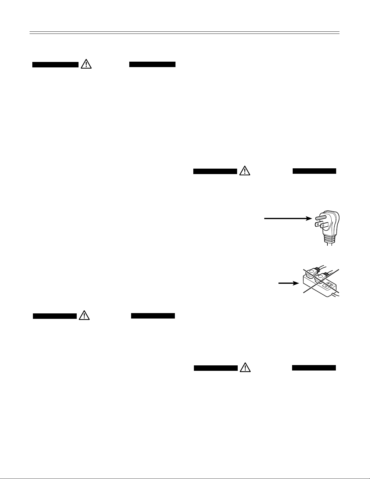
This appliance is equipped with a three-prong (grounding) polarized plug for your protection against possible
shock hazards.
Where a two-prong wall receptacle is encountered,
contact a qualified electrician and have it replaced with
a properly grounded three-prong receptacle in accordance with all local codes and ordinances.
WARNING!
Electrocutionhazard.
Electricalgroundingrequired.
Donotremovetheroundgrounding
•
prong from the plug.
Contact the trash collection agency in
your area for additional information.
Disposal of Carton
The packaging is designed to protect the appliance and
individual components during moving and is made of
recyclable materials.
WARNING!
Keep packaging materials away from
children. Polythene sheets and bags can
cause suffocation!
Please recycle packaging material where facilities are
available.
Donotuseextensioncordsor
•
ungrounded (two prong) adapters.
• Donotuseapowercordthatisfrayedor
damaged.
• Donotuseapowerstrip.
Failure to follow these instructions may
result in fire, electrical shock or death.
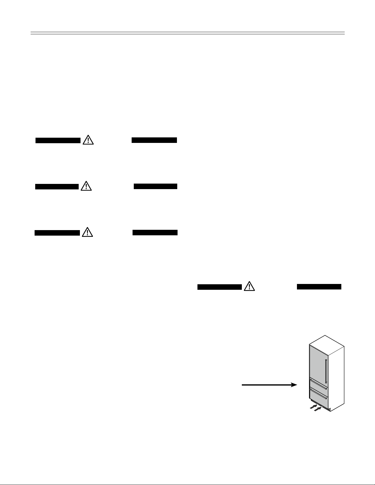
Blocking for Safety
WARNING!
To avoid a hazard due to instability of the
appliance,itmustbefixedinaccordance
with the instructions.
3
Page 4
p
lannIng
I
nformatIon
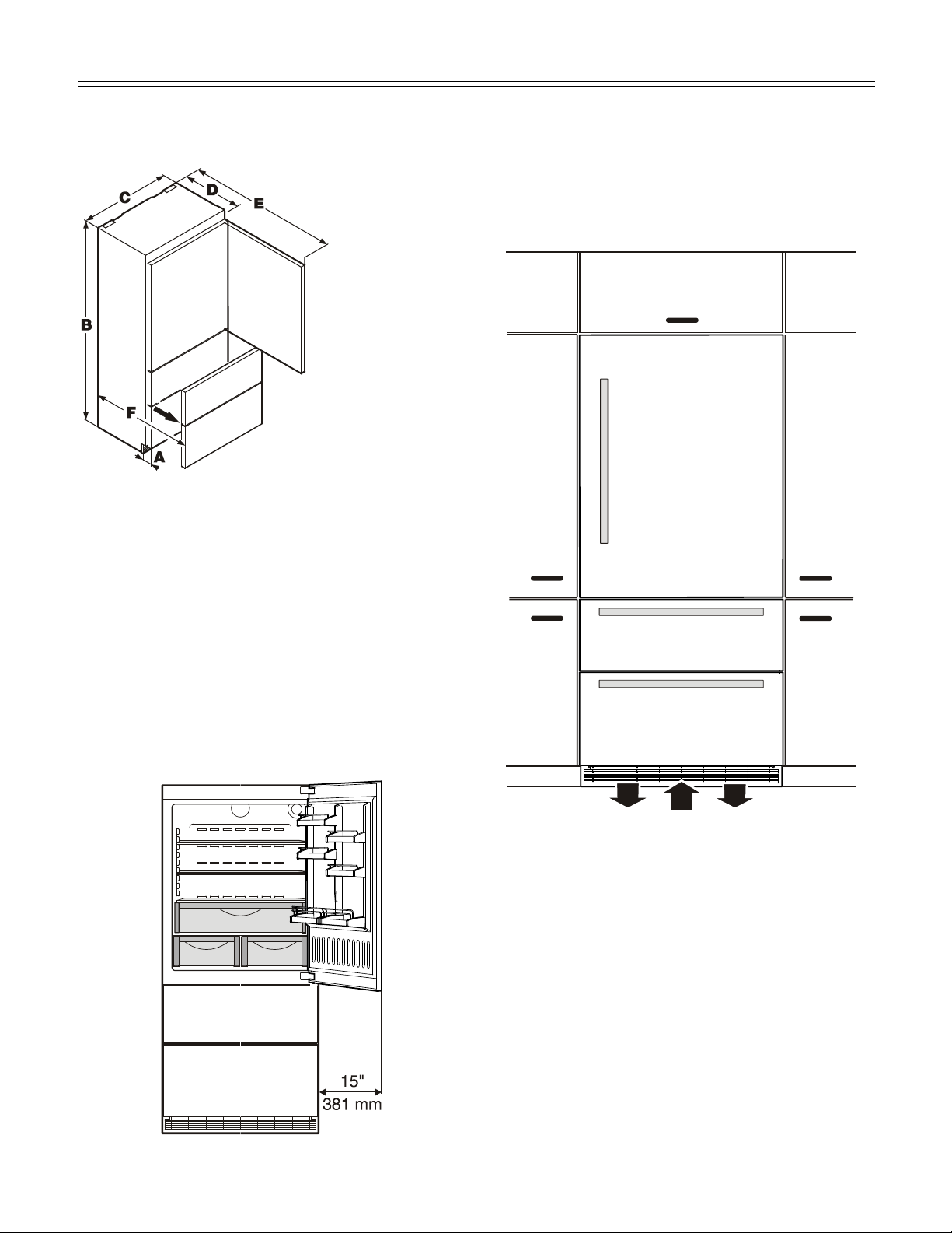
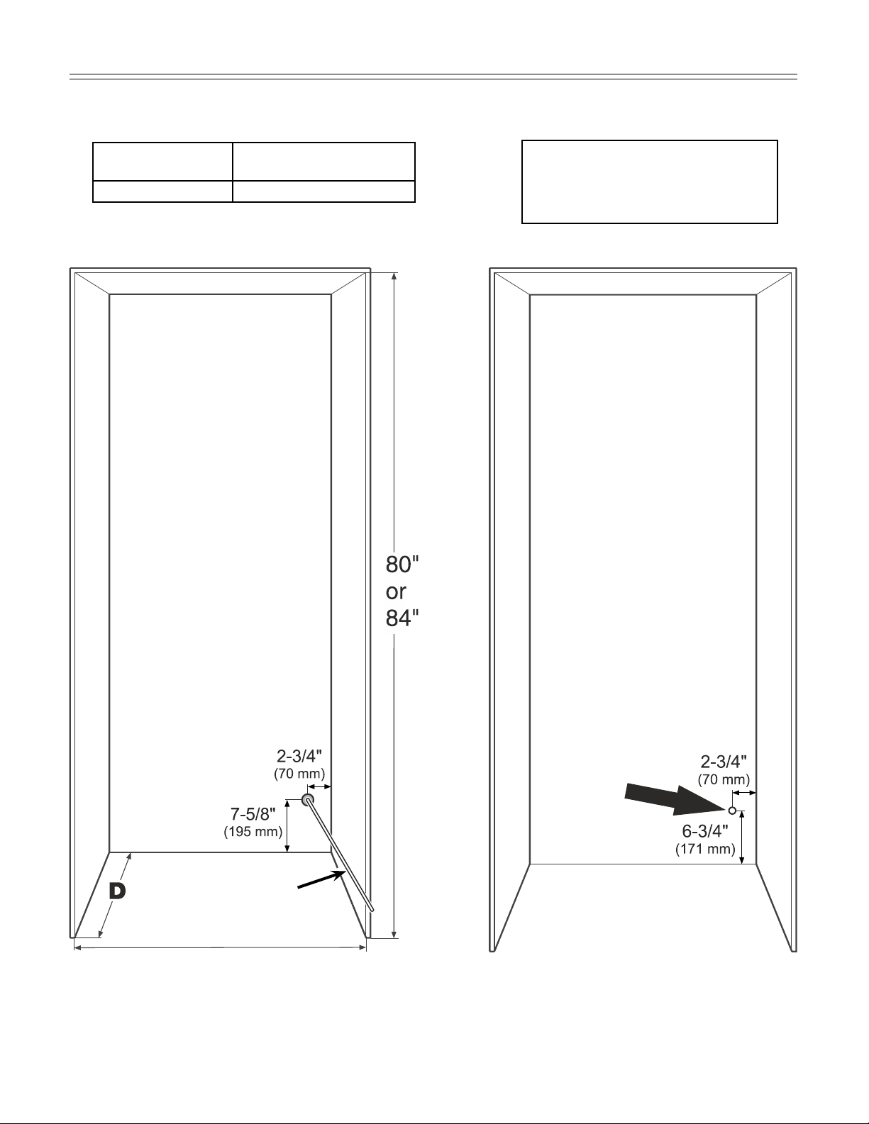
Unit Dimensions - Figure 1
A = 3" (76 mm)
B = 79-13/16" (2027 mm)
C = 35-13/16" (910 mm)
D = 24" (610 mm)
Figure 1
E = 61-1/4" (1556 mm)
F = 37-1/8" (943 mm)
Unit Venting - Figure 3
HC 2060/2061 appliances do not require any ventilation
openings in the cabinet. The required airflow is directed
through the toe kick area.
Door Swing Clearance - Figure 2
Please allow for door swing clearance at locations next
to a wall.
The illustrated measurement is without mounted front
panels. Be sure to add your panel thickness and handle
depth to this measurement in order to avoid interferences.
Figure 3
It is important to use the provided cover grille for the
ventilation opening. This opening must not be covered
with a cabinet base.
Figure 2
4
Page 5
p
lannIng
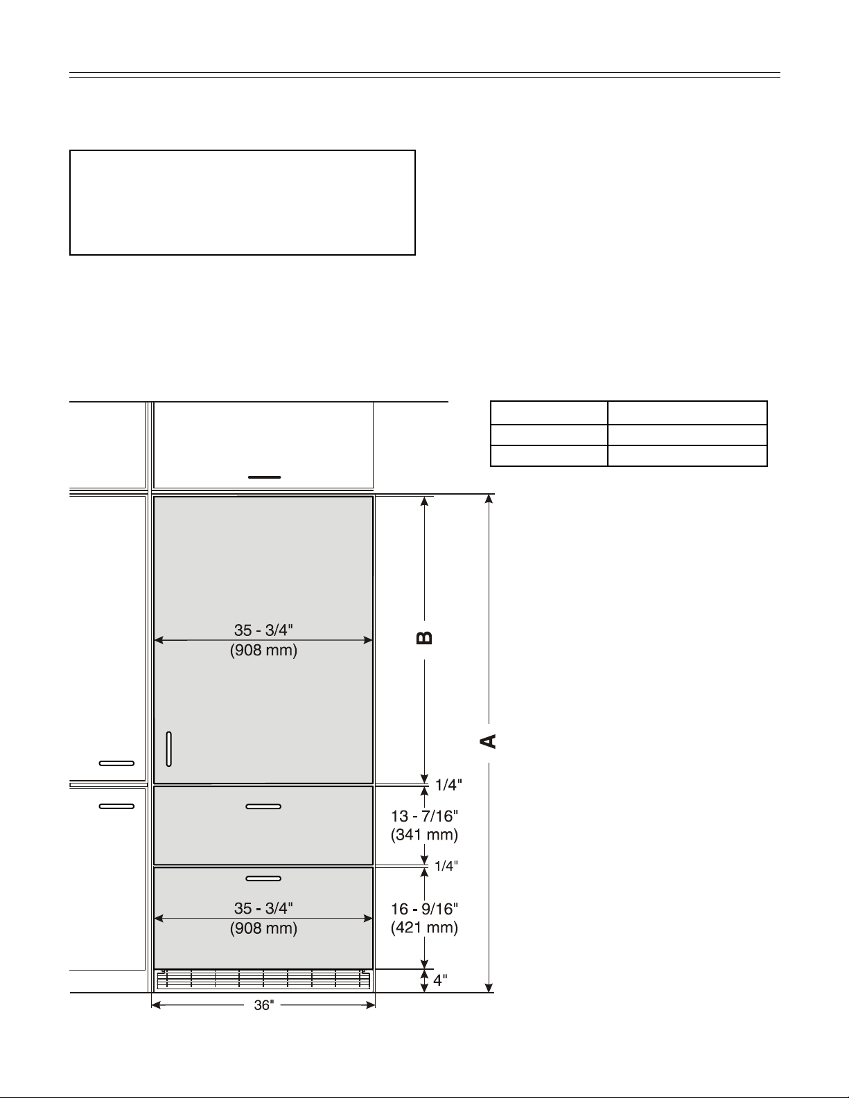
Cabinet Opening Dimensions - Figure 4
I
nformatIon
Inset cabinet
Depth D
24" + panel thickness 24"
Frameless/faceframe cabinet
Depth D
IMPORTANT
For 24" cabinets, the water line
opening must be in the location
as shown.
With cabinets deeper than
24", there is room to fit the
pipe behind the appliance
and the wall so there are no
requirements for the water line
lead out position.
The free length of the water
supply line must be at least
31-1/2" (800 mm) when the tube
comes out of the prescribed
opening.
Do not install the shut-off valve
behind the appliance.
For appliance with panel to be flush,
adjacent cabinetry depth must equal
appliance depth (24") plus panel
thickness (5/8" - 3/4").
This is where the power cord
extends from the back of the
appliance.
Free length of the power cord
= 90 inch (2280 mm)
Be sure to take these specifications into consideration
when choosing the location of
the electrical outlet.
IMPORTANT
The electrical outlet must
not be situated behind
the appliance and must
be easily accessible.
Water supply line
36" Single
72" Side by Side
Figure 4
5
Page 6
p
lannIng
I
nformatIon
Panel Dimensions - Inset Installation Style - Figure 5
The panels should be at least 5/8 inch (16 mm) thick to
Appliance and panels sit fully within the opening and
are flush with what could be its own box, between
two pantry cabinets or decorative columns, etc. This
is the most common installation scenario.
You can order stainless steel panels for inset installation style.
Refrigerator door panel 80"- article number 9900 333-00
Refrigerator door panel 84"- article number 9900 331-00
Freezer drawer panels - article number 9900 323-00
allow the connecting rails to be fastened to them.
IMPORTANT
The maximum panel thickness is 3/4" (19 mm).
The door panel weight must not exceed 60 lb (27 kg).
Cabinet opening A Refrigerator door panel B
80" (2032 mm) 45-1/4" (1150 mm)
84" (2134 mm) 49-1/4" (1251 mm)
Figure 5
6
Page 7

p
lannIng
I
nformatIon
Panel Dimensions - Frameless Installation Style - Figure 6
The gap between panels with frameless installation style
With this installation style, these wider appliance
panels partially overlay the shared side gables of
adjacent cabinetry so as to mimic the look of a frameless style cabinet.
is 1/4" (6 mm). The panels should be at least 5/8 inch
(16 mm) thick to allow the connecting rails to be fas-
tened to them.
IMPORTANT
The maximum panel thickness is 3/4" (19 mm).
The door panel weight must not exceed 60 lb (27 kg).
Cabinet opening C Refrigerator door panel D
80" (2032 mm) 45-3/4" (1162 mm)
84" (2134 mm) 49-3/4" (1264 mm)
Figure 6
7
Page 8

B
lockIng for
S
afety
Mounting the Anti Tipping Device
on Concrete Floors - Figure 7 - 8
Secure the appliance in place so it does not tip forward
when the fully stocked door is opened.
bracket is provided with the appliance.
1. Mark the center line of the appliance on the back wall.
Align the anti tipping bracket center to this line.
Be sure that there is no plumbing or
electrical wiring located in this area which
screws or drills could damage.
The anti tipping
Wall
Figure 7
2. Drill a 3/8" diameter hole in any position as shown in
Figure 5 using a carbide drill bit.
The depth of the holes must exceed the overall length
of the anchors provided.
Clean the holes after drilling.
3. Attach washer and screw on hex nut to the end of
each anchor.
Drive in all 3 anchors.
Align the bracket center to the center line on the back
wall again.
Fasten the anchors by turning the hex nut.
4. Fasten bracket with 3 screws (1/4" x 2-1/8") into the
wall plate (Figure 8).
Mounting the Anti Tipping
Device on Wooden Floors - Figure 9
1. Mark the center line of the appliance on the back wall.
Align the anti tipping bracket center to this line.
Wall plate
Wall
Figure 8
Wall plate
Be sure that there is no plumbing or
electrical wiring located in this area which
screws or drills could damage.
2. Fasten bracket to the wooden floor using 5 screws
(1/4" x 2-1/8"). Drill pilot holes if necessary.
3. Fasten bracket with 3 screws (1/4" x 2-1/8") into the
wall plate.
Wall
Figure 9
Wall plate
8
Page 9

B
lockIng for
S
afety
Mounting the Anti Tipping
Device in Cabinets deeper than
24" - Figure 10 - 11
To ensure the compressor mounting plate reaches the
anti tipping bracket in cabinets deeper than 24", a wooden spacer must be mounted between the appliance back
and the wall. The anti tipping bracket will be fastened to
the floor downwards and to the spacer backwards.
Be sure the wooden spacer is fastened
securely to the floor.
Measuring for mounting the wooden spacer on
inset kitchen cabinets - Figure 10
Depth of spacer depending on clearance between appliance and wall
Cover Strips - Figure 12
Apply cover strips above, between and below the securing plates on the side walls of the appliance.
Cut the cover strips to the length shown in Figure 12.
Fit the adhesive cover strips leaving a gap of 1/4" to each
securing plate. This
ensures problem-free
fitting of the covers.
Panel thickness
Figure 10
Measuring for mounting the wooden spacer on
frameless kitchen cabinets - Figure 11
Depth of spacer depending on clearance between appliance and wall
Figure 11
IMPORTANT
If the floor slopes down sideways, the anti-tipping
bracket must be fitted horizontally. Lay down spacers
in the appropriate positions.
Figure 12
9
Page 10

I
ce
m
aker
Safety Instructions and Warnings
• Donotinstallthewaterconnectionwhilethecombined refrigerator-freezer is connected to an electrical outlet.
• Theconnectiontothewatersupplymayonlybe
made by a trained and licensed plumber.
• Allequipmentanddevicesusedtosupplythewater
to the appliance must comply with the current regulations for your geographical area.
WARNING!
Connect to potable water supply only.
Water Connection Requirements
• Thewatersupplypressurerequirementsaredifferent
based on whether or not the supplied Liebherr water
filter is installed.
With the filter installed, the pressure must be in the
range of 40-90 psi (2.8-6.2 bar).
Water Connection Adapter -
Figure 13
IMPORTANT
Only use the supplied adapter for connection to
the solenoid valve. The solenoid valve has a metric
R3/4 male connector. Any attempt to use other
adapters for connection could damage the thread on
the solenoid valve.
The supplied adapter enables different connection
options for different kinds of water lines. A water line is
not supplied with the appliance.
Seal
Connects to 1/4" compression end
Angle connector
Connects to 1/4" compression end
Valve connector (union nut
for connection to the solenoid valve)
Without the filter installed, the acceptable pressure
range is 22-87 psi (1.5-6 bar).
Failure to meet these requirements will likely result
in ice maker malfunction and possibly cause a water
leakage that can damage flooring and surrounding
furniture.
• Ashut-offvalve,mustbeinstalledbetweenthehose
line and the main water supply so the water supply
can be stopped if necessary.
IMPORTANT
Do not install the shut-off valve behind the appliance.
Union nut with compression ring
for use with 1/4" OD copper lines
Figure 13
The connection to the valve connector can be done with
or without the angle connector, as required.
Braided style ice maker hoses can be connected directly to the threaded ends.
For connection with 1/4" OD copper lines, use the union
nut with compression ring.
IMPORTANT
Make sure that the connection is fitted with a seal
and is tight.
• Insertthewaterstrainersuppliedintothe
valve connector (Figure 14).
10
Figure 14
Page 11

Connection to the Water Supply
1. Move the appliance
towards the final position and leave enough
space to work behind.
2. Insert the water supply line into its intended opening at the
back of the appliance
(Figure 15).
3. Move the power supply
line to the area of the
electrical outlet.
WARNING!
Donotconnecttotheelectricaloutlet
before the installation is completed and
the water line is connected to the solenoid
valve.
Figure 15
I
ce
m
aker
WARNING!
To prevent the appliance from tipping
forward the compressor mounting plate
must have contact with the anti tipping
bracket (Figure 16).
5. Remove the cover from the solenoid valve
(Figure 17).
6. Connect the water line to the adapter in the respective configuration, depending on the type of water
line used. Figure 18 shows the configuration with a
copper line as an example.
7. Bleed the air from the water line by opening the
water supply temporarily.
4. Push the appliance slowly to the back wall until the
compressor mounting plate makes contact with the
anti-tipping bracket (Figure 16).
Wall
Appliance
Anti tipping bracket
Compressor mounting
plate
Figure 17
8. Screw the adapter
onto the solenoid
valve (Figure 18).
Figure 16
9. Open the shut-off valve
for the water supply and
check the entire water system
for leaks.
Figure 18
11
Page 12

I
nStallatIon
Leveling the Appliance - Figure 19
1. Adjust the height of the
appliance at the front
by twisting the leveling
feet 1 (A/F 27).
Use the open-ended
spanner provided.
2. Adjust the height of the
appliance at the rear
by turning the adjusting
2
bolts
3. Rotate leveling feet
1
against the floor.
To prevent the appliance from tipping
forward the leveling feet 1 (Figure 19)
must have contact with the floor.
.
until firmly in place
Figure 19
Adjusting the refrigerator door
Figure 21
The lateral tilt of the refrigerator door can be adjusted
if required. Undo screws 1. Adjust the lateral tilt using
the grub screw 2 (Allen key A/F 2.5).
-
Fastening the Appliance in the
Recess - Figure 20
Fasten the appliance in the recess through the premounted supports at left and right on the appliance
housing using screws 4 x 16 mm. Then click the covers
supplied into place.
Figure 21
Figure 20
12
Page 13

I
nStallatIon
Adjusting the front of the drawer
- Figure 22
If required, the front of the freezer drawers can be
adjusted.
Transfer the screws shown in the illustration (on the left
and right sides of the freezer drawer) individually to the
long slots below.
Tighten the screws in the front of the drawer once it is in
the right position.
Side view of the freezer drawer
pulled out
Before Mounting the Door Panels
- Figure 23
Remove cover 1 and unscrew the upper and lower
attachment bracket 2 of the refrigerator door. These
brackets will be mounted onto the refrigerator door
panel.
IMPORTANT
The nuts are needed to fit the premounted
panel onto the refrigerator door.
Figure 22
Figure 23
Unscrew the attachment brackets of both freezer drawers. These brackets will be mounted onto the freezer
drawer panels (
The screws are needed to fit the
premounted panels onto the freezer
drawers.
Figure 24).
IMPORTANT
13
Figure 24
Page 14

I
nStallatIon
Mounting the Attachment Brackets onto the Door Panels - Figure 25
Mark a line with a distance of 41" and 4-1/4" from the bottom of the refrigerator door panel
Align one of the dismounted brackets of the refrigerator door to the line on the refrigerator door panel as shown in
Figure 25 a.
Align the second bracket of the refrigerator door to the bottom line on the refrigerator door panel as shown in
Figure 25 b.
Fasten the brackets provided onto the freezer drawer panels using three screws (4 x 16 mm) for each bracket considering the measurement in
Fasten the bracket with any hole wherever possible using a minimum of 6 screws 4 x 16 mm.
Fasten the bracket with any hole wherever possible using a minimum of 6 screws 4 x 16 mm.
Figure 25 c
Refrigerator door panel
.
.
Figure 25 a
Freezer drawer panel
Freezer drawer panel
Figure 25
Figure 25 b
Figure 25 c
14
Page 15

Mounting the Refrigerator Door Panel
I
nStallatIon
1. Turn in the adjusting bolts on the bottom of the refrigerator door as far as possible (Figure 26).
Figure 26
4. Close the door and check the height of the panel.
5. Align the panel in its vertical position if necessary.
Loosen the hex nuts and turn the adusting bolts
(Figure 28).
Figure 28
2. Open the refrigerator door and hang the panel on the
top adjusting bolts (Figure 27).
3. Screw on the hex nuts to the adjusting bolts and finger tighten temporarily (Figure 27).
Figure 27
6. Align the panel horizontally (with the long holes in the
attachment bracket) (Figure 29).
7. Tighten the hex nuts.
15
Figure 29
Page 16

I
nStallatIon
8. Turn the adjusting bolts (bottom refrigerator door)
until they make contact with the attachment bracket
(Figure 30).
10. Loosen the three screws on the top of the attachment bracket, align the panel as shown in Figure 32
and tighten the screws. This can also be done with
the lower attachment bracket.
Figure 30
9. Screw on the hex nuts and tighten (Figure 31).
Figure 31
Figure 32
11. Click cover 1 into place.
Insert the cover strip provided
tor door and panel (Figure 33).
2 between refrigera-
16
Figure 33
Page 17

I
nStallatIon
Mounting the Freezer Drawer
Panels - Figure 34
1. Pull out the upper freezer drawer and screw on the
panel with three screws at left and right hand side
using the screws as shown in Figure 34.
2. Close the drawer and check the position to the surrounding cabinet panels. Align the panel in vertical direction by loosening the screws left and right.
Finally tighten the screws.
Donotovertighten.Donotuseapower
driver.
3. Pull out the lower freezer drawer and fasten the lower
panel in the same way.
4. Finally cover the gap between the drawer and the
panel of both freezer drawers with the strips provided.
Remove the foil from the adhesive surface of the strip
and stick on the top of the appliance drawer making
sure the flexible gasket is fully inserted in the gap.
Mounting the Ventilation Grille -
Figure 35, 36
1. Pull out the bottom freezer drawer.
2. Remove the blue protection film from the dust filter
provided and insert the filter into its opening in the toe
kick area as shown in
at the bottom, press down the button and click into
place.
Figure 35. Engage the filter
Figure 35
3.5 x 13 mm screw
Figure 34
3. Mount the ventilation grille as shown in Figure 36.
IMPORTANT
Only use the ventilation grille provided with the
appliance. This grille is required for proper operation of
the appliance.
The ventilation opening must not be covered with a
cabinet base.
Failure to use the supplied grille can result in product
failure and will void the warranty.
17
Figure 36
Page 18

For Service in the U.S.
LiebherrServiceCenter
Toll Free: 1-866-LIEBHERor1-866-543-2437
Email: Service-appliances.us@liebherr.com
PlusOneSolutions,Inc.
3501 Quadrangle Blvd, Suite 120
Orlando, FL 32817
For Service in Canada
LiebherrServiceCenter
Toll Free: 1-888-LIEBHERor1-888-543-2437
www.euro-parts.ca
EURO-PARTSCANADA
39822 Belgrave Road
Belgrave, Ontario, N0G 1E0
Phone: (519) 357-3320
Fax: (519) 357-1326
 Loading...