

Liebherr HC1070 Installation
Installation
Instructions
Combined fridge-freezer for
integrated use, door-on-door
Instrucciones
de montaje
Combinado frigorífico-congelador,
integrable, puerta fija
Instructions
de montage
Combiné réfrigérateur-
congélateur, intégrable, porte fixe
HC 1070 / HC 1030
080414 7085586 - 00
General safety information
Contents
1 General safety information........................... 2
2 Transporting the appliance.......................... 2
3 Setting up the device.................................... 2
4 Appliance dimensions................................... 4
5 Recess dimensions....................................... 4
6 Cabinet door................................................... 5
7 Air circulation in the kitchen cabinet........... 7
8 Reversing the door........................................ 8
9 Installing the appliance in the recess.......... 12
10 Disposal of packaging................................... 21
11 Connecting the appliance............................. 21
The manufacturer is constantly working to improve all
models. Therefore please understand that we reserve the
right to make design, equipment and technical modifications.
To get to know all the benefits of your new appliance,
please read the information contained in these instructions carefully.
The instructions apply to several models, so there may be
differences. Sections which only apply to certain appliances are indicated with an asterisk (*).
Instructions for action are marked with a , the
results of action are marked with a .
mains quickly in an emergency. It must not be
behind the back of the appliance.
DANGER indicates a hazardous situation,
which if not avoided, will result in
death or serious injury.
WARNING indicates a hazardous situation,
which if not avoided, could result in
death or serious injury.
CAUTION indicates a hazardous situation,
which if not avoided, will result in
minor or moderate injury.
NOTICE indicates a hazardous situation,
which if not avoided, could result in
damage to property.
Note indicates useful advice and tips.
2 Transporting the appliance
CAUTION
Risk of injury or damage if incorrectly transported.
Transport the appliance in its packaging.
u
Transport the appliance upright.
u
Do not move the appliance on your own.
u
3 Setting up the device
1 General safety information
-
Read and follow these instructions. They
contain safety advice which is important for
safe and problem-free installation and operation. Always read and follow the safety advice.
-
It is important that the guidelines and instructions in this manual are followed so that the
appliance is correctly installed and operates
properly Read and understand all information
in this manual before the appliance is installed
-
Risk of asphyxiation and crushing:
Remove doors and shelves from old appliances to prevent them from becoming a potential hazard to children at play.
-
Only install, connect and dispose of the appliance in accordance with the instructions. Pay
particular attention to “niche dimensions”
(see 5) and “ventilation and fume extraction in
kitchen units” (see 7) .
-
The socket must be easily accessible so that
the appliance can be disconnected from the
WARNING
Risk of fire due to short circuit.
If the power cable or plug of the appliance or another
appliance and the back of the appliance touch each other
the power cable or plug will be damaged by the vibrations
of the appliance which could lead to a short circuit.
Install the appliance so that it does not touch any plugs
u
or power cables.
Do not connect the appliance or other appliances to the
u
sockets on the back of the appliance.
WARNING
Risk of fire due to moisture!
If live parts or the power cord get wet, this can cause a
short circuit.
The appliance is designed for use in enclosed spaces.
u
Do not operate the appliance in open space or in damp
areas or where there is spray.
Only operate the appliance after it has been installed.
u
2 * Depending on model and options
WARNING
Risk of fire due to refrigerant.
The refrigerant contained within the appliance, R 600a, is
environmentally friendly, but flammable. Leaking refrigerant can ignite.
Do not damage the pipes of the refrigerant circuit.
u
WARNING
Danger of fire and damage!
Do not place devices that give off heat, e.g. micro-
u
waves, toasters, etc. on the appliance.
NOTICE
Risk of damage caused by condensation
Installing the appliance next to any other refrigerator or
freezer can cause condensation or damage to the Liebherr appliance.
Do not install this appliance next to any other refriger-
u
ator or freezer except another Liebherr model. Liebherr
models are designed to allow side-by-side installation.
They are equipped with a heating system to eliminate
condensation when refrigerators or freezers are
installed side-by-side.
NOTICE
Risk of damage for the finished floor surface!
Protect the finished floor surface before you uncrate the
u
unit.
Setting up the device
In accordance with EN 378 for each 0.28 oz (8 g) of R
q
600a refrigerant the room where the appliance is
installed must have a volume of 35.5 ft3 (1 m3). If the
installation room is too small an inflammable gas/air
mixture may arise if the refrigerant circuit leaks. You will
find details of the required quantity of refrigerant on the
rating plate inside the appliance.
If the appliance is installed in a very damp environment
q
condensate water may form on the outside of the appliance. Always ensure good ventilation.
The load-bearing capacity of the floor must be sufficient
q
for the weight of the appliance plus about 1200 pounds
(544 kg) of food weight.
The electrical socket must assessed precisely to
q
ensure the correct position and fuse.
Do not restrict ventilation. Sufficient ventilation is
q
required for the appliance to operate correctly. The
ventilation grid fitted at the factory guarantees an effective ventilation gap on the appliance of 31 in.
(200 cm2). If you replace the ventilation grid with a
fascia, this must have at least the same size or larger
ventilation gap as the manufacturer's ventilation grid.
Note down the type (model, number), appliance name,
u
appliance or serial number, date of purchase and
manufacturer's address in the place provided for this in
the Use & Care Manual.
Remove all materials that could prevent it from being
u
installed properly or prevent proper ventilation from the
back or the side panels of the appliance.
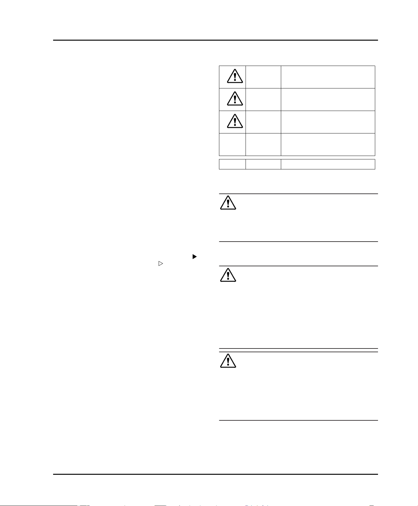
Remove the red transport
u
safety device. Close off any
holes that have been
revealed with plugs (60).
2
WARNING
Danger of damage from overheating. May restrict operation.
Keep ventilation openings, in the appliance enclosure
u
or in the built-in structure, clear of obstruction.
WARNING
Danger of tilting.
To avoid a hazard due to instability of the appliance, it
u
must be fixed in accordance with the instructions.
If possible, have a professional install the appliance in
q
your kitchen cabinet unit.
If the appliance is damaged check with the supplier
q
immediately before connecting it.
The floor of the installation site must be horizontal and
q
level.
Do not install the appliance in direct sunlight or next to
q
an oven, heater or similar heat source.
Do not install the appliance on your own. It is better to
q
do this with two or more people.
After installation:
Remove protective films, adhesive tapes and transport
u
safety devices, etc.
Note
Clean the appliance (see operating instructions,
u
"Cleaning the appliance" section).
* Depending on model and options 3
Appliance dimensions
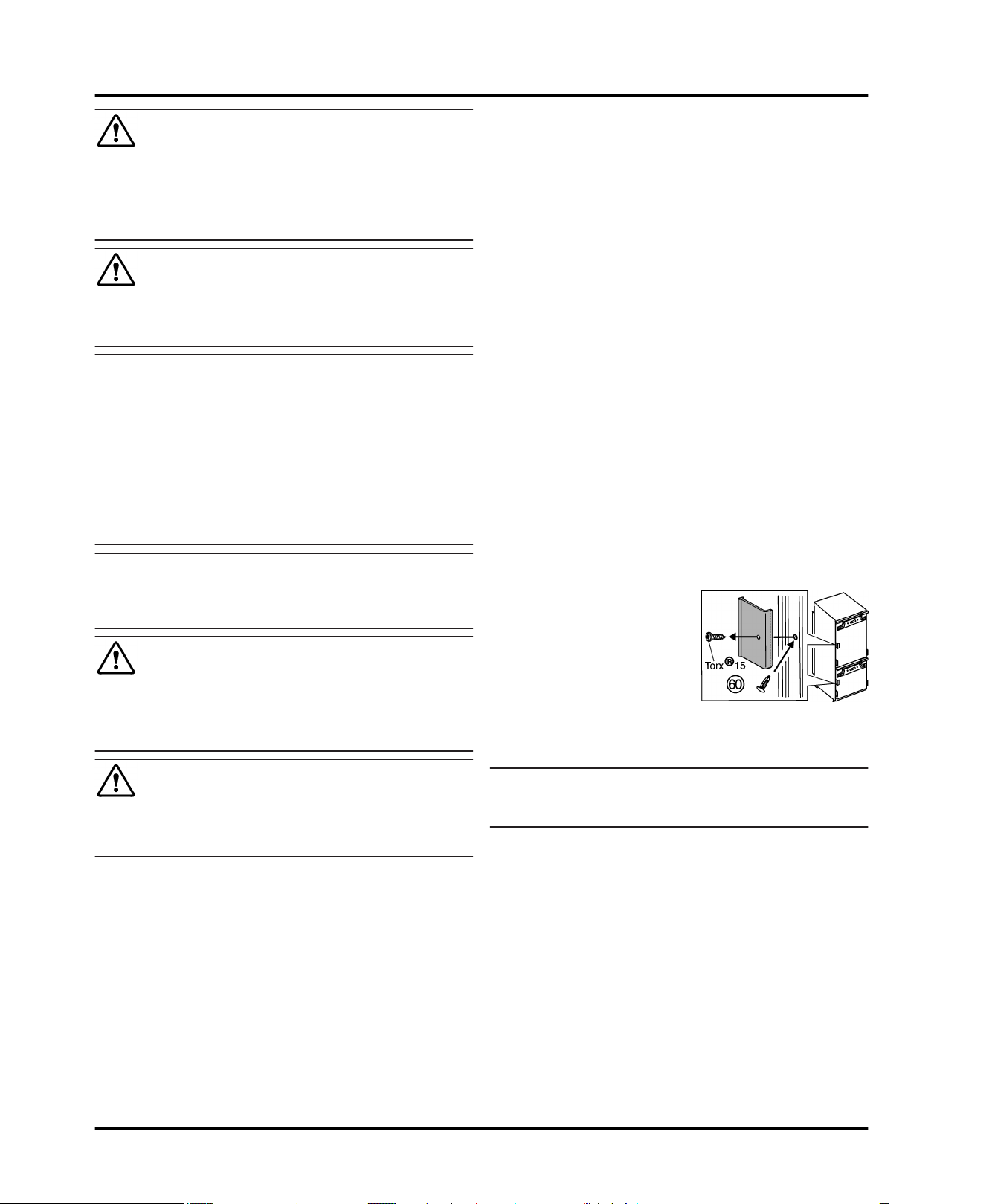
4 Appliance dimensions
Fig. 1
in. mm
A
B
C
D
E
22 in. 559 mm
21 7/16 in. 544 mm
69 11/16 in. 1770 mm
27 3/8 in. 695 mm
5/8 in. 15 mm
5 Recess dimensions
This is a built-in appliance and is therefore completely
enclosed by a kitchen cabinet The kitchen cabinet
surrounding the appliance must be designed exactly in
accordance with the specified fitting dimensions and must
allow sufficient air circulation to ensure correct operation
of the appliance.
Fig. 2
in. mm
F
G
H
J
K
L
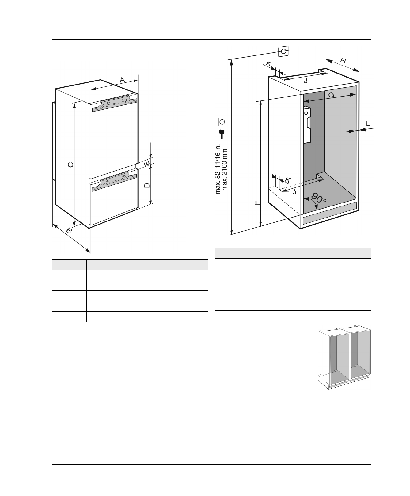
For side-by-side installation of two
u
appliances next to each other
install each appliance in its own
kitchen cabinet.
Check the wall thickness of adjacent cabinets: It must
u
be at least 5/8 in. (16 mm).
Only install the appliance in solid, fixed kitchen cabi-
u
nets. Ensure that the cabinets cannot tip over.
Align the cabinets with a spirit level and a try square. If
u
necessary level them by putting something underneath
them.
Ensure that the floor and the side panels of the cabinet
u
are at right angles to each other.
69 3/4 — 70 3/8 1772 — 1788
22 — 22 3/4 560 — 578
min. 21 5/8 Min. 550
min. 19 11/16 Min. 500
min. 1 5/8 Min. 40
max. 3/4 max. 19
4 * Depending on model and options
6 Cabinet door
Two doors are required for the kitchen cabinet: a top
one for the fridge section and a bottom one for the
freezer section.
The doors must be at least 5/8 in. (16 mm) and no more
than 3/4 in. (19 mm) thick.
When the two doors are closed the gap between the
top and bottom door must be at least 1/8 in. (3 mm).
The gap between the cabinet doors must be the same
as the gap between the appliance doors.
There must be a gap of at least 1/8 in. (3 mm) between
the door and the cupboard door above it (if there is
one).
The width of the cabinet doors depends upon the style
of the kitchen and the size of the gap between the door
panels of the cupboard. Normally a vertical gap of
1/8 in. (3 mm) should be left between the cabinet
doors.
The upper edges of the top door and the bottom door
should be the same as the on the cupboard(s) next to it
if there are any other cupboards.
Cabinet door
The unit doors must be assembled flat and free from
tension.
NOTICE
An excessively heavy unit door can cause potential
damage!
If the unit door is too heavy, we cannot rule out damage to
the hinges, which may compromise the use of the unit.
Before installing the unit door, ensure the door does not
u
exceed the permissible weight.
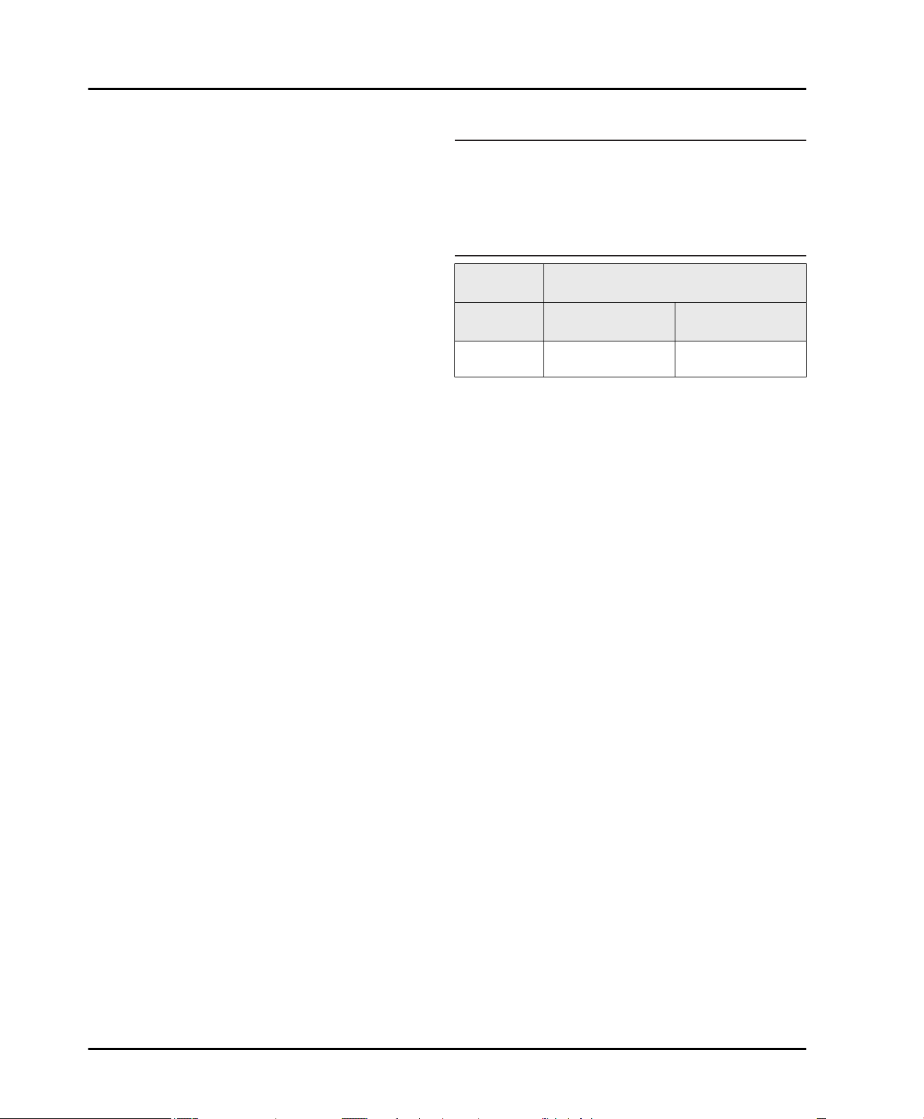
Appliance
type
HC 1070, HC
1030
Maximum weight of unit door
Fridge compartment door
30.5 lbs (14 kg) 26.5 lbs (12 kg)
Freezer compartment door
* Depending on model and options 5
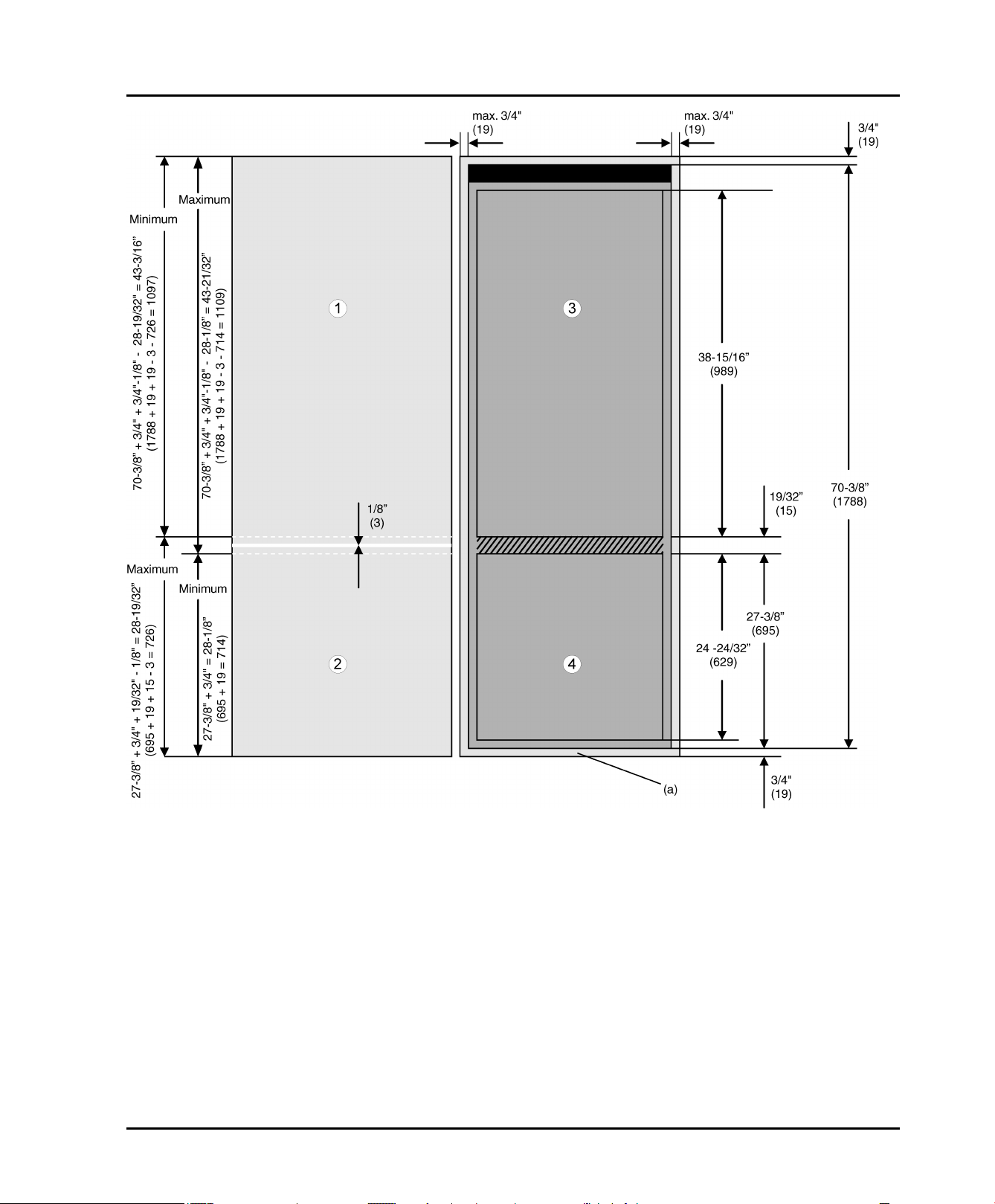
Cabinet door
Fig. 3
The height of the freezer door is 24-24/32 in. (629 mm).
In order to cover the bottom section of the appliance:
u
extend the plate height to 27-3/8 in. (695 mm).
The thickness of the floor plate is normally 3/4 in.
(19 mm).
In order to cover the front of the floor plate
u
extend the plate height to 27-3/8 in. + 3/4 in. =
28-1/8 in. ( 695 mm + 19 mm = 714 mm ).
If no cabinet doors have yet been fitted the gap between
the freezer section door
door
Fig. 3 (3)
have been fitted the gap between the two doors
is about 1/8 in. (3 mm) and must be inside the hatched
area.
6 * Depending on model and options
is19/32 in. (15 mm) After the cabinet doors
Fig. 3 (4)
and the fridge section
Fig. 3 (a)
Fig. 3 (1,2)
Of course, the final door height depends on the size of the
gap on the doors of the kitchen cabinets that are to the
right and left of the fitted appliance cabinet.
If there are other cabinets next to the fitted appliance
cabinet they normally have a gap between two drawers or
:
doors. Depending on the design of your kitchen these
gaps are about 1/8 in. (3 mm) wide.
In this case increase the plate height to 27-3/8 in. +
u
3/4 in. + 19/32 in. - 1/8 in. = 28-19/32 in. ( 695 mm +
19 mm + 15 mm - 3 mm = 726 mm ).
The height of the refrigerator door leaf is calculated as
follows:
Total height of the cupboard (i.e. 70-3/8 in. (1788 mm))
u
plus thickness of the cover and floor plate (normally
3/4 in. (19 mm)) minus the height of the freezer cabinet
door leaf (xxx in. (xxx mm)) as calculated above and
minus the gap width (approximately 1/8 in. (3 mm)):
70-3/8 in. + 3/4 in. + 3/4 in. - xxx in. - 1/8 in. = 71-3/4 in.
- xxx in. ( 1788 mm + 19 mm + 19 mm - xxx mm - 3 mm
= 1823 mm - xxx mm )
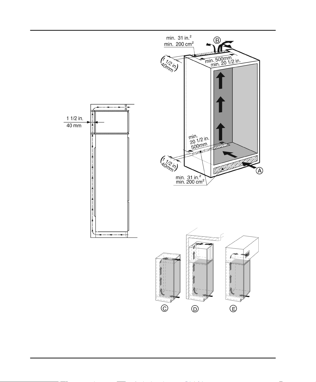
7 Air circulation in the kitchen cabinet
Air circulation in the kitchen cabinet
Fig. 4
There must be an effective ventilation gap of at least
31 in2 (200 cm2) per appliance for the air inlet
and the air outlet
Basically, the bigger the ventilation gap, the more
energy-saving the operation of the appliance.
The depth of the ventilation shaft on the back wall of
the cabinet must be at least 1-1/2 in. (40 mm).
The top ventilation gap can be set up either directly
above the appliance with an optional ventilation grid
Fig. 6 (C)
as an air vent in a false ceiling
near the ceiling, above the cabinet
Fig. 5 (B)
.
Fig. 6 (E)
.
Fig. 5 (A)
Fig. 6
Fig. 6 (D)
Fig. 5
or
* Depending on model and options 7
Reversing the door
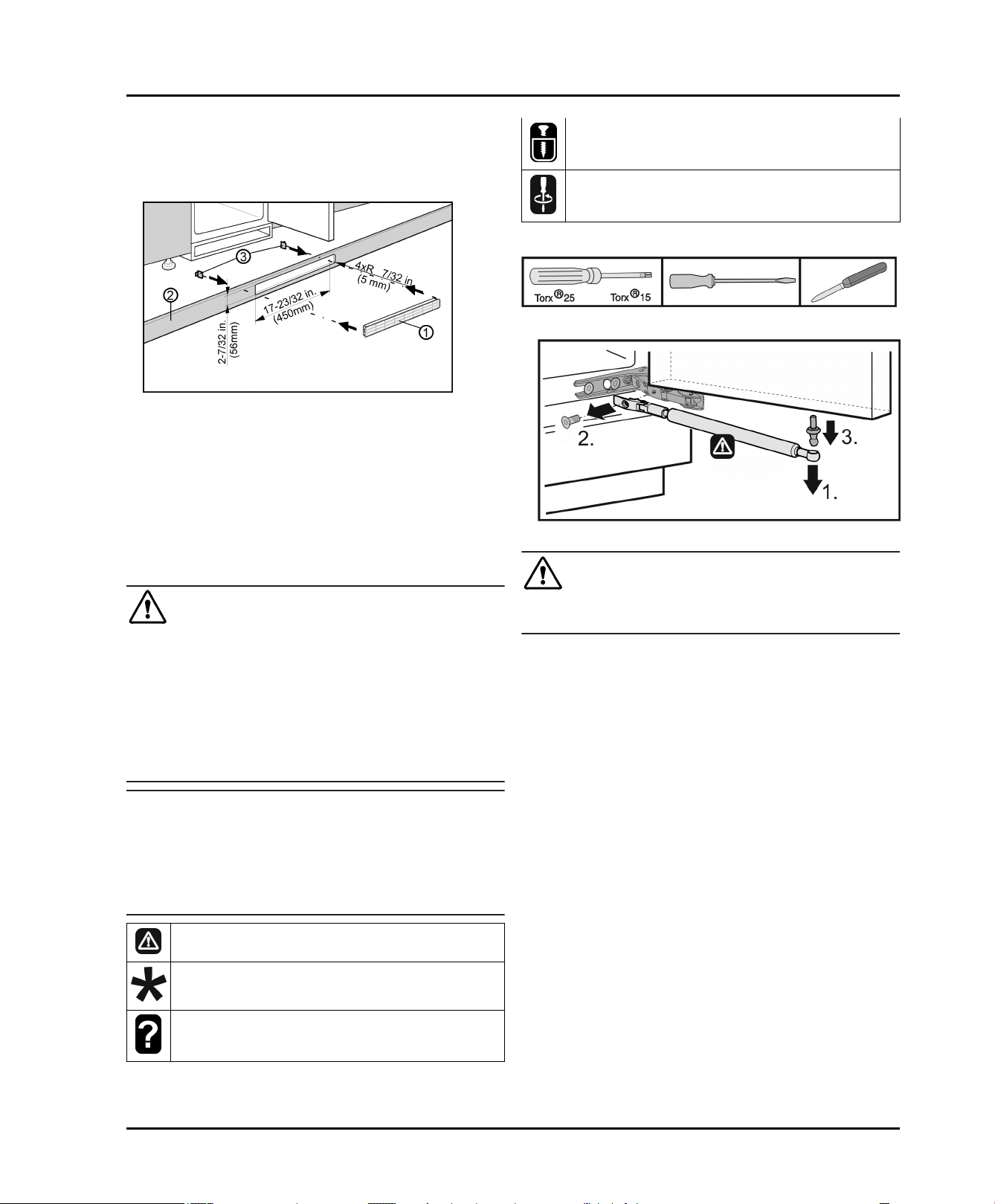
Ventilation from underneath through the floor of the
kitchen cabinet can be set up with the supplied ventilation
grid
Fig. 7 (3)
or an air vent with at least a 31 in2 (200 cm2)
cross section area. If you use the supplied ventilation grid
Fig. 7 (1)
u
please proceed as follows:
Fig. 7
Cut a hole 17-23/32 in. (450 mm) wide and 2-7/32 in.
(56 mm) high in the floor of the kitchen cabinet.
Insert the ventilation grid
u
cabinet floor
Slide the snap connectors
u
Fig. 7 (2)
.
Fig. 7 (1)
Fig. 7 (3)
into the cut out in the
into the grid from
behind until the hooks touch the cabinet floor.
Fit the cabinet floor (with the ventilation grid snapped
u
into place) into the cabinet.
Only undo the screw. Don't take it out.
Check the screws and if necessary tighten them.
Required tool:
Fig. 8
Fig. 9
8 Reversing the door*
WARNING
Risk of bodily injury due to the door falling off.
If the fasteners are not installed with the proper torque,
the door may fall off. In addition, the door may not close,
thus impairing the cooling performance of the appliance.
Tightly secure the hinges along ball stud of the soft
u
stop mechanism by applying a torque of 3 lb-ft (4 Nm).
Tighten the soft stop mechanism retainer firmly with
u
2.5 lb-ft (3 Nm).
Check all screws and retighten if necessary.
u
Note
The door stop can only be changed if there is sufficient
space above to remove the hinge fixing bracket and fit it
on the opposite side again. This is not normally the case
when installing in a recess.
Change the door stop before the appliance is installed
u
in the recess.
There is the risk of injury when doing this. Obey the
safety instructions.
The instructions apply to several models. Only perform
this step if it applies to your appliance.
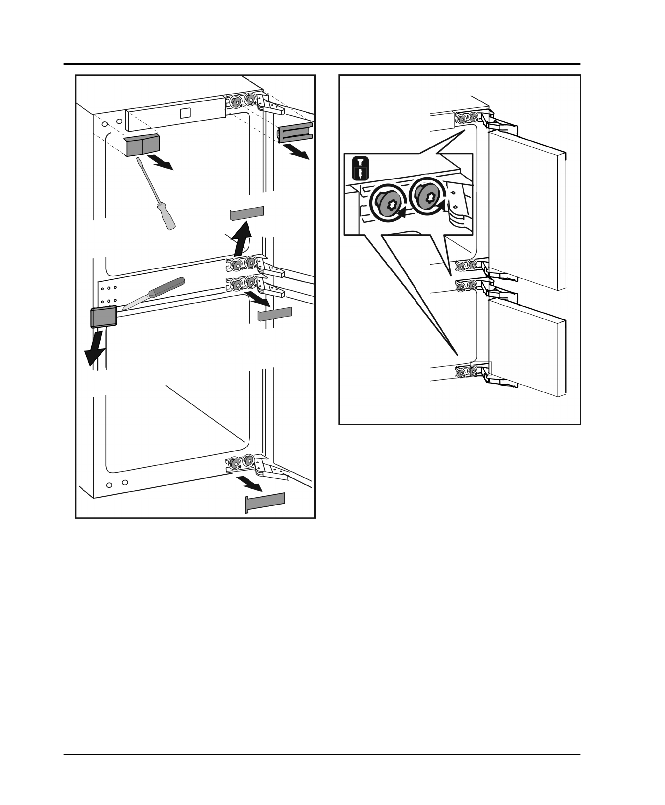
CAUTION
Risk of injury if soft stop contracts!
Carefully remove soft stop damper.
u
Removing the soft stop damper: Remove the soft stop
u
damper from the ball stud (1). Unscrew the retainer (2).
Remove the ball stud with a screwdriver (3).
Select one of the alternatives shown.
8 * Depending on model and options
Reversing the door
Fig. 10
Remove covers.
u
Fig. 11
Undo the screws on the hinges but do not remove
u
them.
* Depending on model and options 9
Reversing the door
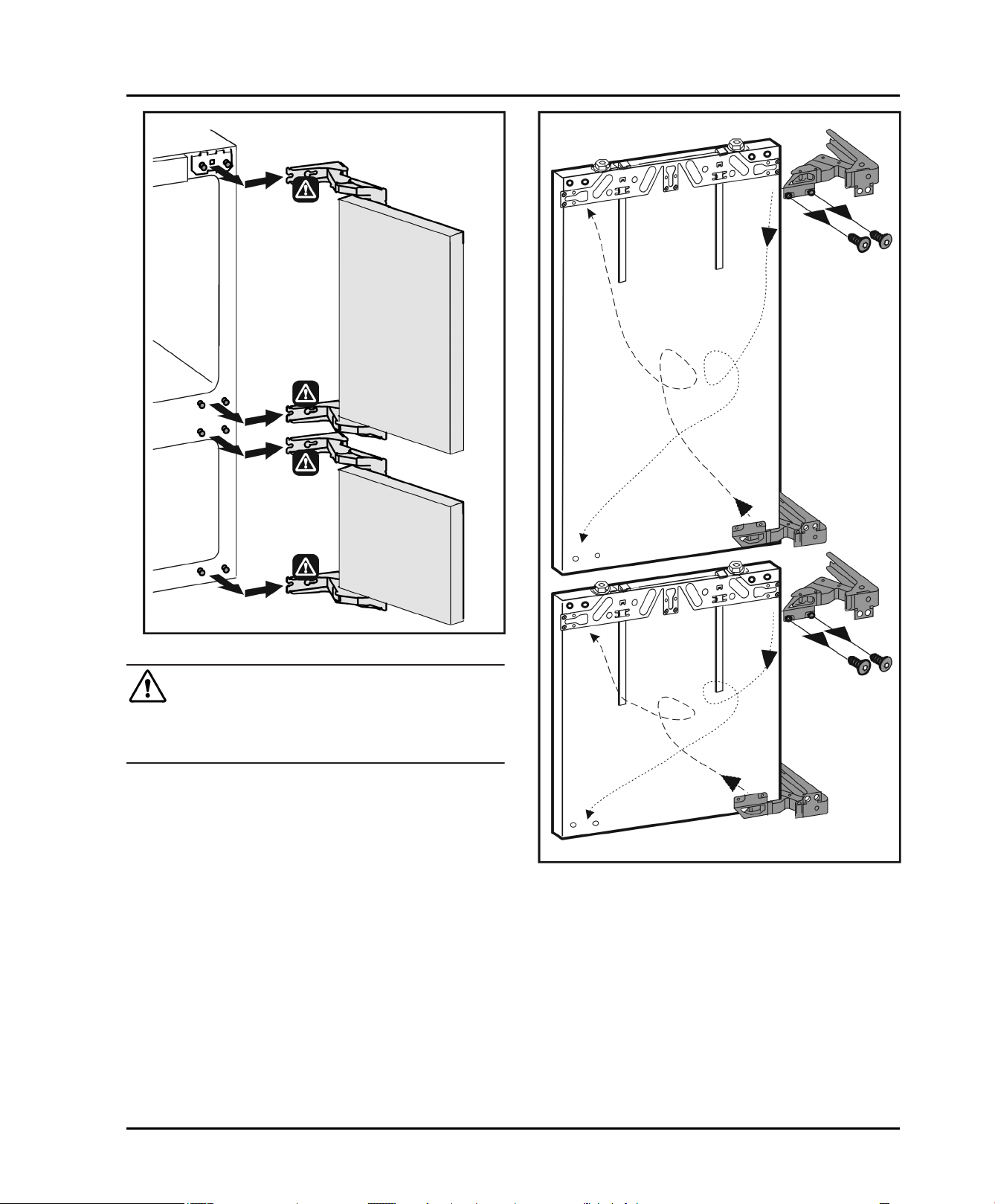
Fig. 12
CAUTION
Hinges are spring-loaded and can cause pinching injuries!
Leave hinges open.
u
Removing the door: Push the door forward and then
u
out, unhook it and put it to one side.
Fig. 13
Swap the hinges.
u
10 * Depending on model and options
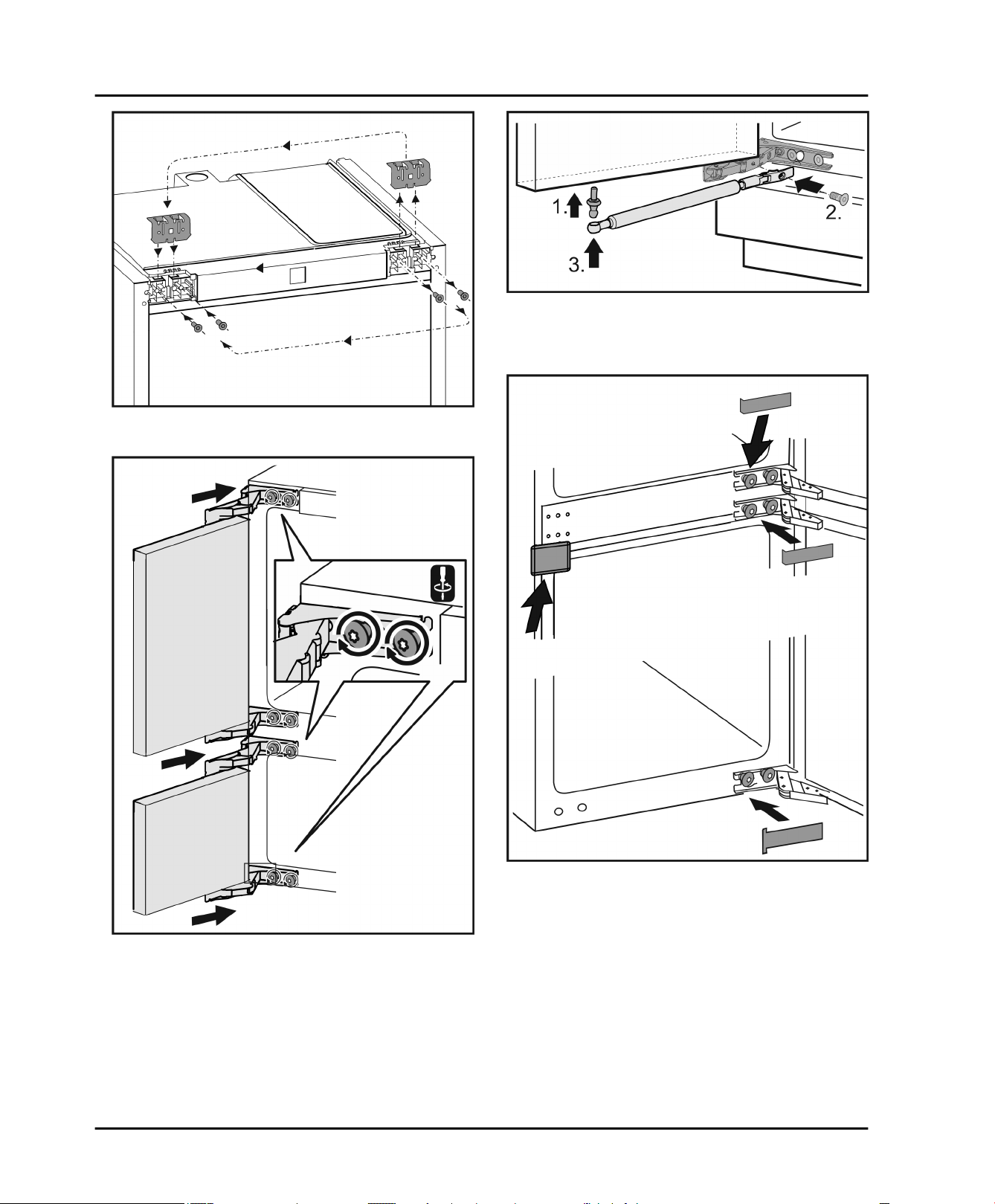
Fig. 14
Swap the fixing bracket to the opposite side.
u
Reversing the door
Fig. 16
Re-attaching the soft stop mechanism: Screw in the
u
ball studs (1), tighten the retainer (2) and attach the soft
stop dampers into the ball studs.
Fig. 17
Check all screws and retighten if necessary.
u
Fit all covers except for the top left and the top right.
u
Only fit the top covers after installing the appliance into
Fig. 15
Fitting the door again: Reattach the door to the hinges
u
and tighten the screws.
* Depending on model and options 11
the cabinet again.
Installing the appliance in the recess.
9 Installing the appliance in the recess.
WARNING
Risk of fire due to short circuit.
When inserting the appliance into the recess do not
u
squash, jam or damage the power cable.
Do not operate the appliance with a faulty power cable.
u
NOTICE
Risk of damage to the hinges.
The hinges could be damaged if the appliance gets
caught on the door when it is being moved.
Always hold onto the body when relocating and moving
u
the appliance.
The following accessories are available from Customer
Services for installing the appliance into a recess:
Set to restrict the door opening angle
to 90°
Set to fit divided cabinet fronts
Set with covers for concealed hinges
There is the risk of injury when doing this. Obey the
safety instructions.
The instructions apply to several models. Only perform
this step if the appliance is fitted with the corresponding
feature.
Select one of the alternatives shown.
Only undo the screw. Don't take it out.
Check the screws and if necessary tighten them.
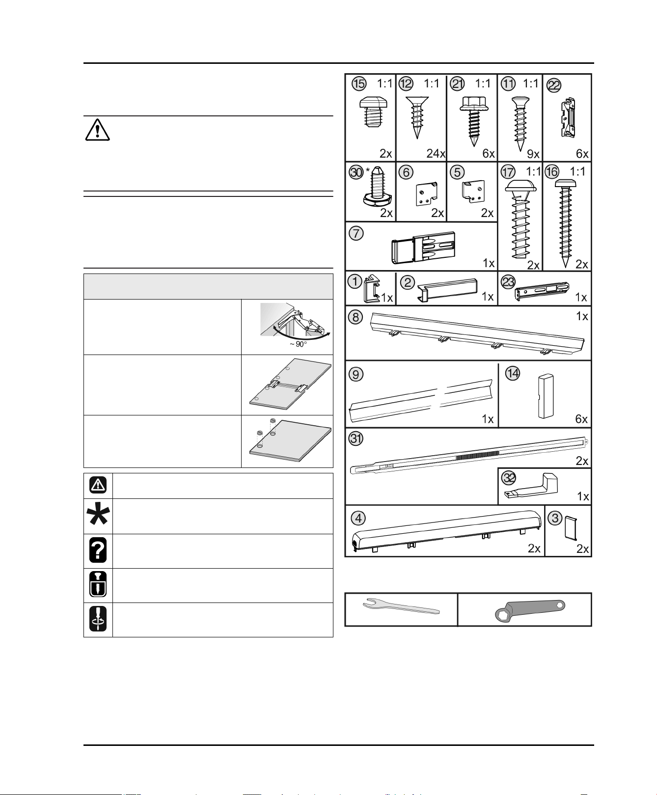
The following assembly parts are supplied with the appliance:
Fig. 18
The following tools are supplied with the appliance:
Fig. 19
The following tool is also required:
12 * Depending on model and options
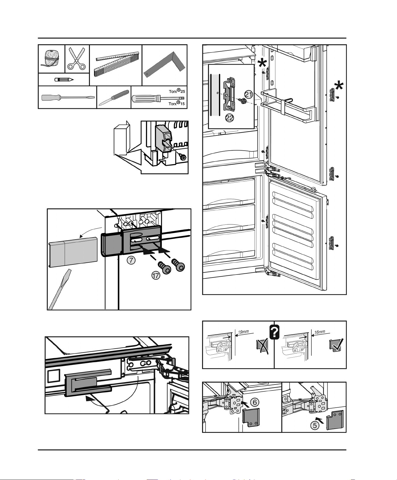
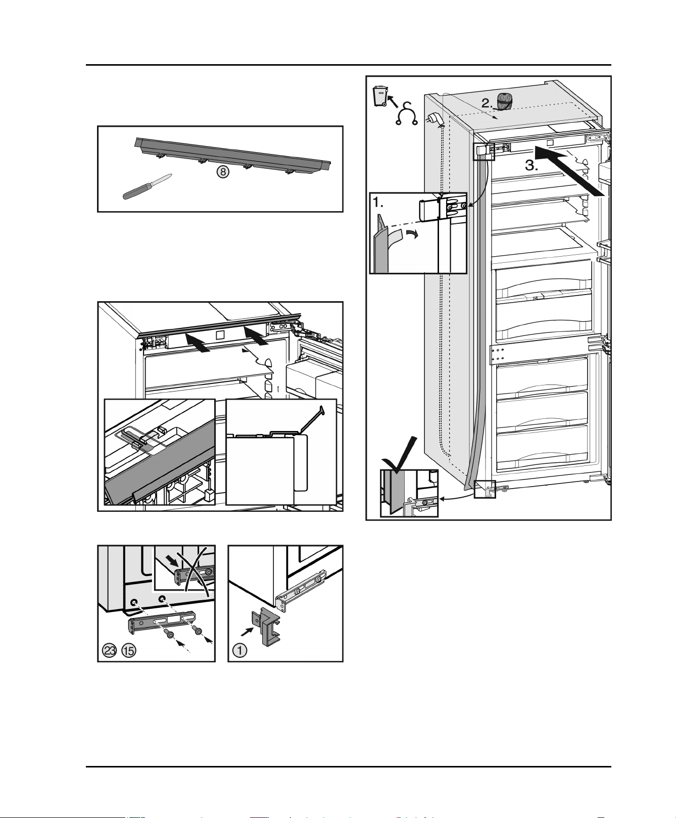
Fig. 20
If the depth of the unit is
less than 21-3/4 in.
(553 mm) remove the
spacers on the back of the
appliance in order to be
able to push the appliance
completely into the recess.
Removing the spacers may
cause the appliance to use
more energy as this
reduces the ventilation
cross-section.
Undo the screw and remove the spacers.
u
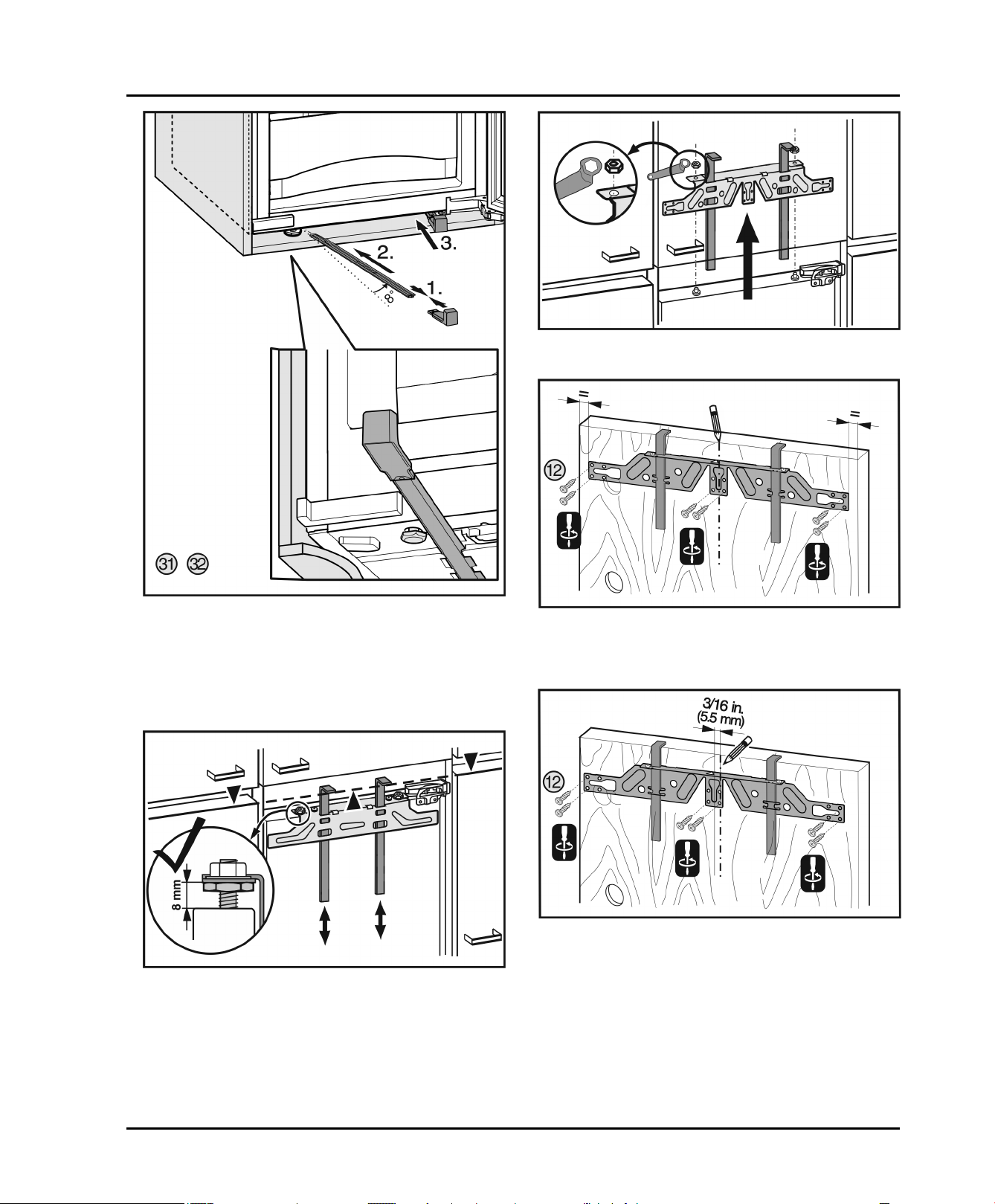
Installing the appliance in the recess.
Fig. 23
Fitting spring steel brackets. If the fridge section door is
u
Fig. 21
Remove the top left cover and screw the fixing bracket
u
in loosely.
Fig. 22
Take off cover.
u
* Depending on model and options 13
large use two pairs of spring steel brackets.
Fig. 24
Fig. 25
Installing the appliance in the recess.
With 5/8 in. (16 mm) thick cabinet side panels:
clip spacers on all hinges.
u
Remove the top left cover and screw the fixing bracket
u
in loosely.
Fig. 26
With a 22 3/4 in. (578 mm) wide recess:
cut the equalizer trim on the hinge side with a knife to fit
u
the groove.
With a 22 in. (560 mm) wide recess:
cut the equalizer trim on both sides with a knife to fit the
u
groove.
Fig. 27
Fit the equalizer trim to the top of the appliance.
u
Fig. 28
Fasten the bottom left fixing bracket so that it does not
u
protrude beyond the side panel.
Clip the stop onto the bracket.
u
14 * Depending on model and options
Fig. 29
Fit the strip: place at the top under the bracket and stick
u
to the side panel. The strip must not be shortened.
Remove the mains cable cleat and run the cable
u
upwards using a thread.
Push the appliance two thirds into the cabinet.
u
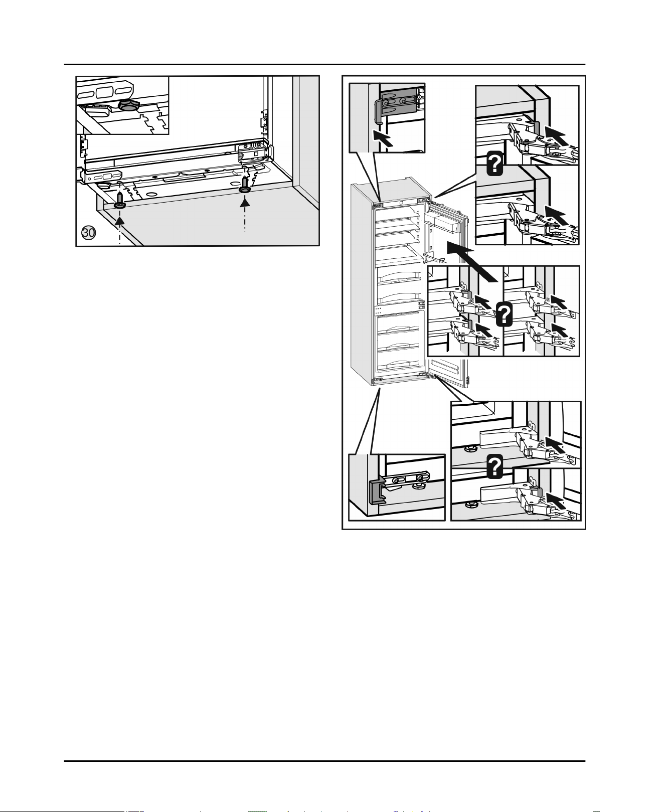
Fig. 30
Fit the adjusting feet to the bottom of the appliance
u
floor.
Installing the appliance in the recess.
Fig. 31
Push the appliance in until the handle side above the
u
bracket and below the stop meets the front of the
cabinet side panel. With 5/8 in. (16 mm)thick cabinet
side panels the spacers on the hinge side must abut at
the same time. With 5/8 in. (16 mm)thick cabinet side
panels align the front edges of the hinges so that they
are flush with the front of the cabinet side panel.
* Depending on model and options 15
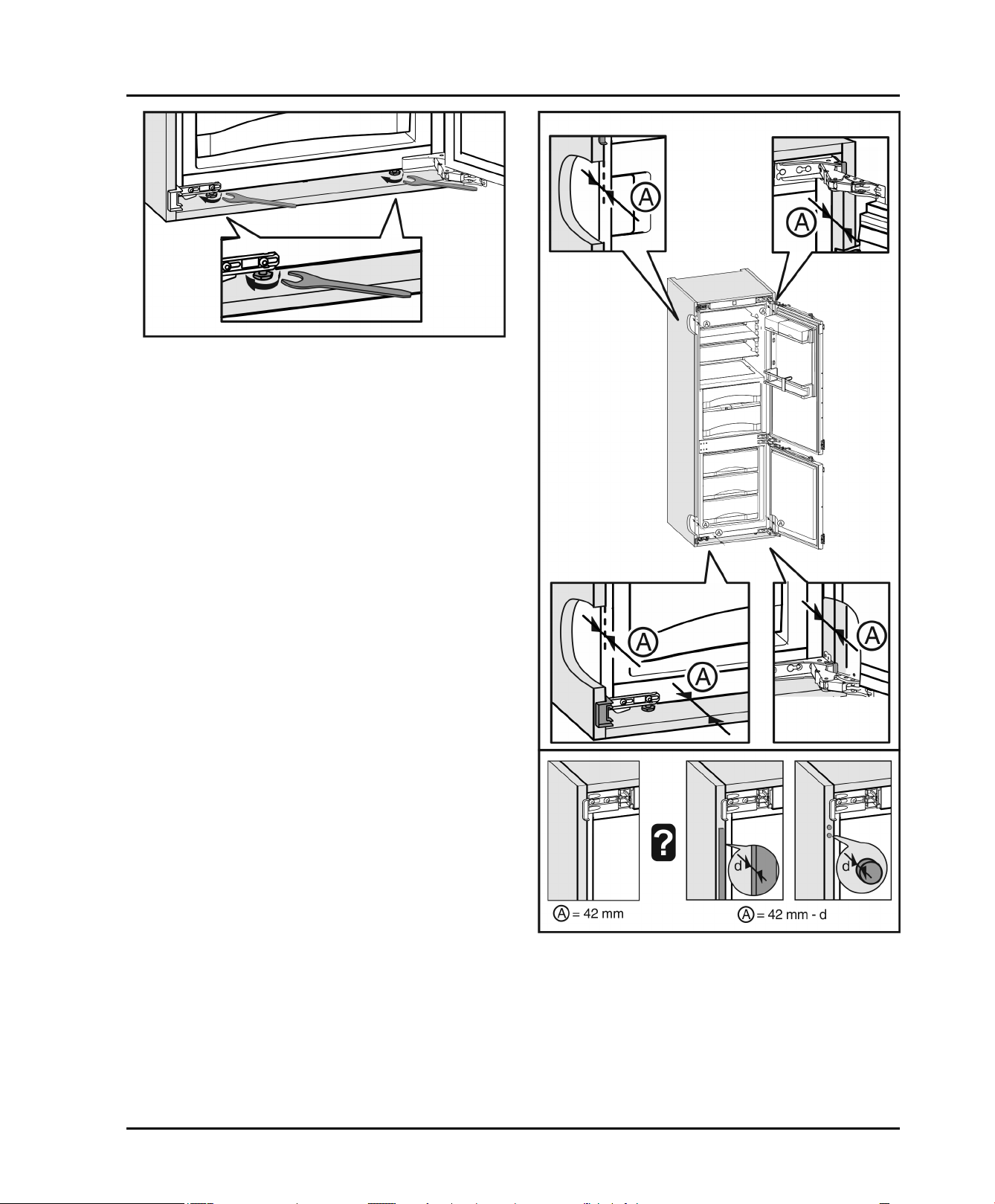
Installing the appliance in the recess.
Fig. 32
If necessary align the appliance using the adjusting
u
feet.
Fig. 33
Checking the insertion depth (A): The distance
u
between the front edge of the cabinet and the appliance body must be 1-21/32 '' (42 mm) all the way
along. If necessary make allowance for the stops on
the cabinet (d).
16 * Depending on model and options
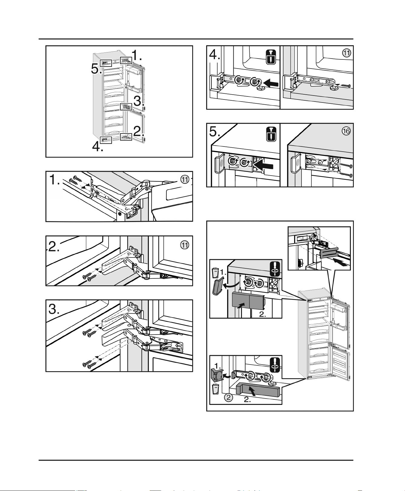
Fig. 34
Installing the appliance in the recess.
Fig. 38
Fig. 39
To fix the appliance in the recess: first hinge side up,
u
then down, then in the middle. Then handle side down
and finally handle side up.
Fig. 35
Fig. 36
Fig. 37
Fig. 40
Remove the stop from the bracket on the handle side
u
and dispose of it. Re-attach cover.
Re-attach the cover on the hinge side.
u
Break the stop at the bottom of the handle side off and
u
dispose of it. Fitting the cover.
* Depending on model and options 17
Installing the appliance in the recess.
u
Fig. 43
Undo the counter nuts and remove the crosspiece.
Fig. 41
Supporting the appliance at the bottom at the back:
u
Insert the handle into the stabilization rail and push the
stabilization rail into the appliance floor. Remove the
handle and do the same with the second stabilization
rail.
Carry out the steps below for both doors:
Fig. 42
Close the door.
u
Check the default setting of 5/16 in. (8 mm).
u
Raise fitting aids to unit door height. Bottom stop edge
u
of the fitting aid = top edge of the door to be fitted.
Fig. 44
Hang crosspiece on the inside of the unit door.
u
With a 22 in. (560 mm) wide recess:
align the crosspiece to the middle of the door.
u
Fig. 45
With a 22 3/4 in. (578 mm) wide recess:
align the crosspiece to the middle of the door and then
u
3/16 (5.5 mm) move towards the hinge side.
With chipboard doors fit the crosspiece with at least 6
u
screws and at least 4 screws for frame and panel
doors.
18 * Depending on model and options
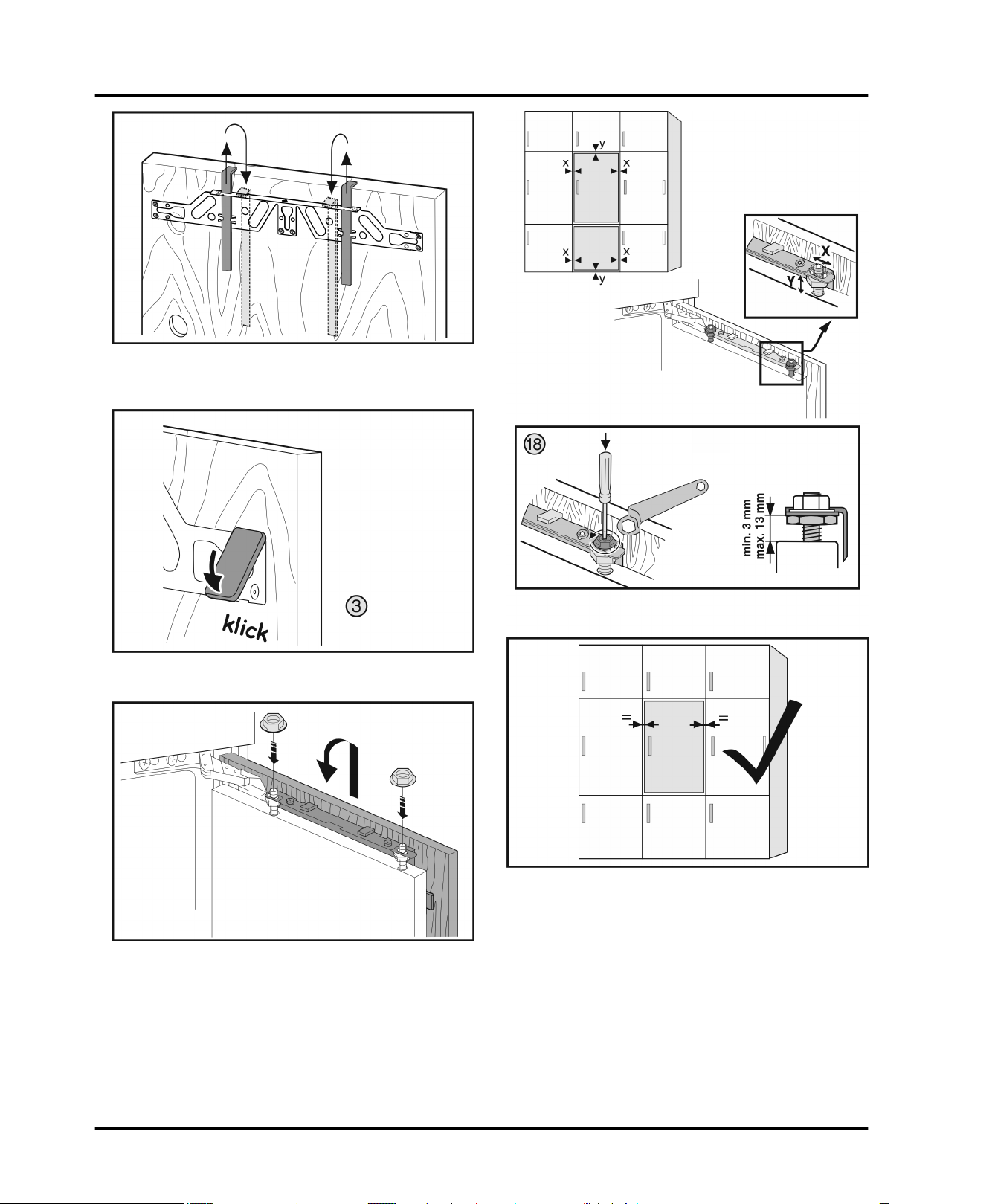
Fig. 46
Remove the fitting aids, turn round and insert into the
u
adjacent opening.
Installing the appliance in the recess.
Fig. 47
Clip the cover on the crosspiece on the handle side.
u
Fig. 48
Attach the unit door and loosely screw the lock nuts
u
onto the adjusting bolts.
Fig. 49
Align the unit door in the X and Y direction using the
u
adjusting bolts.
Tighten the lock nuts.
u
* Depending on model and options 19
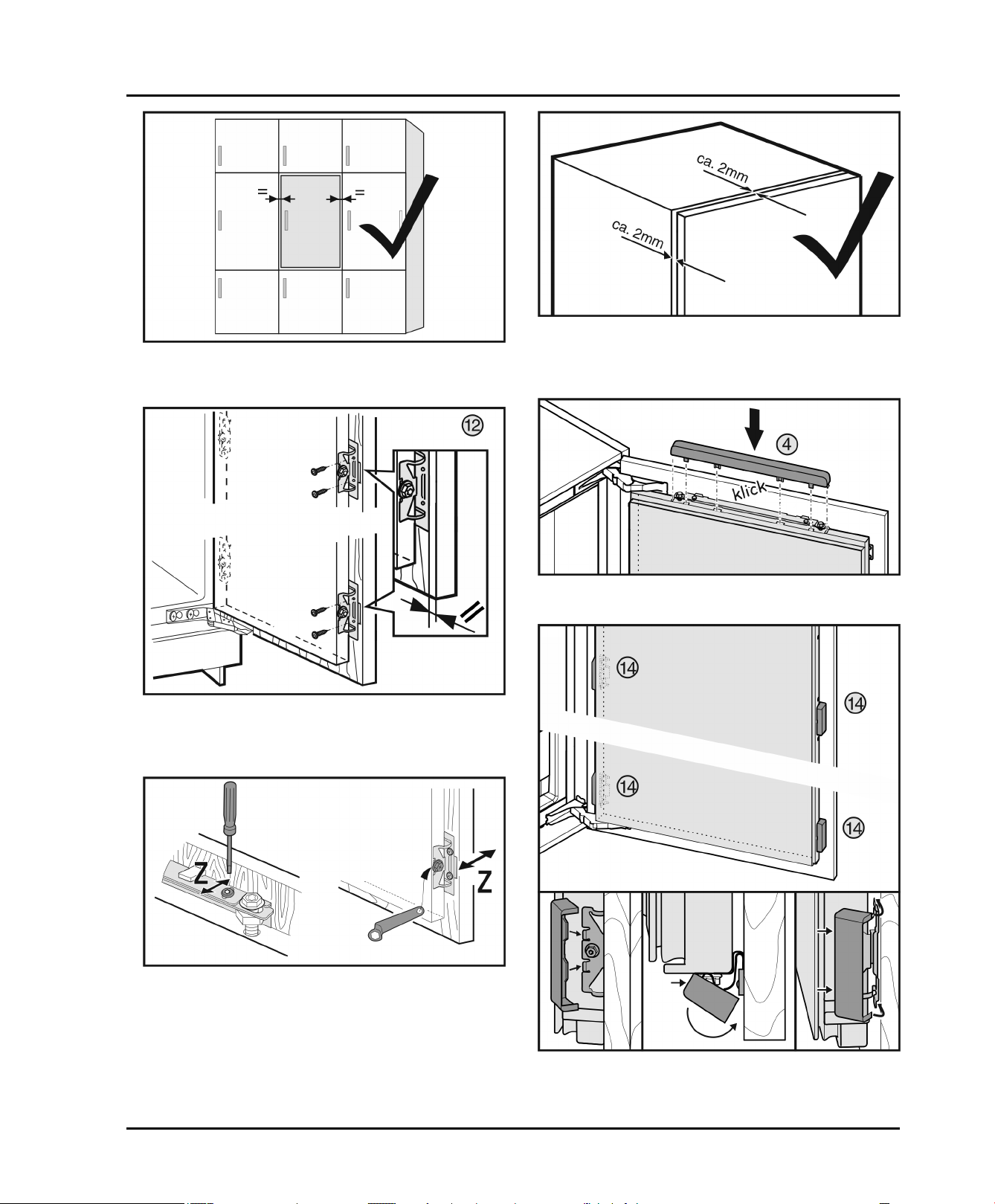
Installing the appliance in the recess.
Fig. 50
Check the gap between the door and the surrounding
u
unit doors
u
u
Fig. 53
Check the distance between the unit door and the unit
body.
Check all screws and retighten if necessary.
Fig. 51
Align the front edge of the spring steel bracket parallel
u
to the unit door edge and screw the bracket down
tightly.
Fig. 52
Aligning the unit door in the Z direction: Undo the
u
adjusting screw on the crosspiece and the screw on the
spring steel bracket then move the door.
Fig. 54
Clip the top cover on.
u
Fig. 55
20 * Depending on model and options
Put the cover onto the spring steel bracket, fasten at
u
the front, swivel towards the back and let it engage at
the top and bottom.
Fig. 56
Check the following points to make sure the appliance is
installed correctly. Otherwise, icing up, the formation of
condensate and malfunctions may occur:
The door must close properly.
w
The unit door must not touch the body of the unit.
w
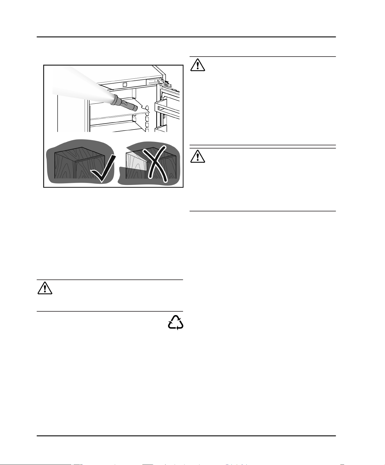
The seal on the upper corner on the handle side must
w
be fitted securely. To verify this, darken the room, place
a flashlight in top part of the appliance and close the
door. If you see light shining out, check the assembly.
10 Disposal of packaging
WARNING
Danger of suffocation from packaging materials and films!
Do not allow children to play with packaging materials.
u
The packaging is made from recyclable materials:
Corrugated card/cardboard
Parts made of foamed polystyrene
Films and bags from polyethylene
Packing bands from polypropylene
Wood frame nailed together with a polyethylene
window*
Take the packaging material to an official collection
u
point.
Disposal of packaging
11 Connecting the appliance
WARNING
Electrical shock hazard!
Start-up should only take place once the appliance has
u
been installed according to these instructions.
Electrically ground appliance.
u
Do not ground to a gas pipe.
u
Check with a qualified electrician if you are not sure the
u
appliance is properly grounded.
Do not have a fuse in the neutral or grounding circuit.
u
Do not use an extension cord, power bar or a multiple
u
socket adapter.
Do not use a power cord that is frayed or damaged.
u
WARNING
Electrical shock hazard!
This appliance is equipped with a three-prong (grounding)
polarized plug for your protection against possible shock
hazards. Electrical Grounding Required.
Do not remove the round grounding prong from the
u
plug.
Use only an grounded adapter.
u
Wait 1 hour after installation before you plug in the
appliance. This allows the refrigerant and system lubrication to reach equilibrium.
Make sure incoming voltage is the same as the appli-
ance rating. A 110-120 Volt, 60 Hz, 15 Amp electrical
supply (20 Amp for side-by-side installations) circuit
that is controlled by a circuit breaker or fuse is required.
We recommend using a dedicated circuit for this appli-
ance to prevent electrical overload.
Follow all Federal, State and local electrical, fire and
building codes and ordinances when installing the
receptacle and / or the appliance.
In some communities, a wall switch is required to turn
power to the appliance ON and OFF.
To reduce the risk of fire, electric shock, or personal
injury, installation work and electrical wiring must be
done by a qualified electrician in accordance with all
applicable codes and standards, including fire-rated
construction.
The Power Plug must be easily accessible so that the
appliance can be disconnected from the mains quickly
in an emergency. It must not be behind the back of the
appliance.
The top of the electric outlet must be located within
82-5/8 in. (2100 mm) from the top of the base in the
cabinet.
* Depending on model and options 21
 Loading...