

Page 1

Design Guide
Fully Integrated Models 24" and 48"
Release 07 2015
Page 2

Page 3

Welcome
Liebherr is one of the World’s leading Manufacturers of Premium Refrigeration. For more than 60 years,
Liebherr has specialized in developing and manufacturing first class refrigerators and freezers as well as
wine cabinets. We focus on performance and efficiency as well as keeping food fresher longer.
Produced in Austria and Germany, Liebherr has a full line of premium models tailored specifically for the
North American marketplace to fit any design vision you have for your kitchen.
Our freestanding stainless models are sleek centerpieces that make a definite statement. Our built-in
models are perfect for designs that call for units that slide into cabinet surrounds. And our fully-integrated
models become one with your kitchen design, hidden seamlessly behind your custom cabinetry.
High quality materials, perfectly detailed finishes, precise electronic control systems, elite cooling components, variable speed compressors and the latest production processes ensure energy efficiency and
performance for years to come.
Our superior products offer premium quality, cutting edge design and innovative features that fit with your
busy lifestyle.
Page 4

Introduction
LIEBHERR WARRANTY PLAN
FULL TWO YEAR WARRANTY - For two years from the date of original purchase, your Liebherr Warranty
covers all parts and labor to repair or replace any part of the product which proves to be defective in materials or workmanship.
FULL FIVE YEAR WARRANTY - For five years from the date of original purchase, your Liebherr Warranty
covers all parts and labor to repair or replace any components that prove to be defective in materials or
workmanship in the sealed system. The "Sealed System" means only the compressor, condenser, evaporator, drier and all connecting tubing.
LIMITED 6TH THROUGH 12TH YEAR WARRANTY - From the 6th through 12th year from the date of
original purchase, your Liebherr Warranty covers all parts that prove to be defective in materials or workmanship in the sealed system (parts only).
For Service and Parts in the U.S.:
PlusOne Solutions, Inc.
Customer Service
If your appliance is not working properly, or if the temperature display reads "F0" to "F9 ”, please call the
numbers listed below.
Give the fault number displayed, together with the
Type Designation,
Service Number and
Appliance Number (Serial Number)
from the model plate, to ensure prompt, accurate servicing. The model plate is located inside the appliance.
3501 Quadrangle Blvd, Suite 120
Orlando, FL 32817
Toll Free: 1-866-LIEBHER or
1-866-543-2437
Service-appliances.us@liebherr.com
www.liebherr-appliances.com
Leave the appliance door closed until the customer service technician arrives to minimize any further cold loss.
For Service and Parts in Canada:
Euro-Parts Canada
39822 Belgrave Road,
BELGRAVE, Ontario, N0G 1E0
Phone: (519) 357-3320
Fax: (519) 357-1326
Toll Free: 1-888-LIEBHER or
1-888-543-2437
www.euro-parts.ca
Need help?
For design related inquiries not addressed in this Design
Guide please email install.americas@liebherr.com
Page 5

Contents
General Remarks
I. Safety Warnings .......................................................................................................................................7
II. Electrical Requirements & Safety .......................................................................................................... 8
III. IceMaker (if equipped) ........................................................................................................................... 8
IV. Area Requirements .................................................................................................................................9
V. Safety Regulations .................................................................................................................................. 9
Fully Integrated Models 24" and 48" Models
24" Model: HC 1030, HC 1050B, HC 1070, HC 1080, HC 1021/ HCB 1060, SBS 6613 .......................... 10
Ventilation Requirements ........................................................................................................................ 14
Kitchen Cabinet Base Grille .................................................................................................................... 15
Location Of The Electrical Outlet ............................................................................................................ 15
Unit Dimensions ...................................................................................................................................... 16
Kitchen Cabinet Doors ............................................................................................................................ 17
Definition of the Door Panel Heights ....................................................................................................... 18
HC 1030, HC 1050B, HC 1070, HC 1080, HC 1021/ HCB 1060, SBS 6613 .............................................. 19
Kitchen cabinet setup for the water filter ............................................................................................... 20
24" Model: HC 1000B, HC 1001B .............................................................................................................. 22
Ventilation Requirements ........................................................................................................................ 24
Kitchen Cabinet Base Grille .................................................................................................................... 25
Location Of The Electrical Outlet ............................................................................................................ 25
Unit Dimensions ...................................................................................................................................... 26
Kitchen Cabinet Doors ............................................................................................................................ 27
Definition of the Door Panel Heights ....................................................................................................... 28
HC 1000B, HC 1001B ............................................................................................................................. 29
24" and 48" Models: HF 861 / HRB 1120, SBS 70I4 ................................................................................. 30
Ventilation Requirements ........................................................................................................................ 32
Kitchen Cabinet Base Grille .................................................................................................................... 33
Location Of The Electrical Outlet ............................................................................................................ 33
Unit Dimensions ...................................................................................................................................... 34
Kitchen cabinet setup for the water filter ................................................................................................ 35
Kitchen Cabinet Doors ............................................................................................................................ 36
Definition of the Door Panel Heights ....................................................................................................... 37
HF 861 / HRB 1120 ................................................................................................................................. 37
Page 6

Page 7
General Remarks
I. Safety Warnings
PLEASE READ AND FOLLOW THESE INSTRUCTIONS
This design guide contains Warning and Caution statements. This information is important for safe and
efficient installation.
This design guide is not replacing the use and care manual which contains important information on how to use Liebherr appliances.
Always read and follow all Warning and Caution statements!
indicates a hazardous situation, which if not avoided, will result in death or serious injury.
indicates a hazardous situation, which if not avoided, could result in death or serious injury.
indicates a hazardous situation, which if not avoided, will result in minor or moderate injury.
NOTICE
indicates a hazardous situation, which if not avoided, could result in damage to property.
NOTE
indicates useful advice and tips.
Make sure incoming voltage is the same as the unit rating.
To reduce the risk of fire, electric shock, or personal injury, the installation work and electrical wiring must be done by
a qualified electrician in accordance with all applicable codes and standards, including fire rated construction.
To the Installer
It is very important that the guidelines and instructions are followed in this design guide to ensure proper installation and operation of the unit. The Installation Guidelines section contains important information for making sure the
installation is correct. Read and understand all the information and installation guidelines in this manual before the
unit is installed.
It is also very important to know the Safety Information.
7
Page 8
General Remarks
II. Electrical Requirements & Safety
Circuit has to be grounded and protected by a circuit
breaker or fuse.
Single installation: Side-by-side installation:
• 115 volt • 115 volt
• 60 hz • 60 hz
• 15 amp • 20 amp
We recommend using a dedicated circuit for each
appliance to prevent circuit overload and the chance of
interruption to the appliance.
The appliances are equipped with a three-prong
(grounding) polarized plug for protection against possible
shock hazards.
Comply with the National Electrical Code as well as local
codes and ordinances when installing the receptacle.
Do not ground to a gas pipe. Check with a
qualified electrician if you are not sure the
appliance is properly grounded. Do not have
a fuse in the neutral or grounding circuit.
III. IceMaker (if equipped)
The icemaker is located in the freezer compartment.
The appliance must be level for the icemaker to function
properly.
If you have hard water, we recommend you install a
water softener. Also, a filter must be installed if the water
contains solids such as sand. All equipment and devices
used to supply the water to the appliance must comply
with the current regulations for your geographical area.
Safety Instructions and Warnings
• Do not attach the water source while the appliance is
connected to an electrical outlet.
• The water quality must comply with the drinking water
regulations for the geographical area where the appliance is located.
• The icemaker is designed exclusively to make ice
cubes in quantities needed by a household and may
only be operated with water appropriate for this purpose.
• All repairs and work on the icemaker may only be done
by customer service personnel or other trained personnel.
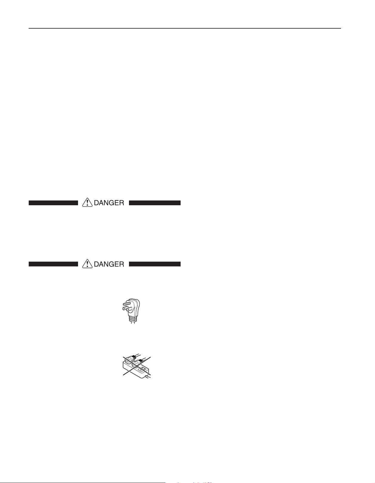
Electrocution hazard.
Electrical Grounding Required.
• Do not remove the round grounding prong
from the plug.
• Do not use a two-prong
grounding adapter.
• Do not use an extension cord to connect
power to the unit.
• Do not use a power cord that is frayed or
damged.
• Do not use a power strip.
Failure to follow these instructions may
result in fire, electrical shock or death.
8
Appliances with water connection:
• The water pressure must be between 21.8-87.0 psi (1.5-6
bar). Use a 1/4" OD copper line (not supplied) to connect the water supply to the solenoid valve.
• A shut-off valve, must be installed between the hose
line and the main water supply so that the water supply can be stopped if necessary. Do not install the
shut-off valve behind the refrigeration unit.
• The connection to the water supply may only be made
by a trained and licensed plumber.
• The manufacturer cannot accept liability for damage
caused by equipment or water lines between the solenoid valve and the water supply.
Appliances with water tank:
• Fill the water tank with cold potable water only. Never
use fluids containing sugar such as soft drinks, fruitjuices etc..
• Through the use of filtered, decarbonized water, drinking water with the best possible flavor is achieved,
and this can be used for problem-free production of
ice cubes. This water quality can be achieved using
a table water filter of the kind available in trade retail
outlets.
Page 9
General Remarks
IV. Area Requirements
Verify the following:
• Floors can support refrigerator’s weight plus approximately 1200 pounds (544 kg) of food weight. Not
all Liebherr products are designed for 1200 pounds
(544 kg) of food. Some units are smaller and total
weights may vary.
• Finished kitchen floor height is level. Refrigerator must
be shimmed to the floor level, or levelled, to make
sure, air vents are not obstructed.
• Remove anything attached to the rear or side walls
that can obstruct refrigerator opening.
• Cutout dimensions are accurate.
• Electrical outlet is in correct location.
Do not install this unit next to any other refrigerator or
freezer except another Liebherr model. Liebherr models
are designed to allow side by side installation. They are
equipped with a heating system to eliminate condensation when units are installed side by side. Installing this
unit next to any other refrigerator or freezer can cause
condensation or cause damage to the Liebherr unit.
NOTICE
To protect the refrigerator from possible
damage, allow the appliance to stand 1/2 to
1 hour in place before turning the electricity
on. This allows the refrigerant and system
lubrication to reach equilibrium.
V. Safety Regulations
The appliance complies with UL250 and CAN/CSA-C
22,2 No. 63-93 (HF 851, HRB 1110) and respectively
CAN/CSA-C22.2 No. 60335-1-11, 60335-2-24-06 and
UL 60335-1, UL 60335-2-24 (HC 1070, HC 1000B, HC
1001B, HRB 1120) and is designed to cool, freeze, store
food as well as make ice (if equipped). It is designed as a
household appliance. If used commercially, the relevant
regulations on commercial use must be observed.
The appliance is set to operate within specific ambient
temperature limits according to its climate rating. These
temperature limits should not be exceeded. The correct climate rating for your appliance is indicated on the
model plate.
This is explained as follows:
Climate
Rating
SN 50°F to 90°F (10°C to 32°C)
N 61°F to 90°F (16°C to 32°C)
ST 61°F to 101°F (16°C to 38°C)
T 61°F to 110°F (16°C to 43°C)
SN-ST
SN-T
Refrigerant circuits are tested for leaks.
Set for Ambient Temperatures of
50°F to 101°F (10°C to 38°C)
50°F to 110°F (10°C to 43°C)
9
Page 10
Fully Integrated
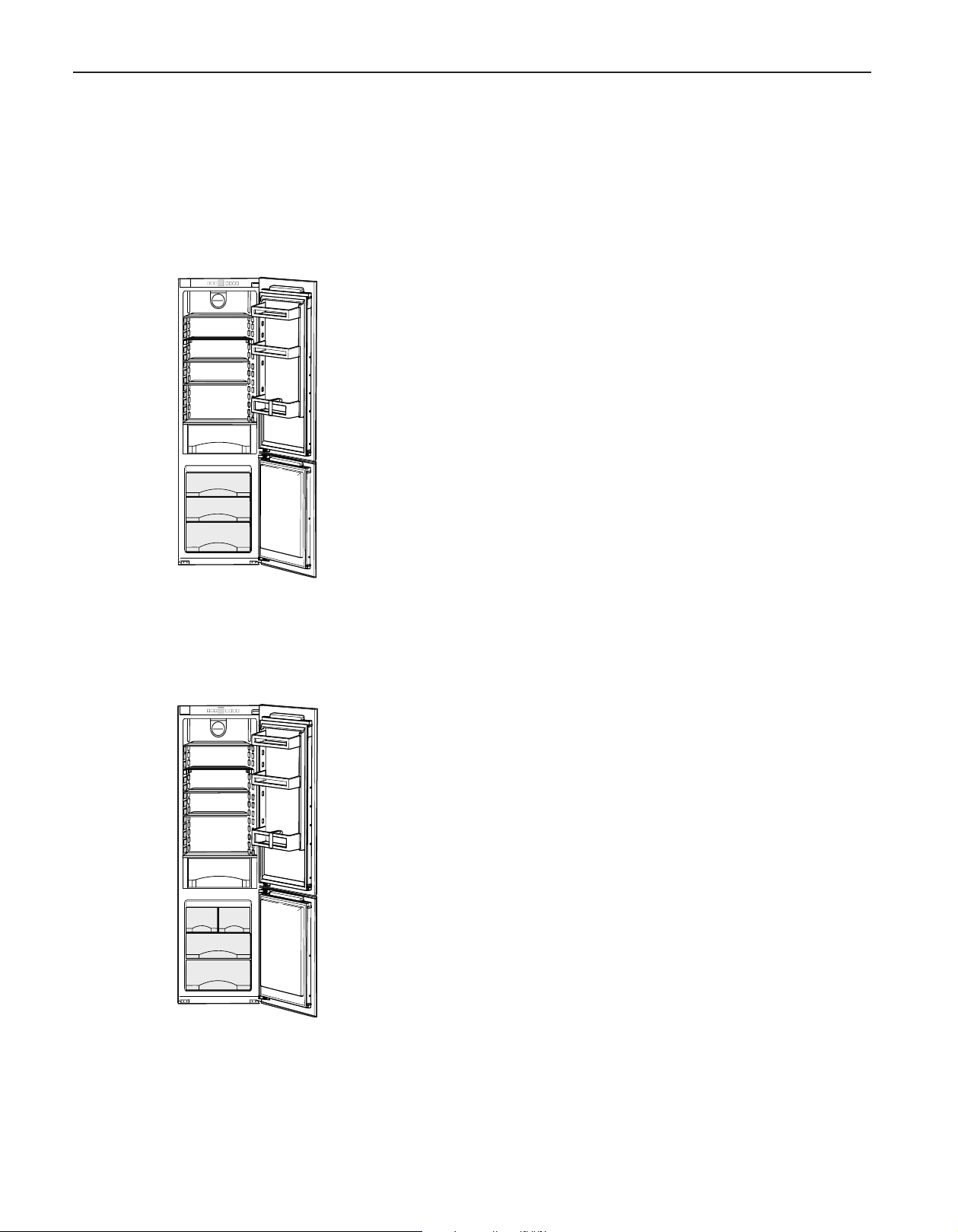
24" Model: HC 1030, HC 1050B, HC 1070, HC 1080, HC 1021/ HCB 1060, SBS 6613
24" Model: HC 1030, HC 1050B, HC 1070, HC 1080, HC 1021/ HCB 1060, SBS 6613
Integrated units are the most stylish option available - they're totally out of sight, fully concealed behind a cabinet door. Installed in
a tall kitchen cupboard, the refrigerator door simply opens in unison with the cupboard door.
HC 1030
Energy Star: certified
Energy consumption p. a.: 395* kWh
respectively 395** kWh
Energy Supply: 115V/60Hz
Total capacity: 9,42 cu ft (267 L)
Refrigerator: 7,02 cu ft (199 L)
Freezer: 2,4 cu ft (68 L)
Climate Rating: SN-T
Door hinges: right / reversable
• Automatic refrigerator and freezer compartment defrosting
• LED light
• Height-adjustable feet at front and levelling rails
• Changeable door gasket
HC 1050B
Energy Star: certified
Energy consumption p. a.: 475* kWh
respectively 407** kWh
Energy Supply: 115V/60Hz
Total capacity: 9,42 cu ft (267 L)
Refrigerator: 7,02 cu ft (199 L)
Freezer: 2,4 cu ft (68 L)
Climate Rating: SN-T
Door hinges: right / reversable
• Automatic refrigerator and freezer compartment defrosting
• LED light
• IceMaker with fixed water connection
• Height-adjustable feet at front and levelling rails
• Changeable door gasket
* Measurement determined according to Appendix A to Subpart B of 10 CFR Part 430
** Measurement determined according to Appendix A1 to Subpart B1 of 10 CRF Part 430
10
Page 11
Fully Integrated
24" Model: HC 1030, HC 1050B, HC 1070, HC 1080, HC 1021/ HCB 1060, SBS 6613
HC 1070
Energy Star: certified
Energy consumption p. a.: 475* kWh
respectively 407** kWh
Energy Supply: 115V/60Hz
Total capacity: 9,32 cu ft (264 L)
Refrigerator: 6,92 cu ft (196 L)
Freezer: 2,4 cu ft (68 L)
Climate Rating: SN-T
Door hinges: right / reversable
• Automatic refrigerator and freezer compartment defrosting
• LED light column
• HC 1070 with soft closing system
• IceMaker with water tank
• Height-adjustable feet at front and levelling rails
• Changeable door gasket
HC 1080
Energy Star: certified
Energy consumption p. a.: 475* kWh
respectively 407** kWh
Energy Supply: 115V/60Hz
Total capacity: 9,39 cu ft (266 L)
Refrigerator: 6,99 cu ft (198 L)
Freezer: 2,4 cu ft (68 L)
Climate Rating: SN-T
Door hinges: right / reversable
• Automatic refrigerator and freezer compartment defrosting
• LED light column
• HC 1080 with soft closing system
• IceMaker with fixed water connection
• Height-adjustable feet at front and levelling rails
• Changeable door gasket
11
Page 12
Fully Integrated
24" Model: HC 1030, HC 1050B, HC 1070, HC 1080, HC 1021/ HCB 1060, SBS 6613
HC 1021
Energy Star: certified
Energy consumption p. a.: 395* kWh
respectively 395** kWh
Energy Supply: 115V/60Hz
Total capacity: 9.39 cu ft (266 L)
Refrigerator: 6.99 cu ft (198 L)
Freezer: 2,4 cu ft (68 L)
Climate Rating: SN-T
Door hinges: left / reversable
• Automatic refrigerator and freezer compartment defrosting
• LED light column
• HC 1021 with soft closing system
• Height-adjustable feet at front and levelling rails
• Changeable door gasket
HCB 1060
Energy Star: certified
Energy consumption p. a.: 475* kWh
respectively 403** kWh
Energy Supply: 115V/60Hz
Total capacity: 8.71 cu ft (247 L)
Refrigerator: 3.91 cu ft (111 L)
BioFresh: 2.4 cu ft (68 L)
Freezer: 2.4 cu ft (68 L)
Climate Rating: SN-ST
Door hinges: right / reversable
• Automatic refrigerator and freezer compartment defrosting
• LED light column
• HCB 1060 with soft closing system
• BioFresh safes with SoftTelescopic
• IceMaker with fixed water connection
• Height-adjustable feet at front and levelling rails
• Changeable door gasket
* Measurement determined according to Appendix A to Subpart B of 10 CFR Part 430
** Measurement determined according to Appendix A1 to Subpart B1 of 10 CRF Part 430
12
Page 13

Fully Integrated
24" Model: HC 1030, HC 1050B, HC 1070, HC 1080, HC 1021/ HCB 1060, SBS 6613
SBS 6613 (HC1021 & HCB 1060)
Energy Supply: 115V/60Hz
Total capacity: 18.10 cu ft (513 L)
Refrigerator: 10.90 cu ft (309 L)
BioFresh: 2.4 cu ft (68 L)
Freezer: 4.8 cu ft (132 L)
Ice cube capacity: 1.7 lb/24h
Ice cube stock: 3.3 lb/24h
Climate Rating: SN-T/SN-ST
Door hinges: left / right
• Automatic refrigerator and freezer compartment defrosting
• Automatic IceMaker can be switched off
• With soft closing system and LED light column
• Height-adjustable feet at the front and levelling rails
• Changeable door gasket
13
Page 14

Fully Integrated
Ventilation Requirements
24" Model: HC 1030, HC 1050B, HC 1070, HC 1080, HC 1021/ HCB 1060, SBS 6613
This is a fully integrated refrigerator-freezer which means that it
is fully enclosed by a kitchen cabinet. This type of cabinet must
be carefully constructed using the correct dimensions and it
must provide suitable ventilation to ensure proper appliance
operation.
NOTICE
If the following ventilation dimensions are
not observed the compressor will be damaged.
Kitchen Cabinet Airflow
1. The following ventilation dimensions must be observed:
There must be a ventilation space at least 31 in.² (200 cm²)
at the airflow inlet (1) and at the airflow outlet (2).
The top ventilation space can be directed in one of the following ways:
A) Directly over the appliance (2) with either an optional factory air vent or custom made one.
B) Above the cabinet and below the ceiling (3).
C) Through a vent installed in a soffit (4).
B - Side view
Cabinet
Refrigerator
A
B
C
A minimum space of 1 1/2" is required when a cabinet is built
above and/or underneath.
14
Page 15

Fully Integrated
24" Model: HC 1030, HC 1050B, HC 1070, HC 1080, HC 1021/ HCB 1060, SBS 6613
Kitchen Cabinet Base Grille Location Of The Electrical Outlet
Ventilation through the cabinet base at the bottom can be
achieved by installing the provided ventilation grille (3) or via a
ventilation opening of at least 31 in.² (200 cm²).
When using the provided ventilation grille (3), please proceed
as follows:
- In the cabinet base, cut out a ventilation opening that is 1723/32 in. (450 mm) in width and 2-7/32 in. (56 mm) in height.
- Insert ventilation (3) grille into the cabinet base cut-out (1).
- From the back side, slide the snap-fits (2) into the grille until
the hooks make contact with the cabinet base.
- Completely mount cabinet base (with ventilation grille and
snap-fits) to kitchen cabinet.
Do not locate the electrical outlet behind the
appliance!
The electrical outlet is required to be accessible for
installation and service.
Choose the position of the
electrical outlet considering
these specifications.
Free length of the power cord
is 85".
Power cord exits rear of appliance at this location.
15
Page 16

Fully Integrated
Unit Dimensions
24" Model: HC 1030, HC 1050B, HC 1070, HC 1080, HC 1021/ HCB 1060, SBS 6613
A 21-7/16" (544 mm)
B 69-11/16" (1770 mm)
C 22" (559 mm)
D 69-3/4" - 70-3/8" (1772 - 1788 mm)
E min 22" (560 mm)
max 22-3/4" (578 mm)
G 21-5/8" (550 mm)
H 1-5/8" (40 mm)
J 27-3/8" (695 mm)
K 24-3/4" (629 mm)
L max. 3/4" (19 mm)
M 9-21/32" (245 mm)
In the case of side-by-side installation, two appliances next to one another,
build the appliances into separate kitchen units.
1 Power cord
2 Level
3 Fish line for power cord
4 3" of the cabinet needs to be finished
as it can be seen when th door is open
16
Page 17

Fully Integrated
24" Model: HC 1030, HC 1050B, HC 1070, HC 1080, HC 1021/ HCB 1060, SBS 6613
Kitchen Cabinet Doors
Designing the Kitchen Cabinet Doors
You will need two doors for the kitchen cabinet, one on top for
the refrigerator compartment, and one on the bottom for the
freezer compartment. In general, the doors have these characteristics:
• The width of the cabinet doors depends on the kitchen style
and the size of the gaps between the door panels of the
cabinetry. Generally, a 1/8” vertical gap between the cabinet
doors is recommended.
• The doors should be at least 5/8 in. (16 mm) thick to allow
the connecting rails to be fastened to them. The maximum
thickness of the door panel can be 3/4 in. (19mm).
• With both doors closed, there should be a minimum of 1/8
in. (3 mm) between the upper and lower doors (2). Also, there
should be a 1/8 in. (3 mm) clearance between the upper door
and the cabinet door (1) above it (if any).
• The top edge of the upper door (1) and lower door (2) should
be even with the doors of adjoining cabinet(s), if any.
• The position of the joint between the kitchen cabinet doors
must be level with the position of the joint between the appliance doors (2).
• Adjust the door alignment before installing the appliance. It is
impossible to adjust the door with the appliance installed.
• Check the installation dimensions according to Section "Unit
Dimensions".
• Do not load the door with more than 35 lbs (16kg) of food.
• Before assembling the unit door, make sure that the permitted weight for the unit doors is not exceeded. If permitted
weight is exceeded damage to hinges may occur.
Maximum weight of unit door
Fridge compartment door
Freezer compartment door
30.5 lbs (14 kg)
26.5 lbs (12 kg)
17
Page 18

Fully Integrated
24" Model: HC 1030, HC 1050B, HC 1070, HC 1080, HC 1021/ HCB 1060, SBS 6613
Definition of the Door Panel Heights
1. Start with the lower door of the freezer compartment:
The freezer door height is 24-24/32" (629 mm). In order to
cover the lower part of the appliance, increase the height of
the panel to 27-3/8" (695 mm).
2. To cover the face side of the floor board (a) add the thickness of the floor board (usually 3/4" (19 mm)).
Thus, the minimum height of the freezer door panel is:
27-3/8" + 3/4" = 28-1/8"
(695 mm + 19 mm = 714 mm)
3. Without door panels on the unit, there is a gap of 19/32“
(15mm) between the hinge on the freezer door and the
hinge on the refrigerator door.
After the installation of the cabinet doors, the gap between
the two doors will only be around 1/8” (3mm).
4. If there is other furniture standing close to the refrigerator
cabinet (See also previous page) this furniture typically has
a gap between two drawers or two doors. Depending on
your kitchen, these gaps are approximately 1/8" (3 mm)
wide.
5. In this case, the maximum height of the freezer door panel is:
27-3/8" + 3/4" + 19/32" - 1/8" = 28-19/32"
(695 mm + 19 mm + 15 mm - 3 mm = 726 mm)
Where as the minimum height of the freezer door panel is:
27-3/8" + 3/4" = 28-1/8"
(695 mm + 19 mm = 714 mm)
Of course, the final door height depends on the gap position of
the cabinets that stand to the left and right of the refrigerator
cabinet.
6. The height of the refrigerator door panel is:
The total opening of the cabinet (i.e. 70-3/8" (1788 mm)) plus
the thickness of the top as well as the floor board (usually 3/4"
(19 mm)) minus the height of the freezer door panel (xxx" (xxx
mm)) and subtract the width of the gap (approximately 1/8" (3
mm)):
70-3/8" + 3/4" + 3/4" - xxx" - 1/8" = 71-3/4" - xxx"
(1788 mm + 19 mm + 19 mm - xxx mm - 3 mm = 1823mm –
xxx mm)
18
Page 19

Fully Integrated
HC 1030, HC 1050B, HC 1070, HC 1080, HC 1021/ HCB 1060, SBS 6613
HC 1030, HC 1050B, HC 1070, HC 1080, HC 1021/ HCB 1060, SBS 6613
(The numbers in brackets are mm)
Cabinet Doors
Appliance
(a) The base of the cabinet can be thickened to raise the the
top of the lower door panel to counter height. Lower panel
will have to be increased in length by the same amount.
The gap between refrigerator and freezer door must lie within the
crosshatched area.
19
Page 20

Fully Integrated
Kitchen cabinet setup for the water filter
The water filter module can be purchased from your Liebherr
retailer or distributor for the models HC 1050B, HC 1080 and
HCB 1060.
It should be installed near the appliance in the cabinet, for
example, in the adapter cabinet above the appliance. To connect the filter to the appliance, it may be necessary to make an
opening (C) in the floor of the adapter cabinet through which
the hoses will be routed.
The maximum length of the water hose is 98-7/16 ‘‘ (2.5 m).
The filter cover must be installed during assembly to leave sufficient space around the filter module.
HC 1030, HC 1050B, HC 1070, HC 1080, HC 1021/ HCB 1060, SBS 6613
Maintain the dimensions shown in Fig. so that the filter
can be replaced and the cover can be removed.
(A) 13/16in (20mm)
(B) 3-15/16in (100mm)
(C) 1-3/16in. x 3/8in. ( 30mm x10mm)
(D) min. 4in (100mm)
20
Page 21

Fully Integrated
HC 1030, HC 1050B, HC 1070, HC 1080, HC 1021/ HCB 1060, SBS 6613
21
Page 22

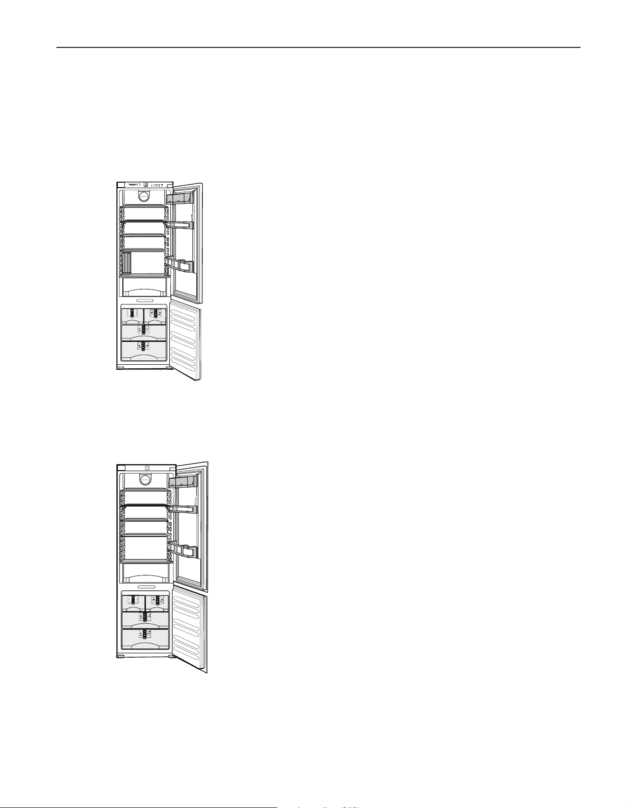
Fully Integrated
24" Model: HC 1000B, HC 1001B
24" Model: HC 1000B, HC 1001B
Integrated units are the most stylish option available - they're totally out of sight, fully concealed behind a cabinet door. Installed in
a tall kitchen cupboard, the refrigerator door simply opens in unison with the cupboard door.
HC 1000B
Energy Star: certified
Energy consumption p. a.: 395 kWh
Energy Supply: 115V/60Hz
Total capacity: 9,42 cu ft (267 L)
Refrigerator: 7,02 cu ft (199 L)
Freezer: 2,4 cu ft (68 L)
Climate Rating: SN-T
Door hinges: right / reversable
• Automatic refrigerator and freezer compartment defrosting
• HC 1000B with Sliding system and LED-lighting
• Height-adjustable feet at front and levelling rails
HC 1001B
Energy Star: certified
Energy consumption p. a.: 395 kWh
Energy Supply: 115V/60Hz
Total capacity: 9,42 cu ft (267 L)
Refrigerator: 7,02 cu ft (199 L)
Freezer: 2,4 cu ft (68 L)
Climate Rating: SN-T
Door hinges: left / reversable
• Automatic refrigerator and freezer compartment defrosting
• HC 1001B with Sliding system and LED-lighting
• Height-adjustable feet at front and levelling rails
22
Page 23

Fully Integrated
24" Model: HC 1000B, HC 1001B
23
Page 24

Fully Integrated
Ventilation Requirements
24" Model: HC 1000B, HC 1001B
This is a fully integrated refrigerator-freezer which means that it
is fully enclosed by a kitchen cabinet. This type of cabinet must
be carefully constructed using the correct dimensions and it
must provide suitable ventilation to ensure proper appliance
operation.
NOTICE
If the following ventilation dimensions are
not observed the compressor will be damaged.
Kitchen Cabinet Airflow
1. The following ventilation dimensions must be observed:
There must be a ventilation space at least 31 in.² (200 cm²)
at the airflow inlet (1) and at the airflow outlet (2).
The top ventilation space can be directed in one of the following ways:
A) Directly over the appliance (2) with either an optional factory air vent or custom made one.
B) Above the cabinet and below the ceiling (3).
C) Through a vent installed in a soffit (4).
A
B - Side view
Cabinet
Refrigerator
B
C
A minimum space of 1 1/2" is required when a cabinet is built
above and/or underneath.
24
Page 25

Fully Integrated
24" Model: HC 1000B, HC 1001B
Kitchen Cabinet Base Grille Location Of The Electrical Outlet
Ventilation through the cabinet base at the bottom can be
achieved by installing the provided ventilation grille (3) or via a
ventilation opening of at least 31 in.² (200 cm²).
When using the provided ventilation grille (3), please proceed
as follows:
- In the cabinet base, cut out a ventilation opening that is 1723/32 in. (450 mm) in width and 2-7/32 in. (56 mm) in height.
- Insert ventilation (3) grille into the cabinet base cut-out (1).
- From the back side, slide the snap-fits (2) into the grille until
the hooks make contact with the cabinet base.
- Completely mount cabinet base (with ventilation grille and
snap-fits) to kitchen cabinet.
Do not locate the electrical outlet behind the
appliance!
The electrical outlet is required to be accessible for
installation and service.
Choose the position of the
electrical outlet considering
these specifications.
Free length of the power cord
is 85".
Power cord exits rear of appliance at this location.
25
Page 26

Fully Integrated
Unit Dimensions
24" Model: HC 1000B, HC 1001B
A 21-7/16" (544 mm)
B 69-11/16" (1770 mm)
C 21-1/4" (540 mm)
D 69-3/4" - 70-3/8" (1772 - 1788 mm)
E min 22" (560 mm)
max 22-3/4" (578 mm)
G 21-5/8" (550 mm)
H 1-5/8" (40 mm)
J 26-3/8" (669 mm)
K 24-3/4" (629 mm)
L max. 3/4" (19 mm)
M 6-11/16" (170 mm)
In the case of side-by-side installation, two appliances next to one another,
build the appliances into separate kitchen units.
1 Power cord
2 Level
3 Fish line for power cord
4 3" of the cabinet needs to be finished
as it can be seen when th door is open.
26
Page 27

Fully Integrated
Kitchen Cabinet Doors
Designing the Kitchen Cabinet Doors
You will need two doors for the kitchen cabinet, one on top for
the refrigerator compartment, and one on the bottom for the
freezer compartment. In general, the doors have these characteristics:
• The width of the cabinet doors depends on the kitchen style
and the size of the gaps between the door panels of the
cabinetry. Generally, a 1/8” vertical gap between the cabinet
doors is recommended.
• The doors should be at least 5/8 in. (16 mm) thick to allow
the connecting rails to be fastened to them. The maximum
thickness of the door panel can be 3/4 in. (19mm).
• With both doors closed, there should be a minimum of 1/8
in. (3 mm) between the upper and lower doors (2). Also, there
should be a 1/8 in. (3 mm) clearance between the upper door
and the cabinet door (1) above it (if any).
• The top edge of the upper door (1) and lower door (2) should
be even with the doors of adjoining cabinet(s), if any.
24" Model: HC 1000B, HC 1001B
• The position of the joint between the kitchen cabinet doors
must be level with the position of the joint between the appliance doors (2).
• Adjust the door alignment before installing the appliance. It is
impossible to adjust the door with the appliance installed.
• Check the installation dimensions according to Section "Unit
Dimensions".
• Do not load the door with more than 35 lbs (16kg) of food.
27
Page 28

Fully Integrated
Definition of the Door Panel Heights
1. Start with the lower door of the freezer compartment:
The freezer door height is 24-24/32" (663 mm). In order to
cover the lower part of the appliance, increase the height of
the panel to 26-3/8" (669 mm).
2. To cover the face side of the floor board (a) add the thickness of the floor board (usually 3/4" (19 mm)).
Thus, the minimum height of the freezer door panel is:
26-3/8" + 3/4" = 27-1/8"
(669 mm + 19 mm = 688 mm)
3. Without door panels on the unit, there is a gap of 2 5/8“
(67mm) between the freezer door and the refrigerator door.
After the installation of the cabinet doors, the gap between
the two doors will only be around 1/8” (3mm).
4. If there is other furniture standing close to the refrigerator
cabinet (See also previous page) this furniture typically has
a gap between two drawers or two doors. Depending on
your kitchen, these gaps are approximately 1/8" (3 mm)
wide.
24" Model: HC 1000B, HC 1001B
5. In this case, the maximum height of the freezer door panel is:
26-3/8" + 3/4" + 2-5/8" - 1/8" = 29-5/8"
(669 mm + 19 mm + 67 mm - 3 mm = 752 mm)
Where as the minimum height of the freezer door panel is:
26-3/8" + 3/4" = 27-1/8"
(669 mm + 19 mm = 688 mm)
Of course, the final door height depends on the gap position of
the cabinets that stand to the left and right of the refrigerator
cabinet.
6. The height of the refrigerator door panel is:
The total opening of the cabinet (i.e. 70-3/8" (1788 mm)) plus
the thickness of the top as well as the floor board (usually 3/4"
(19 mm)) minus the height of the freezer door panel (xxx" (xxx
mm)) and subtract the width of the gap (approximately 1/8" (3
mm)):
70-3/8" + 3/4" + 3/4" - xxx" - 1/8" = 71-3/4" - xxx"
(1788 mm + 19 mm + 19 mm - xxx mm - 3 mm = 1823mm –
xxx mm)
28
Page 29

Fully Integrated
HC 1000B, HC 1001B
(The numbers in brackets are mm)
24" Model: HC 1000B, HC 1001B
Cabinet Doors
Appliance
(a) The base of the cabinet can be thickened to raise the the
top of the lower door panel to counter height. Lower panel
will have to be increased in length by the same amount.
The gap between refrigerator and freezer door must lie within the
crosshatched area.
29
Page 30

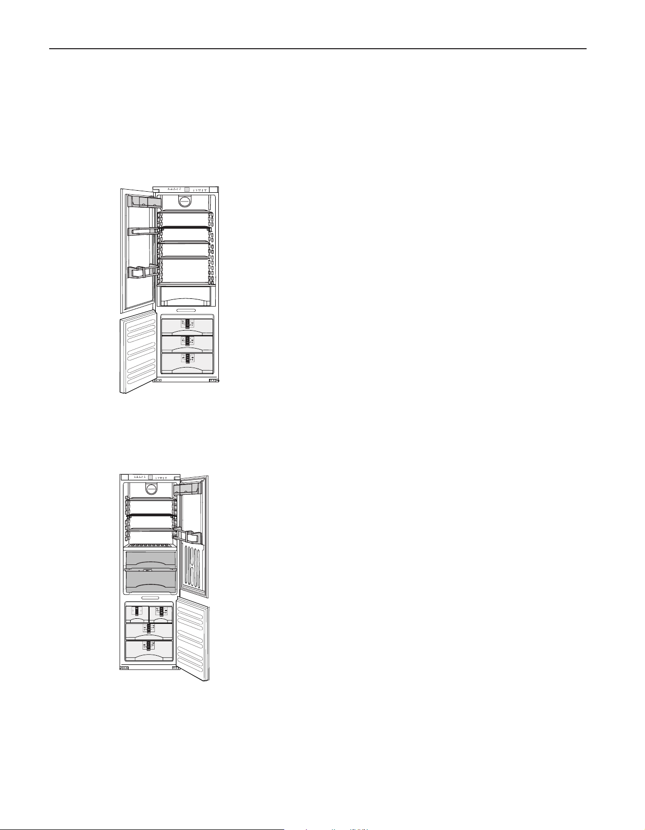
Fully Integrated
24" and 48" Models: HF 861 / HRB 1120, SBS 70I4
24" and 48" Models: HF 861 / HRB 1120, SBS 70I4
Integrated units are the most stylish option available - they're totally out of sight, fully concealed behind a cabinet door. Installed in
a tall kitchen cupboard, the refrigerator door simply opens in unison with the cupboard door.
HF 861
Energy Star: certified
Energy consumption p. a.: 439 kWh
Energy Supply: 115V/60Hz
Total capacity: 7.76 cu ft (220 L)
Climate Rating: SN-T
Door hinges: left / reversable
• Automatic freezer defrosting
• With soft closing system
• IceMaker with fixed water connection
• Height-adjustable feet at the front
• Changeable door gasket
HRB 1120
Energy Star: certified
Energy consumption p. a.: 283 kWh
Energy Supply: 115V/60Hz
Total capacity: 10,86 cu ft (308 L)
Refrigerator: 7,62 cu ft (216 L)
BioFresh: 3,24 cu ft (92 L)
Climate Rating: SN-ST
Door hinges: right / reversable
• With soft closing system
• LED light column at both sides
• BioFresh safes with SoftTelescopic
• Height-adjustable feet at front and levelling rails
• Changeable door gasket
30
Page 31

Fully Integrated
24" and 48" Models: HF 861 / HRB 1120, SBS 70I4
SBS 70I4 (HF 861 & HRB 1120)
Energy Supply: 115V/60Hz
Total capacity: 18.62 cu ft (528 L)
Refrigerator: 10.86 cu ft (308 L)
Freezer: 7.76 cu ft (220 L)
Ice cube capacity: 1.7 lb/24h
Ice cube stock: 3.3 lb/24h
Climate Rating: SN-T/SN-ST
Door hinges: left / right
• Automatic freezer defrosting
• Automatic IceMaker can be switched off
• With soft closing system and LED-lighting
• Height-adjustable feet at the front
• Changeable door gasket
31
Page 32

Fully Integrated
Ventilation Requirements
24" and 48" Models: HF 861 / HRB 1120, SBS 70I4
This is a fully integrated refrigerator-freezer which means that it
is fully enclosed by a kitchen cabinet. This type of cabinet must
be carefully constructed using the correct dimensions and it
must provide suitable ventilation to ensure proper appliance
operation.
NOTICE
If the following ventilation dimensions are
not observed the compressor will be damaged.
Kitchen Cabinet Airflow
1. The following ventilation dimensions must be observed:
There must be a ventilation space at least 31 in.² (200 cm²)
at the airflow inlet (1) and at the airflow outlet (2).
The top ventilation space can be directed in one of the following ways:
A) Directly over the appliance (2) with either an optional factory air vent or custom made one.
B) Above the cabinet and below the ceiling (3).
C) Through a vent installed in a soffit (4).
A
B - Side view
Cabinet
Refrigerator
B
C
A minimum space of 1 1/2" is required when a cabinet is built
above and/or underneath.
32
Page 33

Fully Integrated
24" and 48" Models: HF 861 / HRB 1120, SBS 70I4
Kitchen Cabinet Base Grille Location Of The Electrical Outlet
Ventilation through the cabinet base at the bottom can be
achieved by installing the provided ventilation grille (3) or via a
ventilation opening of at least 31 in.² (200 cm²).
When using the provided ventilation grille (3), please proceed
as follows:
- In the cabinet base, cut out a ventilation opening that is 1723/32 in. (450 mm) in width and 2-7/32 in. (56 mm) in height.
- Insert ventilation (3) grille into the cabinet base cut-out (1).
- From the back side, slide the snap-fits (2) into the grille until
the hooks make contact with the cabinet base.
- Completely mount cabinet base (with ventilation grille and
snap-fits) to kitchen cabinet.
Do not locate the electrical outlet behind the
appliance!
The electrical outlet is required to be accessible for
installation and service.
Choose the position of the
electrical outlet considering
these specifications.
Free length of the power cord
is 85".
Power cord exits rear of appliance at this location.
33
Page 34

Fully Integrated
Unit Dimensions
24" and 48" Models: HF 861 / HRB 1120, SBS 70I4
A 21-7/16" (544 mm)
B 69-11/16" (1770mm)
1 Power cord
2 Level
3 Fish line for power cord
C 22" (559 mm)
D 69-3/4" - 70-3/8" (1772 - 1788 mm)
E min 22" (560 mm)
max 22-3/4" (578 mm)
F 21-5/8" (550 mm)
G 1-5/8" (40 mm)
J 66-1/2" (1689,9 mm)
K max. 3/4" (19 mm)
L 9-21/32" (245 mm)
In the case of side-by-side installation, two appliances next to one another,
build the appliances into separate kitchen units.
34
4 3" of the cabinet needs to be finished
as it can be seen when th door is open.
Page 35

Fully Integrated
Kitchen cabinet setup for the water filter
The water filter module is supplied with the appliance (only
available for HF 861).
It should be installed near the appliance in the cabinet, for
example, in the adapter cabinet above the appliance. To connect the filter to the appliance, it may be necessary to make an
opening (C) in the floor of the adapter cabinet through which
the hoses will be routed.
The maximum length of the water hose is 98-7/16 ‘‘ (2.5 m).
The filter cover must be installed during assembly to leave sufficient space around the filter module.
24" and 48" Models: HF 861 / HRB 1120, SBS 70I4
Maintain the dimensions shown in Fig. so that the filter
can be replaced and the cover can be removed.
(A) 13/16in (20mm)
(B) 3-15/16in (100mm)
(C) 1-3/16in. x 3/8in. ( 30mm x10mm)
(D) min. 4in (100mm)
35
Page 36

Fully Integrated
Kitchen Cabinet Doors
Designing the Kitchen Cabinet Door
You will need one door for the kitchen cabinet. In general, the
door has these characteristics:
• The width of the cabinet door depends on the kitchen style
and the size of the gaps between the door panels of the
cabinetry. Generally, a 1/8 in. (3 mm) vertical gap between
the door panels is recommended.
• The door should be at least 5/8 in. (16 mm) thick to allow the
connecting rails to be fastened to it. The maximum thickness
of the door panel can be 3/4 in. (19mm).
• With closed door, there should be a minimum of 1/8 in. (3
mm) between the refrigerator door and the cabinet door (2)
above it (if any).
• The top edge of the door (1) should be even with the doors of
adjoining cabinet(s), if any.
• Adjust the door alignment before installing the appliance. It is
impossible to adjust the door with the appliance installed.
24" and 48" Models: HF 861 / HRB 1120, SBS 70I4
• Check the installation dimensions according to Section "Unit
Dimensions".
• Do not load the door of the refrigerator with more than 49,6
lbs (22,5kg) of food.
• Before assembling the unit door, make sure that the permitted weight for the unit door is not exceeded. If permitted
weight is exceeded damage to hinges may occur.
Maximum weight of unit door
Fridge door
Freezer door
50 lbs (23 kg)
50 lbs (23 kg)
36
Page 37

Fully Integrated
24" and 48" Models: HF 861 / HRB 1120, SBS 70I4
Definition of the Door Panel Heights
1 Cabinet door
2 Appliance door
The height of the cabinet door is calculated as follows:
Total cabinet height (i. e., 70-3/8 in. (1788 mm)) plus the thickness of the cover plate and floor plate Fig. 9 (a)
(usually 3/4 in. (19 mm)): 70-3/8 in. + 3/4 in. + 3/4 in. = 71-7/8 in. ( 1788 mm + 19 mm + 19 mm = 1826 mm )
HF 861 / HRB 1120
(The numbers in brackets are mm)
(a) The base of the cabinet can be thickened to raise the the
top of the lower door panel to counter height. Lower panel
will have to be increased in length by the same amount.
37
Page 38

Page 39

Page 40

Design Guide
Release 07 2015
 Loading...