

Page 1
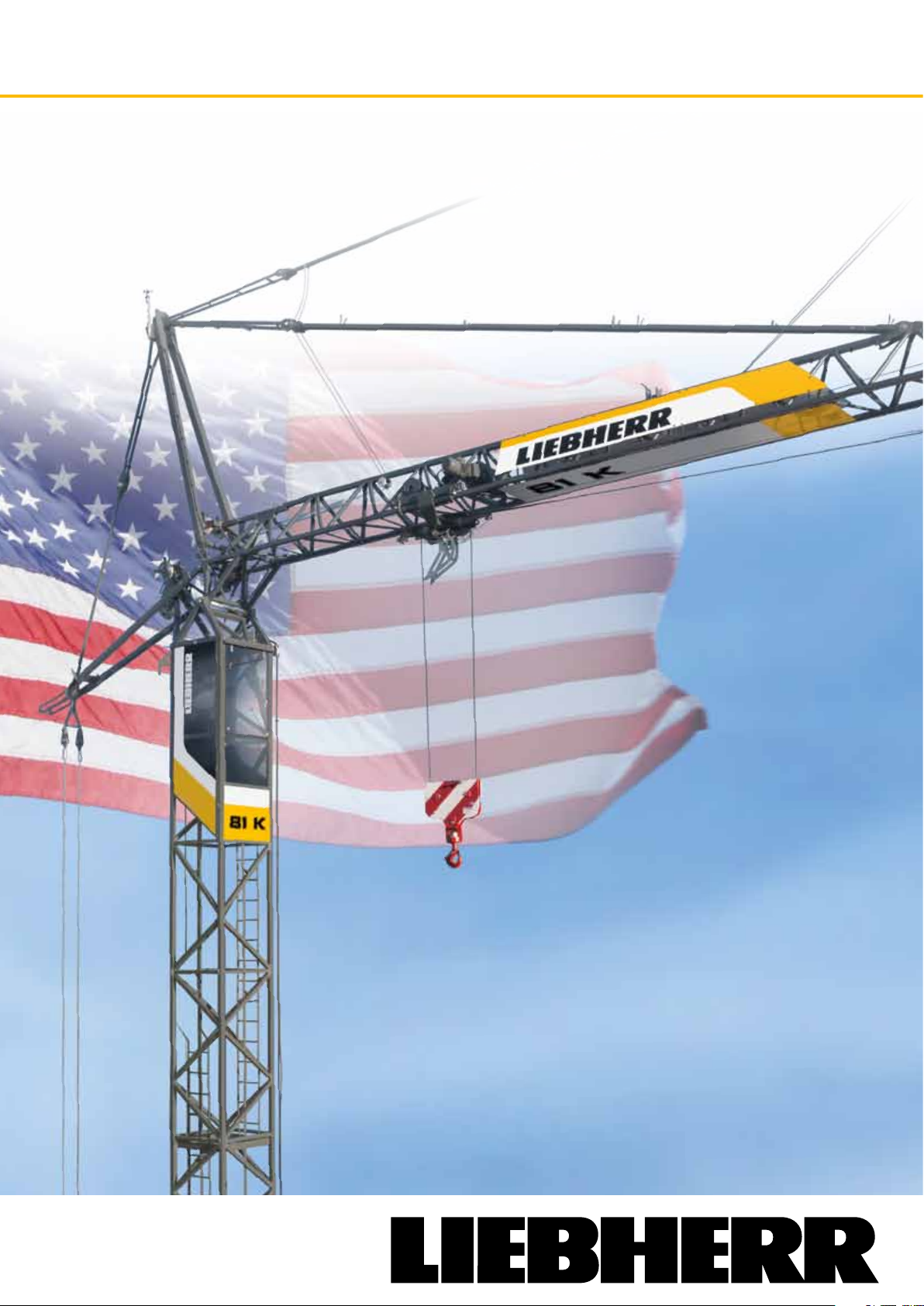
Fast-erecting crane 81 K
Max. lifting capacity: 13,230 lbs
Max. radius: 147’-6”
Lifting capacity with max. radius: 3,090 lbs
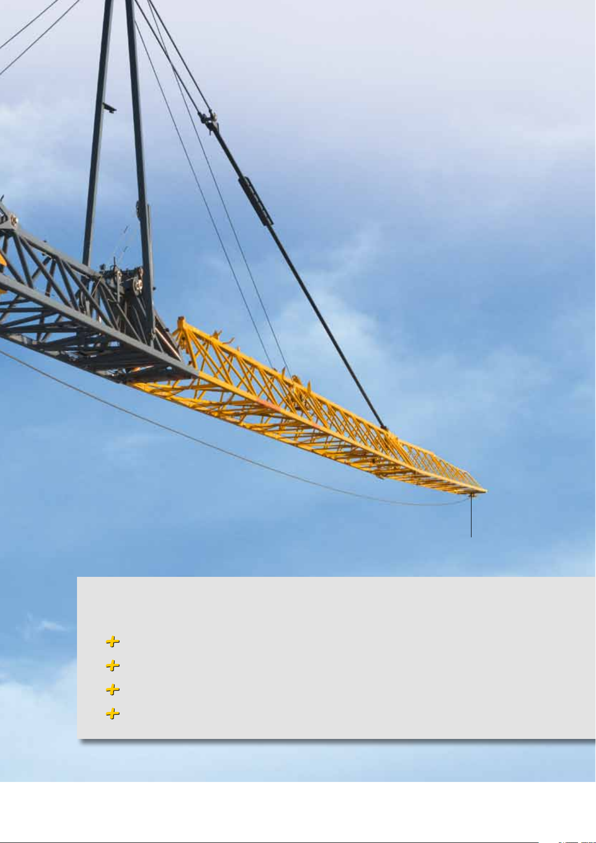
Works efficiently
and looks good
Page 2
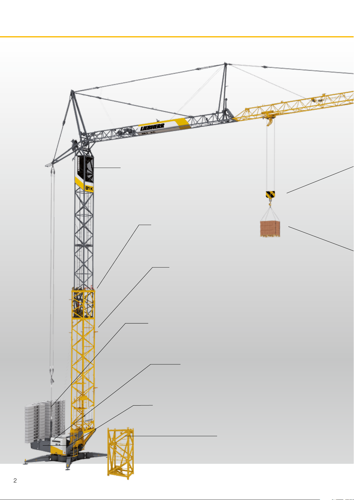
The 81 K fast-erecting crane.
Comfortable cab
with best possible view of the site
Torsionally resistant
Fully automatic play-free tower
connection
Integrated intermediate
hook heights
CC-Ballast
Saves time thanks to
boltable ballast slabs
New switch cabinet
Programmable logic control system, graphic display,
remote diagnosis, and much more besides.
Quick-Connection
for play-free connection of the
tower to the slewing platform
Variable slewing radius
9,02 - 11,48 ft
11 hook heights
Thanks to climbing capability
of tower sections
2
Page 3
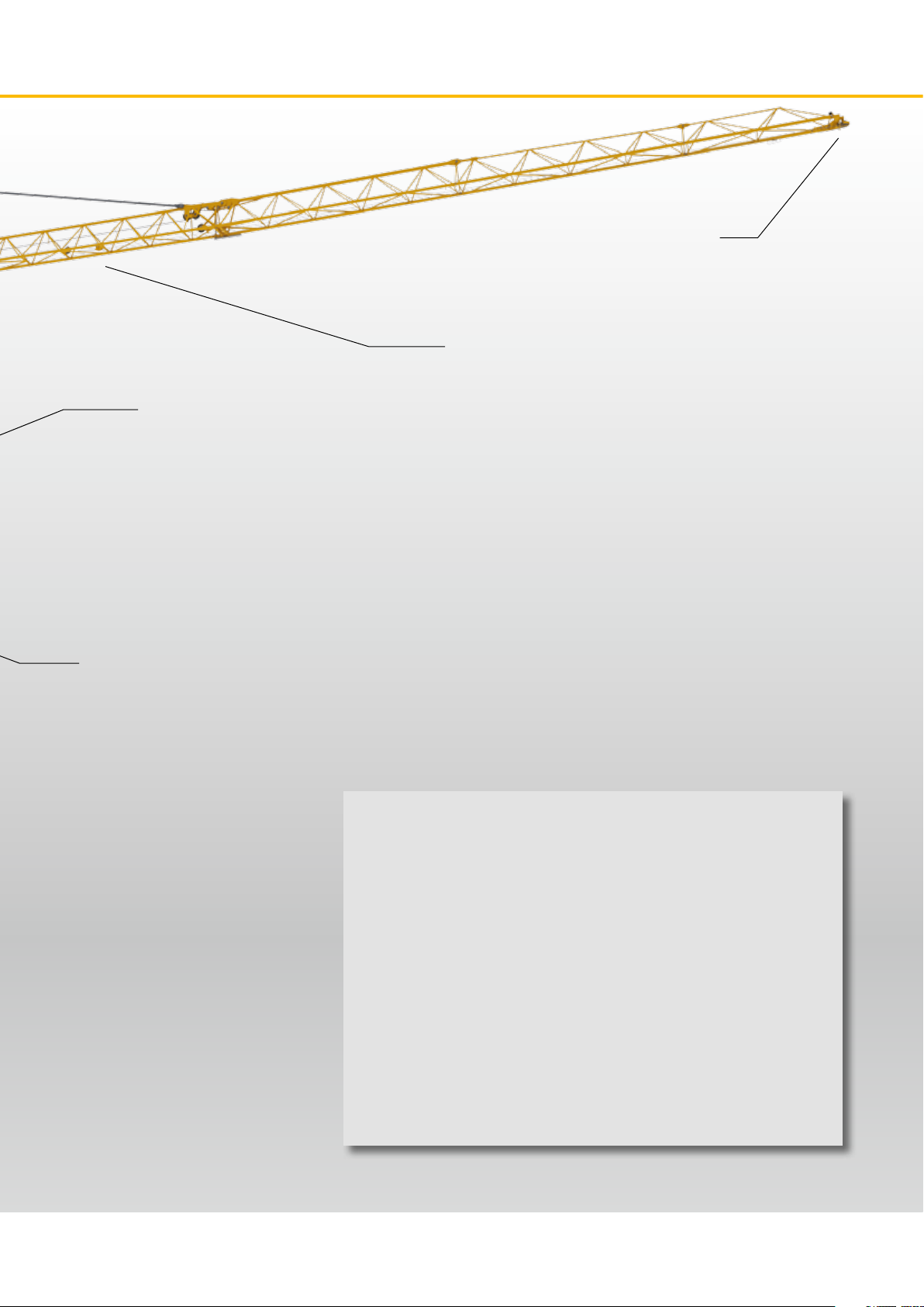
SPEED 2 LIFT
Pure two-line operation for
maximum handling capacity
MICROMOVE
Millimetric precision with
fine positioning
25% more
jib end lifting capacity
4 different
jib lenghts
Contents
Working fast and safe – for sure! Page 4
Our drive is your success. Page 10
Arrive efficiently. Page 16
Simply well set-up. Page 20
Assured long life – maintenance and more. Page 24
Technical Data. Page 28
Uses in summary. Page 31
3
Page 4
SPEED 2 LIFT
Always max. load and
full speed with two-line
operation
4
Page 5
147.6 ft / 3,090 lbs
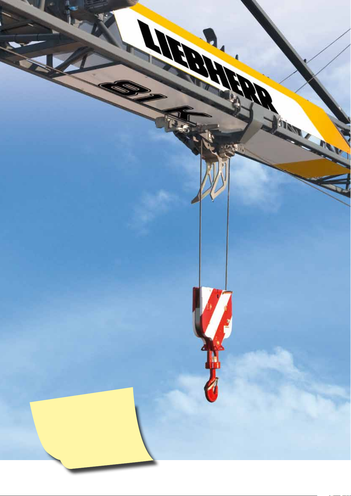
Working fast and safe – for sure!
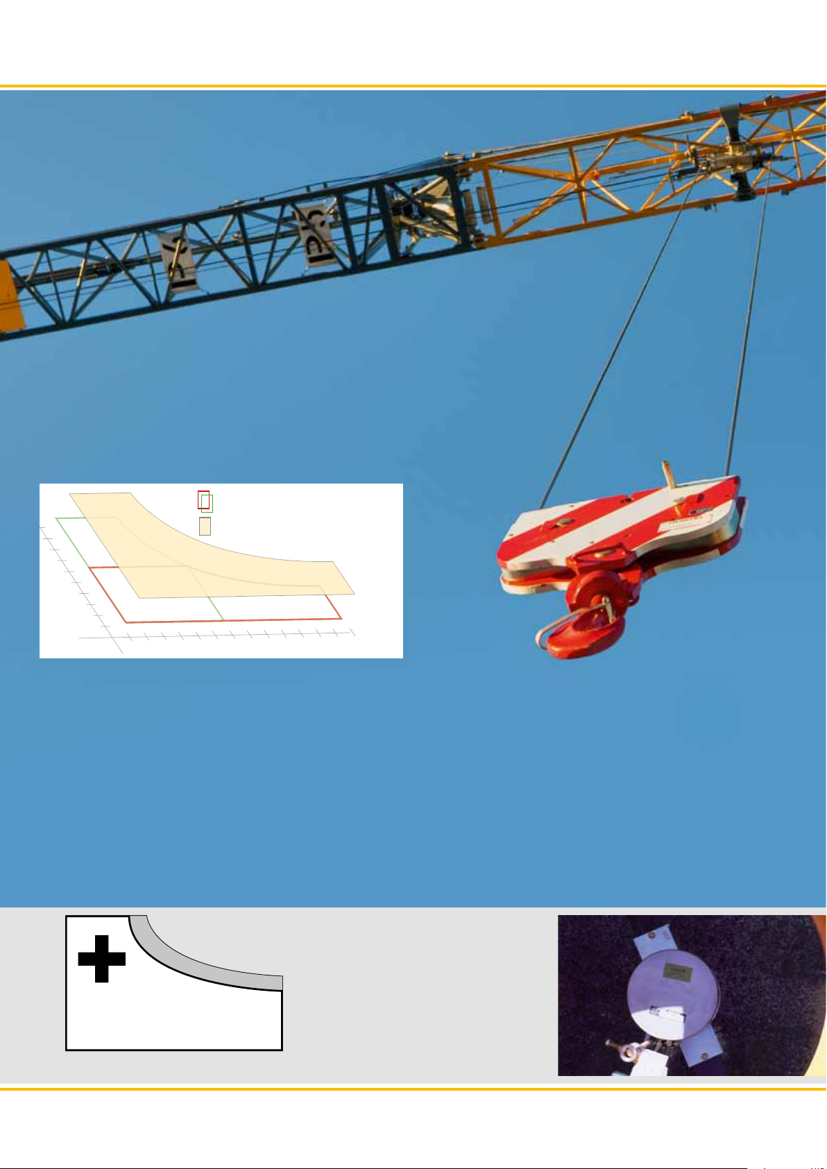
SPEED 2 LIFT: two-line operation for maximum performance at full speed
Unrivalled maximum lifting capacity
MICROMOVE: precision mode for millimetre precision positioning at the push of a button
Secure working movements with load swing damping and wind load control
5
Page 6
m/min
kg
Working fast and safe – for sure!
To date – Either fast or strong!
lb
New – Fast and strong.
ft/min
Rereeving – no longer required
The 81 K operates exclusively with two-line operation. Maximum performance at full speed – always! With hoists at
maximum lifting capacity and empty hook runs. Hoist speed
always matches the hanging load. By the way – half of all load
cycles are empty runs. We have increased the speed by 15%.
Strong matter
Currently up to 25% more
lifting capacity.
25 %
6
Page 7
Loads precisely positioned
With MICROMOVE, at the push of a button on the
control lever, lowering speed is reduced to micro levels. Even the heaviest loads can be precisely suspended and positioned without using the hoist gear
brakes.
Accurate against the wind
Wind influences the movement of the jib! With the wind
load control, the jib position is regulated automatically.
Counter measures are not necessary. Large-scale loads
(i.e. form panels) can be moved and suspended precise-
ly even in wind.
Steady handling
Fast turning movements can lead to swinging loads. The
integrated load swing damping automatically compensates for this. A significant step for safety on the building
site!
Standard current collector
No restrictions with slewing and no
wound cables.
Always full
lever control
The bigger the load, the more
precisethe control.
7
Page 8
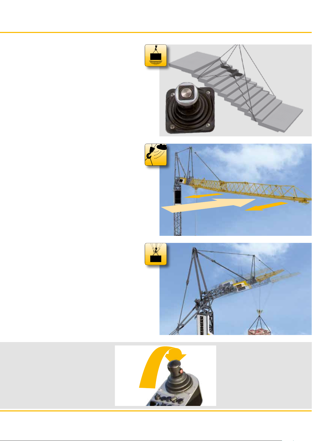
Flexible is efficient.
The success
on your site
The operational area of the 81 K encompasses apartment
block construction to industrial projects. Great flexibility with
11 different crane heights, the 30° raised jib angle and the
45°-obstruction avoidance angle equips the 81 K for every building site. Operations under power lines or in halls are
possible through the telescopic tower. Define the success of
your construction site yourself!
Short projection
You can use the full radius
also with limited building
site space.
57‘-1“ 85‘-3“ standard hook hight up to 132‘-5“
Fast climbing
Up to 6 inserted tower
sections enable 11 hook
heights.
8
Page 9
30
Range with lifting capacity
Adjustable jib in 4 lengths to meet individual requirements
– between 101 ft and 147 ft. You profit from customised
lifting curves.
Obstructions or high reaches
With the 30° raised jib position and the 45° jib obstruction
avoidance position you can match the crane to every operation – and reach hook heights of up to 180 ft.
147‘-1“ / 3,090 lbs
137‘-8“ / 3,640 lbs
121‘-4“ / 4,740 lbs
101‘-7“ / 6,390 lbs
30°
Variable slewing radius
Save more than 35% space requirements through reduced
slewing radius. The crane can be set up nearer buildings or
during operations with limited building site space. Choose
between reduced space requirements or less ballast.
Extreme situations
Also work with obstructions i.e. under power li-
nes with retracted tower.
45°
11‘-48“ - 9‘-0“
Multi-volt
100
200
Adjustment of operating
voltage to local condi-
0
tions (380 - 500 v / 5060 Hz).
9
Page 10
Our drive to your success.
Powerful drives manufactured in-house ensuring the highest quality – for decades
PLC-control for increased safety and user comfort
Steel construction resistant to torsion for durability and precise working
Comfortable cabin with optimum view for maximum working comfort
10
Page 11

11
Page 12

Unrivalled drives.
Strong and sensitive
The strong and precise hoist gear is central requirement
for increased handling capacity and safe working. It is
specially manufactured and assembled in-house for this
construction crane. For the first time ever in a fast-erecting crane in its class, the hoist gear can lift and lower
all loads absolutely steplessly. The wide rpm enables 2
rope operation at full speed. The intelligent ventilation
system cools the drive to optimum operation temperatures – independent from hoist rpm.
12
Power connection
Energy supply through easy access
connection at the undercarriage.
Page 13

Like the big ones
Due the stepless speeds of all to FC drives the driving performance corresponds to the top slewer and guarantees maximum handling capacity.
Slewing just as you want
Choose between absolutely sensitive slewing with low rpm
and high torque and high handling capacity with high rpm and
low torque. The ratio is freely adjustable.
Safe Control
The modern and safety orientated PLC control includes operating-range limiting system ABB, the interface to the anticollision system AKS or machine data recording MDE. The
graphic display offers a simple menu guide and shows all important operational data in one view. LiDAT offers additional
possibilities for remote diagnosis and data evaluation.
Simple scaling
With one weight the crane is scaled in
mi nutes. This saves time and money!
13
Page 14

Exceptionally equipped.
New design for efficient operation
In addition to the technical innovations the 81K was completely
redesigned. Optimum arrangement of controls in the new cabin
enables efficient and exhaustion free work. The optimised field of
vision maximises the view of building site. Tinted glass reduces
heat and protects against glare.
14
Large tool
compartment
and extra space for
radio control with
220 v socket for recharger.
New radio remote
control
with feedback. All the
important information
is shown on the display.
Page 15

Clear information
With the electronic monitoring system (EMS) the crane driver
has all the important parameters in one view. The display gives extensive information on loads, driving modes and many
other operational functions.
Safe guying
The jib is mounted with rods. Above all, increased safety and
low maintenance are aimed for in assembly.
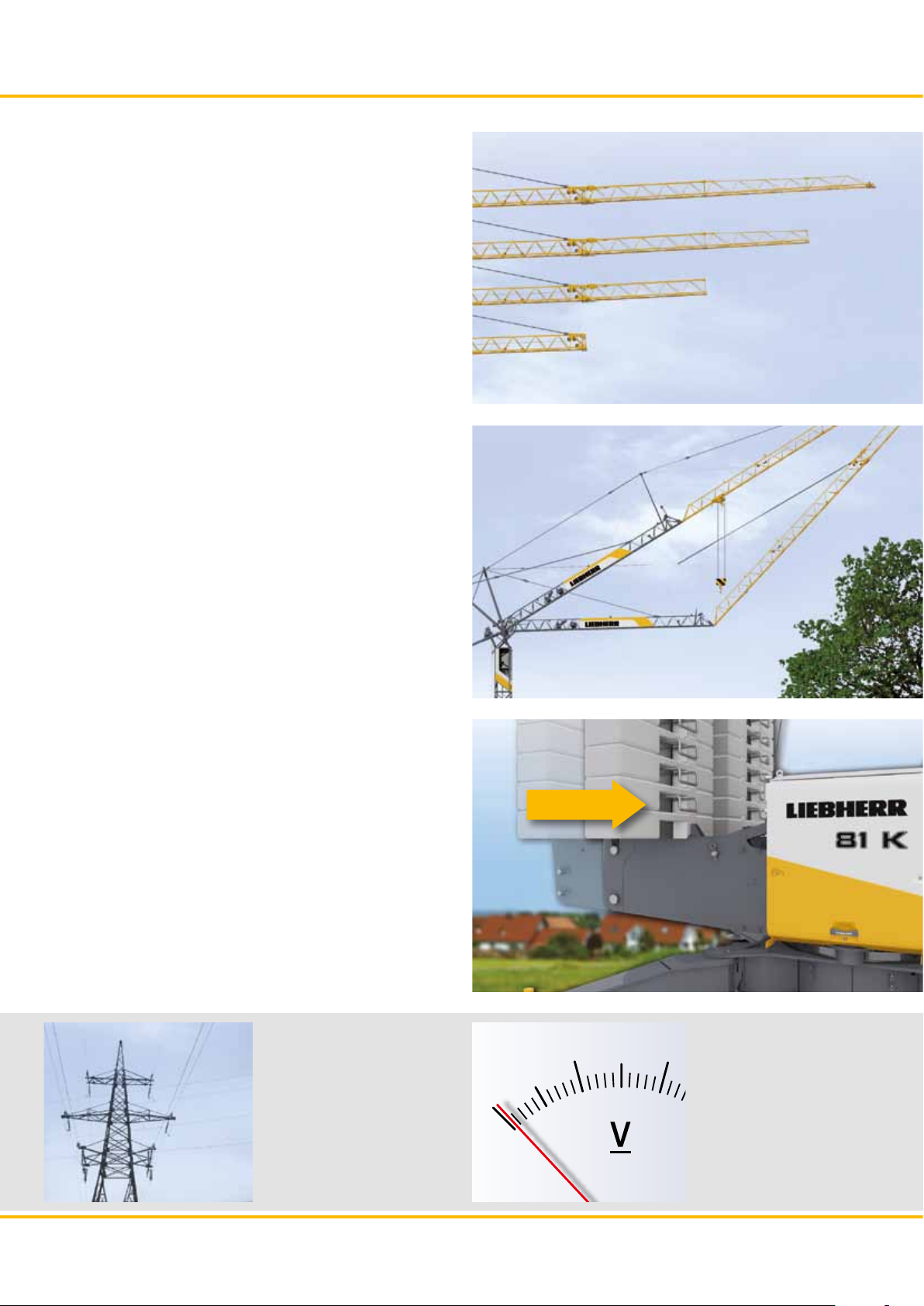
Play-free tower connection
After the tower is extended, it is tensed at 3 defined points
with the automatic tower locking device. Through the clearance free tower connection the whole steel structure is torsion
resistant and stable. Equipped as standard, the intermediate
hook heights can now be used quickly and easily.
Centrally
positioned jib
distributes the forces equally and carefully through the
tower.
Increased control stand height
for a better view.
15
Page 16

16
Page 17

Arrive efficiently.
Compact and flexible when transporting
Modular axle system – use your existing fleet
Maximum speed – up to 80 km/h to destination
Foldable A frame enables increased slope angle
17
Page 18

Arrive efficiently.
Sleak dimensions
Despite the unique standard hook height of the 81 K is compact
and flexible to transport. Moved as complete, ready assembly
unit. Fast into operation.
13‘-0“
18
52‘-0“
8‘-5“
Maximum speed
At up to 50 mp/h
you get your crane
to its destination.
50
Page 19

You have the choice
The modular high-speed and slow-speed axle system or se-
mitrailer offers the best transport possibility for every operational area. Existing axles can also be used.
Increased slope angle
With the foldable A frame, the 81 K reaches an angle of 15° –
that means: approx. 4.5 ft ground clearance.
Good to manoeuvre
With its steering angle of 180°, the steering axle guarantees
best manoeuvrability.
Twin tyres
If the road doesn’t
go all the way to
the building site,
twin tyres prevent
sinking.
15°
180°
Tower sections
Easily transported on
a lorry with an ideal
packing size of 7‘-9“
x 3‘-6“.
19
Page 20

20
34‘-8“ - 82‘-0“
Save money
– without hydraulics!
Page 21

Simply well set-up.
Adaptable assembly kinematics – without hydraulics
Different erecting curves for every situation
Fast ballasting with the semi-automatic ballasting device
Comfortable insertion of up to 6 tower sections
21
Page 22

Simply well set-up.
Get ready for work
Proceeds through thought out installation kinematics with rope. Assembly
is also possible at extremely low temperatures. The narrow air assembly
requires little installation space and and can be carried out with obstructions
of up to 82 ft.
82‘-0“
Choose the right erecting curve depending
on your operation
22
Screw jacks
Thanks to the trapeze thread,
the erected crane can be levelled and readjusted with little
effort.
Page 23

The better ballasting
The interplay of hoist and assembly winches enables fast and
comfortable mounting of the counterweight. With the assembly
winch, the tower moves up to 5 metres when unloading the
counterweight. Ballast plates are quickly mounted with the
hoist winch.
CC-Ballast
Bolted ballast plates reduce the time for mounting of counterweights by up to 50%. Only 8 hoists are required. Save time
and money!
Fast climbing
Up to 6 tower sections can be inserted comfortably and without
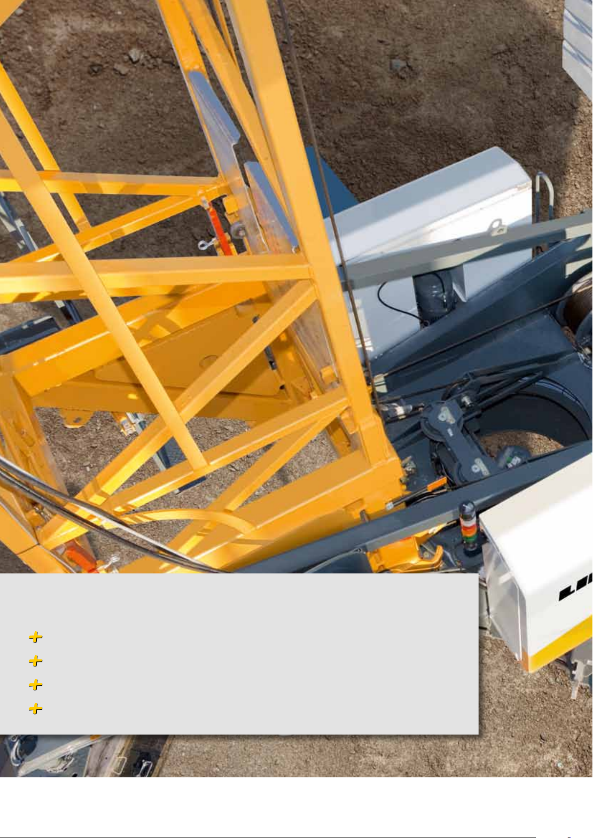
ground contact.
Quick-Connection
Simple interlocking between tower
and slewing platform with only one
hammer blow.
One-Man-Assembly
Patented, semi-automatic ballasting tongs and the ballast
centring enable one-man assembly.
23
Page 24

24
Page 25

Assured long life – maintenance and more.
Remote diagnosis with LiDAT
Replacement parts available quickly and long-term
Service network of authorized Liebherr dealers
Skilled personnel
25
Page 26

Assured long life – maintenance and more.
All information at a glance: always and everywhere
LiDAT is a data transmission and positioning system for Liebherr machines
and the machines of other manufacturers. Based on stateof- the-art data
transmission technology, LiDAT provides information on the location and operation of your machines, enabling their efficient management, optimal operation
scheduling and remote supervision.
26
Worldwide
service network
Liebherr is represented worldwide.
You can profit
from this network.
Delivery
A large network of
notable forwarding
agencies guarantee
fast and secure transportation.
Page 27

Original spare parts
Our spare parts are optimally tailored to every Liebherr crane.
The quality and functionality is of the highest standard across
the range. For a long life and high operational readiness of
your machines.
Smooth operation
With the central lubricating system the slewing ring is automatically lubricated. Care is never forgotten.
Liebherr construction cranes.
The development of the first quickly transportable and simple assembly crane over sixty years ago characterises the start of
Liebherr’s company history. The Liebherr construction crane programme is multifaceted like no other. It encompasses machines of all systems and sizes and offers the right lifting technology for high rise building. The flexible fast-erecting cranes and
powerful top-slewing models prove themselves in residential construction, industrial or large projects throughout the world.
Liebherr is an owner-managed company with long-term organisation. You can profit from this continuity.
27
Page 28

K
81
Turmdrehkran / Grue à tour / Gru a torre / Grúa torre
Guindaste de torre / Башенный поворотный кран
Tower Crane
lbs
lbs
lbs
K
81
K
81
K
81
K
81
44,090 lbs
r = 11’-5”
r = 9’-0”
77,160 lbs
88,190 lbs
30°
45°
123’
203’-4”
196’-5”
116’-1”
185’-0”
104’-7”
171’-6”
91’-2”
147’-6”
6’-6”
52’-8”
9’-8”6’-2”
0
1
3
0
1
2
3
4
5
62127’-6”
119’-7”
111’-9”
104’-0”
96’-1”
88’-3”
80’-4”
75’-8”
67’-9”
60’-0”
52’-2”
ca. 49,710 lbs
8’-5”
13’-0”
52’-0”
0’-82”
18’-2” (19’-9”)
24’-9” (26’-6”)
7’-5”
10’-5”
55’-0”
8’-5”
13’-0”
52’-0”
0’-8”
53’-0” – 55’-0”
6’-2”
7’-1” – 9’-1”
24’-4”
16’-2”
ca. 55,560 lbs
8’-5”
13’-1”
0’-8”
52’-0”
28’-2”
16’-2”
ca. 51,590 lbs
4’-1”
lbs
lbs
lbs
lbs
44,090 lbs
123’
203’-4”
196’-5”
116’-1”
185’-0”
147’-6”
6’-6”
ca. 49,710 lbs
8’-5”
13’-0”
10’-5”
8’-5”
13’-0”
6’-2”
7’-1” – 9’-1”
ca. 55,560 lbs
8’-5”
13’-1”
ca. 51,590 lbs
4’-1”
Technical data.
167’-3”
104’-0”
30°
45°
157’-4”
86’-9”
6,390 lbs
4,740 lbs
118’-1”
3,640 lbs
175’-5”
126’-6”
3,090 lbs
4 180’-4”
180’-4”
3 172’-6”
2 164’-7”
1 156’-8”
0 148’-9”
6
5
4
3
2
1
0
3
101’-7”
121’-4”
6,390 lbs
137’-8”
4,740 lbs
147’-6”
3,640 lbs
3,090 lbs
6 132’-5”
5 124’-7”
4 116’-8”
3 108’-9”
2 101’-0”
1 93’-2”
0 85’-3”
3 80’-7”
2 72’-8”
1 65’-0”
0
*
57’-1”
14’-8”x 14’-8”
Weight
* see instruction manual
28
81
K
2
1
0
r=3.50 m
r=2.75 m
14’-8”x 14’-8”
35000 kg
40000 kg
EN 14439:2009 –C25
20000 kg
Page 29

203’-4”
Ausladung und Tragfähigkeit / Portée et charge / Sbraccio e portata
Alcances y cargas / Alcance e capacidade de carga / Вылет и грузоподъемность
Radius and capacity
123’
196’-5”
116’-1”
185’-0”
104’-7”
171’-6”
30°
45°
9’-8”6’-2”
91’-2”
6’-6”
147’-6”
max. 149’-3”
min. 68’-9”
11’-5”
9’-0”
81
K
14’-8”x 14’-8”
52’-8”
62127’-6”
5
119’-7”
4
111’-9”
104’-0”
3
96’-1”
2
1
88’-3”
0
80’-4”
75’-8”
3
67’-9”
1
60’-0”
52’-2”
0
52’-0”
0’-82”
18’-2” (19’-9”)
24’-9” (26’-6”)
55’-0”
52’-0”
0’-8”
16’-2”
24’-4”
53’-0” – 55’-0”
0’-8”
16’-2”
28’-2”
52’-0”
81
K
7’-5”
10’-5”
81
K
6’-2”
7’-1” – 9’-1”
81
K
4’-1”
13’-0”
8’-5”
13’-0”
8’-5”
13’-1”
8’-5”
lbs
ca. 49,710 lbs
lbs
ca. 55,560 lbs
lbs
ca. 51,590 lbs
Radius and capacity
ft/lbs
ft
99’-2”
92’-6”
81’-6”
68’-3”
ft/lbs
9’-8” – 43’-6”
13,230
9’-8”
– 46’-3”
13,230
9’-8”
– 49’-5”
13,230
9’-8”
– 53’-5”
13,230
42’-7”
13,230
13,230
13,230
13,230
49’-2”
59’-1”
68’-9”
78’-7”
6,680
7,140
7,850
8,580
88’-6”
5,820
6,220
6,860
7,500
11,510
12,280
13,230
13,230
9,330
9,970
10,870
11,840
7,800
8,360
9,150
9,970
95’-1”
5,340
5,710
6,330
6,900
101’-7”
4,920
5,290
5,840
6,390
108’-3”
4,560
4,850
5,420
114’-8”
4,230
4,560
5,070
121’-4”
3,970
4,260
4,740
128 ’-0”
3,700
3,990
134’-5”
3,480
3,750
137 ’-8”
3,370
3,640
144’-4”
3,180
147 ’-6”
3,090
29
Page 30

m
Technical data.
13,230
13,230
13,230
13,230
99’-2”
9’-8” – 43’-6”
13,230
9’-8”
13,230
– 46’-3”
9’-8”
13,230
– 49’-5”
9’-8”
13,230
– 53’-5”
92’-6”
81’-6”
68’-3”
42’-7”
ft/lbs
ft/lbs
ft
Ausladung und Tragfähigkeit / Portée et charge / Sbraccio e portata
Alcances y cargas / Alcance e capacidade de carga / Вылет и грузоподъемность
Radius and capacity
Driving units Antriebe / Mécanismes d’entraînement / Meccanismi / Mecanismos / Mecanismos / Приводы
11,510
12,280
13,230
13,230
49’-2”
9,330
9,970
10,870
11,840
59’-1”
7,800
8,360
9,150
9,970
68’-9”
6,680
7,140
7,850
8,580
78’-7”
5,820
6,220
6,860
7,500
88’-6”
5,340
5,710
6,330
6,900
95’-1”
4,920
5,290
5,840
6,390
101’-7”
4,560
4,850
5,420
108’-3”
4,230
4,560
5,070
114’-8”
3,970
4,260
4,740
121’-4”
3,700
3,990
128 ’-0”
3,480
3,750
134’-5”
3,370
3,640
137 ’-8”
3,180
144’-4”
3,090
147 ’-6”
6,610
6,610
6,610
6,610
147’-6”
9’-8” – 55’-1”
6,660
9’-8” – 58’-1”
6,660
9’-8” – 69’-6”
6,660
9’-8” – 69’-6”
6,660
137’-8”
121’-4”
101’-7”
39’-4”
ft/lbs
ft/lbs
ft
6,610
6,610
6,610
6,610
45’-9”
6,550
6,610
6,610
6,610
52’-5”
6,020
6,530
6,610
6,610
59’-1”
5,560
6,040
6,610
6,610
65’-6”
5,160
5,600
6,420
6,610
72’-2”
4,630
5,050
5,800
6,610
82’-0”
4,410
4,810
5,530
6,390
86’-9”
4,190
4,590
5,290
91’-9”
3,950
4,320
4,980
98’-4”
3,750
4,100
4,740
104’-0”
3,620
3,950
108’-3”
3,420
3,750
114’-8”
3,310
3,640
118’-1”
3,220
141’-4”
3,090
126’-6”
Elevated jib 30° Auslegersteilstellung 30° Braccio inclinato a 30°
Pluma inclinada 30° / Lança inclinada 30° / 30°Положение стрелы под углом
/ / Flèche inclinée 30° /
Erection procedure
1
Standard erecting curves from
1 to 6 tower sections
2
Elevated erecting curve (+ 14‘-8“)
using the example of 6 tower
sections
55
50
45
40
35
30
25
2
1
20
15
10
5
0
K
81
0m
-5-10 5
6
5
4
3
2
1
0
10
15 20 25 30 35 40 45
Driving units
0 0,8
0 197 ft/min
0 82 ft/min
0 – 45°, 110 sec.
tr./min
BGL
6.7 hp FU
4 hp FU
2x2hpFU
4 hp FU
C.0.08.0080
20.1 hp FU
WIW 210 MZ 404
13,230
11,020
8,820
6,610
4,410
2,210
0
400 V Hz kVA
33
stepless
Speed
Speed
1
66 98 131 164
50 21,0 FU285’4” 4.3 x 6.5 qf
lbs ft/min
13,230
1
880
197
230 262
0 39
0 230
30
Page 31

Uses in summary.
SPEED
Pure two-line operation
Always maximum performance at full
speed.
25% more lifting capacity
In comparison to series precursors.
25 %
CC-Ballast
Save assembly time through bolted ballast
plates and heavy ballast.
MICROMOVE
Millimetre precise positioning at the touch
of a button.
Wind load control
The control reacts automatically to the
counter torque on the jib.
Load swing damping
Automatic compensation of jib movements
for static load.
Simple scaling
With only one weight the crane is scaled
in a few minutes.
Low maintenance assembly kinematics
Reliable assembly with ropes even at low
temperatures.
Variable slewing radius
35% less space requirements through
decrease of the slewing platform.
LMB
Fast climbing
Up to 6 tower sections can be inserted. Hook
heights of up to 180 ft can be reached.
Electronic load moment limitation
Secure transport of load until end stop.
Display on switch cabinet
with simple menu guide.
Operating data recording / evaluation
Recording of all operating and performance data of the crane for
evaluation and optimum servicing and maintenance.
31
Page 32

Don’t hang on…
Go for it!
Printed in Germany DWS LBC 675-06.09-1enUS. This information is supplied without liability. Subject to technical modifications.
Liebherr Construction Equipment Co.
4100 Chestnut Avenue, Newport News, VA 23607
Phone: (757) 245-5251, E-mail: info.lce@liebherr.com
www.liebherr.com
 Loading...