

Page 1
Precision Cooling
For Business-Critical Continuity™
Liebert XDV
User Manual–50 & 60 Hz
™
Page 2
GENERAL SAFETY GUIDELINES
SAVE THESE INSTRUCTIONS
WARNING
!
Risk of electric shock. Can cause injury or death.
Disconnect local and remote power supplies before working within.
Before proceeding with installation of XD cooling unit’s, read all instructions, verify that all
the parts are included, and check the nameplate to be sure the XD cooling unit’s voltage
matches available utility power.
Follow all local codes.
WARNING
!
Risk of unit falling over when installed on top of cabinet. Can cause property damage, injury
or death.
The XDV is top-heavy. Use extreme caution and care when moving and installing this unit.
WARNING
!
Risk of explosive discharge. Can cause equipment damage, injury or death.
Closing service valves may isolate liquid refrigerant, causing high pressure and rupture of
piping. Do not close valves without follow recommended procedures for repair, maintenance
and replacement of components. Installing pressure relief valves in field piping that may
become isolated by service valves.
NOTE
This document must be used together with site specific documentation and documentation for
other parts of the system (heat rejection devices and cooling modules).
NOTE
Before any action that could cause a disturbance in the Liebert XD system’s cooling function is
begun, the facility manager MUST be informed. In addition, after the action is taken and the
work is finished, the facility manager MUST be informed.
Fluorinated Greenhouse Gas Requirements—European Union
Stationary air conditioning, refrigeration, heat pump equipments and stationary fire protection systems in the European Community market and operating with fluorinated greenhouse gases (f-gas),
such as R407C, R134a, R410A, must comply with the F-Gas Regulation: (EC) No. 842/2006 (F-gas).
The regulation prohibits, among other actions, venting fluorinated greenhouse gases to the atmosphere.
The F-Gas Regulation also requires operators to use use all measures that are technically feasible
and do not entail disproportionate cost to prevent leakage of these gases, to test for leakage regularly
and to recover f-gas during equipment service and maintenance and before disposing of equipment.
Refer to the full regulation for additional details.
Page 3

TABLE OF CONTENTS
GENERAL SAFETY GUIDELINES . . . . . . . . . . . . . . . . . . . . . . . . . . . . . . . . . . . INSIDE FRONT COVER
1.0 LIEBERT XDV COMPONENT LOCATIONS AND MODEL NUMBER NOMENCLATURE . . . . . . . . . 1
2.0 INSTALLATION . . . . . . . . . . . . . . . . . . . . . . . . . . . . . . . . . . . . . . . . . . . . . . . . . . . . . . . . . .2
2.1 References . . . . . . . . . . . . . . . . . . . . . . . . . . . . . . . . . . . . . . . . . . . . . . . . . . . . . . . . . . . . . . . . . . 2
2.2 Pre-Installation Checks . . . . . . . . . . . . . . . . . . . . . . . . . . . . . . . . . . . . . . . . . . . . . . . . . . . . . . . 2
2.3 Parts Included With Liebert XDV . . . . . . . . . . . . . . . . . . . . . . . . . . . . . . . . . . . . . . . . . . . . . . . 2
2.4 Installation Considerations . . . . . . . . . . . . . . . . . . . . . . . . . . . . . . . . . . . . . . . . . . . . . . . . . . . . 2
2.4.1 Room Preparation. . . . . . . . . . . . . . . . . . . . . . . . . . . . . . . . . . . . . . . . . . . . . . . . . . . . . . . . . . . . . 2
3.0 GENERAL PRODUCT INFORMATION . . . . . . . . . . . . . . . . . . . . . . . . . . . . . . . . . . . . . . . . . . .3
3.1 Product/System Description . . . . . . . . . . . . . . . . . . . . . . . . . . . . . . . . . . . . . . . . . . . . . . . . . . . 3
3.2 Checking and Unpacking . . . . . . . . . . . . . . . . . . . . . . . . . . . . . . . . . . . . . . . . . . . . . . . . . . . . . . 3
3.3 Equipment Inspection . . . . . . . . . . . . . . . . . . . . . . . . . . . . . . . . . . . . . . . . . . . . . . . . . . . . . . . . 4
3.3.1 Recyclable Packaging . . . . . . . . . . . . . . . . . . . . . . . . . . . . . . . . . . . . . . . . . . . . . . . . . . . . . . . . . . 4
3.3.2 Unit Handling. . . . . . . . . . . . . . . . . . . . . . . . . . . . . . . . . . . . . . . . . . . . . . . . . . . . . . . . . . . . . . . . 5
3.3.3 Unpacking the Unit . . . . . . . . . . . . . . . . . . . . . . . . . . . . . . . . . . . . . . . . . . . . . . . . . . . . . . . . . . . 5
4.0 MECHANICAL CONSIDERATIONS . . . . . . . . . . . . . . . . . . . . . . . . . . . . . . . . . . . . . . . . . . . . .8
4.1 Determining Placement in the Conditioned Space. . . . . . . . . . . . . . . . . . . . . . . . . . . . . . . . . . 8
4.2 Changing the Air Intake Location. . . . . . . . . . . . . . . . . . . . . . . . . . . . . . . . . . . . . . . . . . . . . . . 9
5.0 MOUNTING THE LIEBERT XDV . . . . . . . . . . . . . . . . . . . . . . . . . . . . . . . . . . . . . . . . . . . . .10
5.1 Mounting the Liebert XDV on Top of the Cabinet . . . . . . . . . . . . . . . . . . . . . . . . . . . . . . . . . 10
5.1.1 Bolting Liebert XDV to Top of Cabinet . . . . . . . . . . . . . . . . . . . . . . . . . . . . . . . . . . . . . . . . . . . 10
5.1.2 Using Supplied Clips for Mounting . . . . . . . . . . . . . . . . . . . . . . . . . . . . . . . . . . . . . . . . . . . . . . 12
5.2 Suspended Mounting Method . . . . . . . . . . . . . . . . . . . . . . . . . . . . . . . . . . . . . . . . . . . . . . . . . 13
5.2.1 Suspending the Liebert XDV from Unistruts . . . . . . . . . . . . . . . . . . . . . . . . . . . . . . . . . . . . . . 14
5.2.2 Suspending the Liebert XDV from Overhead Structures . . . . . . . . . . . . . . . . . . . . . . . . . . . . 14
5.3 Mounting Liebert XDVs in Stacked Setup . . . . . . . . . . . . . . . . . . . . . . . . . . . . . . . . . . . . . . . 16
5.3.1 Hanging Stacked Liebert XDVs from Unistruts . . . . . . . . . . . . . . . . . . . . . . . . . . . . . . . . . . . . 17
5.3.2 Hanging Stacked Liebert XDVs from the Overhead Structure . . . . . . . . . . . . . . . . . . . . . . . . 18
6.0 PIPING . . . . . . . . . . . . . . . . . . . . . . . . . . . . . . . . . . . . . . . . . . . . . . . . . . . . . . . . . . . . . . .19
6.1 European Union Fluorinated Greenhouse Gas Requirements . . . . . . . . . . . . . . . . . . . . . . . 19
6.2 System Connection Configuration. . . . . . . . . . . . . . . . . . . . . . . . . . . . . . . . . . . . . . . . . . . . . . 19
6.2.1 Piping Connections to Liebert XDP or Liebert XDC . . . . . . . . . . . . . . . . . . . . . . . . . . . . . . . . 20
6.3 Connection Methods and Points . . . . . . . . . . . . . . . . . . . . . . . . . . . . . . . . . . . . . . . . . . . . . . . 20
6.4 Hard Piped Connection Sizes. . . . . . . . . . . . . . . . . . . . . . . . . . . . . . . . . . . . . . . . . . . . . . . . . . 22
6.4.1 Holding Charge—Hard-Piped Units . . . . . . . . . . . . . . . . . . . . . . . . . . . . . . . . . . . . . . . . . . . . . 22
6.4.2 Brazing Preparations—Hard-Piped Units . . . . . . . . . . . . . . . . . . . . . . . . . . . . . . . . . . . . . . . . 23
6.5 Recommended Piping Size . . . . . . . . . . . . . . . . . . . . . . . . . . . . . . . . . . . . . . . . . . . . . . . . . . . . 23
6.6 Connection Methods—One-Shot Connections . . . . . . . . . . . . . . . . . . . . . . . . . . . . . . . . . . . . 24
6.6.1 Refrigerant Charge—Pre-Charged Option . . . . . . . . . . . . . . . . . . . . . . . . . . . . . . . . . . . . . . . . 25
6.7 Field Installation of Liebert Flex Pipe Kit on Liebert XDV. . . . . . . . . . . . . . . . . . . . . . . . . . 25
i
Page 4

6.8 Connecting Liebert XD Flex Pipe to Liebert XDV Modules. . . . . . . . . . . . . . . . . . . . . . . . . . 25
6.9 Connecting a Liebert XDV with Liebert Flex Pipe to an Operational
Liebert XD System . . . . . . . . . . . . . . . . . . . . . . . . . . . . . . . . . . . . . . . . . . . . . . . . . . . . . . . . . . 26
6.10 Disconnecting a Liebert XDV With Liebert Flex Pipe From a Liebert XD System . . . . . . . 28
6.11 Insulation . . . . . . . . . . . . . . . . . . . . . . . . . . . . . . . . . . . . . . . . . . . . . . . . . . . . . . . . . . . . . . . . . 29
7.0 ELECTRICAL . . . . . . . . . . . . . . . . . . . . . . . . . . . . . . . . . . . . . . . . . . . . . . . . . . . . . . . . . . . 30
7.1 Connecting High Voltage Cables for CSA/C-US Certified Units . . . . . . . . . . . . . . . . . . . . . . 30
7.2 Connecting Low Voltage Wiring—Optional . . . . . . . . . . . . . . . . . . . . . . . . . . . . . . . . . . . . . . 32
8.0 INSTALLATION CHECKLIST AND SYSTEM FILL FOR STARTUP . . . . . . . . . . . . . . . . . . . . . . .33
8.1 Checklist for Proper Installation . . . . . . . . . . . . . . . . . . . . . . . . . . . . . . . . . . . . . . . . . . . . . . . 33
8.2 Charging with Refrigerant and Starting the Liebert XD System . . . . . . . . . . . . . . . . . . . . . 33
9.0 OPERATION . . . . . . . . . . . . . . . . . . . . . . . . . . . . . . . . . . . . . . . . . . . . . . . . . . . . . . . . . . .34
9.1 Start the Liebert XDV . . . . . . . . . . . . . . . . . . . . . . . . . . . . . . . . . . . . . . . . . . . . . . . . . . . . . . . 34
10.0 MAINTENANCE . . . . . . . . . . . . . . . . . . . . . . . . . . . . . . . . . . . . . . . . . . . . . . . . . . . . . . . . .35
10.1 Fluorinated Greenhouse Gas Requirements. . . . . . . . . . . . . . . . . . . . . . . . . . . . . . . . . . . . . . 35
10.2 Internal Access . . . . . . . . . . . . . . . . . . . . . . . . . . . . . . . . . . . . . . . . . . . . . . . . . . . . . . . . . . . . . 35
10.2.1 Accessing Internal Electrical Components . . . . . . . . . . . . . . . . . . . . . . . . . . . . . . . . . . . . . . . . 36
11.0 SPECIFICATIONS . . . . . . . . . . . . . . . . . . . . . . . . . . . . . . . . . . . . . . . . . . . . . . . . . . . . . . . .38
ii
Page 5

FIGURES
Figure 1 Liebert XDV component locations . . . . . . . . . . . . . . . . . . . . . . . . . . . . . . . . . . . . . . . . . . . . . . . . . . . 1
Figure 2 Liebert XDV model number nomenclature . . . . . . . . . . . . . . . . . . . . . . . . . . . . . . . . . . . . . . . . . . . . 1
Figure 3 Liebert XDV hydraulic diagram. . . . . . . . . . . . . . . . . . . . . . . . . . . . . . . . . . . . . . . . . . . . . . . . . . . . . 3
Figure 4 Recommended unit handling equipment . . . . . . . . . . . . . . . . . . . . . . . . . . . . . . . . . . . . . . . . . . . . . . 4
Figure 5 Removing domestic shipping package . . . . . . . . . . . . . . . . . . . . . . . . . . . . . . . . . . . . . . . . . . . . . . . . 5
Figure 6 Removing export shipping package . . . . . . . . . . . . . . . . . . . . . . . . . . . . . . . . . . . . . . . . . . . . . . . . . . 6
Figure 7 Removing Liebert XDV from shipping pallet . . . . . . . . . . . . . . . . . . . . . . . . . . . . . . . . . . . . . . . . . . 7
Figure 8 Liebert XDV dimensions. . . . . . . . . . . . . . . . . . . . . . . . . . . . . . . . . . . . . . . . . . . . . . . . . . . . . . . . . . . 8
Figure 9 Changing the Liebert XDV’s air intake location . . . . . . . . . . . . . . . . . . . . . . . . . . . . . . . . . . . . . . . . 9
Figure 10 Positioning the Liebert XDV . . . . . . . . . . . . . . . . . . . . . . . . . . . . . . . . . . . . . . . . . . . . . . . . . . . . . . 10
Figure 11 Mounting hole locations—standard mounting method. . . . . . . . . . . . . . . . . . . . . . . . . . . . . . . . . . 11
Figure 12 Mounting hole locations—alternate mounting points . . . . . . . . . . . . . . . . . . . . . . . . . . . . . . . . . . 11
Figure 13 Mounting clip placement . . . . . . . . . . . . . . . . . . . . . . . . . . . . . . . . . . . . . . . . . . . . . . . . . . . . . . . . . 12
Figure 14 Dimensions—optional external hanging brackets . . . . . . . . . . . . . . . . . . . . . . . . . . . . . . . . . . . . . 13
Figure 15 Suspending Liebert XDV from Unistruts . . . . . . . . . . . . . . . . . . . . . . . . . . . . . . . . . . . . . . . . . . . . 14
Figure 16 Suspending Liebert XDV from the overhead structure . . . . . . . . . . . . . . . . . . . . . . . . . . . . . . . . . 15
Figure 17 Stacking configuration offset . . . . . . . . . . . . . . . . . . . . . . . . . . . . . . . . . . . . . . . . . . . . . . . . . . . . . . 16
Figure 18 Attach hanger brackets to Liebert XDV for stacked arrangement . . . . . . . . . . . . . . . . . . . . . . . . 17
Figure 19 Stacked Liebert XDVs suspended from Unistruts . . . . . . . . . . . . . . . . . . . . . . . . . . . . . . . . . . . . . 17
Figure 20 Stacked Liebert XDVs ready for suspension from overhead structure . . . . . . . . . . . . . . . . . . . . . 18
Figure 21 Typical Liebert XDV piping—interlaced connections . . . . . . . . . . . . . . . . . . . . . . . . . . . . . . . . . . . 19
Figure 22 Typical Liebert XDV piping—non-interlaced connection . . . . . . . . . . . . . . . . . . . . . . . . . . . . . . . . 20
Figure 23 Hard-piped connection diagram . . . . . . . . . . . . . . . . . . . . . . . . . . . . . . . . . . . . . . . . . . . . . . . . . . . . 21
Figure 24 Piping location and connection sizes—hard-piped units . . . . . . . . . . . . . . . . . . . . . . . . . . . . . . . . 22
Figure 25 Schrader valve location for venting holding charge . . . . . . . . . . . . . . . . . . . . . . . . . . . . . . . . . . . . 23
Figure 26 Piping location and connection sizes—pre-charged units with one-shot connections. . . . . . . . . . 24
Figure 27 Liebert XD Flex Pipe dimensions—straight and 90-degree connections. . . . . . . . . . . . . . . . . . . . 25
Figure 28 Liebert XD prefabricated piping assembly . . . . . . . . . . . . . . . . . . . . . . . . . . . . . . . . . . . . . . . . . . . 26
Figure 29 Detail view of Liebert XD Flex Pipe and prefabricated piping port. . . . . . . . . . . . . . . . . . . . . . . . 27
Figure 30 Liebert XD system with prefabricated piping assembly and Liebert XD Flex Pipe . . . . . . . . . . . 27
Figure 31 Profile view of the Liebert XD system with one-shot connections . . . . . . . . . . . . . . . . . . . . . . . . . 28
Figure 32 Piping mains without Liebert XDV and Liebert Flex Pipe. . . . . . . . . . . . . . . . . . . . . . . . . . . . . . . 29
Figure 33 Liebert XDV electrical connections for CSA-approved units . . . . . . . . . . . . . . . . . . . . . . . . . . . . . 30
Figure 34 Liebert XDV electrical connections for CE-approved units . . . . . . . . . . . . . . . . . . . . . . . . . . . . . . 31
Figure 35 Low voltage connections . . . . . . . . . . . . . . . . . . . . . . . . . . . . . . . . . . . . . . . . . . . . . . . . . . . . . . . . . . 32
Figure 36 Fan switches . . . . . . . . . . . . . . . . . . . . . . . . . . . . . . . . . . . . . . . . . . . . . . . . . . . . . . . . . . . . . . . . . . . 34
Figure 37 Accessing internal electrical components . . . . . . . . . . . . . . . . . . . . . . . . . . . . . . . . . . . . . . . . . . . . 36
Figure 38 Removing the fan tray . . . . . . . . . . . . . . . . . . . . . . . . . . . . . . . . . . . . . . . . . . . . . . . . . . . . . . . . . . . 37
TABLES
Table 1 Application limits . . . . . . . . . . . . . . . . . . . . . . . . . . . . . . . . . . . . . . . . . . . . . . . . . . . . . . . . . . . . . . . . 2
Table 2 Dimensional data . . . . . . . . . . . . . . . . . . . . . . . . . . . . . . . . . . . . . . . . . . . . . . . . . . . . . . . . . . . . . . . . 8
Table 3 Suspension hardware and bracket dimensional data . . . . . . . . . . . . . . . . . . . . . . . . . . . . . . . . . . . 13
Table 4 Branch piping sizes for refrigerant loop . . . . . . . . . . . . . . . . . . . . . . . . . . . . . . . . . . . . . . . . . . . . . 24
Table 5 Liebert XDV10 specifications . . . . . . . . . . . . . . . . . . . . . . . . . . . . . . . . . . . . . . . . . . . . . . . . . . . . . . 38
Table 6 Liebert XDV8 specifications . . . . . . . . . . . . . . . . . . . . . . . . . . . . . . . . . . . . . . . . . . . . . . . . . . . . . . . 39
Table 7 Liebert XD Liebert Flex Pipe assemblies, supply and return . . . . . . . . . . . . . . . . . . . . . . . . . . . . 40
iii
Page 6

iv
Page 7
Liebert XDV Component Locations and Model Number Nomenclature
1.0 LIEBERT XDV COMPONENT LOCATIONS AND MODEL NUMBER NOMENCLATURE
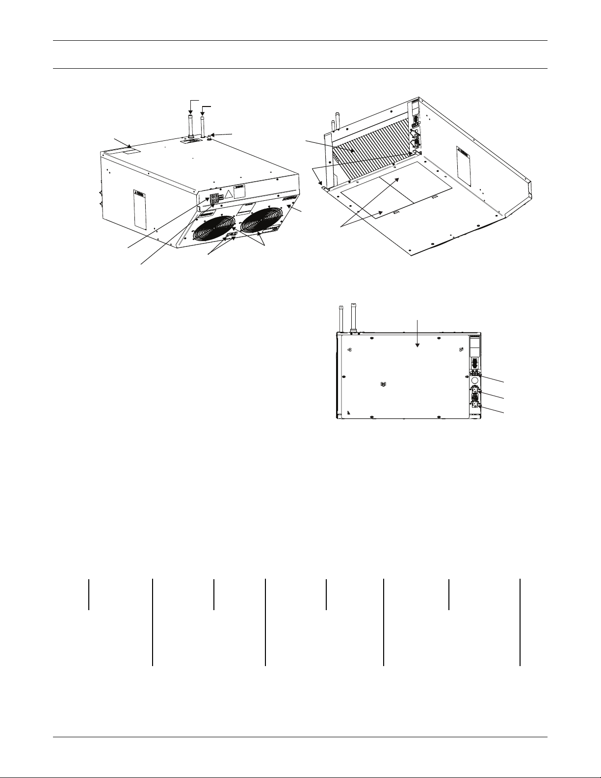
Figure 1 Liebert XDV component locations
2
3
Rear of Liebert XDV
13
Top of Liebert XDV
9
11
15
4
Front of Liebert XDV
16
14
XDV Components and Nomenclature
1. Removable Fan Tray
2. Return Line
3. Supply Line
4. Fan Switches
5. Removable Blocker Plates
6. Removable Rear Inlet Grille
7. Mounting Clips for Cabinets
8. Primary Power Inlet (CE-approved units have
non-detachable power cord)
9. Primary Circuit Breaker
10. Secondary Power Inlet (CE-approved units have
non-detachable power cord)
11. Secondary Circuit Breaker
12. Connections for Condensate Detection Option
13. Serial Tag
14. Heat Exchanger
15. Schrader Valve
16. Fans
7
1
5
Bottom View of Liebert XDV
6
12
10
8
Rear of Liebert XDV
Figure 2 Liebert XDV model number nomenclature
Example: XDV10BK– –*
XD V B K —
Liebert X-treme
heat density
system
Vertical top
cooler
10
Model
size
K = 120V-1ph-60Hz
T=208-240V-1ph-60Hz,
B = Base unit
D = Unit with
condensate
detection
S= 230V, 1ph-50Hz
220-240-1ph-50Hz
— = Hard Piped
P = Pre-charged (one-shot) Coupling)
R = Removable Coupling
1
—
— = Domestic
Packaging
E = Export
Packaging
*
Revision
level
Page 8
2.0 INSTALLATION
2.1 References
This document must be used together with site specific documentation and documentation for other
parts of the system.
2.2 Pre-Installation Checks
• Verify that the Liebert XDV voltage matches the available utility power. The serial tag with this
information is on the top of the unit, near the rear.
• Check the received materials to be sure all required assemblies and parts have been received. If
you discover any external damage, report it to the shipping company and your local Liebert representative.
2.3 Parts Included With Liebert XDV
• Installation manual (this document)
• Liebert XDV module
• Parts bag including
• IEC 10 ft. (3m) power cords, 2 (60Hz only; power cords for 50Hz are attached)
• 1/4 - 20 full thread 1" bolts, 4
• 1/4 inch locking hex nuts, 2
• mounting clips, 2
Installation
2.4 Installation Considerations
Each Liebert XDV module is to be securely mounted either on the top of a computer cabinet or rack or
above the heat-producing equipment. Mounting the Liebert XDV above the rack requires Liebert’s
optional mounting kit.
The units are designed to be mounted without modification on Liebert Foundation™ cabinets. Mounting clips included with the Liebert XDV permit installation on other manufacturers’ cabinets and
racks. The clips also can be used with the Foundation for stronger attachment.
Determine whether the Liebert XDV includes the condensate detection option (factory-installed). This
option will require separate low voltage connections to a monitoring unit.
To minimize the possibility of condensation, insulate all piping between the Liebert XDV and the Liebert XDP or Liebert XDC.
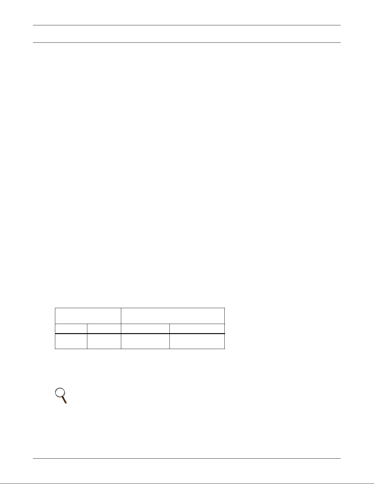
Table 1 Application limits
Input Voltage
Minimum Maximum Dry Bulb Temp. Relative Humidity
-10% +10%
2.4.1 Room Preparation
The room should be well insulated and must have a sealed vapor barrier. The vapor barrier in the
ceiling and walls can be a polyethylene film. Paint on concrete walls and floors should contain either
rubber or plastic.
NOTE
The vapor barrier is the single most important requirement for maintaining
environmental control in the conditioned space.
Outside or fresh air should be kept to a minimum when temperature and humidity must be tightly
controlled. Outside air adds to the cooling, heating, dehumidifying and humidifying loads of the site.
Doors should be properly sealed to minimize leaks and should not contain ventilation grilles.
60° to 100°F
(16° to 38°C)
Range of Return Air
Conditions to Unit
20% to 80%
2
Page 9
3.0 GENERAL PRODUCT INFORMATION
3.1 Product/System Description
The Liebert XDV cooling system is designed to be attached to the top of a computer cabinet or rack
containing heat dissipating equipment. Two fans draw hot air exhausted from the equipment or from
the hot aisle, pass it through a cooling coil and discharge cool air back down to the cold aisle, where
the equipment's air intake is located. The Liebert XDV comes from the factory ready to draw heated
air through a perforated grille on the back of the unit. The Liebert XDV is easily modified to draw hot
air through the bottom of the unit, should that cooling method be better suited to your application.
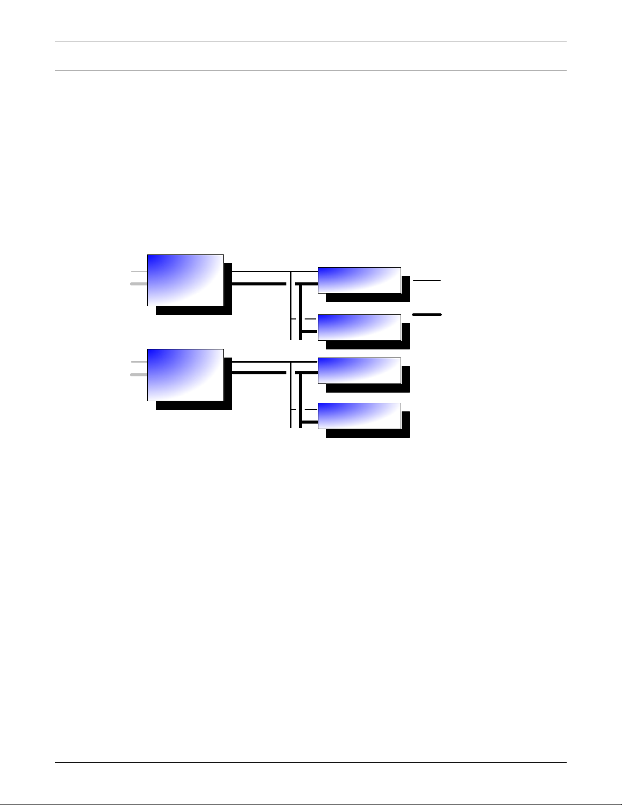
The complete system consists of Liebert XDV modules, Liebert XDP or Liebert XDC coolant distribution units, power and signal cabling and interconnecting piping, see Figure 3 below.
A condensate detection option gives notification if any condensation occurs in the Liebert XDV.
Figure 3 Liebert XDV hydraulic diagram
General product information
Liebert XDC
or
Liebert XD P
Liebert XDC
or
Liebert XD P
3.2 Checking and Unpacking
When the Liebert XDV is delivered, inspect all items for either visible or concealed damage. Damage
should be immediately reported to the carrier and a damage claim filed with a copy sent to Liebert or
to your sales representative. If you later find any concealed damage, report it to the shipping company
and your local Liebert representative.
Check to be sure all required assemblies and parts have been received.
The Liebert XDV is shipped in a protective carton and secured to a pallet (see Figures 5 and 6). Do
not remove these protective items from the Liebert XDV before it is at the installation location. When
unpacking and handling the Liebert XDV, exercise extra care to prevent damage.
Pumped
Refrigerant
Pumped
Refrigerant
Liebert XD
Cooling Module *
Liebert XD
Cooling Module *
Liebert XD
Cooling Module *
Liebert XD
Cooling Module *
Supply
Lines
Return
Lines
* Lieber t XDC F,
XDH , XDO or XDV
3
Page 10
3.3 Equipment Inspection
Upon arrival of the unit, and before unpacking, verify that the labeled equipment matches the bill of
lading. Carefully inspect all items for either visible or concealed damage. Damage should be immediately reported to the carrier and a damage claim filed with a copy sent to Liebert Corporation or to
your sales representative.
CAUTION
!
Risk of sudden refrigerant discharge. Can cause loss of charge and minor injury.
If the optional pre-charged option is chosen, the Liebert XDV unit is shipped with a full
charge of R-134a refrigerant under pressure. Do not remove the pipe caps or plugs before the
unit is ready for connection to Liebert XD Piping.
Supply and return fittings on the pre-charged Liebert XDV units are one-shot connections. Do
not disconnect one-shot connections after they have been connected. Disconnection will
release pressurized R-134a refrigerant from the Liebert XDV.
3.3.1 Recyclable Packaging
General product information
All material used to package this unit is recyclable. Please save for future use or
dispose of the material appropriately.
WARNING
!
Risk of improper handling. Can cause equipment damage, injury or death.
Read all of the following instructions before attempting to move, lift, remove packaging from,
or preparing unit for installation.
CAUTION
!
Risk of sharp edges, splinters and exposed fasteners can cause injury.
Only properly trained personnel wearing appropriate safety headgear, gloves, shoes and
glasses should attempt to move, lift, remove packaging from, or prepare unit for installation.
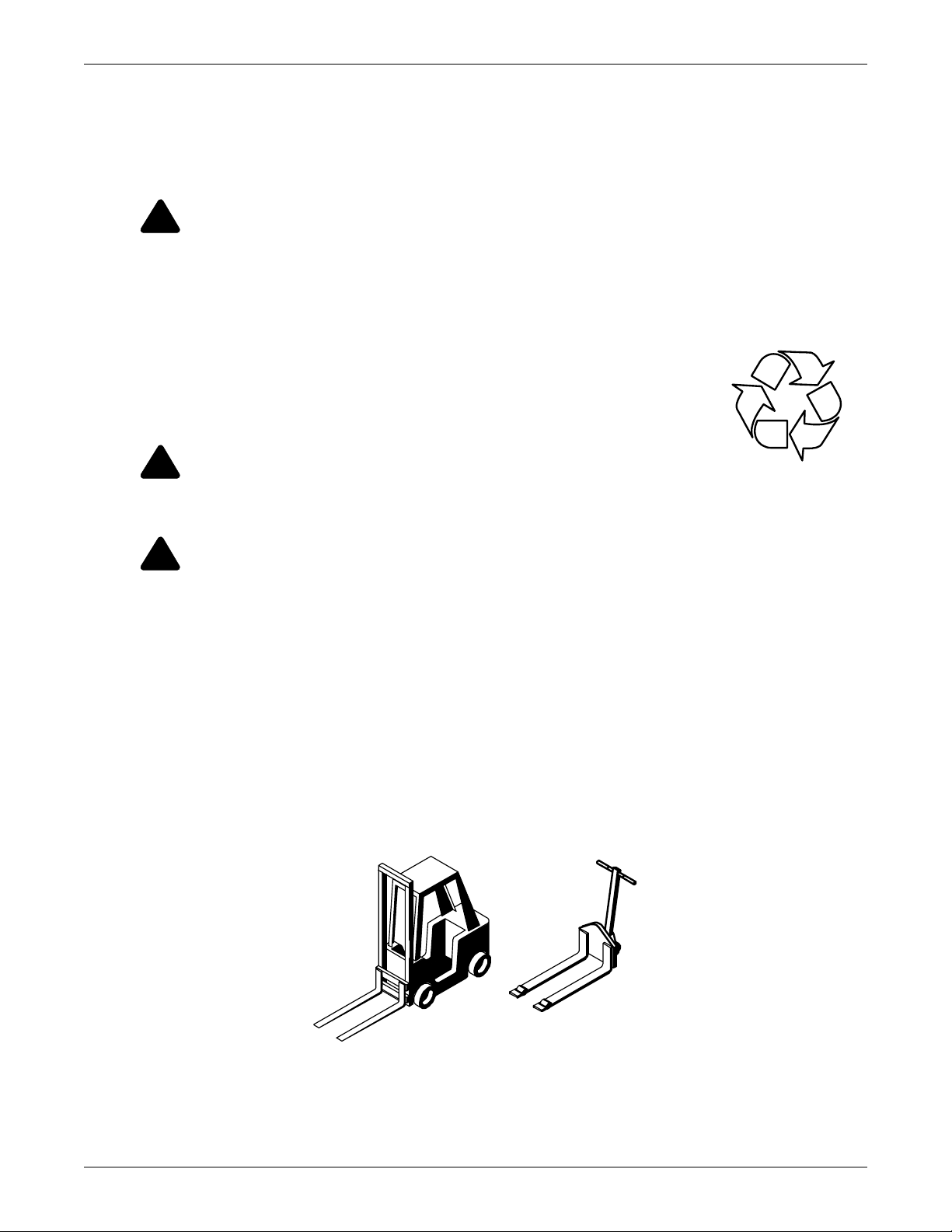
NOTICE
Risk of unit damage if improperly stored. Keep the unit indoors and protected from dampness,
freezing temperatures and contact damage.
NOTICE
Risk of damage from forklift. Improper handling with the forklift can cause exterior and/or
underside damage.
Keep tines of the forklift level and at a height suitable to fit below the skid.
Figure 4 Recommended unit handling equipment
R
Forklift
Pallet Jack
4
Page 11
3.3.2 Unit Handling
If possible, transport the unit using a forklift or pallet jack.
• If using a forklift or pallet jack, ensure that the fork tine length is suitable to safely move the
packaged unit.
• Liebert Corporation recommends that the unit remain in the protective packaging until located at
the installation site.
• When handling and unpacking the unit, exercise great care to prevent damage.
• Do not use unit piping to lift or move the Liebert XDV
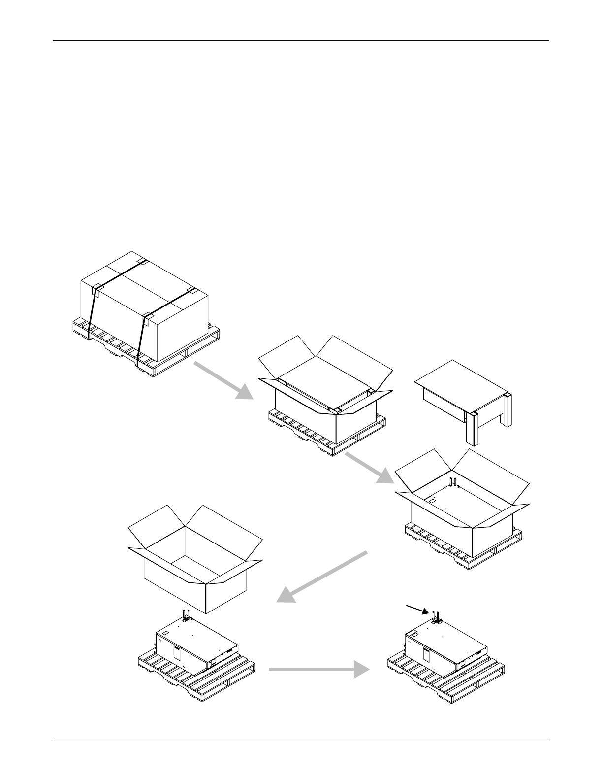
3.3.3 Unpacking the Unit
Domestic Packaging
1. Remove outer packaging when ready to install the Liebert XDV.
2. Keep the Liebert XDV covered by the unit bag until removal from pallet.
Figure 5 Removing domestic shipping package
General product information
Plastic bag used for shipping
not shown for clarity.
Step 1
Step 4
Step 2
Step 3
Do not use unit piping to lift or
move the Liebert XDV
Step 5
5
Page 12
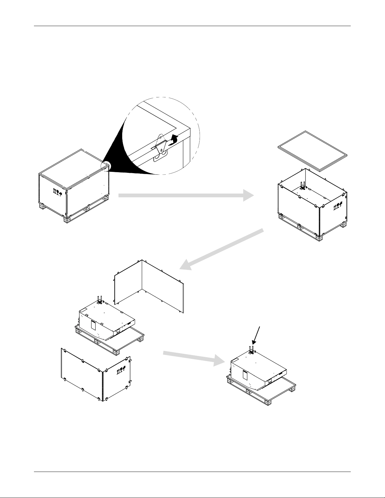
Export Packaging
1. Unbend all metal tabs as indicated in Step 1 in Figure 6.
2. Remove outer packaging when ready to install the Liebert XDV.
3. Keep the Liebert XDV covered by the unit bag until removal from pallet.
4. Do not use unit piping to lift or move the Liebert XDV.
Figure 6 Removing export shipping package
General product information
Plastic bag used for shipping
not shown for clarity.
Step 1
Step 3
Step 2
Do not use unit piping to lift
or move the Liebert XDV
Step 4
6
Page 13
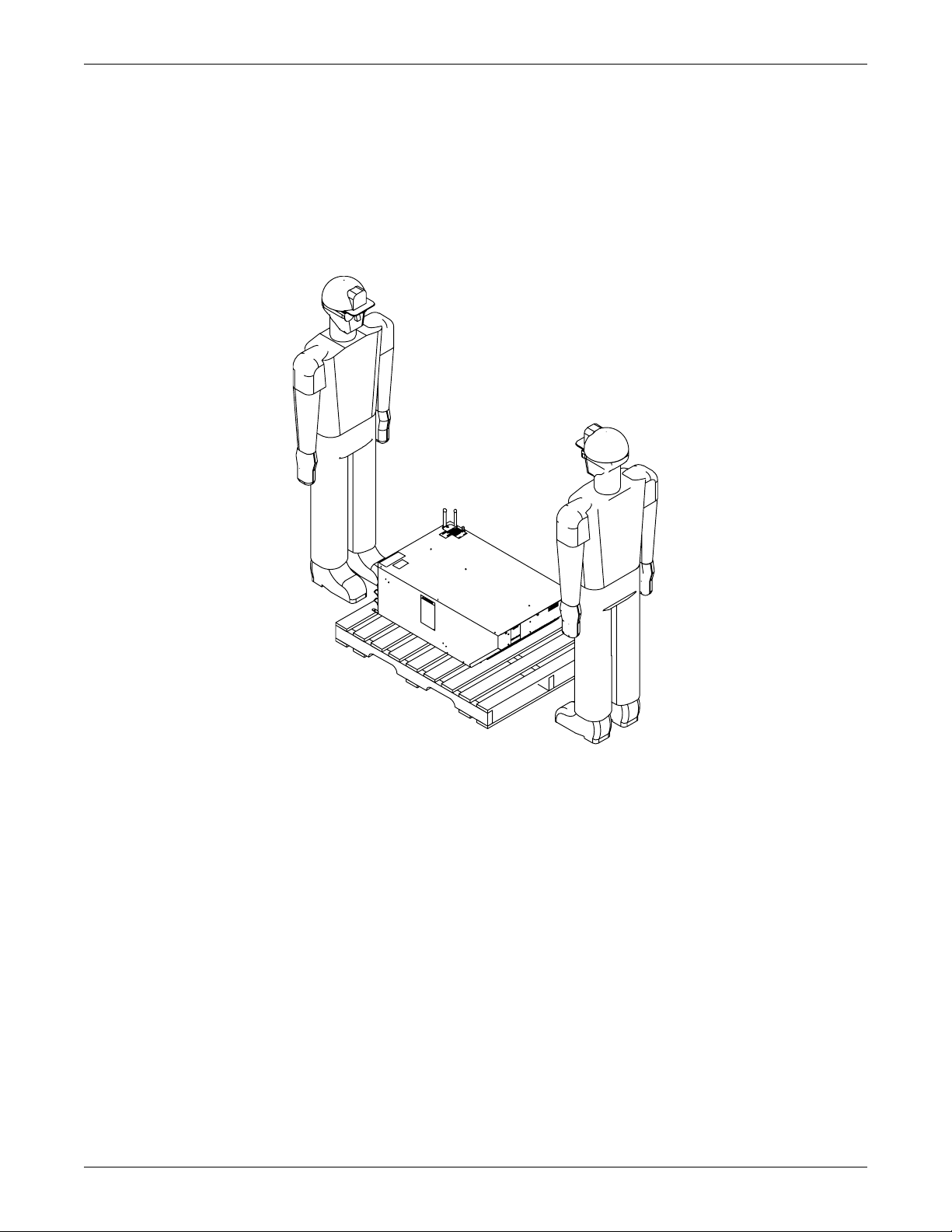
Removing the Liebert XDV from the Pallet
1. Unfold the unit bag to expose the Liebert XDV.
2. Verify the nameplate information found on the Liebert XDV against the bill of lading. If the
information does not match the product specified, contact your local Liebert sales representative.
3. At least two properly trained personnel may lift the Liebert XDV off the pallet and onto a flat
surface.
4. To protect the Liebert XDV’s paint, lay non-abrasive material, longer than the unit, on the flat
surface before moving the Liebert XDV.
Figure 7 Removing Liebert XDV from shipping pallet
General product information
Removing the Liebert XDV
from its shipping pallet
requires two people.
7
Page 14
4.0 MECHANICAL CONSIDERATIONS
4.1 Determining Placement in the Conditioned Space
Liebert XDVs should be placed above or on top of the cabinets that generate the greatest amount of
heat. If heat loads are dispersed evenly throughout the room, the Liebert XDV modules may be
spread out accordingly.
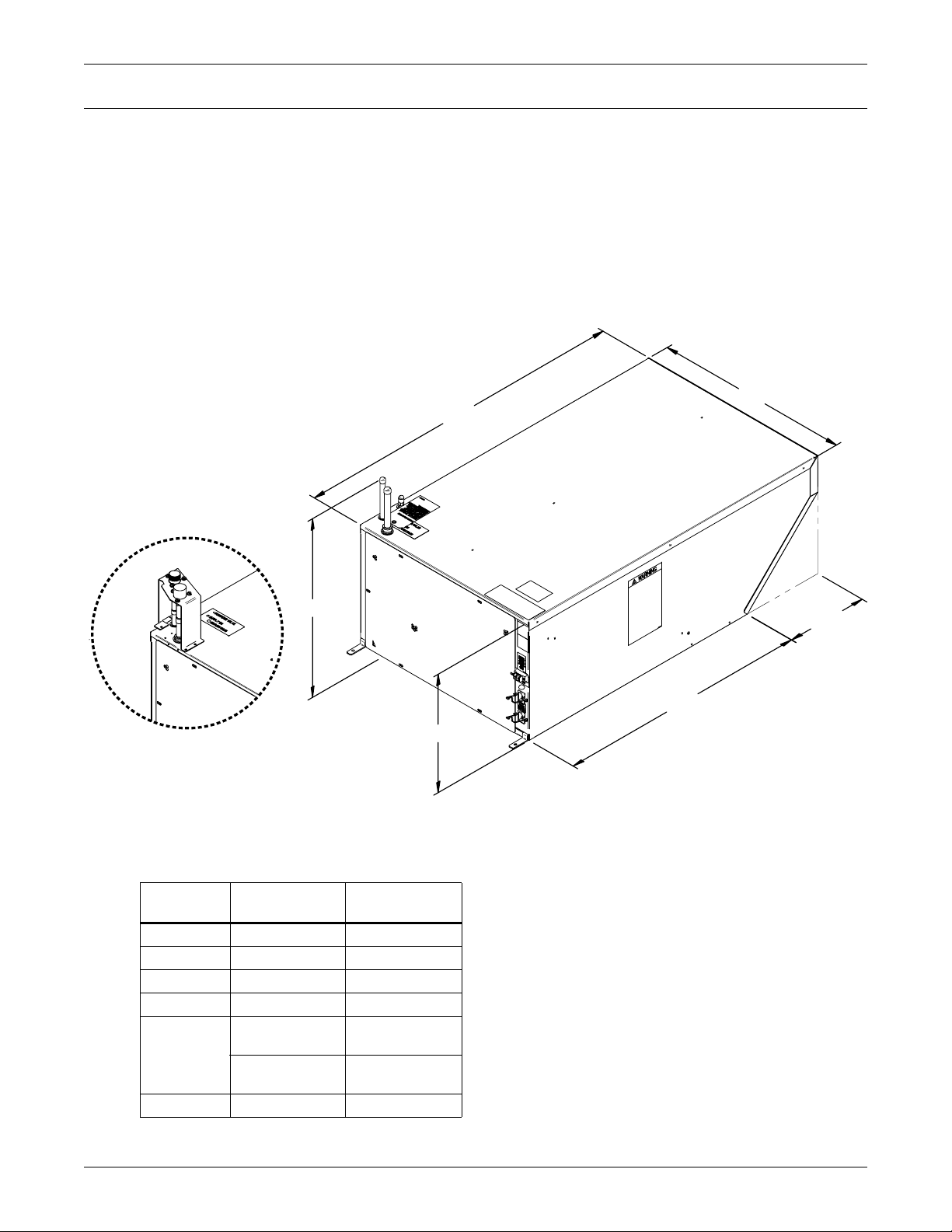
The Liebert XDV is engineered to fit atop computer enclosure cabinets. Figure 8, below, illustrates
the unit’s dimensions and the location of pipes, the fan tray and power connections. (An optional kit is
available to permit suspending the Liebert XDV from either Unistruts or from the overhead structure; see 5.2 - Suspended Mounting Method.).
Figure 8 Liebert XDV dimensions
DT
Mechanical Considerations
W
Liebert XDV With
Pre-charged Option
(all dimensions except piping
height are the same as for the
hard-piped setup, see Table 2)
Table 2 Dimensional data
Illustration
Key Dimension
DT Depth Top 39-1/2 (1003)
DB Depth Bottom 29-5/8 (752)
W Width 22-7/8 (581)
H Height 14 (356)
Piping Height,
PH
DF Depth Front 9-7/8 (250)
hard-piped
Piping Height,
one-shot option
PH
DF
DB
H
DPN000770
Page 2, Rev. 6
Liebert XDV With Hard-piped Arrangement
Measurement,
in (mm)
18-5/8 (473)
19-5/8 (498)
8
Page 15
4.2 Changing the Air Intake Location
The Liebert XDV comes from the factory with the air intake on the rear of the unit. If required for
your application, this can be changed so that the Liebert XDV takes in heated air from the bottom.
This is done more easily and safely before the unit is mounted on a computer cabinet.
WARNING
!
Risk of high-speed moving parts. Can cause death, injury and equipment damage.
Before opening the Liebert XDV, shut the unit off and disconnect all electrical power. Wait for
the Liebert XDV’s fans to stop rotating before beginning to open the unit.
To change the air intake:
1. Loosen the six screws holding the grille on the rear of the Liebert XDV (see Figure 9).
2. Remove the grille and lay it aside for use later.
3. Remove the channel bracket holding the two solid metal plates to the bottom of the Liebert XDV.
It is secured with two screws, one on either end.
4. Lift the two solid plates out of the bottom of the Liebert XDV.
5. Optional—replace the channel bracket, securing it with the two screws removed in Step 3.
6. Lay the perforated grille down with the screws pointing up
7. Lay the two solid plates on the grille with the screws through the matching holes of the plates.
8. Hold the grille and plates together and attach the assembly to the rear of the Liebert XDV with
the screws.
Figure 9 Changing the Liebert XDV’s air intake location
Mechanical Considerations
Solid
plates
Grille
Remove rear inlet grille, taking care not to loosen
the screws. Remove screws and channel bracket
from base of unit, remove solid plates. Using the
screws from the rear grille, reinstall the solid
plates on the exterior rear of the unit.
Place rear grille in a secure area for future use.
9
Page 16

5.0 MOUNTING THE LIEBERT XDV
The Liebert XDV module must be securely attached to the top of the computer cabinet or, alternatively, suspended above the cabinet. For mounting atop the computer cabinet, see 5.1 - Mounting
the Liebert XDV on Top of the Cabinet; to hang the Liebert XDV above the computer cabinet,
refer to 5.2 - Suspended Mounting Method. Be sure to follow all applicable codes.
WARNING
!
Risk of top-heavy cabinet falling. Can cause equipment damage, injury or death.
A lightly loaded cabinet may become top-heavy after a Liebert XDV is mounted on it, causing
the cabinet to tip over, possibly resulting in serious injury.
Before beginning to place the Liebert XDV on the cabinet, ascertain whether the cabinet or rack
requires additional stabilization, and secure the cabinet to the floor if necessary to prevent tipover.
Always use at least two persons to mount the Liebert XDV on top of a cabinet.
5.1 Mounting the Liebert XDV on Top of the Cabinet
The Liebert XDV may be installed on a computer cabinet by securing it with either the two included
bolts, the two included clips or both the bolts and clips.
The Liebert XDV has mounting holes below the fans that match holes in the Liebert Foundation computer system cabinet. Other cabinets may require that holes be drilled to accommodate the bolts or
the clips.
Mounting the Liebert XDV
5.1.1 Bolting Liebert XDV to Top of Cabinet
To mount the Liebert XDV:
1. With at least one additional person, lift the Liebert XDV and set it down on top of the cabinet. The
front edge of the Liebert XDV should be even with the front edge of the cabinet. See Figure 10.
Figure 10 Positioning the Liebert XDV
CORRECT
Liebert XDV
is flush with
front edge
of rack
Computer
cabinet or
rack
2. If your cabinet has mounting holes matching those on the Liebert XDV, align the Liebert
XDV properly and insert the bolts from the bottom of the cabinet and secure them to the factoryinstalled cage nuts (see Figure 11). Tighten the bolts.
If your cabinet’s mounting holes do not match those on the Liebert XDV, drill holes as
required. To prevent metal shavings and particles from falling into the equipment in the cabinet
or into the Liebert XDV, use a vacuum or other method to collect them while drilling the holes.
After drilling the holes, insert bolts from the bottom of the cabinet and secure them to the factoryinstalled cage nuts (see Figure 11). Tighten the bolts.
If also using mounting clips in conjunction with bolting method above, see 5.1.2 - Using Sup-
plied Clips for Mounting.
INCORRECT
Liebert XDV
is too
far from
front edge
of rack
Computer
cabinet or
rack
XX
INCORRECT
Liebert XDV
hangs over
front edge
of rack
Computer
cabinet or
rack
10
Page 17

Figure 11 Mounting hole locations—standard mounting method
Rear of
Liebert XDV
Fan tray removed to show mounting
location(s) of 1/4" - 20 bolts
Mounting the Liebert XDV
Front of
Liebert XDV
Bolt 1/4" - 20
(2 places, typ.)
Figure 12 Mounting hole locations—alternate mounting points
Front of Liebert XDV
13/16"
(21mm)
1
1
AA
20-5/8"
(524mm)
AA
7-1/16"
(179mm)
BB
11"
(279mm)
20-7/8"
1
(530mm)
Notes
1. These dimensions may be
used when attaching Liebert
XDV to a non-Liebert cabinet.
2. Drill clearance holes as
indicated:
"A" #10-32 screw--0.22" (5mm)
diameter
"B" 1/4 - 20 bolt--0.28" (7mm)
diameter.
3. Field to supply #10/32 screws,
quantity of 4.
Factory to supply 1/4 - 20 bolts,
quantity of 20.
Rear of Liebert XDV
BOTTOM VIEW
DPN000770
Page 7, Rev. 5
11
Page 18

5.1.2 Using Supplied Clips for Mounting
1. Attach the mounting clips to the back of the Liebert XDV by fitting them into the machined slots.
Tighten the bolts.
2. If your cabinet has mounting holes in position for the clips, align the Liebert XDV
properly and insert the bolts from the bottom of the cabinet and secure them with the included
lock washers and nuts (see Figure 13). Tighten the nuts.
If your cabinet’s mounting holes do not match the clips, drill holes as required. To preventing metal shavings and particles from falling into the equipment in the cabinet or into the Liebert
XDV, use a vacuum or other method to collect them while drilling the holes.
After drilling the holes, insert bolts from the bottom of the cabinet and secure them with lock
washers and nuts (see Figure 13). Tighten the nuts and bolts.
If also using mounting clips in conjunction with bolting method above, see 5.1.1 - Bolting Lie-
bert XDV to Top of Cabinet.
Figure 13 Mounting clip placement
Mounting the Liebert XDV
Liebert Foundation shown
without panels for clarity.
Mounting holes shown
may not match all cabinets.
Mounting Clip
(two supplied)
12
Page 19

5.2 Suspended Mounting Method
The Liebert XDV also may be mounted above the cabinet by suspending it either from overhead components or from Unistruts above the cabinets (see Figures 15 and 16). An optional kit available from
Liebert will simplify mounting the Liebert XDV above the computer cabinet.
Each suspended-mounting method requires that the supporting components be strong enough to support the Liebert XDV’s weight with coolant, 79 lb. (36kg). Each method also requires that the Liebert
XDV’s placement above the computer cabinet meets the criteria in Figure 10.
To ensure efficient cooling, a baffle or similar object must be installed between the suspended Liebert
XDV and the computer cabinet (see Figure 16). The baffle’s purpose is to prevent the Liebert XDV
from drawing in the cooled air that it has just discharged.
Figure 14 Dimensions—optional external hanging brackets
7/16"
(11mm)
H
Mounting the Liebert XDV
Top View
2-1/2"
(64mm)
3"
(76mm)
7/8" (22mm)
4"
(102mm)
DPN000770
Front View , Left Side
Table 3 Suspension hardware and bracket dimensional data
Bracket Kit Part # "H"
180427G1 180427G5 20 (508)
180427G11, 180427G15 34-5/16 (872)
180427G22*
* Bracket kit for double-stacked Liebert XDVs
18-11/16 (474)
33 (838)
Liebert XDV Units
to be Suspended Brackets in Kit
14
520
14
520
28
Pg. 10, Rev. 5
13
Page 20

5.2.1 Suspending the Liebert XDV from Unistruts
The Liebert XDV may be bolted to customer-supplied Unistruts. The height of the Unistruts above
the computer cabinet must be adequate to accommodate the combined height of the Liebert XDV and
the baffle.
To suspend the Liebert XDV from a Unistrut system:
1. Bolt the hangers to each corner of the Liebert XDV, inserting the Liebert-supplied bolts into
factory-fabricated holes in the bottom of the Liebert XDV. See Figure 15.
2. Tighten all bolts firmly, taking care not to overtighten the bolts.
3. Using a lifting mechanism, raise the Liebert XDV with brackets attached, to the proper height
and bolt the brackets to the Unistruts.
Figure 15 Suspending Liebert XDV from Unistruts
Mounting the Liebert XDV
Bolt 3/8" -16; nut and
washer provided in kit
Unistrut
(field-supplied)
Bolt a bracket to each
corner of the Liebert XDV
5.2.2 Suspending the Liebert XDV from Overhead Structures
To suspend the Liebert XDV from the overhead structure using the optional overhead mounting kit
and field-supplied all-thread bolts:
1. Bolt the hangers to each corner of the Liebert XDV, inserting the Liebert-supplied bolts into
factory-fabricated holes in the bottom of the Liebert XDV.
2. Tighten all bolts firmly, taking care not to overtighten the bolts.
3. Install the field-supplied all-thread bolts into the overhead structure, securing them to
components so they will match the layout of the brackets
4. Using a lifting mechanism, raise the Liebert XDV inserting the all-thread bolts through the bolt
holes in the brackets
5. Install field-supplied nuts and washers, on the all-thread bolts, placing them on the bolts at the
level desired for hanging the Liebert XDV.
6. Again using field-supplied nuts and washers, secure the Liebert XDV to the all-thread bolts.
7. Tighten the nuts until the Liebert XDV is level and well-secured.
14
Page 21

Figure 16 Suspending Liebert XDV from the overhead structure
3/8"-16 all-thread bolts,
field-supplied, typical
Hanging Liebert XDV unit
To prevent bypass air
from recirculating
through the Liebert XDV
without it passing through
the cabinet, this space
between the hanging
XDV and the cabinet
must be blocked.
Mounting the Liebert XDV
15
Page 22

5.3 Mounting Liebert XDVs in Stacked Setup
Liebert designed the Liebert XDV to permit mounting the units in a stacked arrangement to increase
the system’s heat-removal. Stacking may be done either during the original system or added later to
an existing configuration.
Stacking Liebert XDVs is possible when suspending units from either Unistruts or from the overhead
structure. Hanger brackets are available in two lengths to ease hanging Liebert XDVs in a stacked
arrangement.
The upper Liebert XDV must be positioned forward of the front of its companion Liebert XDV for efficient heat removal (see Figure 17).
Figure 17 Stacking configuration offset
Mounting the Liebert XDV
Hanging brackets suspend
stacked Liebert XDVs from either
Unistruts or from roof structure
Rear of Liebert XDVs
FRONT
OF
CABINET
Upper Liebert XDV must
line up with front edge of
lower Liebert XDV
Lower Liebert XDV must line up
with front edge of the cabinet
(space between Liebert XDV and
cabinet must be blocked to prevent
recirculation of cooled air
For details on preventing
recirculation, see Figure 16.
16
Page 23

5.3.1 Hanging Stacked Liebert XDVs from Unistruts
A
t
Because the upper Liebert XDV in a stacked arrangement must be positioned farther forward than
the lower Liebert XDV, two sets of Unistruts are required. The second set of Unistruts must be
installed 9-7/8 inches (251mm) forward of the first set. This arrangement positions the stacked Liebert XDVs so that they meet the air-intake criteria shown in Figure 10 and Figure 17.
After installing the Unistruts at the proper location, hang the Liebert XDVs as outlined in 5.2.1 -
Suspending the Liebert XDV from Unistruts.
Figure 18 Attach hanger brackets to Liebert XDV for stacked arrangement
ttach hanger brackets
o each corner of each
Liebert XDV. This
arrangement permits
mounting from either
Unistruts or from overhead
structure.
Mounting the Liebert XDV
10 - 32 x 5/8" length;
factory-supplied
1/4 - 20 x 5/8" length typical, 2;
factory-supplied
10 - 32 x 5/8" length typical, 3;
factory-supplied
Figure 19 Stacked Liebert XDVs suspended from Unistruts
Unistrut field-supplied
upper Liebert XDV: 1
lower Liebert XDV: 2
Bolt 3/8"- 16,
nut and washer
factory-supplied
17
Page 24

5.3.2 Hanging Stacked Liebert XDVs from the Overhead Structure
Because the upper Liebert XDV in a stacked arrangement must be positioned farther forward than
the lower Liebert XDV, the place where the hangers attach to the overhead structure must be offset
accordingly. The second row of attachment locations must be 9-7/8 inches (251mm) forward of the first
row of hanger mounting locations. This arrangement positions the stacked Liebert XDVs so that they
meet the air-intake criteria shown in Figure 10 and Figure 17.
After determining the proper for attachment to the overhead structure, hang the Liebert XDVs as
outlined in 5.2.2 - Suspending the Liebert XDV from Overhead Structures.
Figure 20 Stacked Liebert XDVs ready for suspension from overhead structure
3/8"-16 All-thread bolts,
field-supplied (four
required per Liebert XDV)
Mounting the Liebert XDV
18
Page 25

6.0 PIPING
6.1 European Union Fluorinated Greenhouse Gas Requirements
Stationary air conditioning, refrigeration, heat pump equipments and stationary fire protection systems in the European Community market and operating with fluorinated greenhouse gases (f-gas),
such as R407C, R134a, R410A, must comply with the F-Gas Regulation: (EC) No. 842/2006 (F-gas).
The regulation prohibits, among other actions, venting fluorinated greenhouse gases to the atmosphere.
The F-Gas Regulation requires operators to use use all measures that are technically feasible and do
not entail disproportionate cost to prevent leakage of these gases, to test for leakage regularly and to
recover f-gas before disposing of equipment, as well as during service and maintenance.
Refer to the full regulation for additional details.
6.2 System Connection Configuration
If possible, connect the Liebert XDV modules to Liebert XDPs or Liebert XDCs in an interlaced configuration (see Figure 21). In an interlaced configuration, half the cooling units in an aisle are connected to one Liebert XDP or Liebert XDC and the other half in that aisle are connected to another
Liebert XDP or Liebert XDC. Such interlaced piping will keep half the Liebert XDV units operating
and maintain even cooling in the conditioned space should one of the Liebert XDP or Liebert XDC
units fail.
However, in a system with just one Liebert XDP or Liebert XDC, connect Liebert XDV modules in a
non-interlaced configuration (see Figure 22).
Piping
Figure 21 Typical Liebert XDV piping—interlaced connections
TOP VIEW—NOT TO SCALE
Liebert XDV ALiebert XDV BLiebert XDV ALiebert XDV
Liebert
XDP/Liebert
Supply A
Return A
Return B
Supply B
Liebert
XDP/Liebert
Liebert XDV BLiebert XDV ALiebert XDV BLiebert XDV
NOTE: Line size does NOT
indicate pipe size difference.
B
A
19
Page 26

Figure 22 Typical Liebert XDV piping—non-interlaced connection
Piping
TOP VIEW—NOT
TO SCALE
Return
Supply
Liebert
XDP/Lie-
Liebert XDV
A
6.2.1 Piping Connections to Liebert XDP or Liebert XDC
Refer to site specific drawings for general locations of the piping connections. For Liebert XDV connection locations, refer to Figures 1 and 24.
6.3 Connection Methods and Points
The assembly and connection means used for piping in the Liebert XD system are the same as those
used in conventional refrigeration systems. Observe all standard practices during installation and
startup to prevent damage and contamination. All piping must be ASTM Type "L" copper pipe.
For hard-piped Liebert XDVs, the supply piping connection is 1/2" OD copper pipe, and the return
piping connection is 5/8" OD copper. For Liebert XDVs with the pre-charged option, both supply and
return fittings are one-shot connections. These fittings contain pressurized R-134a refrigerant inside
the Liebert XDV.
Liebert XDV ALiebert XDV
A
Liebert XDV
A
20
Page 27

Figure 23 Hard-piped connection diagram
Return Main
(seen from end )
2-1/8" O .D.
or 2-5/8" O.D.
Piping
Recomm ended Arc
Acceptable Arc
5/8” Refrigerant -Grade
Full-Port Ball Valve
Field-Supplied and
Field-Installed
Copper Tubing
Total length of each
line from Liebert XDV
to Main; not to exceed
72" (1829mm)
Supply Main
(seen from end )
1-1/8" O.D.
or 1-3/8" O.D.
1/2” Refrigerant-Grade
Full-Port Ball Valve
Field-Supplied and
Field- Installed
Refer to Table 4 for details.
Top of Liebert XDV
Right Side
of Liebert XDV
21
Page 28

6.4 Hard Piped Connection Sizes
V
Supply piping connection is 1/2" OD copper pipe and return piping connection is 5/8" OD copper.
6.4.1 Holding Charge—Hard-Piped Units
The Liebert XDV in hard-piped configuration is shipped with a low-pressure holding charge (about 30
psi) of nitrogen to prevent oxidation and moisture. This must be vented before removing the caps on the
ends of the supply and return piping.
To vent the holding charge:
1. Find the Schrader valve that contains the nitrogen holding charge in the Liebert XDV (see
Figure 24).
2. Vent the holding charge by depressing the pin in the valve.
3. Replace and secure the cap on the Schrader valve.
Figure 24 Piping location and connection sizes—hard-piped units
Top View of
Liebert XDV
Supply
Connection
1/2"
Schrader Valve
SCHRADER VALVE
Piping
2-3/8"
(60mm)
(19mm)
1-1/ 8"
(29mm)
3/4"
2-5/8"
(67mm)
SUPPLY (IN)
RETURN (OUT)
Return
Connection
5/8"
Rear of Liebert XD
DPN000770
Page 4, Rev. 5
22
Page 29

Figure 25 Schrader valve location for venting holding charge
Front of Liebert XDV
Top of Liebert XDV
Piping
Schrader
Valve
SCHRADER VALVE
SUPPLY (IN)
RETURN (OUT)
Supply pipe
connection
(1/2" OD)
Return pipe
connection
(5/8" OD)
6.4.2 Brazing Preparations—Hard-Piped Units
After the holding charge for a hard-piped Liebert XDV has been vented, a torch can be used to remove
the caps over the ends of the supply and return lines.
During brazing, the lines must be filled with flowing dry nitrogen to prevent excessive oxidation and
scale formation inside the piping. Prevailing good refrigeration practices must be employed for piping
supports, leak testing, dehydration and charging. Failure to use good system practices may result in
damage to the system. Refer to the ASHRAE refrigeration handbook for general good-practice refrigeration piping.
6.5 Recommended Piping Size
NOTICE
To minimize the amount of refrigerant required, do NOT oversize the piping.
Connect the main pipes between the Liebert XDV branch piping and the Liebert XDP or Liebert XDC
according to Table 4. Elbows and restrictions must be minimized to ensure good fluid flow.
Please see Table 4 below for recommended pipe sizes and Figure 3 for piping segment locations.
Rear of XDV
23
Page 30

Table 4 Branch piping sizes for refrigerant loop
Pipe Function Size / Equivalent Pipe Length
Liebert XDP/Liebert XDC supply line, from
Liebert XDP/Liebert XDC supply
to farthest Liebert XDV
Liebert XDP/Liebert XDC return line, from
farthest Liebert XDV
to Liebert XDP/Liebert XDC return
From Liebert XDV supply to supply line of
Liebert XDP/Liebert XDC
From Liebert XDV return to return line of
Liebert XDP/Liebert XDC
1-1/8" OD (1.025" ID) for lengths up to 60 feet (18m)
1-3/8" OD (1.265" ID) for lengths over 60 but less than 175 feet (18 to 53m)
2-1/8" OD (1.985" ID) for lengths up to 60 feet (18m)
2-5/8" OD (2.465" ID) for lengths over 60 but less than 175 feet (18 to 53m)
1/2" OD (0.430" ID) for lengths up to 6 feet (1.8m)
5/8" OD (0.545" ID) for lengths over 6 feet but less than 35 feet (1.8-10.6m)
5/8" OD (0.545" ID) for lengths up to 6 feet (1.8m)
7/8" OD (0.785" ID) for lengths over 6 feet but less than 35 feet (1.8-10.6m)
6.6 Connection Methods—One-Shot Connections
The assembly and connection means used for piping in the Liebert XD system are the same as those
used in conventional refrigeration systems. Observe all standard practices during installation and
startup to prevent damage and contamination.
Both supply and return fittings may be supplied with optional, one-shot connections. These fittings
contain pressurized R-134a refrigerant inside the Liebert XDV.
CAUTION
!
Risk of sudden refrigerant discharge. Can cause injury and loss of charge.
If the optional pre-charged option is chosen, the Liebert XDV unit is shipped with a full
charge of R-134a refrigerant under pressure. Do not remove the pipe caps or plugs before the
unit is ready for connection to Liebert XD Piping.
Supply and return fittings on the pre-charged Liebert XDV units are one-shot connections. Do
not disconnect one-shot connections after they have been connected. Disconnection will
release pressurized R-134a refrigerant from the Liebert XDV.
Piping
If the unit includes the optional, factory-installed, one-shot style connections, proceed with 6.7 - Field
Installation of Liebert Flex Pipe Kit on Liebert XDV and see Figure 26.
If the unit does not include flex piping, refer to 6.4.1 - Holding Charge—Hard-Piped Units.
Figure 26 Piping location and connection sizes—pre-charged units with one-shot connections
Top Vi e w
Supply
Connection
1/2"
Detail
Area “A”
Return
Connection
5/8"
Detail “A”
24
Page 31

6.6.1 Refrigerant Charge—Pre-Charged Option
Liebert XDVs with the pre-charged option are equipped with one-shot connections on the supply and
return fittings. These contain a charge of R-134a refrigerant under pressure within the unit. This
charge must not be vented.
Do not remove the pipe caps or plugs before the unit is ready for connection to Liebert XD Piping. Do
not disconnect one-shot connections after they have been connected.
6.7 Field Installation of Liebert Flex Pipe Kit on Liebert XDV
If you are not performing a service installation or a field-retrofit, skip this section and proceed with
the instructions in 6.8 - Connecting Liebert XD Flex Pipe to Liebert XDV Modules.
Liebert Flex Pipe kits are available in lengths of 4, 6, 8 and 10 feet (1.2, 1.8,2.4 and 3 meters). Connection style to the unit end may be straight or 90 degrees. Connection to the prefab piping assembly is a
threaded coupler. For data on acquiring the correct kit for your installation, see Table 7.
Figure 27 Liebert XD Flex Pipe dimensions—straight and 90-degree connections
Piping
Connection
to Prefabricated
Piping assembly
Length
4, 6, 8 or 10 feet
(1.2, 1.8, 2.4 or 3 meters)
(1.2, 1.8, 2.4 or 3 meters)
Connection
to Prefabricated
Piping assembly
Length
4, 6, 8 or 10 feet
Straight Connection
Connection to XD Cooling Unit
(One-Shot Coupling)
DPN000780
Pg. 1, Rev. 1
6.8 Connecting Liebert XD Flex Pipe to Liebert XDV Modules
1. Remove the caps on the supply and return lines on the top of the Liebert XDV.
2. Lubricate the threads, diaphragm and O-ring with one or two drops of mineral oil.
3. Connect the line-set coupling finger-tight.
4. Make sure the Schrader valve is properly oriented; refer to the label on the top of the Liebert
XDV.
5. Hold the backup hex nut with a wrench while tightening the swivel nut.
6. Tighten the swivel nut on the female coupling until it is seated or a definite resistance is felt.
7. Once a definite bottoming resistance is felt (as in metal to metal), place a mark lengthwise from
the swivel nut to the backup hex and tighten the swivel nut on the female coupling an additional
1/4 turn.
8. Tighten both the supply fittings and the return fittings to 35-45ft/lb (47-61Nm).
9. Mark the female and male coupler with for future reference.
90-Degree
Connection
90° Connection to XD Cooling Unit
(One-Shot Coupling)
DPN000780
Pg. 2, Rev. 1
25
Page 32

6.9 Connecting a Liebert XDV with Liebert Flex Pipe to an Operational Liebert XD System
NOTICE
Before connecting the Liebert XDV with Liebert Flex Pipe to the prefabricated piping mains,
check the whole system for leaks.
Check the Liebert XDV to ensure that the unit has no refrigerant leaks.
Read all instructions before beginning installation.
Tools Required
• Two adjustable wrenches, with a maximum adjustment size of 2-1/2 inches
•Two ladders
• Lifting mechanism if the Liebert XDV is going to be suspended above the cabinet
NOTE
This operation requires two or more people.
1. Determine the port location of the supply and return piping overhead
2. Make sure the service valve for each port is closed
3. Remove cap for only the required ports. Do not remove caps from the unused ports.
4. Once Step 3 has been completed, remove the pipe plugs that are supplied on the Liebert Flex
Pipe on the Liebert XDV.
Piping
Figure 28 Liebert XD prefabricated piping assembly
Return Main
Supply Main
Threaded Cap
(Typical)
5. Use system refrigerant to lubricate the face of the male coupling half, including the poppet valve
face and the stainless steel delta ring.
6. Thread the return couplers together, the larger of the two couplers (Liebert Flex Pipe and return
main).
7. Use one of the adjustable wrenches to hold the fixed side of the female coupler on the Liebert XDV
stationary. With the other adjustable wrench, tighten the collar onto the coupler.
Tighten these only until the force required to tighten abruptly increases. See Figure 29.
Service Valve, typical
(all ports)
NOTICE
Do not overtighten the couplers. Overtightening of couplers will damage the couplers.
26
Page 33

Figure 29 Detail view of Liebert XD Flex Pipe and prefabricated piping port
Tighten collar
Supply Side Torque Range for
1/2" coupler is 22.1 to 25.8 lb/ft (30-35Nm)
Return Side Torque Range for
1" coupler is 59 to 62.7 lb/ft (80-85Nm)
with wrench.
DO NOT
OVERTIGHTEN!
Hold threaded coupler here
with a wrench to keep the
pipe stationary while tightening
collar with another wrench.
Flex Pipe
8. Repeat Steps 6 and 7 for the smaller coupler (supply line).
9. Once the supply and return connections are completed, check to make sure the Liebert XDV fan
power switches are Off, then connect the power cords to their power sources.
10. Turn the fan switches on. Ensure that the fans operate.
11. Open the return service valve first, then open the supply service valve.
With the fans running, cool air is discharged from the front of the Liebert XDV.
Piping
Service Valve
Note:
Make sure the valve
is closed before attaching
flex pipe to the system.
Figure 30 Liebert XD system with prefabricated piping assembly and Liebert XD Flex Pipe
Return Service Valve
Make sure valve is
open after system
leak check
Supply Service Valve.
Make sure valve is
open after system
leak check
Return
Main
Supply Main
Return Liebert
Flex Pipe
from XDV unit
27
Supply Liebert Flex Pipe
from Liebert XDV unit
Page 34

6.10 Disconnecting a Liebert XDV With Liebert Flex Pipe From a Liebert XD System
CAUTION
!
Risk of sudden discharge of pressurized refrigerant. Can cause equipment damage or injury.
Do not disconnect threaded refrigerant couplers at the unit cabinet end without relieving
system pressure. Reclaim any refrigerant during removal of unit from system.
NOTICE
Before uninstalling a Liebert XDV with Liebert Flex Pipe from the prefabricated piping
mains: With the fans running, close the supply service valve, wait approximately
two minutes, then close the return service valve.
Removing a Liebert XDV from above a cabinet will require two people. Read all instructions
before beginning.
Tools Required
• Two adjustable wrenches, maximum adjustment size of 2-1/2 inches
•Two ladders
• Phillips head #2 screwdriver
• Lift mechanism, if the Liebert XDV is suspended above cabinet
1. Ensure the Liebert XDV fan switches are both On and the fans are operational.
2. Close the service valve in the supply line to the Liebert XDV (smaller coupler).
3. With the Liebert XDV fans running, wait two minutes.
4. Close the service valve in the return line to the Liebert XDV (larger coupler).
5. Turn the fan power switches to the Off position. Once the fan switches are turned Off, unplug the
power cords from their power source.
6. Locate and have at the ready the caps and plugs for both ends of the supply and return couplers.
7. Loosen the female supply coupler from the male supply coupler (smaller coupler). This requires
two adjustable wrenches. Refer to Figure 29.
8. The Liebert XDV side of the female coupler must be held stationary while the collar on the
coupler is being loosened. Refer to Figure 29.
9. Disconnect the coupler.
Piping
Figure 31 Profile view of the Liebert XD system with one-shot connections
One-Shot Connections
One-Shot Support Bracket
Fan Power
Switches
Rear of the XDV
Serial Tag
Liquid Sensing
(optional)
Disconnect wiring
prior to moving XDV
Primary and
Secondary
IEC Power
Cord
10. Place the protective dust cap and plug back onto both ends of the coupler on the Liebert XDV and
the port pipe.
Return
Line
Service
Val ve
Supply
Line
28
Page 35

Figure 32 Piping mains without Liebert XDV and Liebert Flex Pipe
Piping
11. Repeat Steps 8 through 10 for the return coupler (larger coupler).
12. Carefully lay the Liebert Flex Pipe on the top of the Liebert XDV.
NOTICE
Risk of permanent damage to the flex pipes. Do not fold or bend flex pipe tightly.
13. Carefully unbolt the Liebert XDV from the cabinet or hanging bracket, if applicable.
14. With the help of another person, carefully lower the Liebert XDV from the cabinet or hanging
bracket onto a stable surface.
6.11 Insulation
To minimize the possibility of condensation, insulate all piping between the Liebert XDV and the Liebert XDP or Liebert XDC.
29
Page 36

7.0 ELECTRICAL
The unit must be installed in accordance with national wiring regulations. Refer to the unit’s serial
tag for electrical requirements. Refer to Table 5 for details.
Replacement of any wiring or supply cord must be performed only by the manufacturer, the manufacturer’s service agent or a similarly qualified person.
7.1 Connecting High Voltage Cables for CSA/C-US Certified Units
WARNING
!
Risk of electric shock. Can cause injury or death.
Disconnect all local and remote electric power before working within the unit.
Connect IEC power cords to each receptacle on the Liebert XDV and to power sources. If only one
power source is available, then only the power connection labeled “SECONDARY” should be connected to the power source. See Figures 33 and 34 for location of power connections.
Figure 33 Liebert XDV electrical connections for CSA-approved units
60Hz MODELS ONLY.
FIELD WIRING
CONNECTIONS
AT TERMINAL STRIP
TO BE N.E.C. CLASS 2
USE SWITCH
CONTACTS WITH 75 V.A.
MINIMUM
50Hz MODELS ONLY.
FIELD WIRING
CONNECTIONS
AT TERMINAL STRIP
FOR SAFETY EXTRA
LOW VOLTAGE CIRCUITS
ONLY. USE SWITCH
CONTACTS RATED
75 V.A. M INIMUM,
24 VOLTS A C
MAXIMUM.
1774241 P1 REV 1
Electrical
82 83
A
M
P
PRIMARY
POWER
SOURCE
SECONDARY
1774241P1
A
M
P
Rear of
Liebert XDV
Condensate Detection
Dry Contacts – Low
Voltage Connections
Primary
Circuit
Breaker
IEC Primary and
Secondary
Power Inlet
Secondary
Circuit Breaker
Right Side of Liebert XDV
60Hz MODELS ONLY
Field wiring connections
at terminal strip to be NEC
Class 2. Use switch contacts
with 75VA minimum rating.
50Hz MODELS ONLY
Field wiring connections
at terminal strip for safety extra
low voltage circuits only. Use
switch contacts rated 75VA
minimum, 24VAC maximum.
Rear of Liebert XDV
30
Page 37

Figure 34 Liebert XDV electrical connections for CE-approved units
60Hz MODELS ONLY.
FIELD WIRING
CONNECTIONS
AT TERMINAL STRIP
TO BE N.E.C. CLASS 2
USE SWI TCH
CONTACTS WITH 75 V.A.
MINIMUM
50Hz MODELS ONLY.
FIELD WIRING
CONNECTIONS
AT TERMINAL STRIP
FOR SAFETY EXTRA
LOW VOLTAGE CIRCUITS
ONL Y. USE SWI TCH
CONTACTS RATED
75 V.A. MINIM UM,
24 VOLTS AC
MAXIMUM.
1774241 P1 REV 1
82 83
Condensate Detection
Dry Contacts – Low Voltage
Connections
Knockout
for Optional
Wiring
Electrical
60Hz MODELS ONLY
Field wiring connections
at terminal strip to be NEC
Class 2. Use switch contacts
with 75VA minimum rating.
50Hz MODELS ONLY
Field wiring connections
at terminal strip for safety extra
low voltage circuits only. Use
switch contacts rated 75VA
minimum, 24VAC maximum.
PRIMARY
POWER
SOURCE
SECONDARY
1774241P1
Primary and
Secondary
Power Cords
FACTORY-SUPPLIED
POWER CORDS
(straight-on and profile)
If the factory-supplied power
cords do not match with the
user’s electrical outlets, a
suitable adapter must be
field-provided.
31
Page 38

7.2 Connecting Low Voltage Wiring—Optional
Low voltage connections to the Liebert XDV are available only on units with the optional condensate
detection feature. The low voltage connections are on the right side of the electrical connections box,
just above the power connections (see Figure 35). These dry contacts can to be connected to a monitoring unit, such as Liebert’s SiteScan®.
For units equipped with condensate detection, make low voltage connections according to site-specific
drawings. The unit must be installed in accordance with national wiring regulations.
Figure 35 Low voltage connections
Condensate Detection Connections
Rear View of Liebert XDV
60Hz MODELS ONLY.
FIELD WIRING
CONNECTIONS
AT TERMINAL STRIP
TO BE N.E.C. CLASS 2
USE SWITCH
CONTACTS WITH 75 V.A.
MINIMUM RATING.
50Hz MODELS ONLY.
FIELD WIRING
CONNECTIONS
AT TERMINAL STRIP
FOR SAFETY EXTRA
LOW VOLTAGE CIRCUITS
ONLY. USE SWITCH
CONTACTS RATED
75 V.A. MINIMUM,
24 VOLTS AC
MAXIMUM.
1774241P1 REV 1
Electrical
60Hz MODELS ONLY.
FIELD WIRING
CONNECTIONS
AT TERMINAL STRIP
TO BE N.E.C. CLASS 2
USE SWITCH
CONTACTS WITH 75 V.A.
MINIMUM RATING.
50Hz MODELS ONLY.
FIELD WIRING
CONNECTIONS
AT TERMINAL STRIP
FOR SAFETY EXTRA
LOW VOLTAGE CIRCUITS
ONLY. USE SWITCH
CONTACTS RATED
75 V.A. MINIMUM,
24 VOLTS AC
MAXIMUM.
1774241P1 REV 1
32
Page 39

Installation Checklist and System Fill for Startup
8.0 INSTALLATION CHECKLIST AND SYSTEM FILL FOR STARTUP
8.1 Checklist for Proper Installation
___ 1. Liebert XDV module is properly mounted, secured either to the cabinet, overhead structure or
to the Unistruts.
___ 2. Power cords connected to electrical supply.
___ 3. Low voltage wiring to optional condensate detection on Liebert XDV.
___ 4. Piping from Liebert XDP to Liebert XDV, with isolation valves piped to each Liebert XDV.
a. Hard-piped units connected to prefabricated headers
b. Flex piping connections to prefabricated header assembly, if flex piping is used.
___ 5. Piping insulated.
___ 6. Start the Liebert XDV to ensure proper operation (see 9.1 - Start the Liebert XDV).
___ 7. Shut down the Liebert XDV.
8.2 Charging with Refrigerant and Starting the Liebert XD System
The Liebert XD System must be completely installed before it is charged with refrigerant. After
installation is complete, refer to the Liebert XDP or Liebert XDC user manual for instructions on
charging the Liebert XD modules with refrigerant and starting the system. The complete Liebert XD
system includes all cooling modules, a Liebert XDC or Liebert XDP unit and any other connected
equipment.
33
Page 40

9.0 OPERATION
The Liebert XDV’s fan controls are on the front of the unit, near the fans, for easy access. Each switch
controls the operation of one fan (see Figure 36). The separate switches permit the use of only one
fan at a time, reducing the airflow if the Liebert XDV’s full cooling capacity is not needed.
The Liebert XDV’s primary and secondary circuit breakers are also on the front of the unit. They are
at the top left when facing the Liebert XDV (see Figure 36).
NOTE
One of the Liebert XDV’s fans must be turned on before either the Liebert XDP or Liebert XDC
is switched on.
One of the Liebert XDV’s fans must be operating at all times that the Liebert XDP or Liebert
XDC is operating. Operating either the Liebert XDP or the Liebert XDC without at least one of
the Liebert XDV’s fans rotating may cause a system malfunction.
Figure 36 Fan switches
Operation
Primary and Secondary
Circuit Breakers
9.1 Start the Liebert XDV
The Liebert XDV fans must be on before starting the Liebert XDP or Liebert XDC that will supply
coolant to the Liebert XDVs.
To start the Liebert XDV, press either of the rocker switches to turn on one or both of the Liebert
XDV’s fans.
On/Off Switch
for Right Fan
On/Off Switch
for Left Fan
34
Page 41

10.0 MAINTENANCE
Minimal maintenance is required to keep the Liebert XDV operating at optimal levels. The unit
should be cleaned and checked for damage and worn parts. Suggested maintenance includes:
• Cooling fins—Clean any dust and debris from the cooling fins, taking care not to bend them
• Circulating fans—Clean any dust from the fans.
10.1 Fluorinated Greenhouse Gas Requirements
Stationary air conditioning, refrigeration, heat pump equipments and stationary fire protection systems in the European Community market and operating with fluorinated greenhouse gases (f-gas),
such as R407C, R134a, R410A, must comply with the F-Gas Regulation: (EC) No. 842/2006 (F-gas).
The regulation prohibits, among other actions, venting fluorinated greenhouse gases to the atmosphere.
The F-Gas Regulation requires operators to use use all measures that are technically feasible and do
not entail disproportionate cost to prevent leakage of these gases, to test for leakage regularly and to
recover f-gas during equipment service and maintenance and before disposing of equipment.
Refer to the full regulation for additional details.
10.2 Internal Access
WARNING
!
Risk of high-speed moving parts. Can cause death, injury and equipment damage.
Before opening the Liebert XDV, shut the unit off and disconnect all electrical power. Wait for
the Liebert XDV’s fans to stop rotating before beginning to open the unit.
Maintenance
WARNING
!
Risk of electrical shock. May cause death or injury.
Disconnect all power before working within.
• Turn off the main switch (in the center of the fan tray).
• Remove both power cords from the electrical supply outlets or from the receptacles on the
back of the Liebert XDV.
CAUTION
!
Risk of improper handling. May cause injury.
Use both hands when removing fan tray assembly. Improperly handling the assembly may
cause injury during removal.
The conditions required for sensitive electronic equipment should preclude the accumulation of appreciable amounts of dust in the Liebert XDV. Most of that small amount should be found on the rear
coils, near the air inlet. The rear covers and the fan tray on the front of the Liebert XDV are easily
removed for maintenance. (A wiring diagram is provided on the inside of the fan tray.)
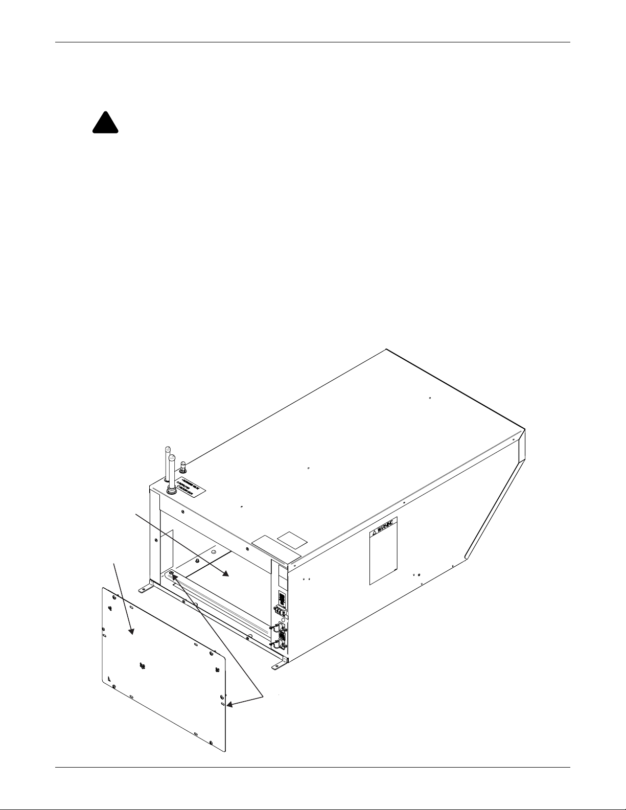
To remove the rear grille:
1. Loosen the six screws holding the grille on the rear of the Liebert XDV.
2. Remove the grille and lay it aside for reinstallation.
35
Page 42

10.2.1 Accessing Internal Electrical Components
1. Disconnect all power inputs.
2. Remove five screws to remove the front electrical panel cover. SeeFigure 37 and 12 of 13
3. Lift off the panel.
Figure 37 Accessing internal electrical components
Maintenance
Edge of the
Fan Assembly
36
Page 43

To remove the fan tray:
1. Remove the front electrical panel cover as described in 10.2.1 - Accessing Internal Electrical
Components.
2. Disconnect the 12-pin connector. Take care not to stretch or stress the electrical wires to the fans.
3. Remove the four screws holding the fan tray on the Liebert XDV.
4. Support the fan tray when removing the last screw to keep it from falling.
5. Set the screws aside for reinsertion after maintenance is completed.
6. Then lift the fan tray up and set it on top of the Liebert XDV or on a nearby surface.
Figure 38 Removing the fan tray
Screws, 5
Maintenance
Mounting
Flange
Fan Tray
To reattach the fan tray:
1. Clean the fan tray to prevent debris from being blown into the computer cabinet.
2. Reconnect the 12-pin connector.
3. Lift the fan tray and fit it against the base of the Liebert XDV housing (see Figure 38).
4. Holding the fan tray against the Liebert XDV housing, insert the screws extracted when removing the
fan tray.
5. Tighten the screws securely.
6. Reconnect power to the Liebert XDV.
37
Page 44

Specifications
11.0 SPECIFICATIONS
Table 5 Liebert XDV10 specifications
XDV10BK--*; XDV10DK--*
XDV10BKP-*; XDV10DKP-*
XDV10BK-E*; XDV10DK-E*
XDV10BKPE*; XDV10DKPE*
XDV10BKR-*; XDV10BKRE*
XDV10DKR-*; XDV10DKRE*
Models
Cooling Capacity
Conditions
Electrical Requirements
Input 120V model: 1ph-60 Hz
Input power connections 2 power connections, each model
Full Load Amps 120V model: 2.0A 230V model: 1.0A
Power consumption,
nominal, watts
Dimensions, inches (mm)
Height – unit only 14 (355) not including pipe connections
Height – including hard
pipe connections
Height – including one-
shot connections
Width 22-7/8 (581)
Depth – Top 39-1/2 (1003)
Depth – Bottom 29-5/8 (752)
Weight, lb (kg)
Unit only 77 (35)
Shipping weight 125 (57)
Installed, with refrigerant 79 (36)
Number of fans 2222
Airflow, Nominal,
3
ft
/ min (m3/ hr)
Audible noise 78 dBa sound power 73 dBa sound power
Pipe Connections (without Liebert Flex Pipe)
Refrigerant supply
from Liebert XDP/ XDC
Refrigerant return
to Liebert XDP/ XDC
Serviceable Parts Fans and electrical components
Cabinet Exterior Finish Black, matte finish, heat-fused powder coat
Options
Condensate sensing
(factory-installed)
Pre-Charged Refrigerant R-134a Refrigerant, one-shot connections
Agency
Approvals CSA 60Hz CSA 50Hz CE 50Hz
* = Revision level of unit
Nominal (98ºF [37ºC] EAT): 10kW / 2.8 Tons
Maximum (106ºF [41ºC] EAT): 11.8kW/3.4 Tons
1000 (1699) with rear inlet. Bottom inlet airflow
may be less, depending on restrictions inside
60 Hz 60 Hz 50 Hz 50 Hz
Capacity Rating is @ 55ºF (13ºC) Entering Fluid Temperature and
50ºF (10ºC) or lower dew point, rear air inlet.
180 190 190 190
cabinet
1/2" OD, Cu, (optional 1/2" threaded coupler flex piping)
5/8" OD, Cu, (optional 3/4" threaded coupler flex piping)
XDV10BT--*; XDV10DT--*
XDV10BTP-*; XDV10DTP-*
XDV10BT-E*; XDV10DT-E*
XDV10BTPE*; XDV10DTPE*
XDV10BTR-*; XDV10BTRE*
XDV10DTR-*; XDV10DTRE*
Nominal (98ºF [37ºC] EAT): 8kW / 2.3 Tons
Maximum (116ºF [47ºC] EAT): 11.8kW/3.4 Tons
230V model:
1ph-60 Hz
18-5/8 (473)
19-5/8 (498)
833 (1415) with rear inlet. Bottom inlet airflow
may be less, depending on restrictions inside
Dry contact outgoing signal
XDV10BS--*; XDV10DS--*
XDV10BSP-*; XDV10DSP-*
XDV10BS-E*; XDV10DS-E*
XDV10BSPE*; XDV10DSPE*
XDV10BSR-*; XDV10BSRE*
XDV10DSR-*; XDV10DSRE*
230V model: 1ph-50 Hz
cabinet
38
Page 45

Specifications
Table 6 Liebert XDV8 specifications
XDV8BT--*; XDV8DT--*
XDV8BTP-*; XDV8DTP-*
XDV8BT-E*; XDV8DT-E*
XDV8BTPE*; XDV8DTPE*
XDV8BTR-*; XDV8BTRE*
XDV8DTR-*; XDV8DTRE*
Nominal (98°F [37°C] EAT): 8kW/ 2.3 Tons
Maximum (103°F [39°C] EAT): 8.8kW/2.5Tons
Models
Cooling Capacity
Conditions
XDV8BK--*; XDV8DK--*
XDV8BKP-*; XDV8DKP-*
XDV8BK-E*; XDV8DK-E*
XDV8BKPE*;XDV8DKPE*
XDV8BKR-*; XDV8BKRE*
XDV8DKR-*; XDV8DKRE*
60 Hz 60 Hz 50 Hz 50 Hz
Nominal (98°F [37°C] EAT): 8.8kW / 2.5 Tons
Maximum (95°F [35°C] EAT): 8.8kW / 2.5 Tons
Capacity rating is @ 55ºF (13ºC) Entering Fluid Temperature and
50ºF (10ºC) or lower dew point, rear air inlet.
Electrical Requirements
Input 120V model: 1ph-60 Hz 230V model: 1ph-60 Hz 230V model: 1ph-50 Hz
Input power connections 2 power connections, each model
Full Load Amps 120V model: 2.0A 230V model: 1.0A
Power consumption,
nominal, watts
180 190 190 190
Dimensions, inches (mm)
Height – unit only 14 (355) not including pipe connections
Height – including pipe
connections
18-5/8 (473)
Width 22-7/8 (581)
Depth – Top 39-1/2 (1003)
Depth – Bottom 29-5/8 (752)
Weight, lb (kg)
Unit only 77 (35)
Shipping weight 125 (57)
Installed, with
refrigerant
79 (36)
Number of Fans 2222
Airflow, Nominal,
3
ft
/ min (m3/ hr)
1000 (1699) with rear inlet. Bottom inlet airflow may
be less, depending on restrictions inside cabinet
833 (1415) with rear inlet. Bottom inlet airflow
may be less, depending on restrictions inside
Audible noise 78 dBa sound power 73 dBa sound power
Pipe Connections (without Liebert Flex Pipe)
Refrigerant Supply
from Liebert
1/2" OD Cu, (optional 1/2" threaded coupler flex piping)
XDP/Liebert XDC
Refrigerant Return
to Liebert XDP/Liebert
5/8" OD Cu, (optional 3/4" threaded coupler flex piping)
XDC
Serviceable Parts Fans and electrical components
Cabinet Exterior
Finish
Black, matte finish, heat-fused powder coat
Options
Condensate sensing
(factory-installed)
Dry contact outgoing signal
Pre-Charged R-134a Refrigerant, one-shot connections
Agency
Approvals CSA 60Hz CSA 50Hz CE 50Hz
* = Revision level of unit
XDV8BS--*; XDV8DS--*
XDV8BSP-*; XDV8DSP-*
XDV8BS-E*; XDV8DS-E*
XDV8BSPE*; XDV8DSPE*
XDV8BSR-*; XDV8BSRE*
XDV8DSR-*; XDV8DSRE*
cabinet
39
Page 46

Table 7 Liebert XD Liebert Flex Pipe assemblies, supply and return
Liebert P/N
90-Degree Connection
Assembly
Length
ft (m)
Description
Liebert XD Flex
Pipe Kit
Liebert P/N
Straight Connection
Assembly
186568G1 186567G1 6 (1.8)
186568G2 186567G2 10 (3.0)
186568G3 186567G3 8 (2.5)
186568G4 186567G4 4 (1.2)
Specifications
Minimum Bend Radius
inches (mm)
Supply Return
7 (178) 8 (203)
40
Page 47

Page 48

Ensuring The High Availability
Of Mission-Critical Data And Applications.
Emerson Network Power, the global leader in enabling business-critical
continuity, ensures network resiliency and adaptability through
a family of technologies—including Liebert power and cooling
technologies—that protect and support business-critical systems.
Liebert solutions employ an adaptive architecture that responds
to changes in criticality, density and capacity. Enterprises benefit
from greater IT system availability, operational flexibility and
reduced capital equipment and operating costs.
While every precaution has been taken to ensure the accuracy
and completeness of this literature, Liebert Corporation assumes no
responsibility and disclaims all liability for damages resulting from use of
this information or for any errors or omissions.
© 2008 Liebert Corporation
All rights reserved throughout the world. Specifications subject to change
without notice.
® Liebert is a registered trademark of Liebert Corporation.
All names referred to are trademarks
or registered trademarks of their respective owners.
Technical Support / Service
Web Site
www.liebert.com
Monitoring
800-222-5877
monitoring@emersonnetworkpower.com
Outside the US: 614-841-6755
Single-Phase UPS
800-222-5877
upstech@emersonnetworkpower.com
Outside the US: 614-841-6755
Three-Phase UPS
800-543-2378
powertech@emersonnetworkpower.com
Environmental Systems
800-543-2778
Outside the United States
614-888-0246
Locations
United States
1050 Dearborn Drive
P.O. Box 29186
Columbus, OH 43229
Europe
Via Leonardo Da Vinci 8
Zona Industriale Tognana
35028 Piove Di Sacco (PD) Italy
+39 049 9719 111
Fax: +39 049 5841 257
Asia
7/F, Dah Sing Financial Centre
108 Gloucester Road, Wanchai
Hong Kong
852 2572220
Fax: 852 28029250
SL-16626_REV06_05-08
Emerson Network Power.
The global leader in enabling Business-Critical Continuity.
AC Power
Connectivity
DC Power
Business-Critical Continuity, Emerson Network Power and the Emerson Network Power logo are trademarks and service marks of Emerson Electric Co.
©2008 Emerson Electric Co.
Embedded Computing
Embedded Power Power Switching & Controls
Monitoring
Outside Plant
Precision Cooling
EmersonNetworkPower.com
Racks & Integrated Cabinets
Services
Surge Protection
 Loading...