

Liebert UPSTATION GXT3X1-6000, UPSTATION GXT3X1-8000, UPSTATION GXT3X1-10000 User Manual
Manual Reference number : 6390010Q En (06/02)
UUPPSSTTAATTIIOONN GGXXTT
TTM
M
33xx1
1
66--88--1100 kkVVA
A
UUsseerr M
Maannuuaall

D
D
D
R
R
R
(06/02) Page iii
This manual describes the following GXT Series UPS models:
EQUIPMENT PART NUMBER
6 kVA GXT 3x1 UPS
GXT3X1-6000
8 kVA GXT 3x1 UPS
GXT3X1-8000
10 kVA GXT 3x1 UPS
GXT3X1-10000
IMPORTANT
All models in the UPS range are si mi lar i n both oper at ion and us e.
If you encoun ter an y problems with the procedu res con tain ed in th is manual you should s eek immediate assistance
from the Liebert Sales Off i ce f rom whom the equi pment was purchased. A ltern ativ ely, contact the Liebert's Cus tomer
Service & Support department at the address shown below:
Liebert Hiross United Kingdom
Customer Serv ice an d S u pport Depart ment
4th Avenue, Globe Park
Marlow-SL7 1YG Buckinghamshire
Telephone +44 1628 403200
Fax +44 1628 403203
This department also arranges serv ice con tracts an d f u ll commissioning s erv ice.

UPStation GXT 3x1 USER MANUAL
Page iv (06/02)

USER MANUAL UPStation GXT 3x1
(06/02) Page v
IMPORTANT SAFETY INSTRUCTIONS
1. SAVE THESE INSTRUCTIONS. THIS MANUAL CO NT AINS IM PO RT ANT SAFET Y INST RUCT IO NS. Read all safety
and operating instructions before operating the Uninterruptible Power System (UPS). Adhere to all warnings on the unit
and in this manual. Follow all operating and user instructions. This equipment can be operated by individuals without
previous training.
2. This product is designed for Commercial/Industrial use only. It is not intended for use with life support and other
designated “critical” devices. Maximum load must not ex ceed that show n on the U PS rating label. T he U PS is
designed for data processing equipment. If uncertain, consult your dealer. See Limited Warranty.
3. This UPS is designed for use on a properly earthed (grounded), 208-240 VAC, 50Hz or 60Hz supply, for installation by
qualified personnel. A qualified electrician must review and approve customer supplied wiring, circuit breakers,
intended loads, and verify correct input, output and earth connections to ensure compliance with technical standards
and local electrical codes of practice. Installation instructions and warning notices only for use by qualified personnel
are located after the UPS operator instructions in this manual.
4. ELECTROMAGNET IC C O MPATIBILITY- The GX T 3x1 6 & 8 & 10 kVA , complies with the limits for a Class A digital
device, pursuant to EN50091-2 rules. These limits provide reasonable protection against harmful interference in a
commercial environment. This device generates, uses, and radiates radio frequency energy and, if not installed and
used in accordance with the instruction manual, may cause harmful interference to radio communications. Operating
this device in a residential area is likely to cause harmful interference, which the user must correct at his own ex pense.
5. Operate the UPS in an indoor environment only in an ambient temperature range of 0°C to +40°C (32°F to +104°F).
Install it in a clean environment, free from moisture, flammable liquids, gasses, or corrosive substances.
6. This UPS contains no user serviceable parts. The UPS ON/OFF pushbuttons do not electrically isolate internal parts.
Under no circumstances attempt to gain access internally, due to the risk of electric shock or burn.
Do not continue to use the UPS if the front panel indications are not in accordance with these operating instructions, or
the UPS performance alters in use. Refer all faults to your dealer.
7. Only trained engineers authorized by Liebert should perform troubleshooting. To replace batteries, refer all servicing
to qualified service personnel. PROPER DISPOSAL OF BATTERIES IS R EQU IRED . REFER T O YOUR LOCAL
LAWS AND REGULATIONS FOR DISPOSAL REQUIREMENTS.
8. Never block or insert any object into the ventilation holes or other openings.
9. DO NOT CONNECT equipment that could ov erload the U PS or demand DC current from the UPS, for example: electric
drills, vacuum cleaners, laser printers, hairdryers or any appliance using half wave rectification.
10. Storing magnetic media on top of the UPS may result in data loss or corruption.
11. Turn the UPS off and isolate the UPS before cleaning. Use only a soft cloth, never liquid or aerosol cleaners. Keep the
front and rear vents free of dust accumulation that could restrict airflow.
IMPORTANT SAFETY INSTRUCTIONS
WARNING: Opening or removing the cover may expose you to lethal voltages within this unit even
when it is apparently not operating and the input wiring is disconnected from electrical source.
Observe all cautions and warnings in this manual. Failure to do so MAY result in serious injury or
death. Refer all UPS and battery service to qualified service personnel. Do not attempt to service this
product yourself. Never work alone.
UPStation GXT 3x1 USER MANUAL
Page vi (06/02)
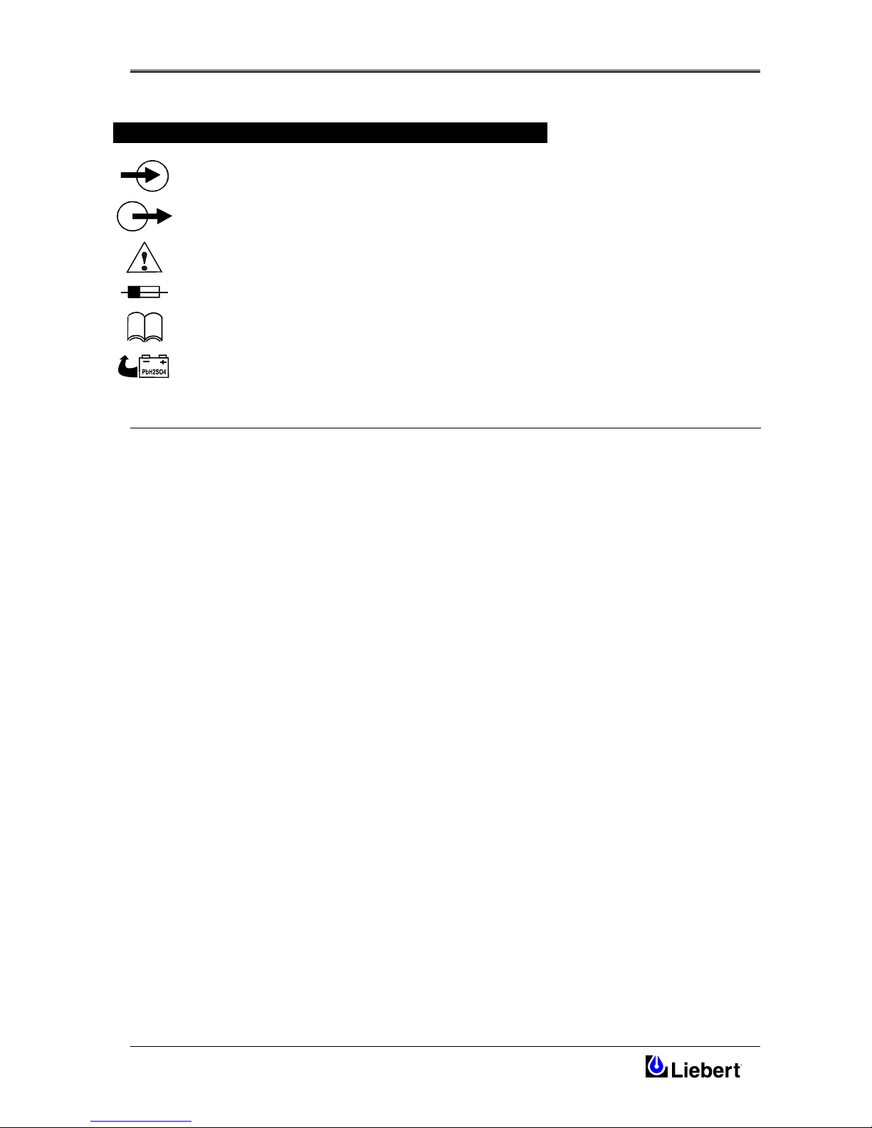
GLOSSARY OF SYMBOLS
Indicates AC Input
Indicates AC Output
Indicates Caution: Note the accompanying instruction
Indicates the position of a fuse
Requests the user to consult the manual for additional information
Indicates that the unit contains a valve regulated lead acid battery

USER MANUAL UPStation GXT 3x1
(06/02) Page vii
E
E
E
N
N
N
G
G
G
L
L
L
I
I
I
S
S
S
H
H
H
Table of Contents
1 GENERAL DESCRIPTION.........................................................................................................................................1
1.1 Introduction..............................................................................................................................................................1
1.2 Major components....................................................................................................................................................1
1.2.1 EMI/RFI filters....................................................................................................................................................1
1.2.2 Rectifier/Power Factor Correction (PFC) circuit................................................................................................2
1.2.3 Inverter.................................................................................................................................................................2
1.2.4 Battery Charger...................................................................................................................................................2
1.2.5 Battery .................................................................................................................................................................2
1.2.6 Static Bypass .......................................................................................................................................................2
1.2.7 Auto re-start.........................................................................................................................................................2
2 INSTALLATION..........................................................................................................................................................3
2.1 Installation considerations........................................................................................................................................3
2.2 Unpacking and inspection........................................................................................................................................3
2.3 Location....................................................................................................................................................................3
2.4 Electrical installation considerations........................................................................................................................4
2.4.1 Electrical Connections.........................................................................................................................................4
2.4.2 Connecting the UPS power cables......................................................................................................................5
2.4.3 Connection of optional rem ote battery cabinets..................................................................................................5
2.4.4 Stabilisers/Levelling feet.....................................................................................................................................6
2.4.5 Ferrite bead installation.......................................................................................................................................7
2.4.6 Serial Communi cation s.......................................................................................................................................7
2.4.7 SNMP Installation ( When fitted).......................................................................................................................7
2.5 Commission in g th e UPS..........................................................................................................................................8
2.5.1 Output Voltage Selector Switches.......................................................................................................................8
3 CONTROLS AND INDICATORS............................................................................................................................11
4 OPERATING MODES.............................................................................................................................................. 13
4.1 Introduction........................................................................................................................................................... 13
4.1.1 Normal mode operation- UPS mode................................................................................................................ 13
4.1.2 Battery mode operation.................................................................................................................................... 13
4.1.3 Bypass mode operation.................................................................................................................................... 14
4.1.4 Output off mode operation............................................................................................................................... 14
4.1.5 Manual operation with mains available ........................................................................................................... 14
4.1.6 Starting the UPS with m ain s av ailable............................................................................................................. 14
4.1.7 Powering down th e UPS with mains available................................................................................................ 15
4.1.8 Alternate quick powerin g down the UPS......................................................................................................... 15
4.1.9 Manual operation withou t mains...................................................................................................................... 15
4.1.10 Pow erin g u p th e UPS without mains................................................................................................................ 15
4.1.11 Pow erin g down the UPS without mains........................................................................................................... 15
4.1.12 UPS Remote shutdown option......................................................................................................................... 16
5 COMMUNICATIONS............................................................................................................................................... 17
5.1 UPS Monitoring.................................................................................................................................................... 17
5.2 UPS Intelligent Comm u n ication s.......................................................................................................................... 17
5.3 UPS Intellislot™ Communication s....................................................................................................................... 17
5.4 SNMP Web Card .................................................................................................................................................. 17
5.5 Communi cation s In terface Port............................................................................................................................. 18
6 TROUBLESHOOTING............................................................................................................................................. 19
6.1 Audible Alarm Con ditions.................................................................................................................................... 20
6.2 Troubleshooting guide...........................................................................................................................................20
6.3 Maintenance .......................................................................................................................................................... 21

UPStation GXT 3x1 USER MANUAL
Page viii (06/02)
7 SPECIFICATIONS.................................................................................................................................................... 23
7.1 Limited Warranty................................................................................................................................................. 24
UPStation GXT 3x1 Chapter 1 – Gene r al D escription
Design Concept
(06/02) Page 1
1 GENERAL DESCRIPTION
1.1 Introduction
Congratulations on your choice of the UPStation GXT™ Uninterruptible Power System (UPS). It provides conditioned
power to microcomputers and other sensitive electronic equipm en t.
Upon generation, AC power is clean and stable. However, during transmission and distribution it may be subject to
voltage sags, spikes, or complete power failure, which may interrupt computer operations, cause data loss, or even
damage equipmen t. The UPStation GXT protects equipment from these disturban ces .
The UPStation GXT is an “on-line” UPS that continuously conditions and regulates its output voltage, whether the
mains power is present or not. It supplies connected equipment with clean sinewave power. Sensitive electronic
equipment operates best from sinewave power. The GXT 3x1 -230X models have an additional output isolation
transformer.
For ease of use, the UPStation GXT contains a light emitting diode (LED) display to indicate either “load percentage” or
“battery capacity” depending upon the mode of operation. It also provides self-diagnostics, a combination On/Alarm
Silence/Manual Battery Test button, a combination Off/Bypass button, and two levels of alarms when the unit is
operating on battery .
The UPStation GXT has an interface port for communications between the UPS and a LAN server or other computer
system. This port provides detailed operating information including voltages, currents, and alarm status to the host
system when used in conjunction with the SiteNet® 2 software. SiteNet® 2 software can also remotely control UPS
operation.
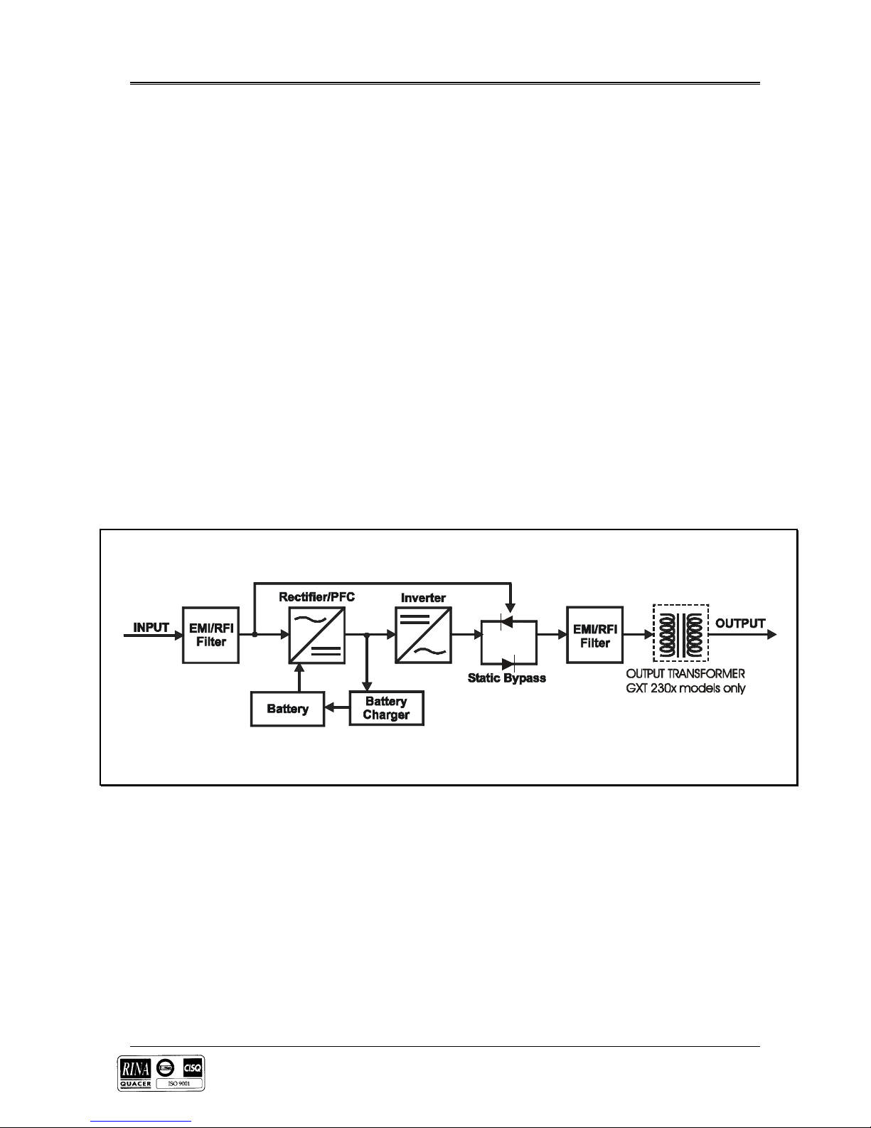
1.2 Major components
Figure 1-1
1.2.1 EMI/RFI filters
These UPS components provide surge protection, and filter both electromagnetic interference (EMI) and radio
frequency interference (RFI). They minimize any surges or interference present in the mains line and keep the sensitive
equipment protected.

Chapter 1 – Gene r al D escription UPStation G X T 3x1
Design Concept
Page 2 (06/02)
1.2.2 Rectifier/Power Factor Correction (PFC) circuit
In normal operation, the rectifier/power factor correction (PFC) circuit converts m ain s AC power to regulated DC power
for use by the inverter, while ensuring that the wave shape of the input current used by the UPS is near ideal. Extracting
this sinewave input current achieves two objectives: the mains power is used as efficiently as possible by the UPS, and
the amount of distortion ref l ected on the mains is reduced. This results in cleaner power being available to other devices
in the building not being protected by the UPStation GXT.
1.2.3 Inverter
In normal operation, the inverter utilises the DC output of the power factor correction circuit and “inverts” it into
precise, regulated sinewave AC power. Upon a mains power failure, the inverter receives its required energy from the
battery through the rectifier / PFC. In both modes of the operation, the UPS inverter is on-line and continuously
generating clean, precise, regu lated AC output power.
1.2.4 Battery Charger
The battery charger utilises energy from the Rectifier / PFC and precisely regulates it to continuously “float” charge the
battery system . The battery system charges whenever the UPStation GXT is connected to main s power.
1.2.5 Battery
The UPStation GXT employs valve regulated, non-spillable, lead acid batteries. At typical room temperatures and w ith
the UPS float charging, the battery system will last many years. Optional external battery cabin ets are available to
provide extended run times.
1.2.6 Static Bypass
The UPStation GXT provides an alternate path for mains power to the connected load, in the unlikely event of a UPS
malfunction. Should the UPS have an overload, over temperature, or UPS failure condition, the UPS automatically
transfers the connected load to BYPASS providing the bypass voltage is within specification. BYPASS operation is
indicated by an alarm and an illuminated BYPASS LED (other LED’s may be illuminated to indicate the diagnosed
problem). To manually transfer the connected load from the inverter to BYPASS power, press the output OFF button
once.
NOTE: The BYPASS power path does NOT protect the connected equipment from disturbances on the mains supply
and its range of operation is limited to +/- 15% of the nominal input supply voltage.
1.2.7 Auto re-start
Upon restoration of the mains AC power after a mains power outage and complete battery discharge, the UPS will
automatically restart and s u pply power to the critical load and the battery ch arg er au tomatically recharges the battery.
 Loading...