

Page 1
Large Systems
iCOM
Environmental Training and Service Manual
Microprocessor
TM-10098: Rev. 02/06
Page 2

Training & Service
iCOM
Control Training and Service Manual
iCOM
Manual
1
Page 3

iCOM
Controls Training and Service Manual
Disclaimer of Warranties and Limitations of Liabilities
The authors and editors have taken every precaution to ensure accuracy and completeness
in this manual. The authors and editors make no expressed or implied warranty of any
kind with regard to the documentation in this manual. Liebert Corporation assumes no
responsibility, and disclaims all liability for incidental or consequential damages resulting
from the use of this information or from errors or omissions. Liebert Corporation may
make improvements and/or changes in the product(s) described in this manual at any time.
Information in this manual is subject to change at any time and does not represent a
commitment on the part of Liebert Corporation.
Liebert® and the Liebert logo are registered trademarks of Liebert Corporation.
Emerson® and the Emerson logo are registered trademarks of Emerson Electric Co.
Copyright © 2004 by Liebert Corporation
All rights reserved throughout the world.
Specifications subject to change without notice.
Printed in the United States of America
2
Page 4

iCOM
Control Training and Service Manual
Table of Contents
Chapter 1: Temperature/ Humidity Control 6
Temperature Control Types
Intelligent Control
Proportional Control
Proportional + Integral (PI) Control
Proportional + Integral + Derivative (PID) Control
Temperature Control
Operations and Charts
2 Stage Compressorized
4 Stage Compressorized Cooling
Dual Compressor Digital Scroll Operation
Glycool Cooling
Dual Source Cooling
Staged Reheat
Humidity Control
Absolute (Predictive) Humidity Control
Relative Humidity Control
Humidifier Operation
Autoflush Control for Infrared
Dehumidification Operation
1 Stage Dehumidification, Compressorized Operation
2 Stage Dehumidification, Compressorized Operation
Reheat During Dehumidification
Additional Programs
Next Maintenance Calculation
Shared Parameters an Understanding
Networking and Functions
Teamwork
Unit Lead/ Lag or Running/ Standby Fuctions
6
6
8
8
9
11
11
11
13
18
18
20
21
25
25
27
27
29
31
31
32
33
35
38
40
41
48
49
3
Page 5

iCOM
Controls Training and Service Manual
Chapter 2: Programming Functions 52
Programming Functions
iCOM Display Components and Functions
iCOM Keypad Layout Descriptions
iCOM Display Symbols/ Icons
Programming Functions
Status Display Screens
Menu Screens – Icons/ Parameter Names
User Menu Icons and Descriptions
Service Menu Icons and Descriptions
Advanced Menu Icons and Descriptions
User Menu Parameters
Service Menu Parameters
Advanced Menu Parameters
Event Notifications Parameters
Event ID Number, Description and Function
52
53
54
55
56
56
57
58
59
60
60
67
84
90
92
Chapter 3: iCOM Hardware Connections 100
Introduction
Display Boards
Unit Control Board Switches and Jumpers
Large Display Switches and Jumpers
Small Display Switches and Jumpers
Temperature/ Humidity Board Switches and Jumpers
Unit Control Board Plug Connectors
Fuse Board Connectors
Temperature/ Humidity Board Connectors
100
101
102
104
105
106
107
111
112
Chapter 4: General Troubleshooting Data 114
Introduction
Isolation
Basic Operation of the Triac
Basic Operation of the Opto-Isolator
Troubleshooting the Opto-Isolator
114
115
116
118
119
4
Page 6

iCOM
Control Training and Service Manual
Unit Control Board: Opto-Isolator/ Triac Legends
iCOM Diagnostics/ Service Mode Programs
Basic Troubleshooting Steps
Moisture Content Charts
Suction Transducer Information
Digital Scroll High Temperature Sensor Chart
Unit Code Description
Troubleshooting Checklist
Glossary of Unit/ Systems Parameters
121
123
124
126
143
144
145
146
147
Glossary of Terms 156
Computer and Network Terms 160
Network Information 165
How To Use The Schematics 169
Electrical Schematics 170
5
Page 7

iCOM
Controls Training and Service Manual
Chapter 1
Temperature and Humidity
Control Programs
This section provides details on how your Liebert iCOM control responds to the
user programmed inputs values and room conditions. Refer to this section when
you need specific information control operation. This section includes details on
four (4) user selectable temperature control programs and two (2) user selectable
and humidity control programs.
Cooling and/ or Heating Required, in Percent (%)
The temperature control programs for the iCOM microprocessor is based on a
calculated percent (%) requirement for cooling and/ or heating. This percent (%)
requirement is determined by the control type (algorithm) selected by the user.
The four (4) user selectable temperature control programs are:
• Intelligent
• Proportional (P)
• Proportional + Integral (PI)
• Proportional + Integral + Derivative (PID)
Temperature Control Program Types
Intelligent Control – Factory Default Setting
The Intelligent Control operates from a set of general rules that defines how the
control output should be adjusted for different system conditions. The rules are
designed to duplicate the actions that an experienced human operator would take
if manually controlling the system.
Basically, this is done in a three-function process that differs from earlier
mathematically defined strict type data, hence, fuzzy logic. The on and off, true or
6
Page 8

iCOM
untrue type of statement is not used. The consideration now is how to set the
input value into a membership set, qualify this membership with rules, then decide
on the output consequence for action. It is not really that simple, but it is basically
how it works. The process:
Membership
• Measure value of input variables
• Map and transfer data into range of set domain
• Assign input membership into sets
Knowledge Base/Decision Making
• Provide a data base of definitions for rules base
• Provide a rules base and define function and domain
• Simulate human decision making based on concepts and actions
defined by implications and rules
Control Training and Service Manual
Consequence
• Convert defined range of knowledge to a corresponding output
variable
• Define a non-intelligent action from a deduced intelligent action
Just as an operator might take several things into consideration before making a
temperature control decision, the intelligent control can be programmed to do
likewise. For example, not only is the current temperature used in making
temperature control decisions, but also conditions such as:
• How fast is the temperature changing?
• What direction is the temperature changing?
• What is the cooling output now?
• What was the cooling output in the past?
• How long ago was the cooling output changed?
• Other factors
Any number of rules can be used in an intelligent control to define the controls
operation under various operating conditions. Hence, several advantages are
gained from this type of control over a more standard control approach that uses a
fixed mathematical equation to define the operation of the control for all conditions
(such as a Proportional or PID Control). You can expect Intelligent Control to be
7
Page 9

iCOM
more efficient and precise for most applications, but system performance based on
room conditions is not as predictable as standard approaches that use a fixed
equation.
The Liebert Intelligent Control includes rules that significantly enhance the
performance of the system, both from a standpoint of precision control and system
reliability.
Rules are included that:
Controls Training and Service Manual
• Cause the control to ignore very small or temporary temperature/
humidity deviations. This eliminates unnecessary control adjustments
that contribute to control instability.
• Help limit the frequency of control adjustments thus extending the life of
system components that are susceptible to mechanical wear or cycling.
• Recognize undesired modes of control operation such as hunting, and
make adjustments to the control response to eliminate them.
• Estimate the present load on the system and then tend to force the
control output to the appropriate state.
• Recognizes conditions, which indicate a large load change and allows
the control to temporarily respond more quickly than normal.
• Cause the control to anticipate the need for reheat during
dehumidification and activates reheats when overcooling occurs.
Proportional (P) Control
The proportional control is the standard control method that maintains the room at
a temperature proportional to the load. The temperature maintained increases as
the room load increases. At full load the room would be controlled at a
temperature equal to the temperature set point (TSP) plus ½ of the temperature
proportional band (PB). The operator programmed inputs are the temperature set
point (TSP) and temperature proportional band (PB) adjustments. The operator
may also program a temperature dead band (DB) adjustment.
Proportional + Integral (PI) Control
The PI control combines two (2) individual terms to determine the control output
for a given set of conditions. Note that PI control is used only for temperature. If
PI control is selected, the humidity control will be in percent relative humidity
(%RH).
The proportional (P) term is determined by the difference between the current
temperature and the control set point. This term is expressed in % cooling
(heating desired for each degree above (below) the set point. It is adjustable from
0% to 100% per degree. The purpose of this term is to adjust the control output
for any deviation between the current temperature and the control set point.
8
Page 10

iCOM
The integral (I) term is determined by two things: the difference between the return
air temperature and control set point and the amount of time this difference has
existed. This term is expressed in % cooling (heating) desired for each minute
and degree above (below) the set point. It is adjustable from 0% - 100% per
degree/minute. The purpose of this term is to force the control to maintain the
temperature around the set point by slowly but continuously adding (subtracting) a
small amount of cooling (heating) to the total control output until the temperature is
at the set point.
Control Training and Service Manual
Proportional + Integral + Derivative (PID) Control
The PID control combines three (3) individual terms to determine the control
output for a given set of conditions. Note that PID control is used only for
temperature. If PID control is selected, the humidity control will be in percent
relative humidity (%RH).
The proportional (P) term is determined by the difference between the current
temperature and the control set point. This term is expressed in % cooling
(heating desired for each degree above (below) the set point. It is adjustable from
0% to 100% per degree. The purpose of this term is to adjust the control output
for any deviation between the current temperature and the control set point.
The integral (I) term is determined by two things: the difference between the return
air temperature and control set point and the amount of time this difference has
existed. This term is expressed in % cooling (heating) desired for each minute
and degree above (below) the set point. It is adjustable from 0% - 100% per
degree/minute. The purpose of this term is to force the control to maintain the
temperature around the set point by slowly but continuously adding (subtracting) a
small amount of cooling (heating) to the total control output until the temperature is
at the set point.
The derivative (D) term is determined by the rate of change of temperature. This
term is expressed in % cooling (heating) desired for each degree per minute rise
(fall) in temperature. It is adjustable from 0% to 100% per degree/minute. The
purpose of this term is to adjust the control output for quickly changing
temperatures, thus providing an anticipation control.
All three terms are adjusted by selecting the “Setpoints” icon in either the USER or
SERVICE Menu screen. If PID control is selected, the temperature proportional
band value (and optional temperature dead band value) is not used by the control.
For optimum performance, a PID control must be adjusted or tuned according to
the characteristics of the particular space and load to be controlled. Improper
tuning can cause the control to exhibit poor response and/ or hunting. The
characteristics of the space and load may change seasonally, so occasional
returning is required for optimum performance.
9
Page 11

iCOM
A suggested tuning procedure is as follows:
Controls Training and Service Manual
1. Initially adjust the integral and derivative settings to 0% / degree-min
and 0% / degree / min..
2. Starting with 20% / degree, adjust the proportional setting in small
increments (10% steps) until the control sustains a constant hunting
action (the temperature swings are approximately the same amplitude
from one peak to the next).
3. Note the time in minutes between peaks of adjacent temperature
swings and the amplitude of the temperature swing (degrees above the
set point).
4. Adjust the proportional control setting to about l/2 the value obtained in
Step 2.
5. Adjust the integral setting to a value calculated by the following
equation: approximate room load (in % full load) time between
peaks x peak amplitude x 4.
Note: If calculation results in a value of less than 1%, then set the
integral to 1%.
6. Adjust the derivative to a value calculated by the following equation:
time between peaks x 5%.
The above tuning procedure is only an approximation for an initial set of
adjustments and are based on the "average" room characteristics. Your particular
settings may need to be further adjusted for optimum PID control performance.
Some suggestions for additional tuning are as follows:
• If cooling output overshoot is occurring on load changes, decrease
the proportional setting or the derivative setting.
• If system hunting occurs with constant room load, decrease the
integral setting.
• If the control responds too slowly, resulting in large temperature
excursions on a load change, increase the proportional setting or
the derivative setting.
• If a constant temperature deviation exists between the
temperature and set point, increase the integral setting.
10
Page 12

iCOM
Control Training and Service Manual
Temperature Control
Operations and Charts
The temperature proportional control band value is divided into two parts: the
temperature set point plus ½ of the temperature proportional band for cooling
operation and the temperature set point minus ½ of the temperature proportional
band for heating operation. A temperature dead band can also be programmed
into the control to shift the cooling and/ or heating on/ off operations away from the
temperature set point.
This programmed temperature dead band value is divided into two parts: the
temperature set point plus ½ of the dead band – no cooling operation and the
temperature set point minus ½ of the band – no heating operation.
The temperature set point range is adjustable from 41 - 104°F in increments of
1°F. The temperature proportional band range is adjustable from 2 - 54°F in
increments of 1°F. The temperature dead band range is adjustable from 0 - 36°F
in increments of 1°F.
Standard 2 Stage Compressorized Cooling
The basic temperature cooling control band is established at the temperature set
point with the length equal to ½ of the programmed temperature proportional band
divided by the number of cooling stages.
The Liebert DS units are supplied with two (2) compressors, each compressor is
rated at ½ of the unit capacity. The two (2) compressors will be either the
semi-hermetic or scroll type and will operate in an on/ off configuration to cool the
space.
The temperature controller activates the first cooling stage (lead compressor)
when the return air temperature increases to 50% of the cooling proportional band
and the second cooling stage (lag compressor) at 100% of the cooling proportional
band. The optional hot gas bypass solenoid valve, supplied with each compressor
when ordered, is also energized on a call for cooling.
11
Page 13
iCOM
The temperature controller deactivates the second stage of cooling (lag
compressor) when the return air temperature decreases to 50% of the cooling
proportional control band value. The first cooling stage (lead compressor) is
deactivated when the return air temperature decreases to the temperature set
point value or 0% of the cooling proportional control band value.
Controls Training and Service Manual
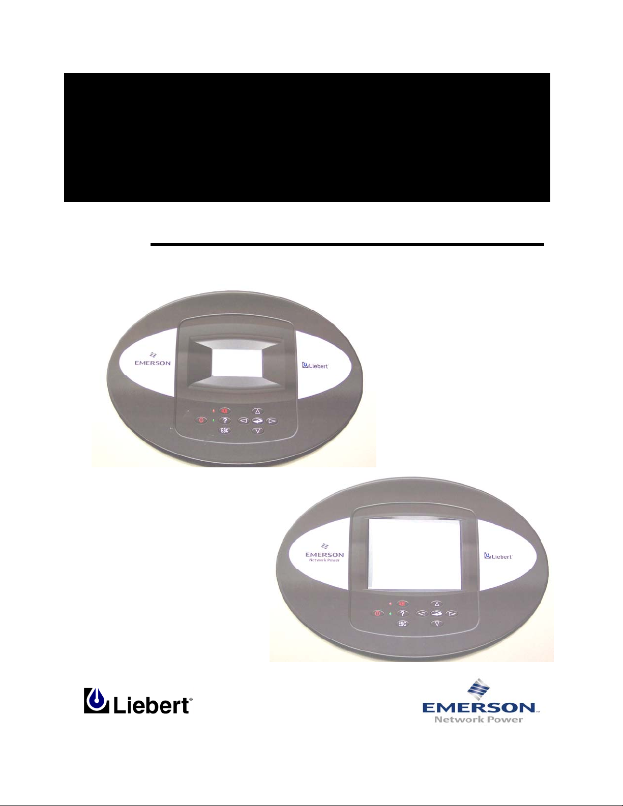
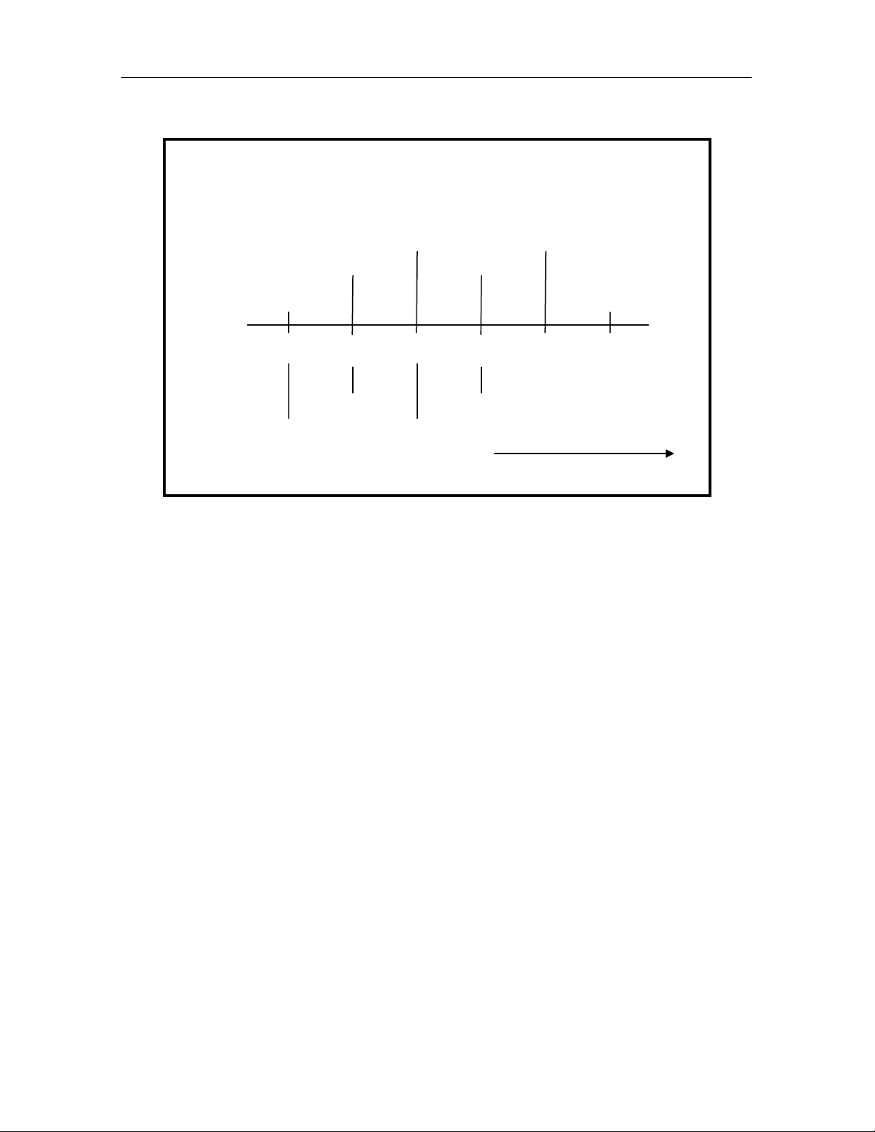
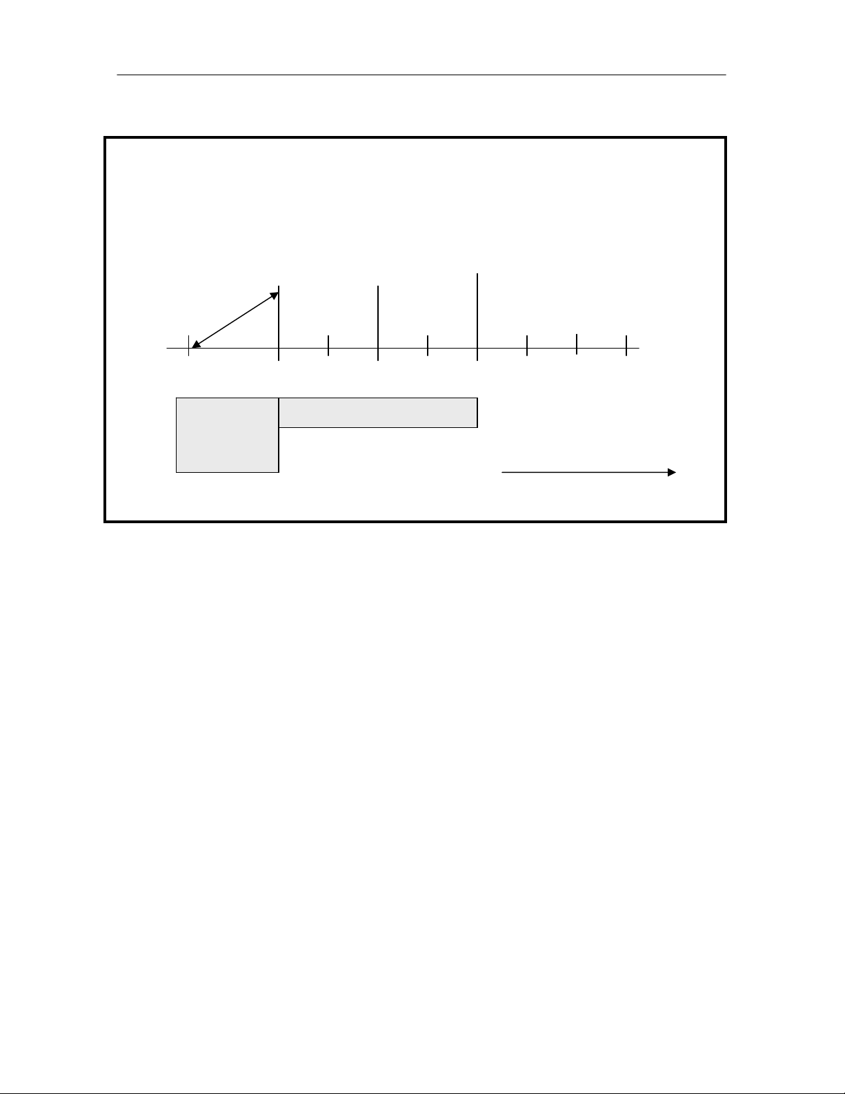
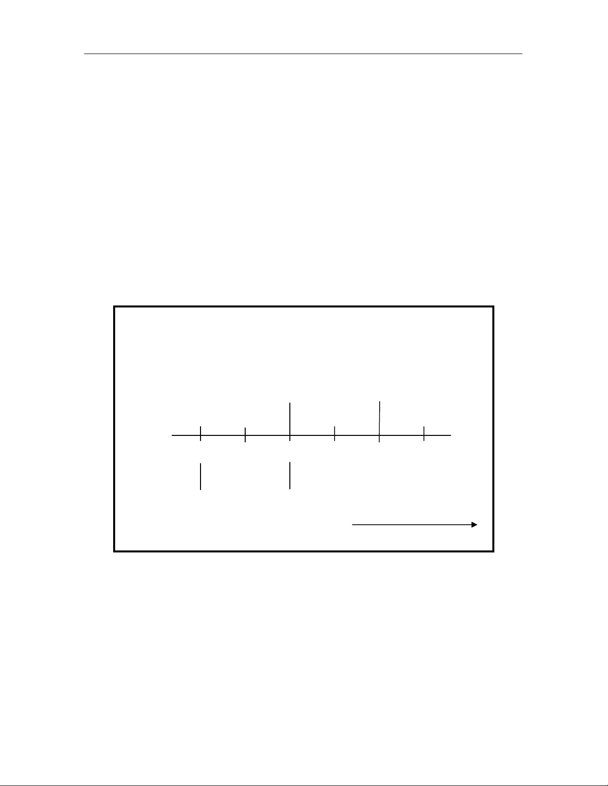
2 Stage Compressorized Cooling – No Dead Band
Note: in the above example that the control band begins at the 70°F temperature
set point and has a length of 4°F, which is ½ of the programmed temperature
proportional band value.
As the return air temperature increases Cooling 1 (lead compressor) is activated at
72°F or 50% of the cooling control band. If the return air temperature continues to
increase Cooling 2 (lag compressor) will activate at 74°F or 100% of the cooling
control band.
When the return air temperature starts to decrease, Cooling 2 (lag compressor) is
deactivated at 72°F or 50% of the cooling control band and Cooling 1 (lead
compressor) is deactivated at the temperature set point of 70°F or 0% of the
cooling control band.
Temp Set Point: 70°F
Proportional Band: 8°F
Temp Set Point + (1/2 Proportional Band)
Cool 1 On
70 71 72 73 74 75
Cool 1 Off
Cool 2 Off
Cool 2 On
Increasing Temperature
12
Page 14
iCOM
Control Training and Service Manual
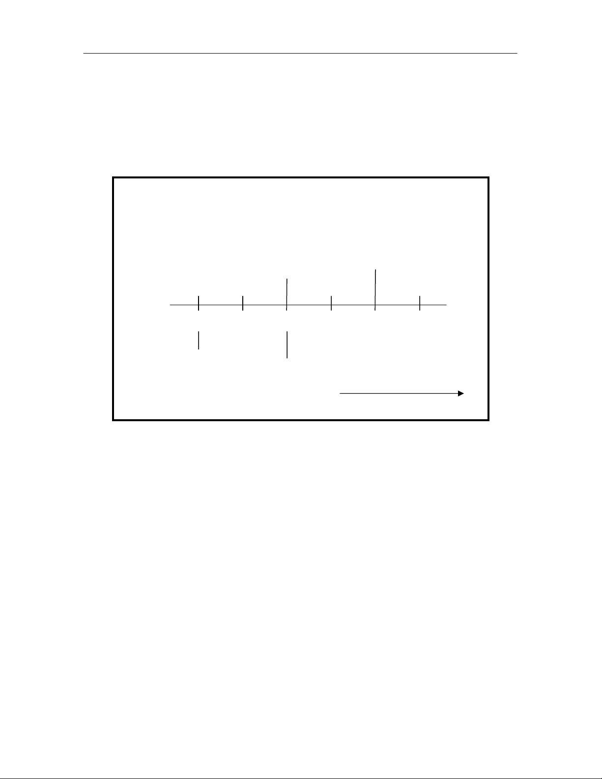
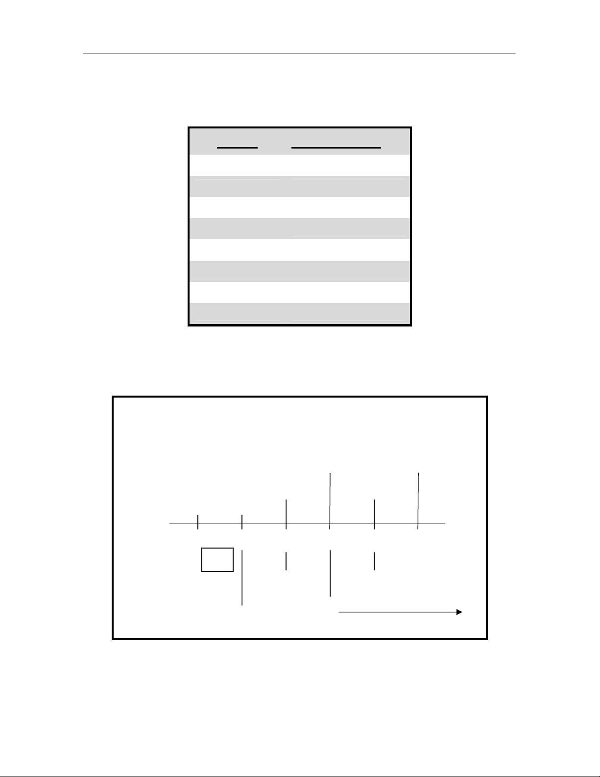
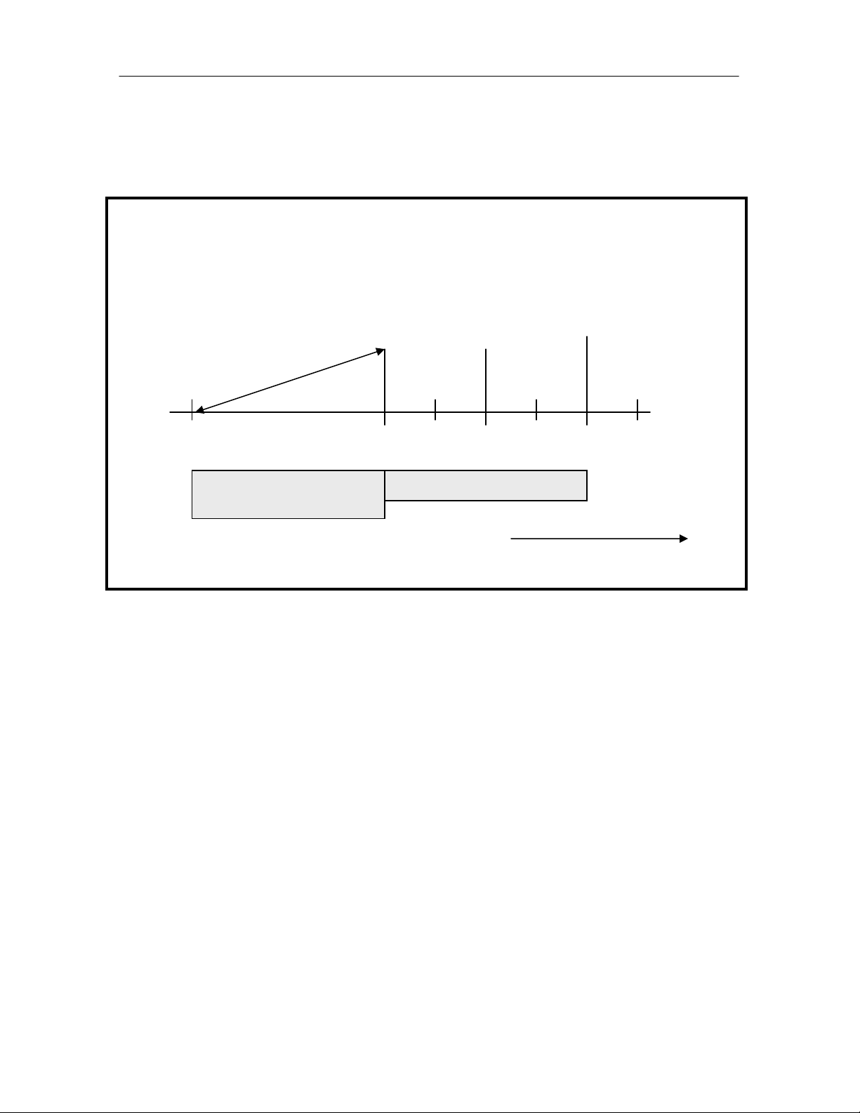
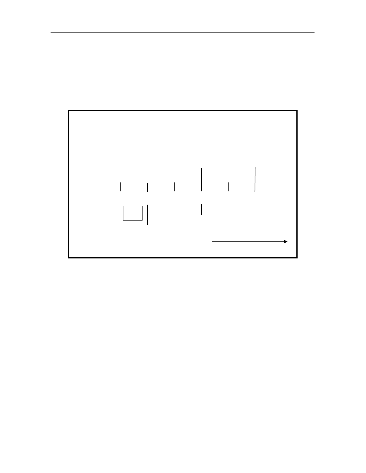
2 Stage Compressorized Cooling – With Dead Band
Note: in the above example that the control band begins at the 70°F temperature
set point and has a length of 5°F, which is ½ of the programmed temperature dead
band value plus ½ of the programmed temperature proportional band value.
As the return air temperature increases Cooling 1 (lead compressor) is activated at
73°F or ½ of the dead band value plus 50% of the cooling control band. If the
return air temperature continues to increase Cooling 2 (lag compressor) will
activate at 75°F or ½ of the dead band value plus 100% of the cooling control
band.
When the return air temperature starts to decrease, Cooling 2 (lag compressor) is
deactivated at 73°F or ½ of the dead band value plus 50% of the cooling control
band and Cooling 1 (lead compressor) is deactivated at 71°F or ½ of the dead
band value plus 0% of the cooling control band.
Remember the temperature dead band value is used by the control to shift the
cooling on/ off operations away from the temperature set point.
Temp Set Point + (1/2 Dead Band + 1/2 Proportional Band)
Temp Set Point: 70°F
Proportional Band: 8°F
Dead Band: 2°F
Cool 1 On
70 71 72 73 74 75
DB
Cool 1 Off
Cool 2 Off
Increasing Temperature
Cool 2 On
Optional 4 - Stage Cooling, Two (2) Compressors with Unloaders
The basic temperature cooling control band is established at the temperature set
point with the length equal to ½ of the programmed temperature proportional band
divided by the number of cooling stages.
The Liebert DS units are supplied with two (2) compressors, each compressor is
rated at ½ of the unit capacity. Each compressor will be the semi-hermetic type
13
Page 15
iCOM
and will be supplied with an electrical cylinder unloader valve. The electrical
solenoid valve used to unload or reduce the cooling capacity of the compressor.
The compressors will operate in an on/ off - loaded/ unloaded configuration
method to cool the space. The hot gas bypass solenoid valve option is not
available on 4 stage systems.
The temperature controller activates the first cooling stage, lead compressor
unloaded, when the return air temperature increases to 25% of the cooling
proportional band. The second cooling stage, lag compressor unloaded, is
activated when the return air temperature increases to 50% of the cooling
proportional band.
The temperature controller activates the third cooling stage, the lead compressor
loaded, when the return air temperature increases to 75% of the cooling
proportional band. The fourth cooling stage, the lag compressor loaded, is
activated when the return air temperature increases to 100% of the cooling
proportional band.
The temperature controller deactivates the fourth cooling stage, lag compressor
loaded, when the return air temperature decreases to 75% of the cooling
proportional control band value. The third cooling stage, lead compressor loaded,
is deactivated when the return air temperature decreases to 50% of the cooling
proportional control band value.
The temperature controller deactivates the second cooling stage, lag compressor
unloaded, when the return air temperature decreases to 25% of the cooling
proportional control band value. The first cooling stage, lead compressor
unloaded, is deactivated when the return air temperature decreases to the
temperature set point value or 0% of the cooling proportional control band value.
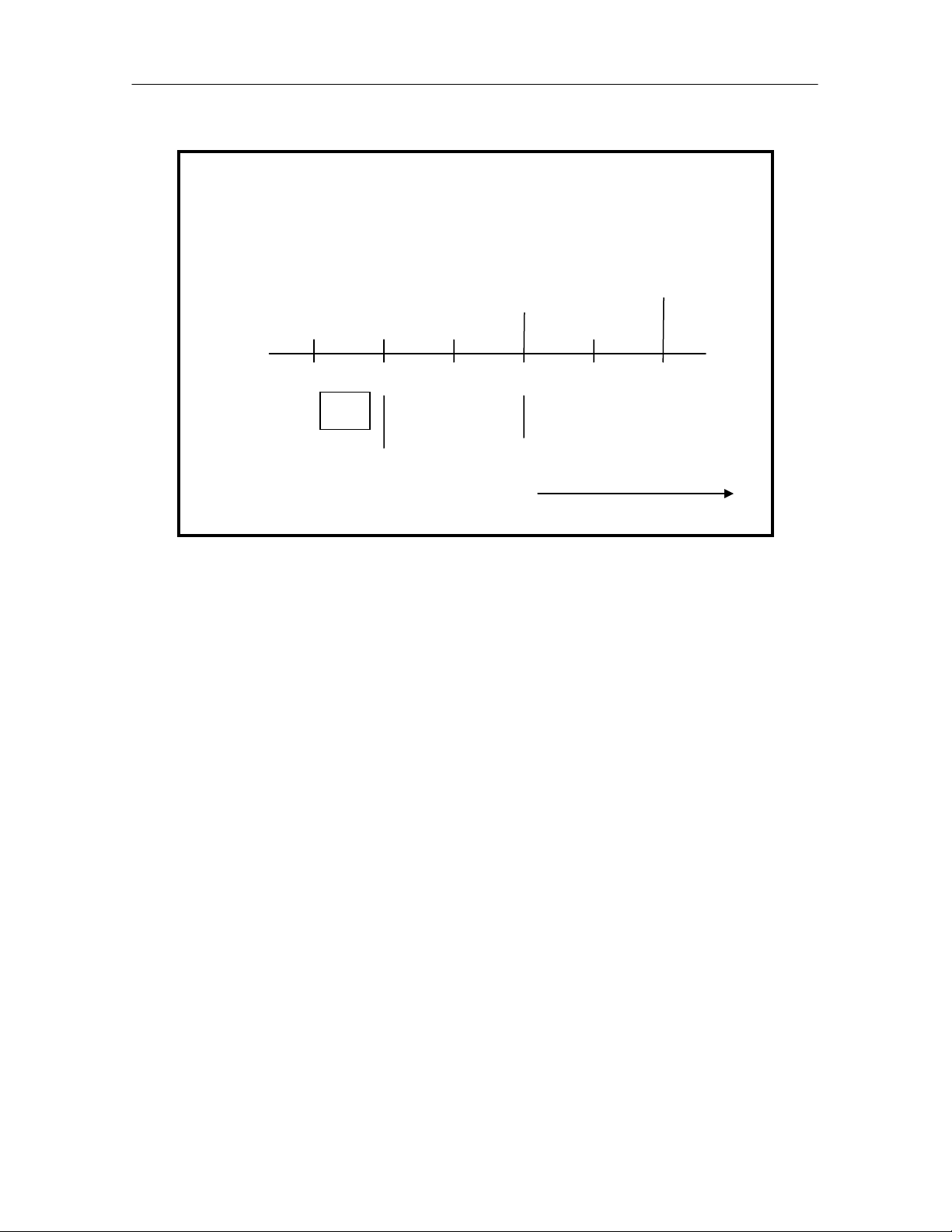
The table below shows the devices activated by each of the four cooling stages.
Controls Training and Service Manual
STAGE COMPRESSORS, UNLOADER STATE
1
2
3
4
Compressor 1 On, Unloader On (Energized)
Compressor 2 Off, Unloader Off (De-Energized)
Compressor 1 On, Unloader On (Energized)
Compressor 2 Off, Unloader On (Energized)
Compressor 1 On, Unloader Off (De-Energized)
Compressor 2 On, Unloader On (Energized)
Compressor 1 On, Unloader Off (De-Energized)
Compressor 2 On, Unloader Off (De-Energized)
14
Page 16
iCOM
Control Training and Service Manual
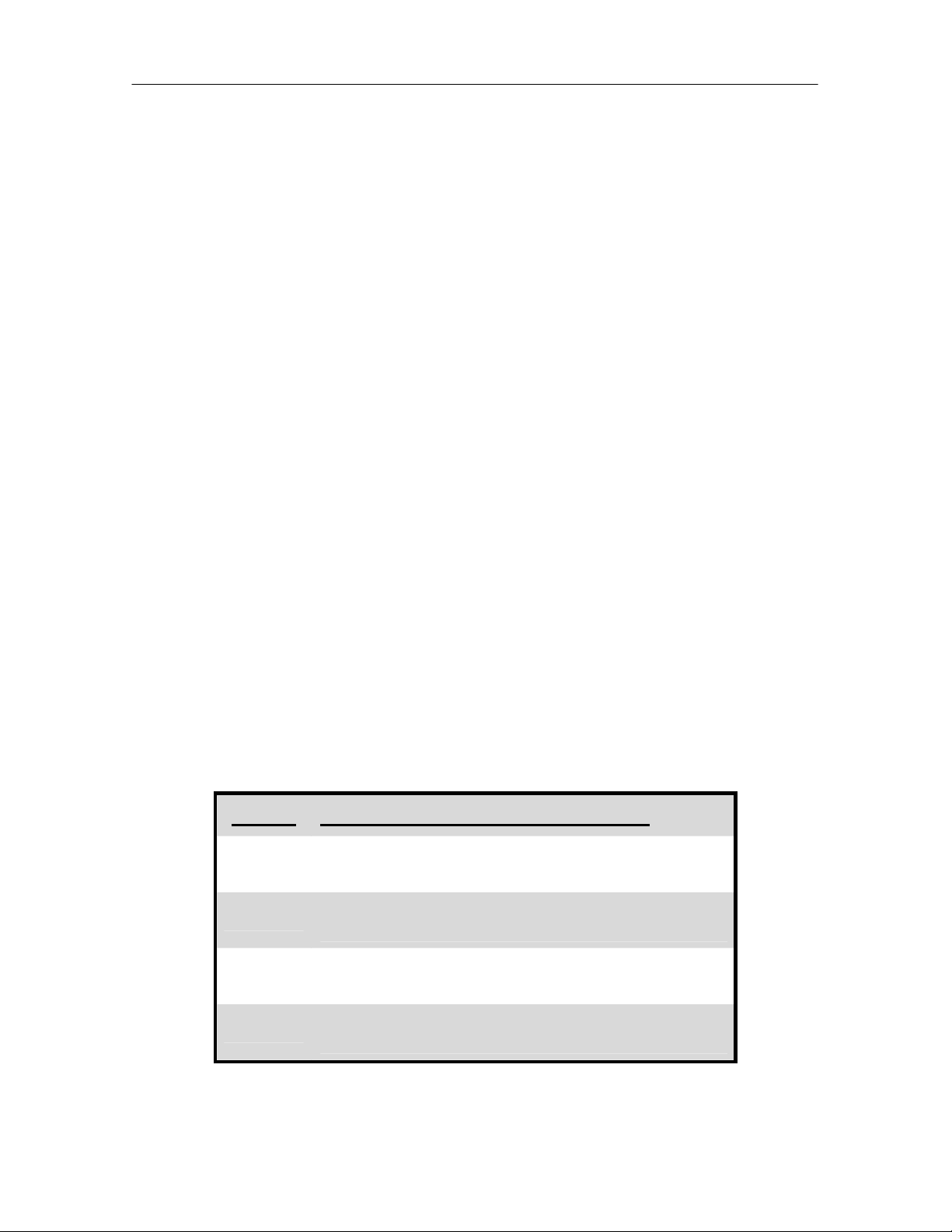
4 Stage Compressorized Cooling – No Dead Band
Note: in the above example that the control band begins at the 70°F temperature
set point and has a length of 4°F, which is ½ of the programmed temperature
proportional band value.
As the return air temperature increases Cooling 1, the lead compressor unloaded,
is activated at 71°F or 25% of the cooling control band. If the return air
temperature continues to increase Cooling 2, the lag compressor unloaded is
activated at 72°F or 50% of the cooling control band. If the return air temperature
continues to increase Cooling 3, the lead compressor is loaded at 73°F or 75% of
the cooling control band. If the return air temperature continues to increase
Cooling 4, the lag compressor is loaded at 74°F or 100% of the cooling control
band.
When the return air temperature starts to decrease, Cooling 4 is deactivated at
73°F or 75% of the cooling control band. If the return air temperature continues to
decrease Cooling 3 is deactivate at 72°F or 50% of the cooling control band. If the
return air temperature continues to decrease Cooling 2 is deactivate at 71°F or
25% of the cooling control band and Cooling 1 is deactivated at the temperature
set point of 70°F or 0% of the cooling control band.
Temp Set Point: 70°F
Proportional Band: 8°F
Temp Set Point + (1/2 Proportional Band)
Cool 2 On
Cool 1 On
70 71 72 73 74 75
Cool 1 Off
Cool 3 Off
Cool 3 On
Cool 4 OffCool 2 Off
Cool 4 On
Increasing Temperature
15
Page 17
iCOM
The example below is based on a temperature set point of 70°F with a control
band length of 4°F, which is ½ of the programmed temperature proportional band
value.
Controls Training and Service Manual
STAGE TEMPERATURE
Cool 1 ON
Cool 2 ON
Cool 3 ON
Cool 4 ON
Cool 4 OFF
Cool 3 OFF
Cool 2 OFF
Cool 1 OFF Set point
Set point plus 1°F
Set point plus 2°F
Set point plus 3°F
Set point plus 4°F
Set point plus 3°F
Set point plus 2°F
Set point plus 1°F
4 Stage Compressorized Cooling – With Dead Band
Note: in the above example that the control band begins at the 70°F temperature
set point and has a length of 5°F, which is ½ of the programmed temperature dead
band value plus ½ of the programmed temperature proportional band value.
Temp Set Point + (1/2 Dead Band + 1/2 Proportional Band)
Temp Set Point: 70°F
Proportional Band: 8°F
Dead Band: 2°F
70 71 72 73 74 75
DB
Cool 1 Off
Cool 2 On
Cool 1 On Cool 3 On
Cool 2 Off
Cool 3 Off
Cool 4 Off
Increasing Temperature
Cool 4 On
16
Page 18

iCOM
As the return air temperature increases Cooling 1, lead compressor unloaded, is
activated at 72°F or ½ of the dead band value plus 25% of the cooling control
band. If the return air temperature continues to increase Cooling 2, lag
compressor unloaded, will activate at 73°F or ½ of the dead band value plus 50%
of the cooling control band. If the return air temperature continues to increase
Cooling 3, lead compressor unloaded, is activated at 74°F or ½ of the dead band
value plus 75% of the cooling control band. If the return air temperature continues
to increase Cooling 4, lag compressor loaded, will activate at 75°F or ½ of the
dead band value plus 100% of the cooling control band.
When the return air temperature starts to decrease, Cooling 4 is deactivated at
74°F or ½ of the dead band value plus 75% of the cooling control band. If the
return air temperature continues to decrease Cooling 3 will be deactivate at 73°F
or ½ of the dead band value plus 50% of the cooling control band. If the return air
temperature continues to decrease Cooling 2 will be deactivate at 72°F or ½ of the
dead band value plus 25% of the cooling control band and Cooling 1 is
deactivated at 71°F or 1/2 the dead band value plus 0% of the cooling control
band.
Remember the temperature dead band value is used by the control to shift the
cooling on/ off operations away from the temperature set point.
Control Training and Service Manual
17
Page 19
iCOM
p
f
p
d
Controls Training and Service Manual
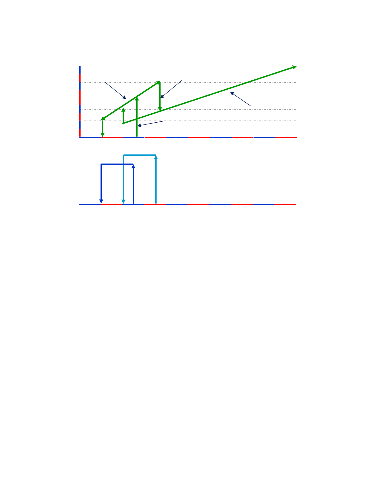
Optional Dual Compressor Digital Scroll Operation
100
1 compressor operation
Switch 2
n
70
50
PWM
35
20
st
2 compressor operation
ressor ONSwitch 1 com
Off
Of
C1
On
C2
On
Start/ sto
10
20
25
35 700%
In the chart above we are defining the Digital Compressor start and stop at the
capacity need and how the compressors load and unload with the PWM from the
controller and the unit setting for temperature control.
Note that the Digital Scroll will run continuously while the head is raised and
lowered as the need for cooling is required from 10% to 100% and vise versa.
Optional Glycool (Econ-O-Cycle) Cooling
When supplied with the Glycool option, the basic unit is supplied with an additional
coil, piping, valve and a Glycol Fluid Sensor (AQ), which is mounted to the unit
supply fluid line and serves as control interface in determining the system
operation. Selection of the glycool or compressorized operation is controlled by
microprocessor using this aquastat to sense the glycol temperature.
The Glycool (Econ-O-Cycle) Cooling program establishes two distinct control
bands for cooling control operation. The first band controls the operation of the
chilled glycol valve and the second controls the operation of the compressors,
either 2-stage or 4-stage.
The microprocessor checks the return air temperature and the entering glycol fluid
temperature to determine a cooling capacity. In order to reduce compressor
cycling and to prevent chilled glycol valve hunting, Glycool (Econ-o-Cycle) cooling
capacity does not become available until the entering chilled glycol fluid
18
Page 20
iCOM
Control Training and Service Manual
temperature is at least 8°F below the return air temperature, or 3°F lower than the
return air temperature for two consecutive hours.
When the microprocessor decides that the return glycol fluid temperature is cold
enough the first cooling band is the modulating valve control method, and the
second band, added to the first band, is for the compressors as in the normal
2-Stage or 4-Stage control method. If the chilled glycol fluid temperature is not
cold enough the valve control band is replaced by the compressor band. If the
chilled glycol cooling capacity is reduced by a rise in the glycol fluid temperature,
the control band shrinks proportionally. This allows the compressor band to move
down as well. The following shows the Glycool operation at 100% capacity and
the Glycool at 50% capacity.
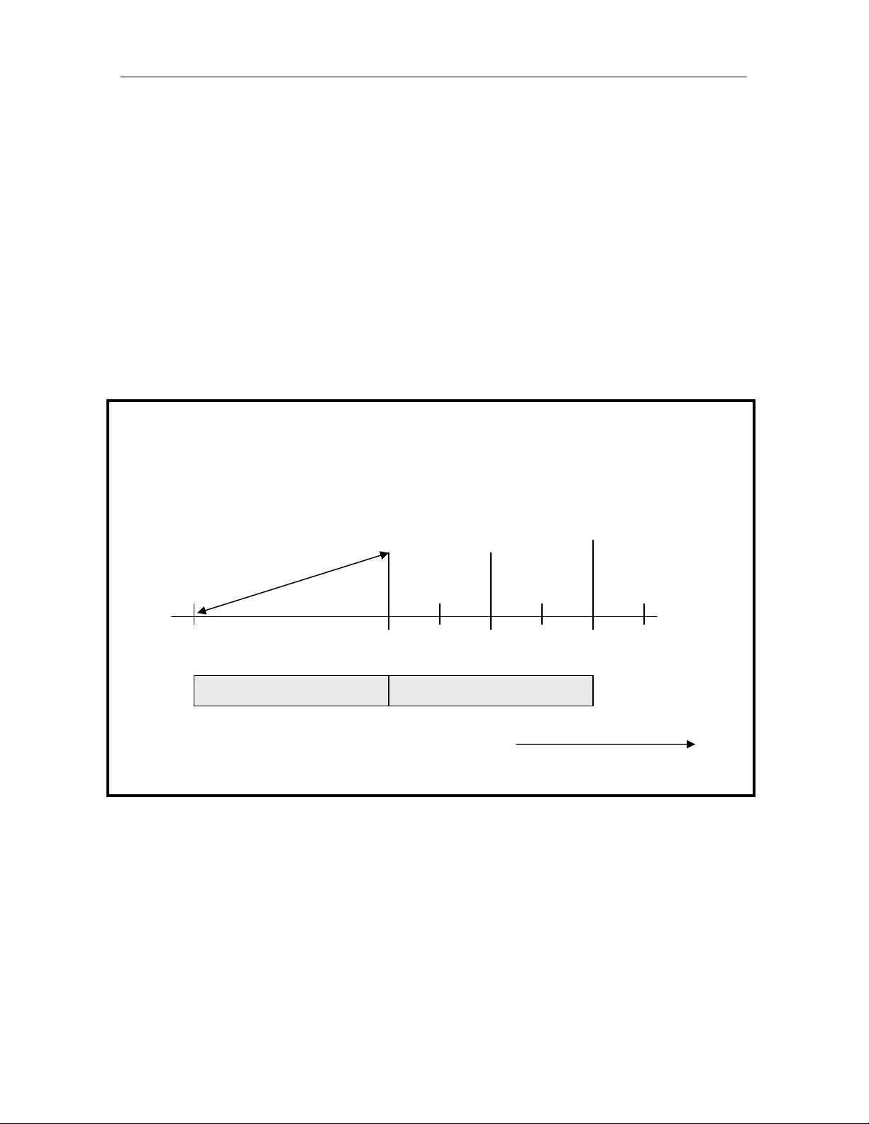
Glycool at 100% Capacity – No Dead Band
Temp Set Point + (1/2 Proportional Band + 1/2 Proportional Band)
Temp Set Point: 70°
Proportional Band: 8°
Valve
Closed
70 71 72 73 74 75 76 77 78 79
Band 1 Glycool Valve Band 2 Compressors
100%
Open
Cool 1 On
Cool 2 On
Increasing Temperature
19
Page 21
iCOM
Controls Training and Service Manual
Glycool at 50% Capacity – No Dead Band
Temp Set Point + (1/2 Proportional Band + 1/2 Proportional Band)
Temp Set Point: 70°
Proportional Band: 8°
Valve
Closed
100%
Open
Cool 1 On
Cool 2 On
70 71 72 73 74 75 76 77 78 79
Band 1
Band 2 Compressors
Glycool
Valve
Increasing Temperature
Dual Source Cooling
When supplied with the Dual Cooling option, the basic unit is supplied with an
additional coil, piping, valve and a Glycol Fluid Sensor (AQ), which is mounted to
the unit supply fluid line and serves as control interface in determining the system
operation. Selection of the chilled water or compressorized operation is controlled
by microprocessor using this aquastat to sense the water temperature.
The Dual Source Cooling program establishes two distinct control bands for
cooling control operation in the same method as Glycool. The first band controls
the operation of the chilled water valve and the second controls the operation of
the compressors, either 2-stage or 4-stage.
The microprocessor checks the return air temperature and the entering chilled
water fluid temperature to determine a cooling capacity. The chilled water cooling
capacity is considered to be 100% if the entering Chilled Water fluid temperature is
8°F lower than the return air temperature.
When the microprocessor decides that the return chilled water temperature is cold
enough the first cooling band is the modulating valve control method, and the
second band, added to the first band, is for the compressors as in the normal
20
Page 22
iCOM
Control Training and Service Manual
2-Stage or 4-Stage control method. If the chilled water temperature is not cold
enough the valve control band is replaced by the compressor band.
Dual Cooling at 100% Capacity – No Dead Band
Temp Set Point + (1/2 Proportional Band + 1/2 Proportional Band)
Temp Set Point: 70°
Proportional Band: 8°
Valve
Closed
100%
Open
Cool 1 On
Cool 2 On
70 71 72 73 74 75 76 77 78 79
Band 1 Chilled Water
Valvel
Band 2 Compressors
Increasing Temperature
An addition program available with the Dual Cooling option is called Minimum
Chilled Water Temperature. This program allows the end user to select the
minimum chilled water temperature that permits simultaneous operation of the
chilled water control and compressor control. When the supply chilled water
temperature decreases to this programmed value ONLY the chilled water valve
control is operational, the compressors are locked out.
Staged Electric Reheat
The basic temperature heating control band is established at the temperature set
point with the length equal to ½ of the programmed temperature proportional band
divided by the number of reheat stages.
The Liebert DS units are supplied with three (3) reheat stages (elements), each
stage is rated at 1/3 of the unit capacity. The three (3) stages will operate in an
on/ off configuration to reheat the unit discharge air as it enters the space.
The temperature controller activates the first electric heating stage when the return
air temperature decreases to 33% of the heating proportional band. The second
electric heating stage activates when the return air temperature decreases to 66%
21
Page 23
iCOM
of the heating proportional band. The third electric heating stage activates when
the return air temperature decreases to 100% of the heating proportional band.
The temperature controller deactivates the third heating stage when the return air
temperature increases to 66% of the heating proportional control band value. The
second heating is deactivated when the return air temperature increases to 33% of
the heating proportional control band value. The first heating stage is deactivated
when the return air temperature increases to the temperature set point value or
0% of the heating proportional control band value.
Controls Training and Service Manual
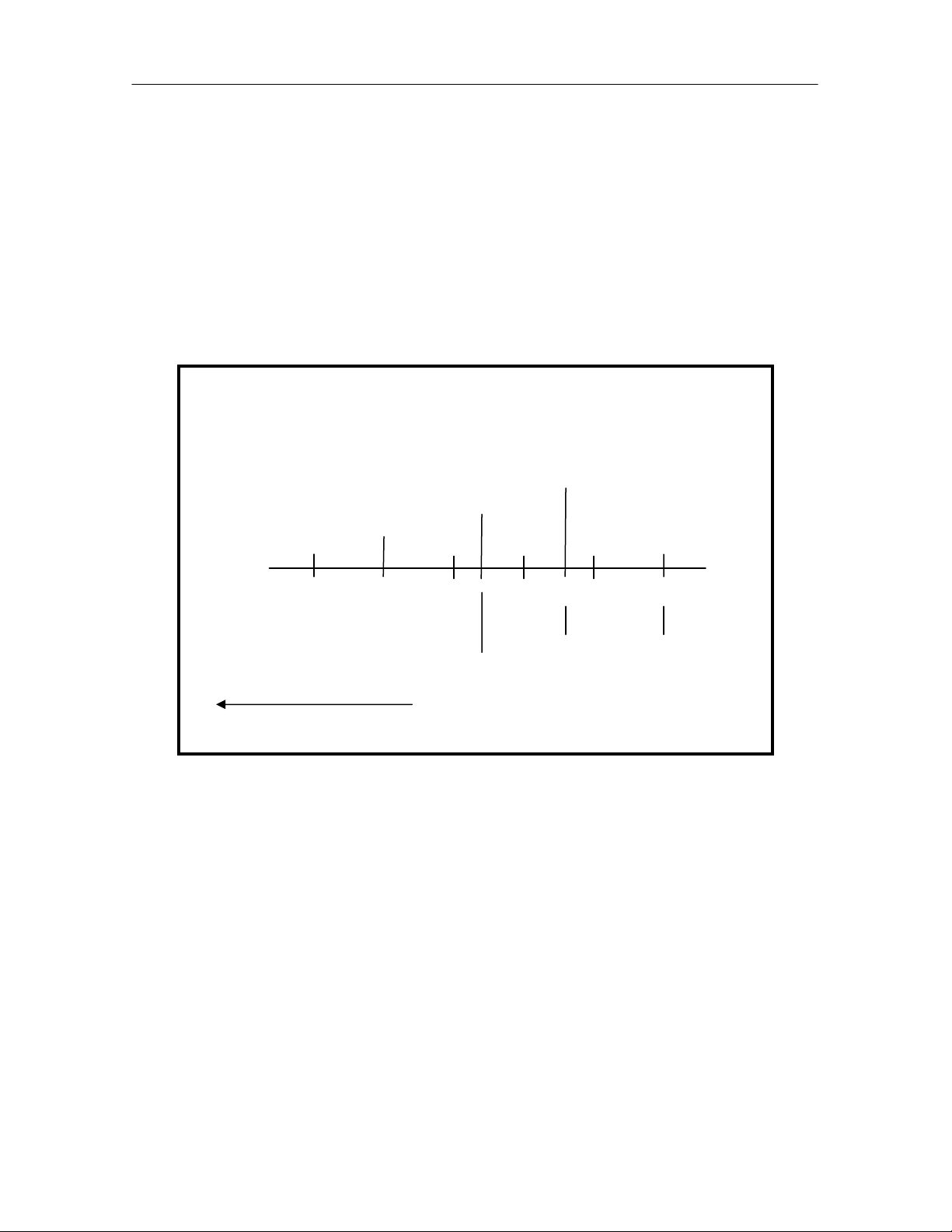
3 Stage Electric Reheat – No Dead Band
Note: in the above example that the control band begins at the 70°F temperature
set point and has a length of 4°F, which is ½ of the programmed temperature
proportional band value.
As the return air temperature decreases Reheat 1 is activated at 68.7°F or 33% of
the heating control band. If the return air temperature continues to decrease
Reheat 2 will activate at 67.4°F or 66% of the heating control band. If the return
air temperature continues to decrease Reheat 3 will activate at 66°F or 100% of
the heating control band.
When the return air temperature starts to increase, Reheat 3 is deactivated at
67.4°F or 66% of the heating control band, Reheat 2 is deactivated at 68.7°F or
33% of the heating control band and Reheat 1 is deactivated at the temperature
set point of 70°F or 0% of the heating control band.
Temp Set Point: 70°F
Proportional Band: 8°F
Decreasing Temperature
Temp Set Point - (1/2 Proportional Band)
Reheat 1 On
Reheat 2 On
Reheat 3 On
65 66 67 68 69 70
Reheat
3 Off
Reheat
2 Off
Reheat
1 Off
22
Page 24
iCOM
Control Training and Service Manual
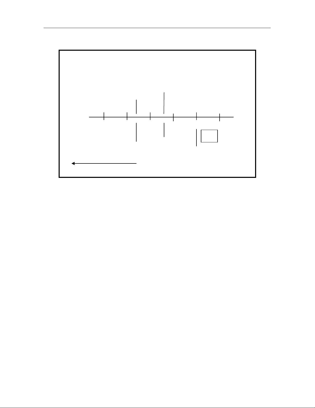
3 Stage Electric Reheat – With Dead Band
Note: in the above example that the control band begins at the 70°F temperature
set point and has a length of 5°F, which is ½ of the programmed temperature dead
band value plus ½ of the programmed temperature proportional band value.
As the return air temperature decreases Reheat 1 is activated at 67.7°F or ½ of
the dead band value plus 33% of the heating control band. If the return air
temperature continues to decrease Reheat 2 will activate at 66.4°F or ½ of the
dead band value plus 66% of the heating control band. If the return air
temperature continues to decrease Reheat 3 will activate at 65°F or ½ of the dead
band value plus 100% of the heating control band.
When the return air temperature starts to increase, Reheat 3 is deactivated at
66.4°F or ½ of the dead band value plus 66% of the heating control band. Reheat
2 is deactivated at 67.7°F or ½ of the dead band value plus 33% of the heating
control band. Reheat 1 is deactivated at 69°F or ½ of the dead band value plus
0% of the heating control band.
Remember the temperature dead band value is used by the control to shift the
cooling on/ off operations away from the temperature set point.
Temp Set Point - (1/2 Dead Band + 1/2 Proportional Band)
Temp Set Point: 70°F
Proportional Band: 8°F
Dead Band: 2°F
Reheat 2 On
Reheat 3 On
65 66 67 68 69 70
Reheat
3 Off
Decreasing Temperature
Reheat 1 On
Reheat
2 Off
DB
Reheat
1 Off
23
Page 25

iCOM
Controls Training and Service Manual
Humidity Control
Humidification and/ or Dehumidification Required, in
Percent (%)
The humidity control programs for the iCOM microprocessor is based on a
calculated percent (%RH) requirement for humidification and/ or dehumidification.
This percent (%RH) requirement is determined by the control type (algorithm)
selected by the user.
The two (2) user selectable humidity control programs are:
• Absolute Humidity, grains of moisture in the air
• Relative Humidity (%RH)
Humidity Control Program Types
Absolute (predictive) Humidity Control – Factory Default Setting
Absolute (predictive) humidity control is based on the moisture content in the
return air. The iCOM microprocessor control automatically adjusts the humidity
control as the return air temperature deviates from the programmed temperature
set point. This calculation converts the return temperature and humidity values to
a moisture content value defined as either grains per cubic foot or grains per
pound. This recalculated content value is compared to the content control band
that is determined by the:
• Programmed temperature set point
• Programmed humidity set point in %RH
• Programmed humidity proportional band in %RH
This automatic adjustment results in a predictive humidity control response. With
absolute humidity control, the humidity control program is automatically adjusted
approximately 2% RH for each degree difference between the return air
temperature and the temperature set point. Note the following example:
24
Page 26
y
y
y
Temperature
Set Point
Humidity
Set Point
iCOM
Proportional
Control Training and Service Manual
Humidity
Band = 6%
Content Level
Grains per LB.
75°F
75°F
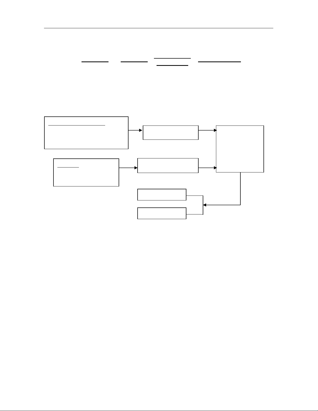
The Absolute (Predictive) Humidity Control Flowchart shows what the program is
doing and why.
Programmed Values
Temp Set Point
Humidity Set Point
Humidit
The program can be analyzed using the Moisture Content Charts supplied in a
later chapter of this manual. It is important to remember that the display provides
the humidity value in %RH, not moisture content. The moisture content (grains)
values are used only in the internal control program calculation. The LCD display
will indicate relative humidity percentage for both methods of control. If the
absolute method of control is selected, the adjusted humidity reading will be
shown.
When utilizing the absolute (predictive) humidity control program feature,
the humidity level is automatically adjusted ~ 2% RH for each degree
difference between the return air temperature and the temperature set point.
When absolute humidity control is used, over dehumidification is avoided in the
space. When overcooling occurs, causing an increase in the relative humidity
reading, the humidity control program “predicts” what the RH will be when the
dehumidification cycle ends and the temperature returns to the programmed set
point. This allows the dehumidification cycle to end at the proper time.
Proportional Band
Present
Room Temperature
Room Humidity
50% +3% 59.2
50% -3% 52.5
Calculates Band
Calculates Content
Humidif
Dehumidif
Compares
Moisture
Content to
Band and
Makes
Decision
25
Page 27

iCOM
Controls Training and Service Manual
Relative Humidity Control
Relative humidity control is based on the humidity content in the return air. The
iCOM microprocessor control determines the unit humidification/ dehumidification
operation by comparing the return air humidity value to the control band that is
determined by the:
• Programmed humidity set point in %RH
• Programmed humidity proportional band in %RH
Operations and Charts
The humidity proportional control band value is divided into two parts: the humidity
set point plus ½ of the programmed humidity proportional band for
dehumidification operation and the humidity set point minus ½ of the programmed
humidity proportional band for humidification operation.
A humidity dead band can also be programmed into the control to shift the
humidification and/ or dehumidification on/ off operations away from the humidity
set point.
This programmed humidity dead band value is divided into two parts: the humidity
set point plus ½ of the dead band – no dehumidification operation and the humidity
set point minus ½ of the band – no humidification operation.
The humidity set point range is adjustable from 1 – 80% RH in increments of 1%
RH. The humidity proportional band range is adjustable from 1 – 20% RH in
increments of 1% RH. The humidity dead band range is adjustable from
0 – 50% RH in increments of 1% RH.
Humidifier Operation
The Relative Humidity control program is used to illustrate the humidification
operation in the following examples. The basic humidification control band is
established at the humidity set point with the length equal to ½ of the programmed
humidity proportional band value. The Liebert DS units are supplied with an
infrared humidifier rated at the unit capacity.
The humidity controller activates the infrared humidifier when the return air
humidity level decreases to 100% of the humidity proportional band. The
humidifier makeup water solenoid valve also operates during humidification
operation based on a timing sequence.
The humidity controller deactivates the infrared humidifier and makeup water
solenoid valve when the return air humidity level increases to 50% of the humidity
proportional control band value.
26
Page 28
iCOM
Control Training and Service Manual
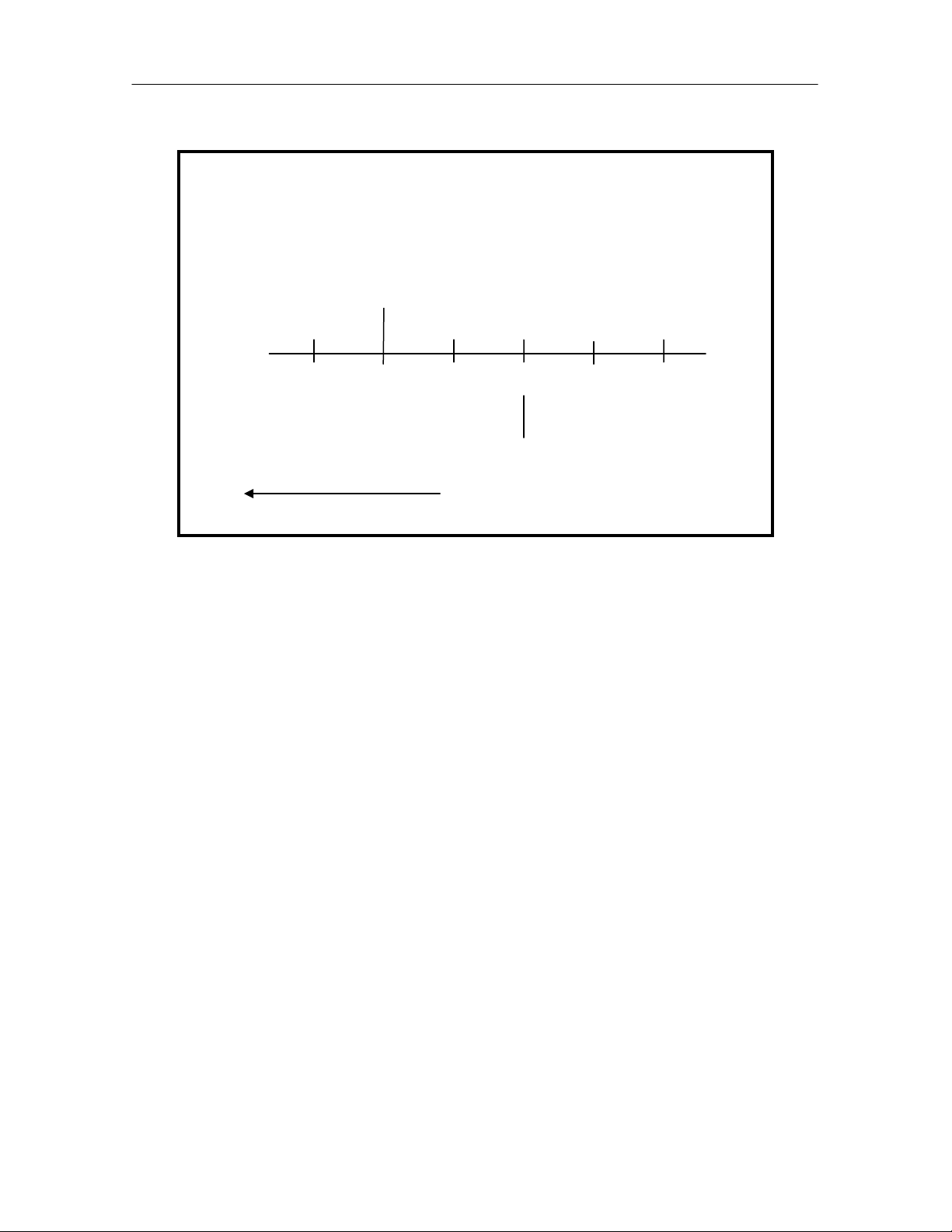
Infrared Humidification – No Dead Band
Note: in the above example that the control band begins at the 50% humidity set
point and has a length of 4%, which is ½ of the programmed humidity proportional
band value.
As the return air humidity decreases the infrared humidifier is activated at 46%RH
or 100% of the humidification control band. When the return air humidity starts to
increase, the infrared humidifier is deactivated at 48%RH or 50% of the
humidification control band.
Humid Set Point: 50%
Proportional Band: 8%
Humidity Set Point - (1/2 Proportional Band)
Humidification On
45 46 47 48 49 50
Humidification Off
Decreasing Humidity
27
Page 29
iCOM
Controls Training and Service Manual
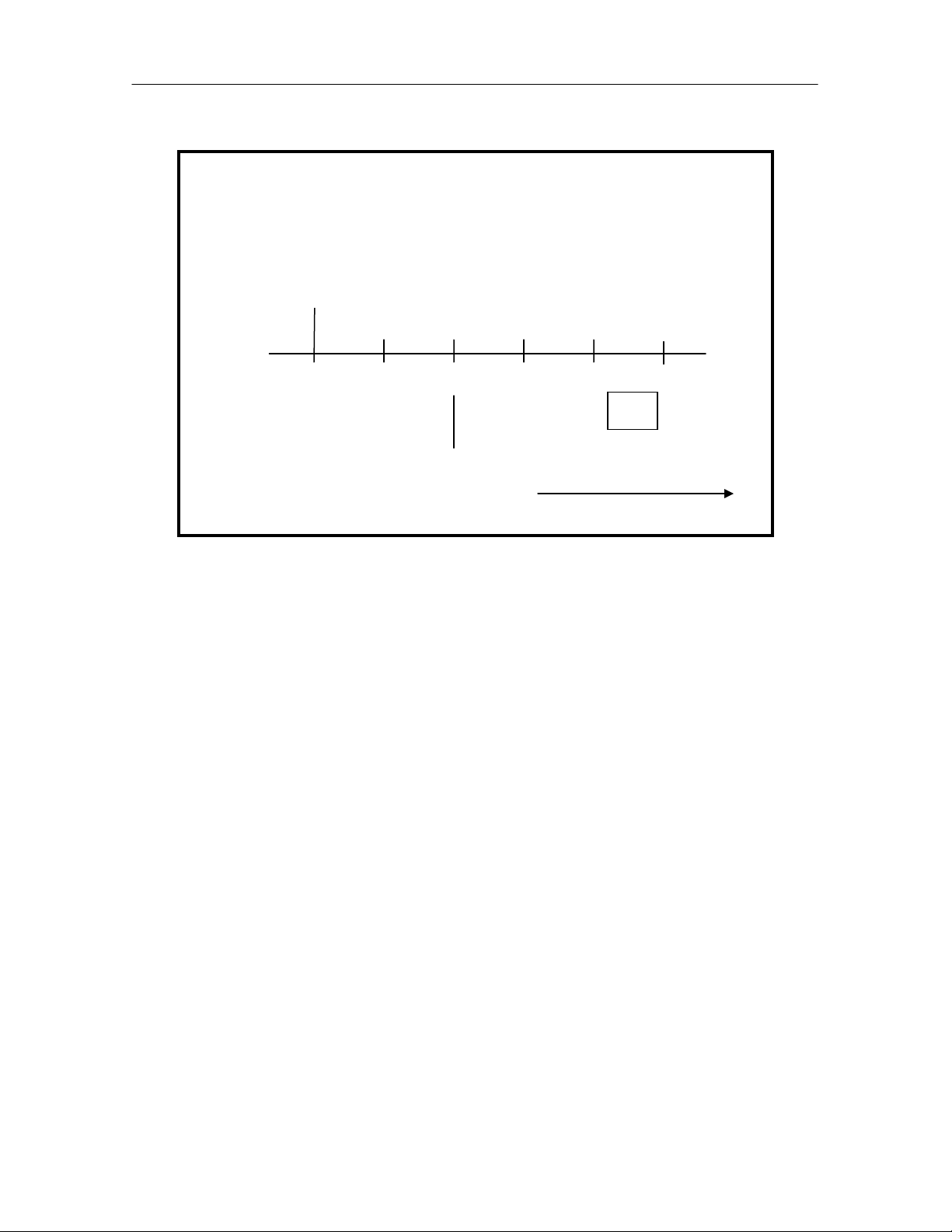
Infrared Humidification – With Dead Band
Note: in the above example that the control band begins at the 50% humidity set
point and has a length of 5%, which is ½ of the programmed dead band value plus
½ of the programmed humidity proportional band value.
As the return air humidity decreases the infrared humidifier is activated at 45%RH
or ½ of the dead band value plus 100% of the humidification control band. When
the return air humidity starts to increase, the infrared humidifier is deactivated at
47%RH or ½ of the dead band value plus 50% of the humidification control band.
Humidity Set Point - (1/2 Dead Band + 1/2 Proportional Band)
Humid Set Point: 50%
Proportional Band: 8%
Dead Band: 2%
Humidification On
45 46 47 48 49 50
DB
Humidification Off
Increasing Temperature
Autoflush Control for Infrared Large (IFL) or Small (IFS)
Pans
The Autoflush Water-Level Control software program is an integral part of the
infrared humidifier system. The program automatically controls a water makeup
valve to maintain the proper water level in the humidifier pan during operation.
When a call for humidification exists, the program performs a series of checks.
The first check to see how long the infrared humidifier has been off. If the off time
is equal to or greater than the programmed value (factory default is 15 hours), it is
assumed that the pan is dry and a program called pre-fill is initiated to add water to
the pan. During the pre-fill operation the infrared lamps are inactive. The pre-fill
time is programmable with an adjustable range of 1 to 120 seconds for either pan
size. The factory default for a large (IFL) pan is 60 seconds and for a small (IFS)
pan is 30 seconds.
28
Page 30
iCOM
–
If the off time is less than 15 hours (or user programmed value) the pre-fill program
is bypassed and the infrared lamps and water valve are activated at the same time
to fill the pan to the proper water level and initiate humidification.
During normal infrared humidification operation the water makeup valve is
periodically closed (no pan fill) and opened (pan fill) based on a timing sequence
to allow for the evaporation of water from the pan (see flow chart below).
With the humidifier water flush rate set at the factory default value of 150% the
water makeup valve will open for 7 minutes of fill time with an off time of 45
seconds between fill cycles for a small pan. For a large pan water makeup valve
will open for 10 minutes of fill time with an off time of 80 seconds between fill
cycles. The user can modify the percentage from 110% to a maximum of 500% in
1% increments.
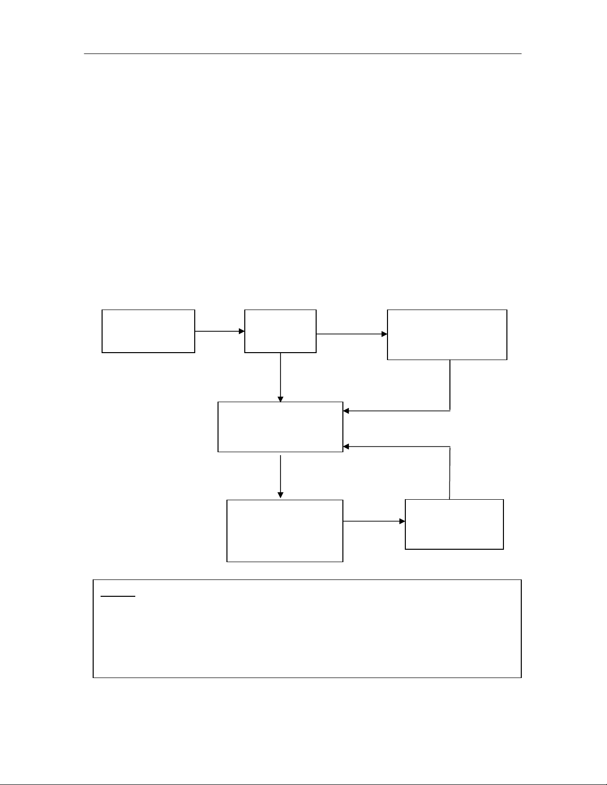
Autoflush Control Flow Chart
Control Training and Service Manual
Call for
Humidification
On in last
15 Hours?
YES
NO
HMV Pre-fill
30 sec – small pan
60 sec – large pan
HMV and Lamps on
4 min – small pan
7 min – large pan
Humidification
Lamps only
8 min – small pan
10 min
large pan
Refill
110% to 500%
Notes:
1. IFL: Infra-red Large and IFS: Infra-red Small
2. Last 15 Hours is programmable from 1-120hours.
3. Pre-fill time is programmable from 1-120 seconds on Large or Small pans
4. Normal Fill is programmable from 1-120 seconds
5. Refill is programmable in 1% increments
29
Page 31

iCOM
Controls Training and Service Manual
Dehumidification Operation
The Relative Humidity control program is used to illustrate the dehumidification
operation in the following examples. The basic dehumidification control band is
established at the humidity set point with the length equal to ½ of the programmed
humidity proportional band value.
The humidity controller activates dehumidification operation when the return air
humidity level increases to 100% of the humidity proportional band. The humidity
controller deactivates dehumidification operation when the return air humidity level
decreases to 0% of the humidity proportional control band value.
1-Stage Dehumidification, Compressorized Direct Expansion (DX)
Systems
The Liebert DS unit is supplied with two (2) compressors. Under normal
operation, the lead compressor is used for sensible cooling and the lag
compressor is used for either additional cooling or for dehumidification control.
The optional hot gas bypass solenoid valve is de-energized during
dehumidification.
If single compressor dehumidification is selected, the lag compressor is activated
by the humidity controller when the return air humidity level increases to 100% of
the humidity proportional band.
The humidity controller deactivates the lag compressor when the return air
humidity level decreases to 50% of the humidity proportional control band value.
1 Stage Compressorized Dehumidification – No Dead Band
Humid Set Point: 50%
Proportional Band: 8%
Humidity Set Point - (1/2 Proportional Band)
Dehumidification On
50 51 52 53 54 55
Dehumidification Off
Increasing Humidity
30
Page 32

iCOM
Note: in the above example that the control band begins at the 50% humidity set
point and has a length of 4%, which is ½ of the programmed humidity proportional
band value.
As the return air humidity increases, dehumidification operation is activated at
54%RH or 100% of the dehumidification control band. When the return air
humidity starts to decrease, dehumidification operation is deactivated at 52%RH or
50% of the humidity proportional control band.
Control Training and Service Manual
1 Stage Compressorized Dehumidification – With Dead Band
Note: in the above example that the control band begins at the 50% humidity set
point and has a length of 5%, which is ½ of the programmed dead band value plus
½ of the programmed proportional band value.
As the return air humidity increases, dehumidification operation is activated at 55%
RH or ½ of the dead band value plus 100% of the dehumidification control band.
When the return air humidity starts to decrease, dehumidification operation is
deactivated at 53%RH or ½ of the dead band value plus 50% of the humidity
proportional control band.
Humidity Set Point - (1/2 Dead Band +1/2 Proportional Band)
Humid Set Point: 50%
Proportional Band: 8%
Dead Band: 2%
Dehumidification On
50 51 52 53 54 55
DB
Dehumidification Off
Increasing Humidity
2-Stage Dehumidification, Compressorized Direct Expansion (DX)
Systems
The basic dehumidification control band is established at the humidity set point
with the length equal to ½ of the programmed humidity proportional band value.
When 2 stage dehumidification is selected, the controller works as follows.
31
Page 33
iCOM
The humidity controller activates the first stage of dehumidification operation when
the return air humidity level increases to 50% of the humidity proportional band.
The second stage of dehumidification is activated when the return air humidity
level increases to 100% of the humidity proportional band.
The humidity controller deactivates the second stage of dehumidification operation
when the return air humidity level decreases to 50% of the humidity proportional
control band value. The first stage of dehumidification is deactivated when the
return air humidity level decreases to the humidity set point of 50% or 0% of the
humidity proportional band.
If the compressors have unloading capability (4-stage cooling), then the
compressors are activated in the fully loaded condition for each stage of
dehumidification.
Controls Training and Service Manual
2 Stage Compressorized Dehumidification – No Dead Band
Note: in the above example that the control band begins at the 50% humidity set
point and has a length of 4%, which is ½ of the programmed humidity proportional
band value.
As the return air humidity level increases, first stage dehumidification operation is
activated at 52%RH or 50% of the dehumidification control band. If the return air
humidity level continues to increase the second dehumidification stage actives at
54%RH, which 100% of the dehumidification control band.
Humid Set Point: 50%
Proportional Band: 8%
Humidity Set Point + (1/2 Proportional Band)
Dehumid
Stage 1 On
50 51 52 53 54 55
Dehumid
Stage 1 Off
Dehumid
Stage 2 Off
Dehumid
Stage 2 On
Increasing Humidity
32
Page 34
iCOM
When the return air humidity level decreases to 52%RH or 50% of the
dehumidification control band the second dehumidification stage is deactivated.
When the return air humidity level decreases to the humidity set point of 50% or
0% of the humidity proportional band the first dehumidification stage is
deactivated.
Control Training and Service Manual
2 Stage Compressorized Dehumidification – With Dead Band
Note: in the above example that the control band begins at the 50% humidity set
point and has a length of 5%, which is ½ of the programmed dead band value plus
½ of the programmed humidity proportional band value.
As the return air humidity level increases, first stage dehumidification operation is
activated at 53%RH or ½ of the programmed dead band value plus 50% of the
dehumidification control band. If the return air humidity level continues to increase
the second dehumidification stage actives at 54%RH or ½ of the programmed
dead value plus 100% of the programmed humidity proportional control band.
When the return air humidity level decreases to 53%RH or ½ of the programmed
dead band value plus 50% of the programmed proportional control band the
second dehumidification stage is deactivated. When the return humidity level
decreases to 51%RH or ½ of the dead band value plus 0% of the programmed
proportional control band the first stage dehumidification deactivated.
Humidity Set Point + (1/2 Dead Band +1/2 Proportional Band)
Humid Set Point: 50%
Proportional Band: 8%
Dehumid
Stage 1 On
50 51 52 53 54 55
DB
Dehumid
Dehumid
Stage 1 Off
Stage 2 Off
Increasing Humidity
Dehumid
Stage 2 On
Reheating during Dehumidification
The Parameter Electric Reheat Enabled defines how the reheats react when the
return air temperature decreases below the temperature set point during the
33
Page 35

iCOM
dehumidification process. The end user can choose to select from the following
selections:
Controls Training and Service Manual
Parameter Operation
No
Normal
Delayed
No electric reheat allowed during compressorized
dehumidification operation.
Electric reheat operates as normal. A decrease in
return air temperature below set point will start
reheats as described previously in his chapter.
No low limit reached / low limit reset: heaters
disabled. Only one of two compressors operating in
dehum or low limit 1 reached: heaters enabled
Normal or Delayed Reheat (2-Stage Dehumidification Only)
When normal reheat (factory default) control is selected, the unit reheats are not
disabled during dehumidification, even if both compressors are operating. As the
return air temperature decreases below the temperature set point the reheats will
stage on and off as described earlier in this chapter.
If delayed reheat is selected and both compressors are operating for
dehumidification control, the reheats are disabled until only one compressor is
required. If, during reheat disable, the return air temperature decreases far
enough below the temperature set point to require 150% total available reheat
capacity, then dehumidification is disabled and reheats are activated.
When the return temperature raises to the point where reheat is no longer
required, then dehumidification operation is re-enabled. However, if the amount of
time that both compressors were operating prior to being disabled by the low
temperature condition was less than 10 minutes, then only one compressor is
allowed to operate for subsequent dehumidification requirements. This prevents
excessive system cycling, which can occur if the room heat load is small. Once
the requirement for dehumidification is no longer present, then both compressors
are enabled.
Caution:
Dehumidification with normal reheat allows for operating both compressors and
reheats simultaneously. It is very important that the electrical service to the unit be
sized and wired for this option if selected. If not sized properly the electrical
service could experience nuisance trips and or possible damage to building circuit
breakers (or Fuses) and wiring.
34
Page 36

iCOM
Control Training and Service Manual
Additional Programs
Start
The unit fan is activated. The unit can be switched on/ off from 2 inputs:
1. Remote on/ off input (RSD – Remote Shutdown Device)
2. Display button
Note: Switches 1 and 2 are in series; the unit will start only if both switches are in
the on position. If either switch is in the off position the unit will stop
Remon/off
Display button(s)
Auto restart
When there is a power outage the unit will provide an automatic restart on power
restoration when programmed. The unit will start and the loads will sequence on
with the Fan first, the first Cooling need and so forth until all loads are on as the
room requirement demands.
The Unit Auto Restart Sequence (customer programmable) takes place. Each
unit will restart by this program, however, with a network of units, the start loop will
start the next unit at each individual time when elapsed beginning with unit num
ber
ID #1. The unit control start sequence will start at this point as well.
Power on
Unit 1
on
Unit 2
on
Unit 3
on
Unit 4
on
Autorestart
Boot seque nce
Autorestart
Control 1
on
Autorestart
Control 2
on
35
Autorestart
Control 3
on
Control 4
on
Page 37

iCOM
Controls Training and Service Manual
Fan Alarm / Fan settings
The fan operation is controlled by two (2) digital devices: the Loss of Airflow
differential pressure switch and the Main fan Overload motor protection. The
time delay at the unit start is always 5 seconds shorter than the control delay.
High Pressure Cutout
The control uses high head lockout functionality. If one compressor trips or is
locked out on high head, the other compressor turns on when the space
temperature increases 1°F. Pressing the alarm button on the display twice can
reset high head Alarm. A lockout condition occurs on the third trip and must be
reset by turning the main power switch to off then back on
.
Suction Pressure Transducer
The suction pressure transducer operation is only on air conditioning products (not
chiller applications). Transducer measurements are made at least once every 1
second. With all other operating times for all compressors, additional
measurements, shall be taken based on operation “at limit conditions” for 5
seconds and shall not include readings taken during Pumpdown or Winter Start
Kit (WSK) timeout
.
Call for Cooling
The following applies for both R22 and R407C systems and applies to all
compressor types. The call for cooling opens the Liquid Line Solenoid Valve
(LLSV). Note: on units with Digital Scroll Compressors the unloader is energized
0.1 second before the compressor contactor is energized. On air-cooled units with
fan speed type condenser (FSC) the low pressure start threshold is 35psiG
(50psiA). On air-cooled units with lee-temp control (LT) and all fluid cooled
units the low-pressure start threshold is 60psiG (75psiA).
All compressorized units use the following start
sequence:
Open LLSV, if WSK is set to 0, wait for suction pressure to reach setting, then start
compressor and freeze protection timer.
If WSK is set greater than 0, operate the compressor for the WSK override time
and monitor suction transducer value.
If pressure is achieved the compressor is allowed to operate, and the freeze
protection timer is started.
If pressure is not achieved, turn compressor off and leave LLSV open.
If pressure is achieved within next 30 seconds the compressor is allowed to
operate, and the freeze protection timer is started.
36
Page 38
iCOM
Control Training and Service Manual
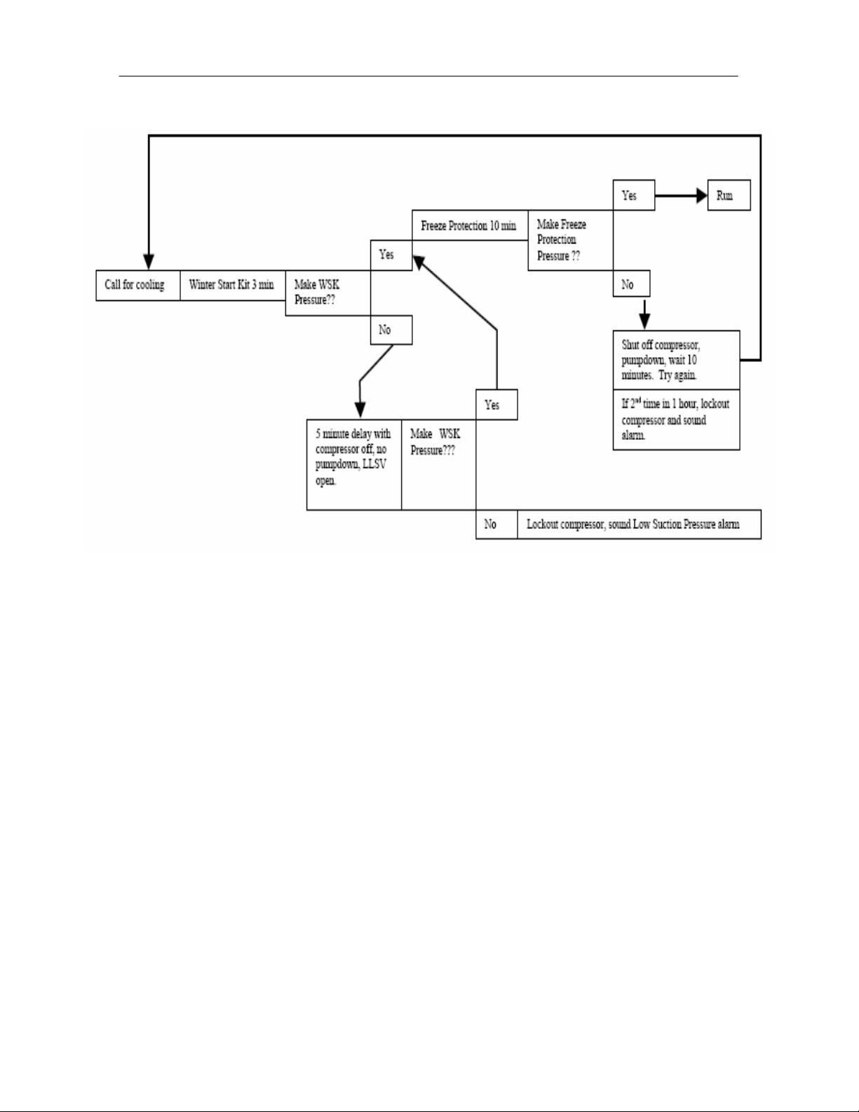
The Startup and Freeze Protection Program
The sequence for the call for cooling with the program features is as follows:
The need for cooling is defined by the control setting for the temperature setpoint,
proportional band, and deadband (if used). At this point the Winter Start Kit (WSK)
time delay is the wait period for the compressor to run without the indication of the
low-pressure condition (also known as LP bypass). The WSK time delay is
programmable with a range of 0 - 5 minutes. If the LP switch setting is achieved in
this time then full cooling is in process with the Freeze Protection (FP) now
watching the LP for an additional 10 minutes (fixed). If the LP remains closed the
cooling process continues.
If the WSK is not made in the set time period the cooling process stops and waits
an additional 5 minutes with the compressor off (no pumpdown). The liquid line
solenoid valve will remain open during this time period. If the LP switch is made
the control will now advance and wait for the freeze protection time delay as stated
as above. If the LP switch does not prove in the WSK time delay period plus the 5
minute wait period, the compressor is locked off and the Low Suction Pressure
Alarm will activate. A power off/ on reset is required to reset the cooling function.
If the WSK is made and the control is in the 10 minute Freeze Protection (FP) wait
time period and this function does not prove the LP the control will go into
additional 10 minute wait (fixed), with the compressor off (no pumpdown) and the
liquid line solenoid valve to remain open. If the freeze protection does not make
37
Page 39

iCOM
Controls Training and Service Manual
during the second time frame the cooling process locks off and will require a
power off sequence.
Next Maintenance Calculation
Foreword
The next maintenance calculation will help run the Liebert Environmental unit in an
optimum way, to ensure minimum components stress resulting in increased
reliability.
Calculation of next Maintenance Parameters
The following components are included in the calculation individually:
• Fan(s)
• Compressor 1
• Compressor 2
• Electric Heaters
• Humidifier
For each individual component the next maintenance will be calculated from
following parameters:
1. Standard service interval (1, 2, 4 or 6 times a year, to be programmed).
2. Working hours (counted).
3. Number of starts (counted).
4. Average running time (calculated).
5. Optimum number of starts per hour (to be programmed).
6. Maximum number of starts per hour (to be programmed).
7. Maximum bonus to enlarge time to next maintenance (to be programmed).
8. Maximum penalty to reduce time to next maintenance (to be programmed).
The Maintenance Calculation is done as follows:
Basic: maintenance frequency (1). The control counts the working hours of the
component, as well as the number of starts.
The working hours and the number of starts are compared with the programmed
optimum / maximum starts per hour. This results in “Wellness Factor”.
This factor, in accordance to the service interval, will add a “Bonus” to increase the
time before the next maintenance, or will add a “Penalty” to decrease the time
before the next maintenance. In simple words: If a component starts very often,
the time to next maintenance will be decreased, if it starts rarely, the time to next
maintenance will be increased.
38
Page 40

iCOM
Control Training and Service Manual
The control always takes the component with the most on/ off (cycling) as the
reference component, which asking for the nearest maintenance (example: if the
fan runs continuously, but the compressor switches on/off all the time, the next
maintenance will be calculated from the compressor).
Alarms or warnings (like clogged filter, high or low pressure, fans alarm etc.) will
decrease the time to next maintenance immediately to 0. If the alarm was reset,
the original situation will be displayed again, but the alarm will be counted in the
diagnostics window.
The display’s main window provides information about the next maintenance:
a bar graph (graphical display screen) will fill in, as the next maintenance gets
closer (the width of the graph equals to the standard maintenance Interval (1, 2, 4
or 6 times a year). The date of the next maintenance is also displayed.
Parameters for next Maintenance Calculation:
General Maintenance Settings:
Maintenance Frequency: can be set at 1, 2, 4 or 6 times a year. “NO” means
the maintenance calculation program is disabled.
Maximum Bonus: this value increases the time to next maintenance with the set
value, if all components run in optimum way (number of starts, average running
time).
Maximum Penalty: this value decreases the time to next maintenance with the
set value, if some components run in non-optimum way (number of starts, average
running time).
Last Maintenance: this date can be will be set by the calculations and the
service-engineer and others to view.
Service-Engineer: name can be added and edited.
Reset: puts all counters of all components (fans, compressors, ect.) to 0, and
starts new maintenance calculation (always reset after maintenance is completed).
Fans / Heaters / Humidifier Settings / Compressor 1 /2 Settings
Number of starts and Working hours: counted from the last maintenance. Total
working hours can be read in the standard working hours window (customer
window).
Average Working Hours: calculated by the number of starts and working hours
of each component.
39
Page 41

iCOM
Starts per Day Optimum: the number of individual component starts that is
considered as good or optimum. To be set by Service Engineer.
Starts per Day Worst: the number of individual component starts that is
considered as “hunting” or worst case. To be set by Service Engineer.
Number of Alarms: counts the number of alarms occurring between service
intervals.
Actual Bonus: calculated from “number of starts” and “average working time”
values. The result can be positive (for a bonus) or negative (for a penalty). This
value influences the time remaining to the next maintenance.
Controls Training and Service Manual
Shared Parameters an understanding
If we have multiple units in the same room (zone) they will need to communicate
with each other to avoid opposite operational functions. This will prevent the
cooling and heating functions from operating at the same time on different units.
This condition called “fighting “ often exists in the room due to imbalanced loads
and the crossing of airflow conditions. This is also considered when using the
Lead/ Lag and Cascade functions.
When a system is setup the parameters are shared by all units. The unit selected
as the Lead Unit (#1 unit) is used to program the system, if program parameters
are not set in this unit they will be ignored. This is true for all of the active units in
the system. However, if a unit in the system is not active it will be ignored until it is
active and the parameters will be shared within 2 minutes of activation.
Shared Temperature and Humidity parameters example:
Two units share the master Temperature Control (1/2) Proportional Band Setting
such as 10°F, and then each unit will use the master band divided by 2 (units) or
5°F proportional bands. To avoid the cooling hunting process or compressor
cycling too quickly, the primary temperature proportional band needs to be set
wide enough to compensate for the number of units in the system setup. Note that
shared parameters are not used on single unit applications.
Heating, humidification, and dehumidification will follow the same example with
each function starting in each unit one after the other or in sequence.
In Chilled Water units all valves operate are in parallel but this operation may be
overridden by the setting and use of the Supply Limit sensor. This parameter is
controlled by the individual unit. Here we may see uneven valve positioning
(operation) in some of the units.
40
Page 42

iCOM
Freecooling and Dual cooling will operate in the same manner as chilled water
with the supervision of the Supply Limit, again showing different valve positions on
the units
If in a Freecooling or Dual Cooling unit if the limit of the coil operation is detected
(no free cooling or no CW available) the valve will close off and unit will become
DX operation in the system.
Control Training and Service Manual
Networking and Functions
Unit 2 Unit (U2U) Communications by networking will allow the following
functions to be placed into operation when the requirements exist. The user
must install the correct hardware and properly program the units for the
functionality.
In the iCOM Network the owner may perform the following functions:
The Teamwork Mode functions, which allow multiple stages of Cooling/ Heating
and/ or Humidification/ Dehumidification. The ability to prevent the units fighting is
included in this feature.
The Lead/ Lag function, which allows one or more units to be set as “Running and
Standby” for activation in case of an alarm. This also has the ability to be
programmed in a rotation for assurance of functional standbys.
The Cascade function, which allows additional units to be staged on based on the
temperature or humidity requirement.
Understanding the iCOM Network setup process:
To setup a system network with the iCOM control requires a complete
understanding of the control processes and parameter programming to insure the
proper functional operation without incident. To insure the setup is correct and
that the operation will function as selected you need to map both the room layout
and the unit setup. First, read and record all programmed settings in all of the
single units. Second, document the network parameter settings that are needed
and identify the numerical order of the units to be networked. The order of the
setup process is very important.
41
Page 43

iCOM
Controls Training and Service Manual
The Basics for Cooling Unit Placement:
Installation instructions are found in the product manuals for the Cooling units.
Networking setup should include these additional factors for planning.
• Locations of heat loads in conditioned space.
• Air distribution for cooling.
• Number of operating units versus standby.
The Basics for Hardware:
Multi-unit networking requires the following hardware:
Minimum Network Switch Requirements:
• IEEE 802.3, IEEE 802.3u
• 10/100 Mbps speed
• Multiple RJ-45 ports – one shared RJ45 uplink
CAT 5 patch cables (straight through) in the proper lengths not to exceed
150 ft. maximum length each. One for each board and display added into
the iCOM network. Cable management will apply.
The Basic for Programming:
An IP address number will be used to identify each receiver/ sender of information.
(See Computer and Network Terms in Training and Service Manual)
The iCOM Network is a Class C Private Network and will use the 192.168.254.xxx
series of static IP address. This has nothing to do with the local building or owner
network. The iCOM Network may only be attached to these networks through a
WEB Card or 485 Card using the Liebert Intellislot.
A series of basic rules must be followed to connect and program the units for this
private iCOM Network. See the following rules.
1. Small Displays are CAN connections only, programming of single unit
parameters is required.
2. Small Displays CANNOT look at or program other iCOM Network functions.
3. Small Displays may be networked with a CAT 5 crossover cable (2 units).
4. All Large Displays and Control Boards will use a CAT 5 or greater straight
through (patch) cables to connect to the switch.
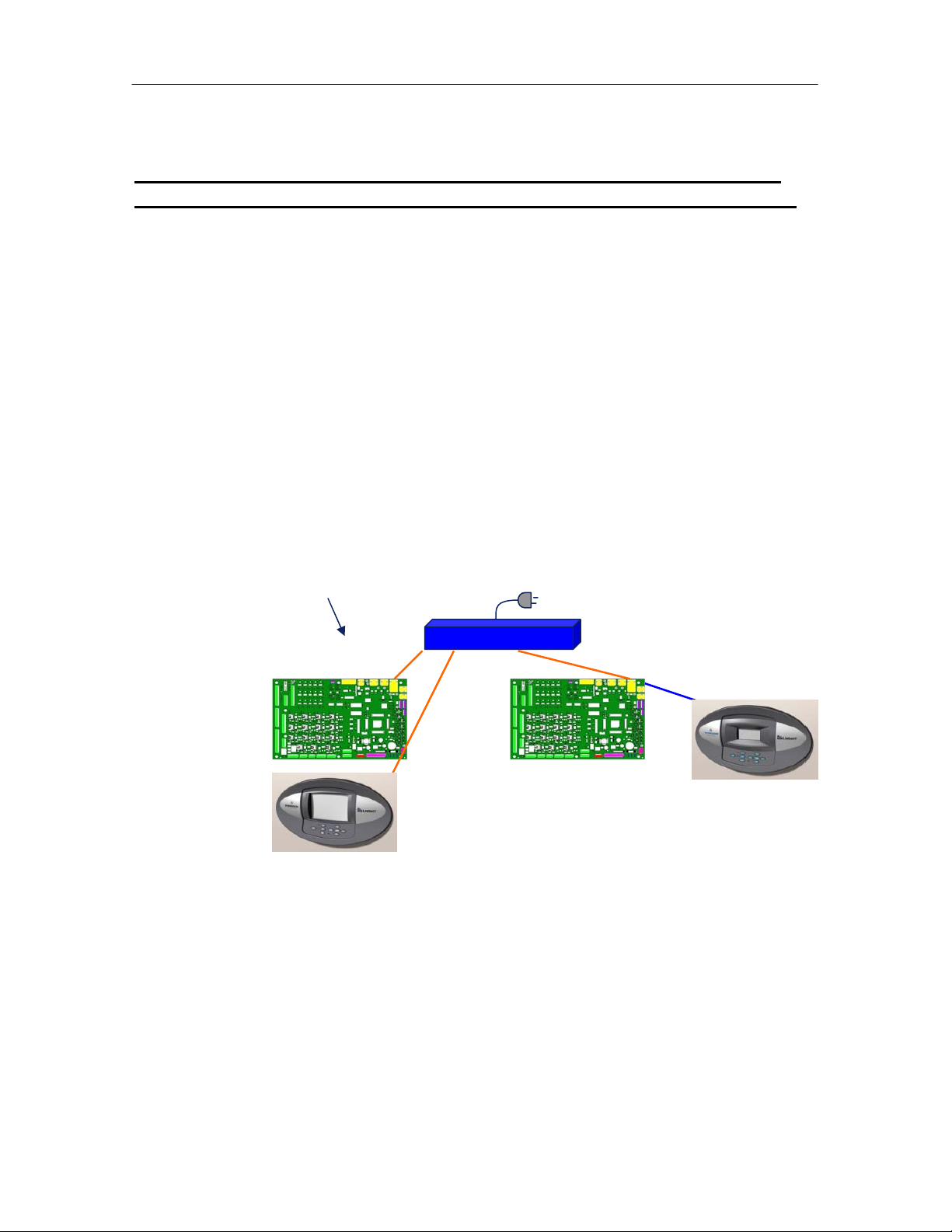
5. One large Display (Wall Mount) with a separate power adapter may be used
with multiple units (Control Boards and Small Displays) through the network
switch.
42
Page 44

iCOM
6. Each set of unit control boards must be set up individually, then connected to
the network switch and checked before the next board can be setup
6a. Large Displays and Control Boards must each be programmed with a
different IP Address.
Example: Display: 192.168.254.001
Example: Control Board: 192.168.254.010
6b. Each Display and Control Board in the iCOM network must have the
same Gateway IP address.
Example: Gateway IP: 192.168.254.75
6c. Each Display and Control Board in the iCOM network must have the
same Netmask IP address.
Example: Netmask IP = 255.255.255.000
6d. The Unit to Unit (U2U) address must be programmed in the necessary
order for setup.
Example: Unit Display: 33 – 64 and Unit Control Board: 1 - 32
Control Training and Service Manual
43
Page 45
iCOM
Controls Training and Service Manual
Setting Parameters
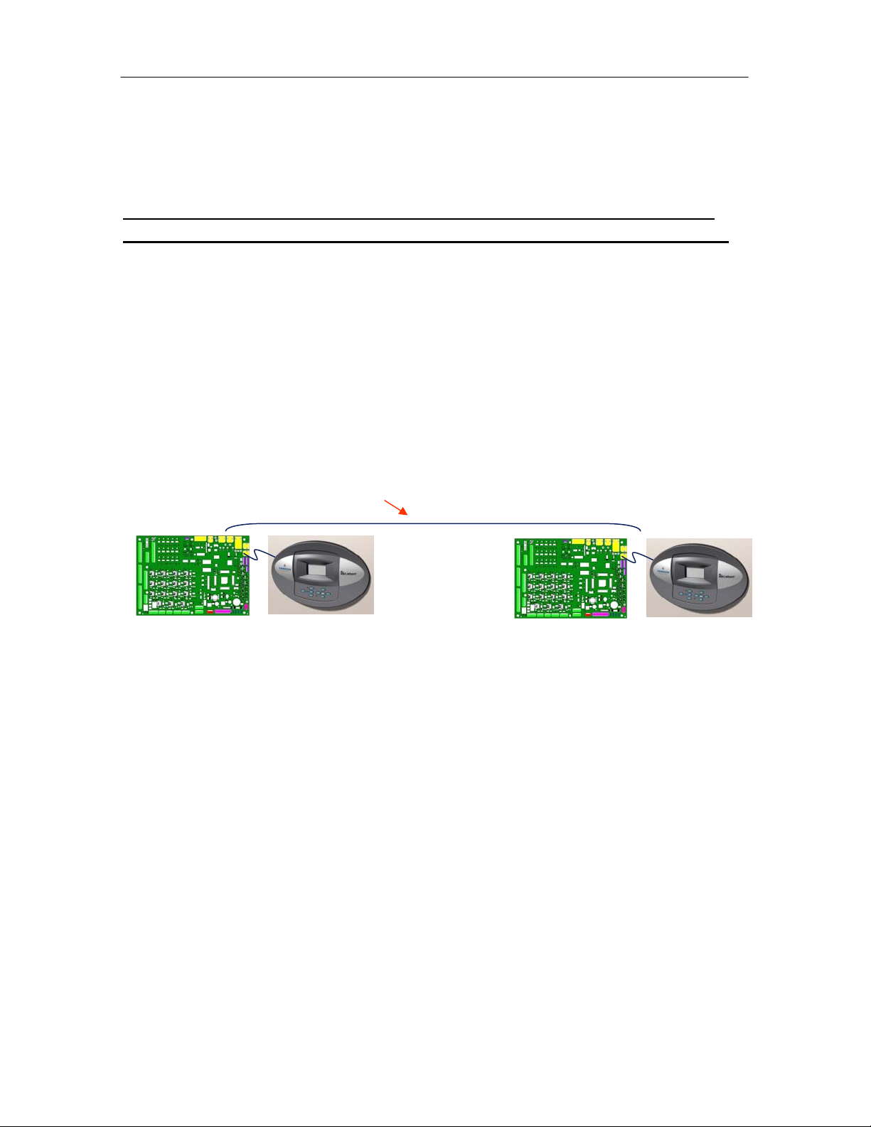
Example: 2 Units with Small Display’s
All Network parameters are viewed and programmed using the
Service Menu function and by selecting the Network Setup Icon
The following example references menu lines on the Network Setup screen:
Line S802: Number units connected: xx (2)
Line S803: Teamwork: xx (No, 1, 2)
Line S804: Control Board IP Address: 192.168.254. xxx (010, 011)
Line S805: Control Board Netmask IP the same for all units
Line S806: Control Board Gateway IP the same for all units
Line S808: U2U address Control Board #: xx (1-2)
Line S810: U2U group #: xx (1)
U2U: CAT5 (Crossover-cable)
Unit No. 1
Unit No. 2
44
Page 46
iCOM
Control Training and Service Manual
Example: 2 Units, One Large Display and One Small Display
All Network parameters are viewed and programmed using the
Service Menu function and by selecting the Network Setup Icon
The following example references menu lines on the Network Setup screen:
Line S802: Number units connected: xx (2)
Line S803: Teamwork: xx (No, 1, 2)
Line S804: Large Display Board IP Address: 192.168.254. xxx (001 - 049)
Line S804: Control Board IP Address: 192.168.254. xxx (050 - 099)
Line S805: Large Display Board Netmask IP: 255.255.255.000
Line S805: Control Board Netmask IP: 255.255.255.000
Line S806: Large Display Board Gateway IP: 192.168.254.255
Line S806: Control Board Gateway IP: 192.168.254.255
Line S808: U2U address Display #: xx (33 - 64)
Line S808: U2U address Control Board #: xx (1 - 32)
Line S810: U2U group #: xx (1 - 99)
CAT5 (Patch-cable) and
(CAN)
Power
45
Page 47
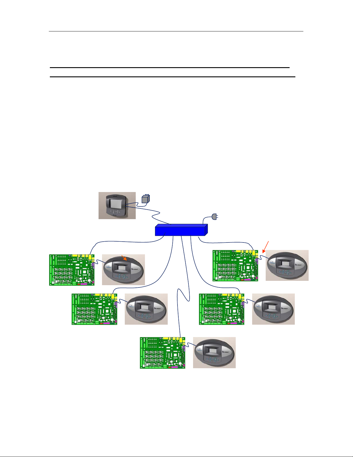
iCOM
Controls Training and Service Manual
Example: Large Wall Display and Five Units with Small Displays
All Network parameters are viewed and programmed using the
Service Menu function and by selecting the Network Setup Icon
The following example references menu lines on the Network Setup screen:
Line S802: Number units connected: xx (01 - 32)
Line S803: Teamwork: xx (No, 1, 2)
Line S804: Large Display Board IP Address: 192.168.254. xxx (001 - 049)
Line S804: Control Board IP Address: 192.168.254. xxx (050 - 099)
Line S804: Wall Mount (LBB) IP Address: 192.168.254. xxx (100 - 149)
Line S806: Large Display Board Gateway IP: 192.168.254.255
Line S806: Control Board Gateway IP: 192.168.254.255
Line S808: U2U address Display #: xx (33 - 64)
Line S808: U2U address Control Board #: xx (01 - 32)
Line S810: U2U group #: xx (01 - 99)
46
Page 48
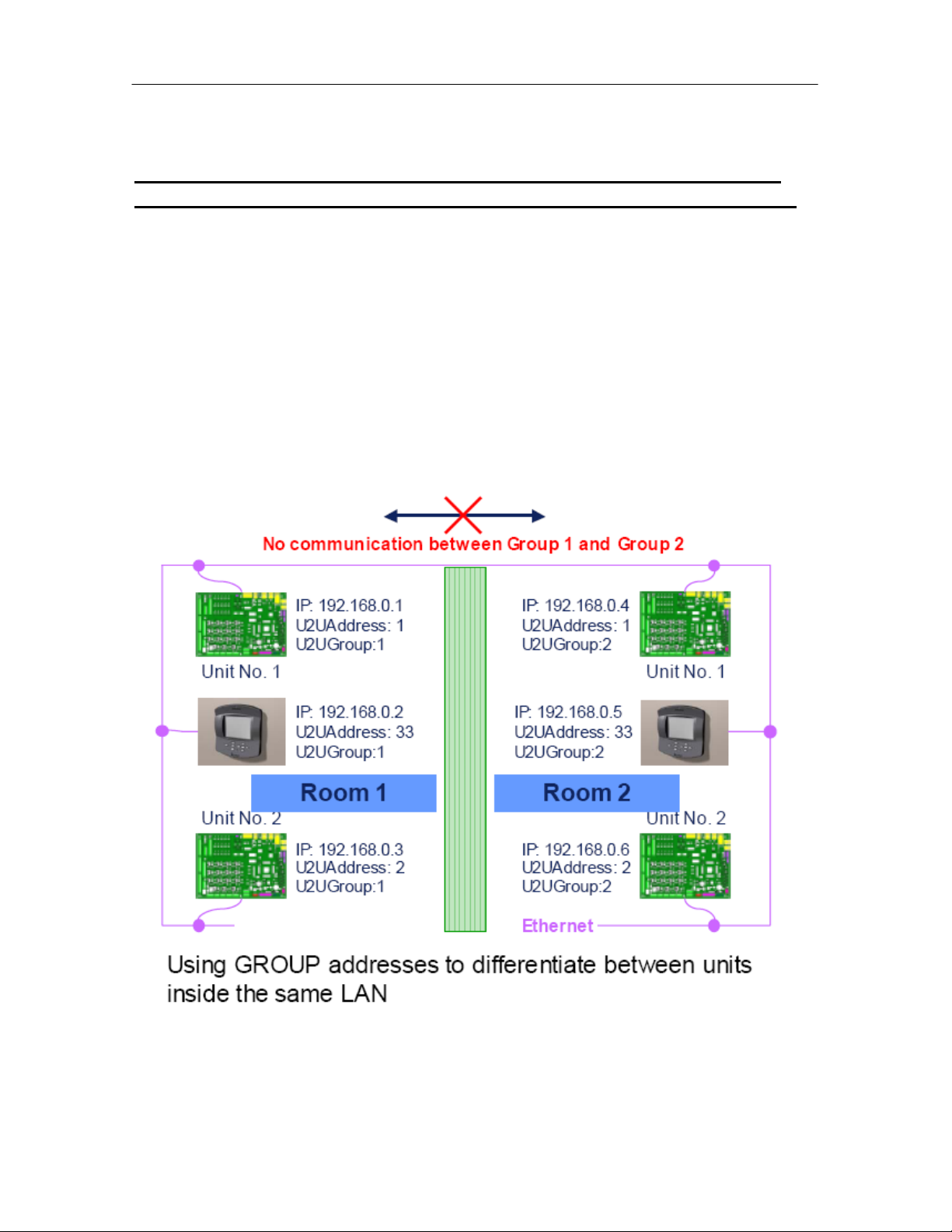
iCOM
Control Training and Service Manual
Example: 4 Units in 2 Groups with 2 Large Displays
All Network parameters are viewed and programmed using the
Service Menu function and by selecting the Network Setup Icon
The following example references menu lines on the Network Setup screen:
Line S802: Number units connected: xx (01 - 32)
Line S803: Teamwork: xx (No, 1, 2)
Line S804: Large Display Board IP Address: 192.168.254. xxx (001 - 008)
Line S804: Control Board IP Address: 192.168.254. xxx (010 - 080)
Line S806: Large Display Board Gateway IP: 192.168.254.xxx (000 – 254)
Line S806: Control Board Gateway IP: 192.168.254.xxx (000 – 254)
Line S808: U2U address Display #: xx (33 - 64)
Line S808: U2U address Control Board #: xx (01 - 32)
Line S810: U2U group #: xx (01 - 99)
47
Page 49

iCOM
Controls Training and Service Manual
Teamwork
Teamwork Modes
Teamwork is the ability to group unit functionality, while connected in a network, to
provide the ability to work together as a team and address control functions in
three different teamwork modes:
“No” Teamwork
In this mode all units are working independently for control and functionality. No
values or sensors are shared. While in this mode units may be setup to provide
the Lead/ Lag function and rotation, however, units may not be setup in the
Cascade functionality.
Teamwork Mode 1
In this mode unit parameters (system settings) are shared if the system value is
set in any of the units, all units will follow with same settings. (See Glossary of
Unit and System parameters section).
The return air temperature and humidity sensed by each unit in the network will be
averaged and used for control by the lead unit.
The Lead Unit designation #1 and will provide the calculations for the system
requirements and will provide the calculated divisions of the proportional band to
each of the units to start the required operations. The width of the proportional
band in multiple unit configurations is shown as normal, but internally the lead unit
(unit #1) sends the requests to the other units and multiplies this width by the
number of available units in the program.
To be an available unit for operations in this mode:
a) The unit cannot be in a standby (lead/lag) configuration: all units must be on
b) The units in the cascade function are not off or set with alarms functions to
be switch off.
This mode of control will drive all Chilled Water or FreeCooling actuators in parallel
for all units operating in the teamwork mode. The individual unit will control its
own Dual Cooling switchover functions, the low temperature functions and low
discharge air functions.
Teamwork Mode 1 will rotate the lead unit by 1 unit every 24 hours.
48
Page 50

iCOM
Control Training and Service Manual
Teamwork Mode 2
In teamwork mode 2 all system parameters are shared equally as in teamwork
mode 1. The lead unit will define the temperature and humidity averages for the
operational needs if there is a request for cooling, heating, dehumidification or
humidification.
If there is a temperature control request because of a need for either cooling or
heating (determined by highest or lowest temperature of all the units), teamwork
mode 2 activates all of the connected units. Each unit will operate in the cooling or
heating mode using their individual temperature control settings. If in the cooling
mode the heating function is disabled in all units. If in the heating mode the
cooling function is disabled in all units.
If there is a humidity control request because of a need for either humidification or
dehumidification (determined by highest or lowest humidity of all the units),
teamwork mode 2 activates all of the connected units. Each unit will operate in the
humidification or dehumidification mode using their individual humidity control
settings. If in the humidification mode the dehumidification function is disabled in
all units. If in the dehumidification mode the humidification function is disabled in
all units.
Teamwork Mode 2 does not allow unit rotation (lead/ lag), unbalanced unit working
hours are to be expected.
Unit Lead/ Lag or Running/ Standby Function
This program will allow the user to select the multi-unit function of Lead and Lag,
or as sometimes stated Running and Standby, by selecting the number of running
and standby units to provide the redundancy needed in the space.
Typical Lead/ Lag (Running/ Standby) Function
The lead/ lag operational sequence has a lead (running) unit operating and an
alarm becomes active (selected by alarm programming). The active alarm in the
lead unit will cause the first lag (standby) unit to active and maintain the space
conditions. If multiple units are selected as lag (standby) the units will continue to
rotate on active alarms as long as a lag unit is available. If there are no lag
(standby) units left in the sequence the first failed will restart (if not in a critical
alarm state i.e. fan overload, etc).
Note: The unit with the active alarm will operate in the fan only mode for 3
minutes before going into a standby mode to stabilize conditions, then it will turn
off.
49
Page 51

iCOM
The Lead/ Lag function may be used in the either the No Teamwork Mode, in
Teamwork 1 Mode and in Teamwork 2 Mode. One or more units can be defined
as lag (standby), the normal status of the lag (standby) unit(s) is off.
The lag or standby function can be performed as a daily rotation (setting the time),
weekly rotation (setting the day of the week and time) or as a monthly rotation.
The units will rotate based on the programmed number of units:
Example A: if the rotation is set in the “Rotate by 1” parameter, the standby units
will rotate from 1 to 2 or 2 to 3 or 3 to 4 or 4 to1 in a basic 4 unit configuration.
Example B: if the rotation is set in the “Rotate by 2” parameter, the standby units
will rotate from 1 - 2 to 3 - 4 or 3 - 4 to 1 - 2 in a basic 4 unit configuration.
Controls Training and Service Manual
Standby & Cascade
This program function will activate the lag (standby) unit(s) when an active alarm
in a running unit is detected. This program parameter will also provide for unit
staging. With an increase or decrease in either the temperature and/ or humidity
conditions is sensed in the operating units the additional standby unit(s) will be
activated to aid in the control of the space requirements.
The Cascade function operates in Teamwork Mode 1 only. The Cascaded units
are not part of the system temperature and humidity average.
Settings are:
Cascade Active Yes/ No
Cascade Cool/ Heat and Humid./ Dehumid. Yes/ No
Cascade for Cooling and Heating Temp
Cascade for Cooling only Cool
50
Page 52

iCOM
Control Training and Service Manual
Notes:
51
Page 53
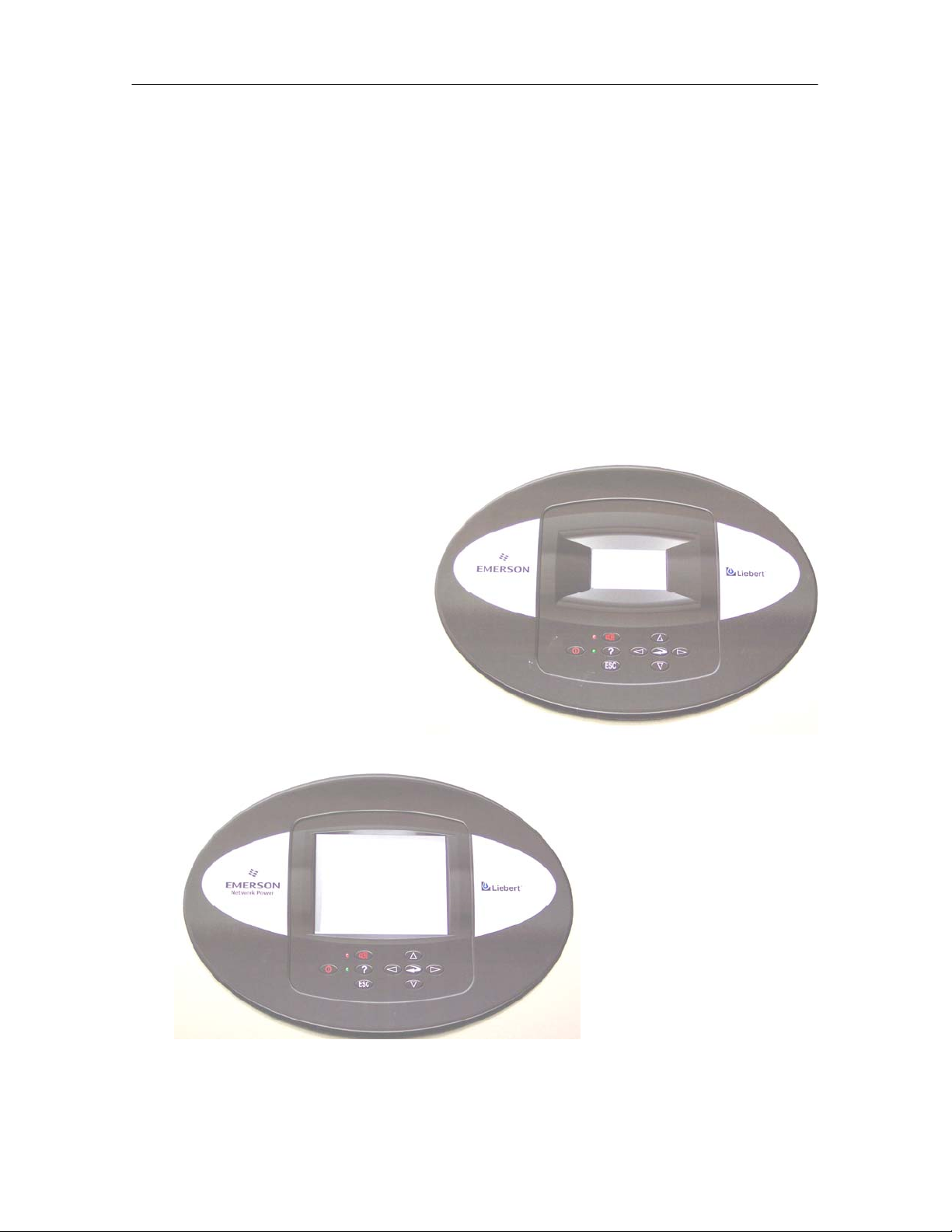
iCOM
Controls Training and Service Manual
Chapter 2
Programming Functions
The standard iCOM control is supplied with a front panel mounted small display
screen display which features a 128 x 64 dot matrix graphics. The display
provides both descriptive text readouts and two (2) menu icons. The optional
large screen display features a 320 x 240 dot matrix graphic display that shows
user and service icons as well as descriptive text and graphics. The information
provided visually on either of these displays is: room temperature and humidity,
temperature and humidity set points, alarm status and settings, event histories and
the current time. All programming functions will be done through the supplied
display.
Small Graphic Display
with Panel Mount Bezel
Optional Large Graphic
Display with Panel
Mount Bezel
52
Page 54

iCOM
Control Training and Service Manual
iCOM Display Components and Functions
The large display is shown for reference. The keypad and LEDs are identical on
all displays.
Liquid Crystal display
LED Status Indicators
Top LED is red or flashing red - alarm,
Bottom LED is amber (power on) or green (unit on) Keypad
iCOM Keyboard Layout:
The iCOM control screen displays text and icons for monitoring and programming
your Liebert unit and/ or network of units. The number of icons and the amount of
text shown depends upon the display type supplied on your unit. From the default
menu, the user menu may be accessed by pressing the enter key. When the user
selects an icon the various submenus, set points, status, thresholds and service
information is displayed. The following defines the various keyboard icons and
functions.
53
Page 55

iCOM
Controls Training and Service Manual
iCOM Keyboard Layout:
Icon Key Name Function
On/ Off Key Controls the operation state of the unit.
Alarm Key Silences the audible alarm.
Help Key Accesses the integrated help menus.
ESCape Key Returns to the previous display.
Enter Key Confirms all selections, icons and text.
Increase Key
(Up Arrow)
Decrease Key
(Down Arrow)
Left Arrow Key
Right Arrow
Key
Upper LED
Lower LED
Moves upward through the menu or increases the
value of the selected parameter.
Moves downward through the menu or decreases
the value of the selected parameter.
Navigates through text and selections of the
display.
Navigates through text and selections of the
display.
Blinking Red: Active, unacknowledged alarm
exists.
Solid Red: Active, acknowledged alarm exists.
Amber: Power available to the unit, unit NOT
operating.
Green: Power available to the unit, unit is
operating.
54
Page 56

iCOM
Control Training and Service Manual
iCOM Display Symbols/ Icons
The iCOM programming functions are separated into three (3) basic menus:
fan compressor freecooling maintenance
hot water el. heaters dehum hum
horn
• User Menu
• Service Menu
• Advanced Menu
When the desired icon has been selected, press the enter key. If the selected
menu item has submenus, they are now revealed. If there are no submenus, the
function or setting or command level text is displayed. User and Service menu
settings are readable without a password, changing the programmed values
requires a password. When a password is required to perform a programming
function, the iCOM displays a password prompt. Advanced menu setting requires
a password to read and program.
55
Page 57

iCOM
Controls Training and Service Manual
Programming Functions
Status Display
The unit display will show the unit operational mode(s), return air temperature/
humidity readings and if active present alarm conditions. The end user can select
from two (2) display types, graphical or simple.
System View Screen Graphic Unit View Screen Simple
The Large and Small Display’s have the ability to present information in two
formats; the Graphic format will show the set points and/or the actual values of
the return air temperature and humidity readings. The operational functions of the
components are displayed with an icon and a bar graph to indicate to amount of
the required function. The bottom of the screen will indicate date, time, on/off
status and events. The message area below will provide additional information and
provide some basic navigation help. The Simple format will reduce the amount of
graphics displayed and offers a not so busy display of the same information. The
displays will provide the System and Unit views
The end user can also select from dark background with white text or light
background with dark text.
Graphic Screen with reversed Contrast
56
Page 58

iCOM
Menu Screens ICON Symbols
Control Training and Service Manual
Menu Parameters Names
Level 1: User Level 2: Service Level 3: Advanced
Readable w/o password
PW required to program
1 Setpoints Setpoints Factory Settings
2 Spare Parts List Unit Diary
3 Events Log/ Status Report Standby Settings/ Lead-Lag
4 Graphics Maintenance/ Wellness Settings
5 View Network Diagnostics/ Service Mode
6 Set Alarms Set Alarms
7
8 Change Passwords
9 Various Sensors Sensor Calibration/ Sewtup
10
Readable w/o password
PW required to program
PW required to read
or program
11 Display Setup System/ Network Setup
12 Total Run Hours Options Setup
57
Page 59

iCOM
Controls Training and Service Manual
User Menu Icons and Descriptions:
Icon Name Descriptions
°C/ °F
% RH
SET
EVENT
LOG
Set Points
Spare Parts
List
Event Log
Graphic Data
Record
View Network
Set Alarms
To view and change temperature
and humidity set points
Displays the spare parts list of the
unit
Contains a log of the last 400
events
Displays the temperature and
humidity graphs
Shows the status of all connected
units
Allows the enabling, disabling and
setting of the alarm parameters
Available
Display
Small and
Large
Large
Small and
Large
Small and
Large
Large
Small and
Large
Sensor Data
Display Setup
Total Run
Hours
Sleep Mode
Service
Contacts
Shows readings for the standard
and optional sensors
Change the settings for display,
language, time and simple or
graphic display
Records the run time of all
components and allows for
setting the limits on run time
Allows for setback programming
for non-peak operation
Contains key contact information
for local service, including names
and phone numbers
Small and
Large
Small and
Large
Small and
Large
Small and
Large
Large
58
Page 60

iCOM
Control Training and Service Manual
Service Menu Icons and Descriptions:
Icon Name Descriptions
°C/ °F
% RH
SET
Set Points
Unit Diary
Standby
Settings
Maintenance/
Wellness
Settings
Diagnostic/
Service Mode
To view and change temperature
and humidity set points
Is a notepad containing notes
from the service person or
customer
Programs lead/ lag setup when
multiple units are connected
together
Allows programming of the
maintenance interval reminder,
maintenance messages, number
of unit starts and stops, time
since last maintenance
Allows for troubleshooting,
manual mode and viewing of the
analog and digital inputs
Available
Display
Small and
Large
Large
Small and
Large
Small and
Large
Small and
Large
Set Alarms
Sensor
Calibration/
Setup
System/
Network Setup
Options Setup
Service
Contacts
Allows the enabling, disabling and
setting of the alarm parameters
Allows for the calibration of the
various sensors
Allows for setup and unit-2-unit
communication for multiple units
Allows for the setup of component
operation
Contains key contact information
for local service, including names
and phone numbers
Small and
Large
Small and
Large
Large
Small and
Large
Small and
Large
59
Page 61

iCOM
Controls Training and Service Manual
Advanced Menu Icons and Descriptions:
Icon Name Descriptions
Factory
Settings
Change
Passwords
Factory configuration files. Do
Not Change Settings Consult
the Factory First
Allows the user to change the
various passwords
Display
Small and
Large
Small and
Large
Menu Parameters
All of the various parameters and program ranges are shown in tables located in
this chapter. The following sections highlight the various parameters and
programs in the iCOM control.
User Menu Parameters
The User menu displays the various unit operating values and status icons. The
factory default password to access the user menu items for programming is “149”.
The User Menu selections include the following choices in the order shown:
Available
• Set Point Parameters
• Spare Part List
• Event Log
• Graphics Log Parameters
• View Network Parameters
• Set Alarm Parameters
• Sensor Parameters
• Active Alarms
• Display Setup Parameters
• Total Run Hours
• Sleep Mode Timer Parameters
• Service Contacts Information
60
Page 62

iCOM
Control Training and Service Manual
User Menu: Set Point Parameters U100 series
Menu Line Parameter Default Range
U101 Password - U102 Temperature Setpoint 73ºF 41 - 104ºF
U103 Humidity Setpoint 50% 1 – 80%
U104 Humidity Control Type Yes Yes or No
U105 Supply Limit Disabled Disabled or Enabled
U106 Supply Limit Temp Value
41°F 41 - 77°F
U107
U108
U109
U110
U111
User Menu: Spare Parts List, Large Display Only
Parameter
Unit spare parts list
User Menu: Event Log
Parameter
Stores the last 400 events (messages, warnings and
alarms a that have occurred
61
Page 63

iCOM
Controls Training and Service Manual
User Menu: Graphics Parameters
Parameter Default Range
System Temperature Time Scale 24 Hours
8, 32 min or 1, 12, 24 hours
or 2, 4, 8, 16 days
System Temperature Graph Height 9ºF ±36ºF
System Humidity Time Scale 24 Hours
8, 32 min or 1, 12, 24 hours
or 2, 4, 8, 16 days
System Humidity Graph Height 10% ±20%
Unit Temperature Time Scale 24 Hours
8, 32 min or 1, 12, 24 hours
or 2, 4, 8, 16 days
Unit Temperature Graph Height 9ºF ±36ºF
Unit Humidity Time Scale 24 Hours
8, 32 min or 1, 12, 24 hours
or 2, 4, 8, 16 days
Unit humidity Graph Height 10% ±20%
User Menu: View Network Parameters
Parameter
User to select and view status of all units connected
together (only Large Display)
62
Page 64
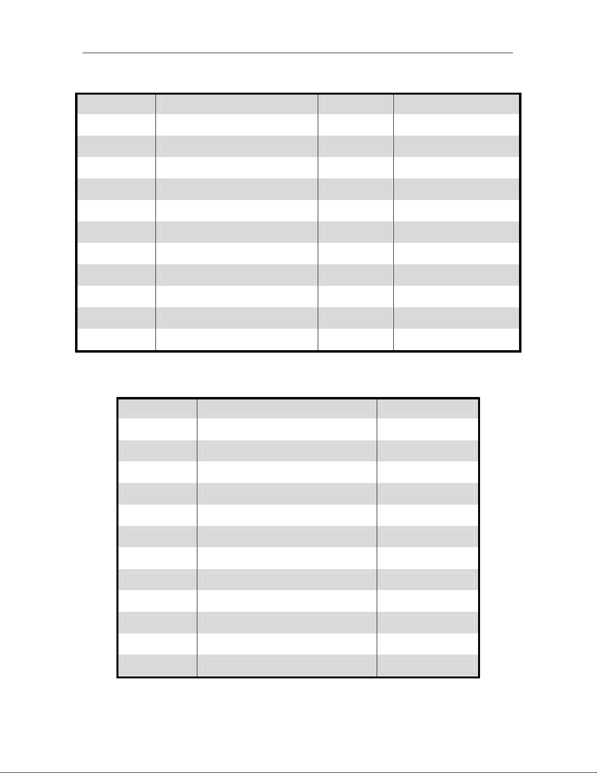
iCOM
Control Training and Service Manual
User Menu: Set Alarm Parameters U200 series
Menu Line Parameter Default Range
U201 Password - U202 Return Sensor Alarms Enabled Enabled or Disabled
U203 High Return Temperature 80ºF 33 - 210ºF
U204 Low Return Temperature 60ºF 33 - 210ºF
U205 High Return Humidity 60% 1 – 99%
U206 Low Return Humidity 40% 1 – 99%
U207 Sensor A Alarms Disabled Disabled or Enabled
U208 High Temperature Sensor A 90ºF 33 - 210ºF
U209 Low Temperature Sensor A 55ºF 33 - 210ºF
U210 High Humidity Sensor A 70% 1 - 99%
U211 Low Humidity Sensor A 30% 1 - 99%
User Menu: Sensor Data U300 series: Page 1 of 2
Menu Line Parameter Range
U301 Actual Temperature Setpoint 41 – 104ºF
U302 Actual Humidity Setpoint 20 – 80%
U303 Optional Sensor A Temperature 32 - 122ºF
U304 Optional Sensor A Humidity 20 – 80%
U305 Optional Sensor B Temperature 32 - 122ºF
U306 Optional Sensor B Humidity 20 – 80%
U307 Optional Sensor C Temperature 32 - 122ºF
U308 Optional Sensor C Humidity 20 – 80%
U309 Freecooling Fluid Temperature 4 - 113ºF
U310 DigiScroll 1 Temperature 84 - 313ºF
U311 DigiScroll 2 Temperature 84 - 313ºF
U312
Freecooling Status Off, Start, On
63
Page 65

iCOM
Controls Training and Service Manual
User Menu: Sensor Data U300 series: Page 1 of 2
Menu Line Parameter Time/ Value
U313 Daily High Temperture
U314 Daily Low Temperature
U315 Daily High Humidity
U316 Daily Low Humidity
User Menu: Active Alarms Parameters
Parameter
User to view all active alarms of all units connected
together (only Large Display)
User Menu: Display Setup Parameters U400 series
Menu Line Parameter Default Range
U401 Language English English . . .
U402 Date (Month/Day/Year) MM/ DD/ YYYY MM/ DD/ YYYY
U403 Time (Hrs:Min:Sec) - HH/ MM/ SS
U404 Temperature Indication ºF ºF/ ºC
U405 Display Contrast 80% 0 – 100%
U406 Buzzer Frequency On at 80% On, Off, 0 – 100%
U407
Backlite Off After x
Hours
5 minute 5 min – 12 hours
U408 Screen Simple Simple or Graphical
U409 Display Shows Set + Act Set + Act, Set, Act
U410 Display Colors Normal Normal or Inverted
yyyy-mm-dd
U411 Date Format dd.mm.yyyy
dd.mm.yyyy
mm/dd/yyyy
64
Page 66
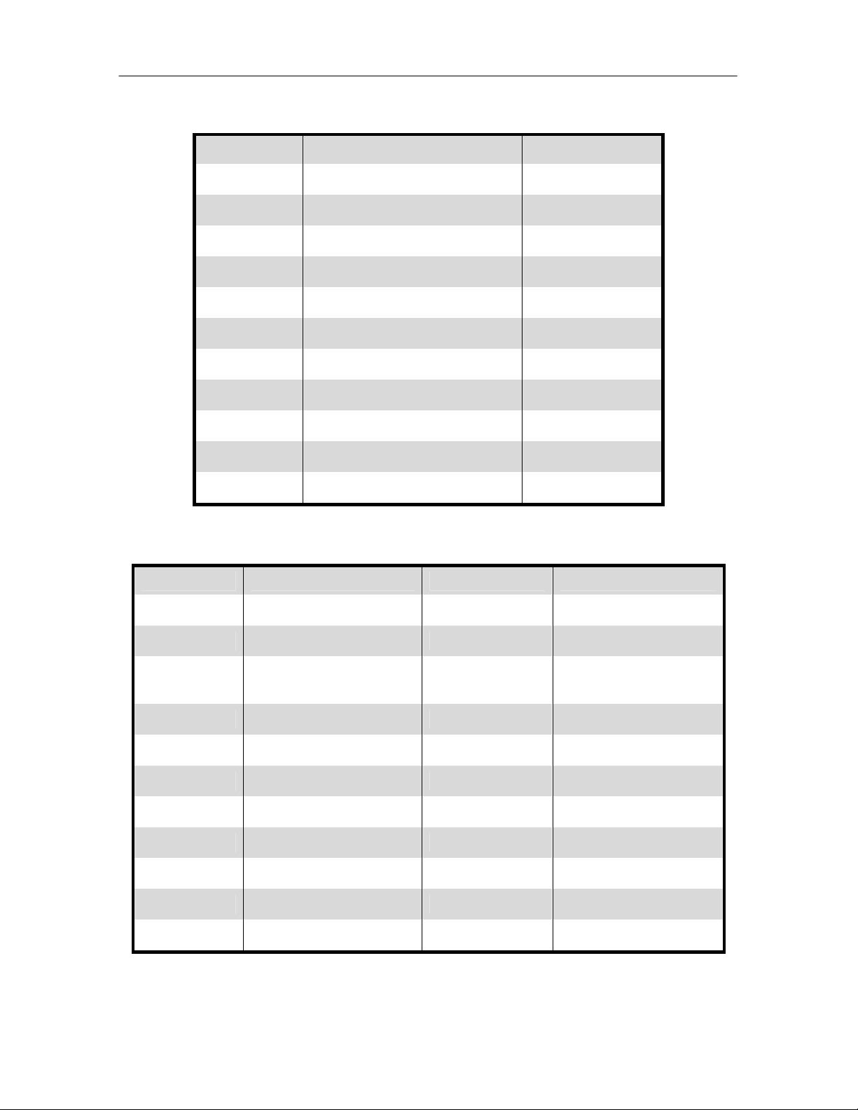
iCOM
Control Training and Service Manual
User Menu: Total Run Hours Parameters U500 series
Menu Line Parameter Range (Hours)
U501 - Actual
U502 Fan motor(s) 0 - 32000
U503 Compressor 1 0 - 32000
U504 Compressor 2 0 - 32000
U505 Chilled Water/ Free Cool 0 - 32000
U506 Hot Gas / Hot Water 0 - 32000
U507 Electrical Heater 1 0 - 32000
U508 Electrical Heater 2 0 - 32000
U509 Electrical Heater 3 0 - 32000
U510 Humidifier 0 - 32000
U511 Dehumidification 0 - 32000
User Menu: Sleep Mode Parameters U600 series
Menu Line Default Range Parameter
U601 Password - U602 Sleep On - -
U603
Mon, Tue, Wed, Thu,
Fri, Sat, Sun
No No or Yes
U604 Sleep Every Day (1) - U605 From / To 00:00 / 00:00 Time (hh:mm)
U606 Sleep Every Day (2) - U607 From / To 00:00 / 00:00 Time (hh:mm)
U608
U609 Timer Mode No No, Yes, Auto
U610 Timer Mode Type System Off Sys off, Deadband
U611 Dead Band 4ºF 4 - 27ºF
65
Page 67

iCOM
User Menu: Service Contacts U700 series
Controls Training and Service Manual
Menu Line Parameter Range
U701
U702
U703 Address Line 1 Text String
U704 Address Line 2 Text String
U705 Address Line 3 Text String
U706 Address Line 4 Text String
66
Page 68

iCOM
Control Training and Service Manual
Service Menu Parameters
The Service menu display allows the user to customize the various unit settings for
site specific operation. The factory default password to access the service menu
items for programming is “501”. The Service Menu selections include the following
choices in the order shown:
• Set Point Parameters
• Unit Diary
• Standby Settings Parameters
• Maintenance / Wellness Setting Parameters
• Diagnostic / Service Mode Parameters
• Set Alarm Parameters
• Sensor Calibration / Setup Parameters
• System / Network Setup Parameters
• Operations Setup Parameters
• Service Contacts Parameters
Service Menu: Set Point Parameters S100 series: Page 1 of 2
Menu Line Parameter Default Range
S101 Password - S102 Temperature Setpoint 73ºF 41 - 104ºF
S103 Humidity Setpoint 50% 1 – 80%
S104 Humidity Control Type Yes Yes or No
S105 Supply Limit Disabled Disabled or Enabled
S106 Supply Limit Temp Value 41ºF 41 - 77ºF
S107 Autoset Enable Yes Yes or No
S108 Temperature Proportional Band 7ºF 2 - 54ºF
S109 Temperature Integration Time 0 0 – 5 minutes
S110 Temperature Deadband 0 0 - 36ºF
S111 Short Cycle Control Yes Yes or No
67
Page 69

iCOM
Controls Training and Service Manual
Service Menu: Set Point Parameters S100 series: Page 2 of 2
Menu Line Parameter Default Range
S112 Password - S113 Humidity Proportional Band 10% 1 – 20%
S114 Humidity Integration Time 0 0 – 5 minutes
S115 Humidity Deadband 0 0 – 50%
S116 DT Between Room / FC Type Disable
Disable, Contact,
Value
S117 DT Between Room Air / FC Fluid 8ºF 0 - 36ºF
S118 Minimum CW Temp Disable Enable / Disable
S119 Minimum CW Temp Value 45ºF 32 - 68ºF
S120
S121
S122
Service Menu: Unit Diary Log
Parameter
Displays changes to the unit as performed and entered by
the service person or customer
68
Page 70
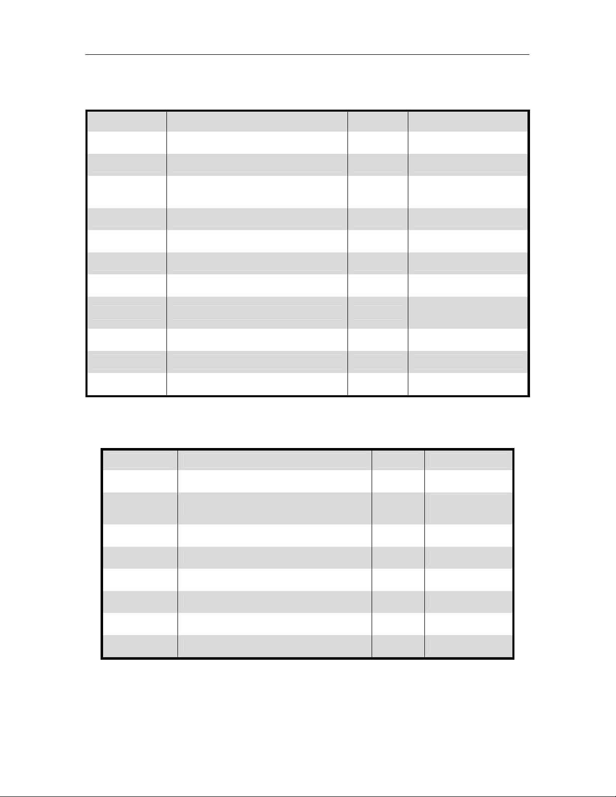
iCOM
Control Training and Service Manual
Service Menu: Standby Setting / Lead-lag Parameters S500 series
Menu Line Parameter Default Range
S501 Password - S502 Number of Standby Units 0 0 – 15
S503 Rotation Frequency No
No, Daily, Every M,
T, W, Th, F, S, Su
S504 Rotate at (hour) 0 0 – 23
S505 Rotate at (minute) 0 0 – 59
S506 Rotate by 1 1 – 8
S507 Perform one rotation - No or Yes
S508 Cascade units No
No, Yes, Cool,
Temp
S509 Start All Standby Units by HT No No or Yes
S510
S511
Service Menu: General Settings Maintenance / Wellness Parameters S000
series: Page 1 of 8
Menu Line Parameter Default Range
S001 Password - S002 Maintenance Frequency Per Year 1
0 – 12 per
year
S003 Max Bonus 0 0 – 12
S004 Max Penalty 0 0 – 12
S005 Last Maintenance - Date
S006 Service Engineer - Name
S007 Confirm PM - No or Yes
S008 Calculated Next Maintenance - Date
69
Page 71

iCOM
Controls Training and Service Manual
Service Menu: Fan Settings Maintenance / Wellness Parameters: Page 2 of 8
Menu Line Parameter Default Range
S012 Password - S013 Number of Starts - 0 – 32000
S014 Run Hours - 0 – 32000
S015 Average Working Time - 0 – 999 minutes
S016 Starts per Day Optimum 1 1 – 240
S017 Starts per Day Worst 24 1 – 240
S018 Number of Alarms - 0 – 32000
S019 Actual Bonus - 0 - 12
Service Menu: Compressor 1 Settings Maintenance / Wellness Parameters:
Page 3 of 8
Menu Line Parameter Default Range
S023 Password - S024 Number of Starts - 0 – 32000
S025 Run Hours - 0 – 32000
S026 Average Working Time - 0 – 999 minutes
S027 Starts per Day Optimum 12 1 – 240
S028 Starts per Day Worst 240 1 – 240
S029 Number of HP Alarms - 0 – 32000
S030 Number of LP Alarms - 0 – 32000
S031 Number of OL Alarms - 0 – 32000
S032 Number of DS HT Alarms - 0 - 32000
S033 Actual Bonus - 0 - 12
70
Page 72
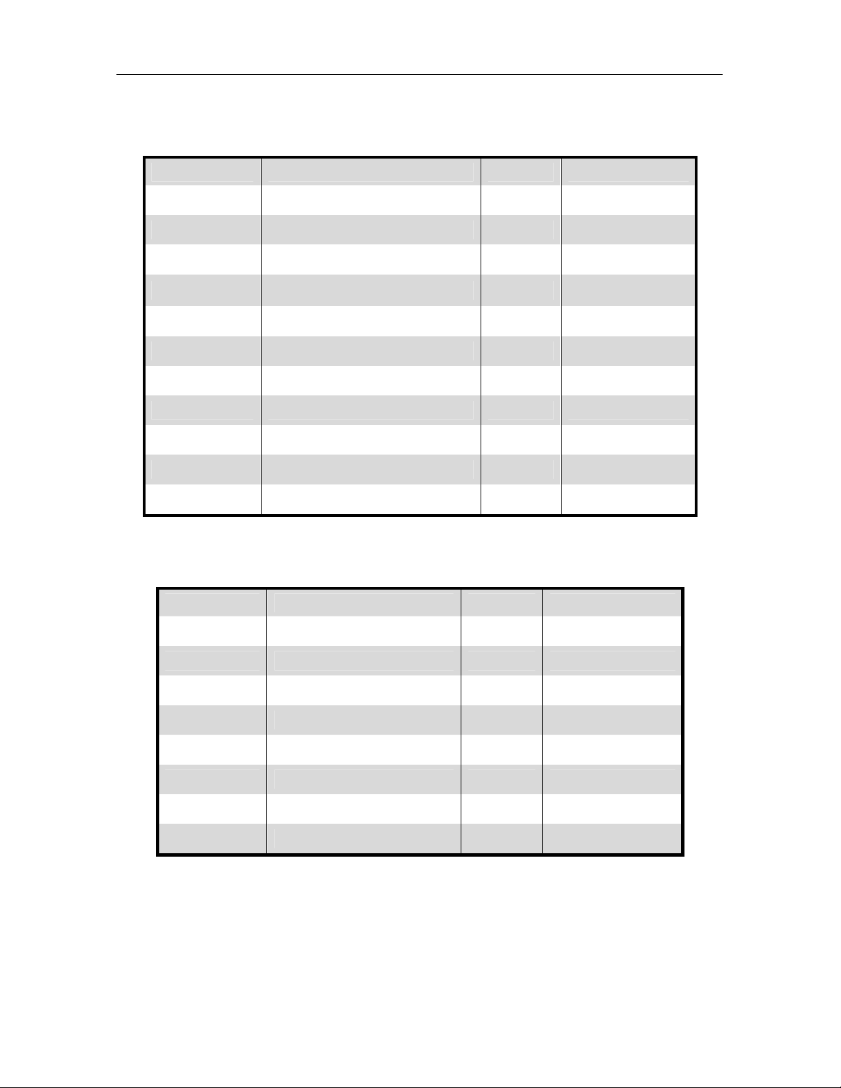
iCOM
Service Menu: Compressor 2 Settings Maintenance / Wellness Parameters:
Page 4 of 8
Menu Line Parameter Default Range
S034 Password - S035 Number of Starts - 0 – 32000
S036 Run Hours - 0 – 32000
S037 Average Working Time - 0 – 999 minutes
S038 Starts per Day Optimum 12 1 – 240
S039 Starts per Day Worst 240 1 – 240
S040 Number of HP Alarms - 0 – 32000
S041 Number of LP Alarms - 0 – 32000
S042 Number of OL Alarms - 0 – 32000
Control Training and Service Manual
S043 Number of DS HT Alarms - 0 - 32000
S044 Actual Bonus - 0 - 12
Service Menu: Electric Heater 1 Settings Maintenance / Wellness
Parameters: Page 5 of 8
Menu Line Parameter Default Range
S045 Password - S046 Number of Starts - 0 – 32000
S047 Run Hours - 0 – 32000
S048 Average Run Time - 0 – 999 minutes
S049 Starts per Day Optimum 24 1 – 240
S050 Starts per Day Worst 240 1 – 240
S051 Number of Alarms - 0 – 32000
S052 Actual Bonus - 0 - 12
71
Page 73

iCOM
Controls Training and Service Manual
Service Menu: Electric Heater 2 Settings Maintenance / Wellness
Parameters: Page 6 of 8
Menu Line Parameter Default Range
S056 Password - S057 Number of Starts - 0 – 32000
S058 Run Hours - 0 – 32000
S059 Average Run Time - 0 – 999 minutes
S060 Starts per Day Optimum 24 1 – 240
S061 Starts per Day Worst 240 1 – 240
S062 Number of Alarms - 0 – 32000
S063 Actual Bonus - 0 - 12
Service Menu: Electric Heater 3 Settings Maintenance / Wellness
Parameters: Page 7 of 8
Menu Line Parameter Default Range
S067 Password - S068 Number of Starts - 0 – 32000
S069 Run Hours - 0 – 32000
S070 Average Run Time - 0 – 999 minutes
S071 Starts per Day Optimum 24 1 – 240
S072 Starts per Day Worst 240 1 – 240
S073 Number of Alarms - 0 – 32000
S074 Actual Bonus - 0 - 12
72
Page 74

iCOM
Control Training and Service Manual
Service Menu: Humidifier Settings Maintenance / Wellness Parameters:
Page 8 of 8
Menu Line Parameter Default Range
S078 Password - S079 Number of Starts - 0 – 32000
S080 Run Hours - 0 – 32000
S081 Average Run Time - 0 – 999 minutes
S082 Starts per Day Optimum 24 1 – 240
S083 Starts per Day Worst 240 1 – 240
S084 Number of Alarms - 0 – 32000
S085 Actual Bonus - 0 - 12
Service Menu: Diagnostics / Service Mode S300 series: Page 1 of 5
Menu Line Parameter Range
S301 Password S302 Manual Mode Yes or No
S303 Motor(s) Off or On
S304 Compressor 1 Off or On
S305 Compressor 1 Capacity Off or On
S306 Compressor 1 Cycle Ramp 0-100%
S307 Compressor 1 LLSV Off or On
S308 Compressor 2
S309 Compressor 2 Capacity Off or On
S310 Compressor 2 Cycle Ramp 0 – 100%
S311 Compressor 2 LLSV
73
Page 75

iCOM
Controls Training and Service Manual
Service Menu: Diagnostics / Service Mode: Page 2 of 5
Menu Line Parameter Range
S312 Password S313 HP 1 Alarm Counter 0
S314 HP 2 Alarm Counter 0
S315 HT 1 Alarm Counter 0
S316 HT 2 Alarm Counter 0
S317
S318
S319
S320 Electric Heat 1(or HG/ HW) Off or On
S321 Heat 2 (or E.Heat 1) Off or On
S322 Heat 3 (or E.Heat 2) Off or On
Service Menu: Diagnostics / Service Mode: Page 3 of 5
Menu Line Parameter Range
S323 Password S324 Humidifier Fill Off or On
S325 Humidifier Off or On
S326 Alarm Relay Off or On
S327 FC Relay Off or On
S328 3P Actuator Open Off or On
S329 3P Actuator Close Off or On
S330 Analog Out 1 0 – 100%
S331 Analog Out 2 0 – 100%
S332 Analog Out 3 0 – 100%
S333 Analog Out 4 0 – 100%
74
Page 76
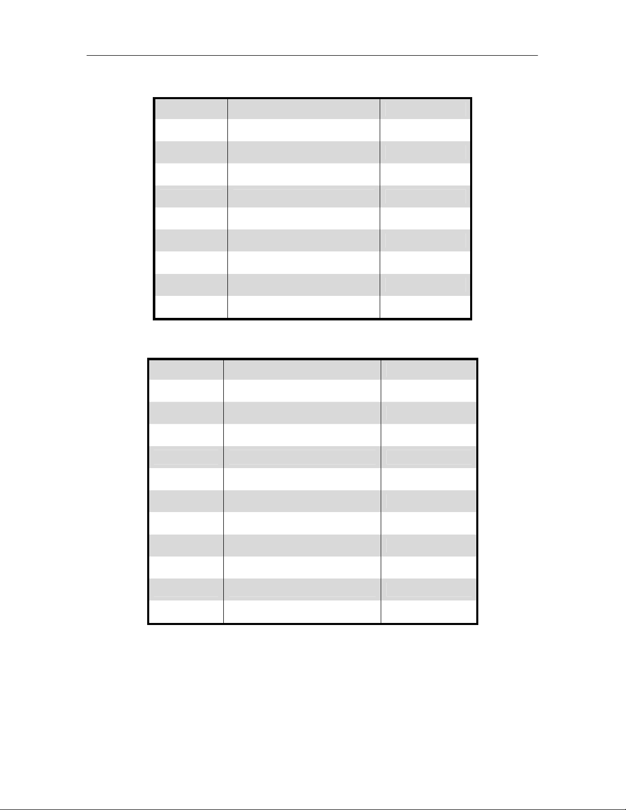
iCOM
Control Training and Service Manual
Service Menu: Diagnostics / Service Mode: Page 4 of 5
Menu Line Parameter Range
S334 Password S335 Status Remote Shutdown Off or On
S336 Status Airflow Loss OK or Active
S337 Status Motor Overload OK or Active
S338 Status Filter OK or Active
S339 Status Customer Input 1 OK or Active
S340 Status Customer Input 2 OK or Active
S341 Status Customer Input 3 OK or Active
S342 Status Customer Input 4 OK or Active
Service Menu: Diagnostics / Service Mode: Page 5 of 5
Menu Line Parameter Range
S345 Password S346 Status HP1 OK or Active
S347 Status LP1 OK or Active
S348 Status C1 OL OK or Active
S349 Status HP2 OK or Active
S350 Status LP2 OK or Active
S351 Status C2 OL OK or Active
S352 Status Humidifier Problem OK or Active
S353 Status DT2 Off or On
S354 Status Min CW Off or On
S355
75
Page 77

iCOM
Controls Training and Service Manual
Service Menu: Set Alarm Parameters S200 series: Page 1 of 6
Menu Line Parameter Default Range
S201 Password - S202 Return Sensor Alarms Enabled Disabled or Enabled
S203 High Return Temperature 80ºF 34 - 210ºF
S204 Low Return Temperature 65ºF 34 - 210ºF
S205 High Return Humidity 60% 1 – 99%
S206 Low Return Humidity 40% 1 – 99%
S207 Sensor A Alarms Disabled Disabled or Enabled
S208 High Temperature Sensor A 90ºF 34 - 210ºF
S209 Low Temperature Sensor A 55ºF 34 - 210ºF
S210 High Humidity Sensor A 70% 1 – 99%
S211 Low Humidity Sensor A 30% 1 – 99%
Service Menu: Set Alarm Parameters: Page 2 of 6
Menu Line Parameter Default Range
S212 Password - S213 Customer Input 1 Water alarm See note
S214 Customer Input 1 Active When Closed Open or Closed
S215 Customer Input 2 Water alarm See note
S216 Customer Input 2 Active When Closed Open or Closed
S217 Customer Input 3 Water alarm See note
S218 Customer Input 3 Active When Closed Open or Closed
S219 Customer Input 4 Water alarm See note
S220 Customer Input 4 Active When Closed Open or Closed
S221 Warning Activates Alarm Relay Yes Yes or No
S222 Reset Disabled Alarms No Yes or No
Note: Customer Inputs 1, 2, 3 and 4 messages may be selected from Smoke
Detected, Water Alarm, Condensate Pump Alarm, Flow Alarm, Standby Pump,
Standby Unit.
76
Page 78

iCOM
Control Training and Service Manual
Service Menu: Set Alarm Parameters: Page 3 of 6
Menu Line Parameter
S223 Password
S224 DELAY EN-DIS TYPE
S225 Main Fan Overload 10 Sec En Alarm
S226 Loss of Airflow 10 Sec En Alarm
S227 Clogged Filters 60 Sec En Warning
S228 High Room Temperature 10 Sec En Warning
S229 Low Room Temperature 10 Sec En Warning
S230 High Room Humidity 10 Sec En Warning
S231 Low Room Humidity 10 Sec En Warning
S232 High Temp Sensor A 10 Sec En Warning
S233 Low Temp Sensor A 10 Sec En Warning
S234 High Humid Sensor A 10 Sec En Warning
S235 Low Humid Sensor A 10 Sec En Warning
Service Menu: Set Alarm Parameters: Page 4 of 6
Menu Line Parameter
S236 Password
S237 DELAY EN-DIS TYPE
S238 Comp 1 Overload 10 Sec En Alarm
S239 Comp 2 Overload 10 Sec En Alarm
S240 Comp 1 High Pressure - En Alarm
S241 Comp 1 High Pressure - En Alarm
S242 Comp 1 Low Pressure - En Alarm
S243 Comp 2 Low Pressure - En Alarm
S244 Comp 1 Pumpdown Fail - En Alarm
S245 Comp 2 Pumpdown Fail - En Alarm
S246 Dig Scroll1 High Temp - En Alarm
S247 Dig Scroll2 High Temp Alarm
77
Page 79

iCOM
Service Menu: Set Alarm Parameters: Page 5 of 6
Controls Training and Service Manual
Menu Line Parameter
S249 Password
S250 DELAY EN-DIS TYPE
S251 Working Hours Exceeded - En Warning
S252 Smoke Detected 5 Sec En Alarm
S253 Water Under Floor 5 Sec En Alarm
S254 Cond Pump-High Water 5 Sec En Alarm
S255 Loss of Flow 5 Sec En Alarm
S256 Standby Glycol Pump On 5 Sec En Alarm
S257 Standby Unit On 5 Sec En Alarm
S258 Humidifier Problem 5 Sec En Alarm
S259 No Connection w/ Unit 1 - En Alarm
S260 Unit X Disconnected - En Alarm
Service Menu: Set Alarm Parameters: Page 6 of 6
Menu Line Parameter
S262 Password
S263 DELAY EN-DIS TYPE
S264 Customer Input 1 5 Sec En Alarm
S265 Customer Input 2 5 Sec En Alarm
S266 Customer Input 3 5 Sec En Alarm
S267 Customer Input 4 5 Sec En Alarm
S268 Call Service 5 Sec En Message
S269 High Temperature 5 Sec En Message
S270 Loss of Air Blower 1 5 Sec En Alarm
S271 Reheat Lockout 5 Sec En Message
S272 Humidifier Lockout 5 Sec En Message
S273 Humid + Reheat Lockout 5 Sec En Message
S274 Compressor(s) Lockout 5 Sec En Message
78
Page 80

iCOM
Service Menu: Sensor Calibration/ Setup Parameters S600 series:
Page 1 of 3
Menu Line Parameter Range
S601 Password S602 Return temperature ±17ºF
S603 Calibrated return temperature 32 - 122ºF
S604 Return humidity ±9.9%
S605 Calibrated return humidity 20 – 80%
S606 Digital Scroll 1 NTC ±17ºF
S607 Calibrated digital scroll 1 NTC 84 – 313ºF
S608 Digital Scroll 2 NTC ±17ºF
S609 Calibrated digital scroll 2 NTC 84 - 313ºF
Control Training and Service Manual
Service Menu: Sensor Calibration/ Setup Parameters: Page 2 of 3
Menu Line Parameter Range
S612 Password S613 Temperature sensor A ±17ºF
S614 Calibrated temperature sensor A 32 - 122ºF
S615 Humidity sensor A ±9.9%
S616 Calibrated humidity sensor A 20 – 80%
S617 Temperature sensor B ±17ºF
S618 Calibrated temperature sensor B 32 - 122ºF
S619 Humidity sensor B ±9.9%
S620 Calibrated humidity sensor B 20 – 80%
79
Page 81
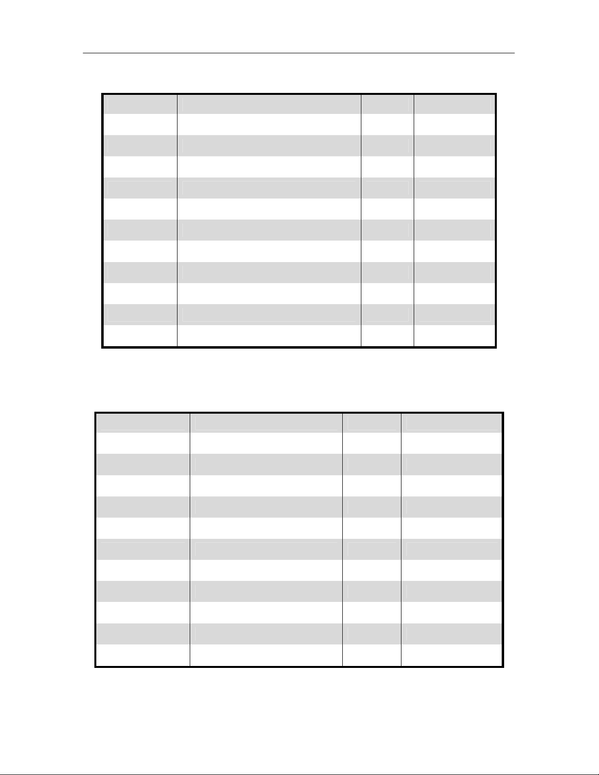
iCOM
Controls Training and Service Manual
Service Menu: Sensor Calibration/ Setup Parameters: Page 3 of 3
Menu Line Parameter Default Range
S623 Password S624 Glycol sensor PTC or NTC NTC NTC or PTC
S625 Glycol sensor - ±17ºF
S626 Calibrated glycol sensor - 4 – 113ºF
S627 Supply sensor PTC or NTC NTC NTC or PTC
S628 Supply sensor - ±17ºF
S629 Calibrated supply sensor - 32 - 122ºF
S630 Temperature sensor C - ±17ºF
S631 Calibrated temperature sensor C - 32 - 122ºF
S632 Humidity sensor C - ±9.9%
S633 Calibrated humidity sensor C - 20 – 80%
Service Menu: System / Network Setup Parameters Series S800:
Page 1 of 2, System View
Menu Line Function Default Range
S801 Password - S802 Number of connected units - 1 – 16
S803 Teamwork mode No No, 1, 2
S804
S805 U2U group - 1 - 99
S806
S807
S808
S809 Configuration Safe Status No No, Save, Load
S810 Network Safe Status - No, Save, Load
S811 SW version: -
80
Page 82
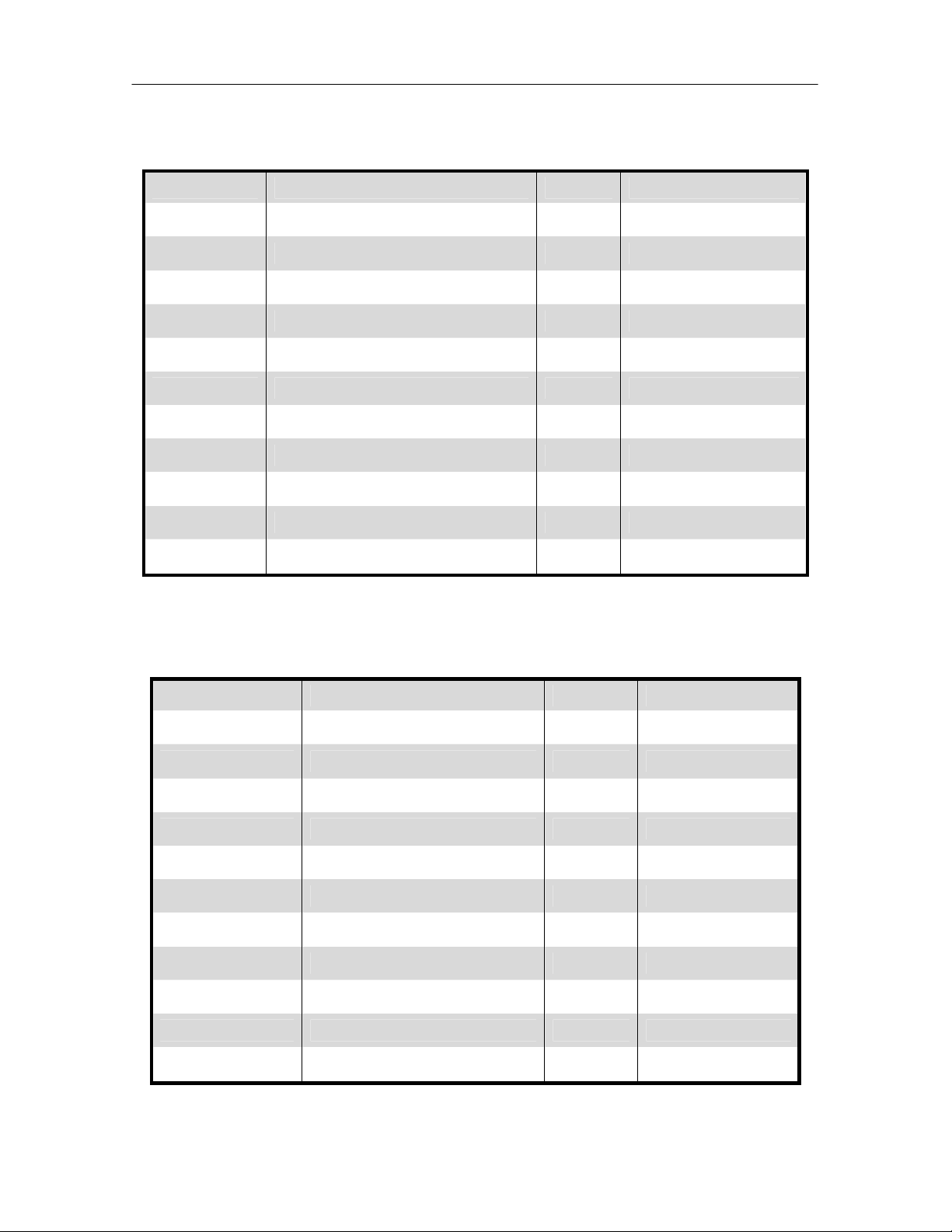
iCOM
Control Training and Service Manual
Service Menu: System / Network Setup Parameters Series S800:
Page 2 of 2, System View
Menu Line Function Default Range
S812 Password - S813 IP Address - IP Address
S814 Netmask - Netmask Range
S815 Gateway - Gateway Range
S816 MAC - MAC Range
S817 U2U Protocol - S818 U2U Address - 33 - 64
S819 - S820 -
S821 Bootloader Variables Status - Changed, Updating
S822 Bootloader Variables Control - No, Save + Reboot
Service Menu: System / Network Setup Parameters Series S800:
Page 1 of 2, Unit View
Menu Line Function Default Range
S823 Password -
S824 Monitoring Address 3
S825
S826 U2U Group 1 – 99
S827 Unit Name Unit 6 Digits
S828
S829
S830
S831 Configuration Safe Status No No, Save, Load
S832 Network Safe Status No No, Save, Load
S833 SW version: -
81
Page 83
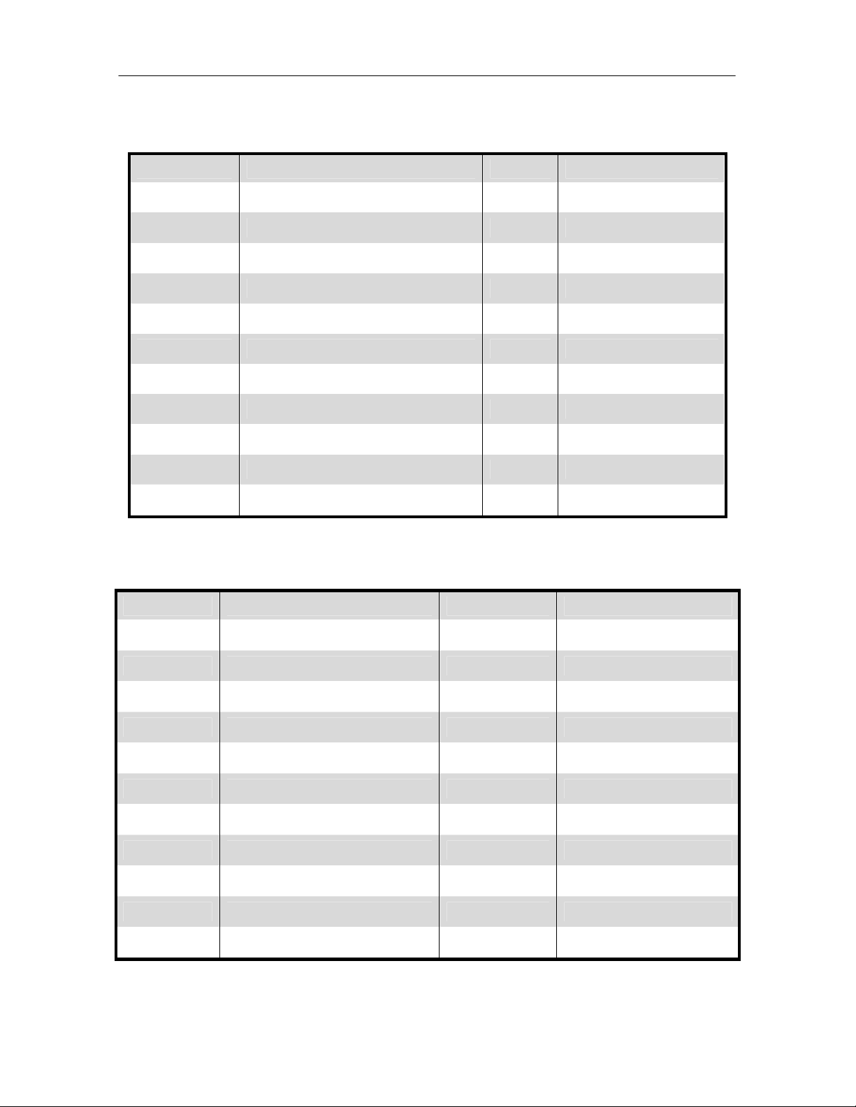
iCOM
Controls Training and Service Manual
Service Menu: System / Network Setup Parameters Series S800:
Page 2 of 2, Unit View
Menu Line Function Default Range
S834 Password -
S835 Monitoring Protocol - S836 IP Address - IP Range
S837 Netmask - Netmask Range
S838 Gateway - Gateway Range
S839 MAC - MAC Range
S840 U2U Protocol - 33 - 64
S841 U2U Address - S842 -
S843 Bootloader Variables Status - Changed, Updating
S844 Bootloader Variables Control - No, Save + Reboot
Service Menu: Option Setup Parameters S400 series: Page 1 of 2
Menu Line Function Default Range
S401 Password - S402 Compressor Sequence Auto 1, 2, Auto
S403 Low Pressure Delay (WSK) 3 0 – 5 Minutes
S404 Actual LP1 Pressure - 14.5 – 87.0 psiA
S405 Actual LP2 Pressure - 14.5 – 87.0 psiA
S406 Electric Stages - 0, 1, 2, 3
S407 Hot Water Heat On / Off No No or Yes
S408 Hot Gas Heat No No, Comp. 1, Comp. 2
S409 Total Heat Stages No 0, 1, 2, 3l
S410 3P Actuator Runtime 165 Seconds 50 – 400 seconds
S411 3P Actuator Direction Direct Direct or Reverse
82
Page 84

iCOM
Control Training and Service Manual
Service Menu: Option Setup Parameters S400 series:: Page 2 of 2
Menu Line Function Default Range
S412 Password - S413 Humidification Enabled Yes Yes or No
S414 Infrared Flush Rate 150% 110 – 500%
S415 Dehumidification Enabled Yes No or Yes
S416 Electric Reheat Operation No No, Normal, Delayed
S417 Single Unit Auto Restart 5 Seconds 0 – 999 seconds
S418 On – Off Enabled Yes Yes or No
S419
S420 CW Flush No No, 1 – 99 Hours
S421 Freecooling Flush No No, 1 – 99 Hours
S422 Hot Water Flush No No, 1 – 99 Hours
Service Menu: Service Contacts Parameters S700 series:
Menu Line Function Default Range
S701 Password - -
S702 Country USA None, United States
S703 Address line 1 - Text-string
S704 Address line 2 - Text-string
S705 Address line 3 - Text-string
S706 Address line 4 - Text-string
83
Page 85
iCOM
Controls Training and Service Manual
Advanced Menu Parameters
The Advanced menu displays allows the service technician to set the unit
configuration code and to customize the various unit settings for site-specific
operation. The factory default password to access the advanced menu items for
programming is “221”. The Advance Menu selections include the following
choices in the order shown:
• Factory Settings
• Access Levels
Advanced Menu: Factory Settings Parameters A001 series: Page 1 of 6
Menu Code Parameter Range
A001 Password A002
A003
A004
A005
A006
A007
A008
A009
A010
A011
Unit field code (R) (01 – 06)
Set code (W) (01 – 06)
Unit field code (R) (07 – 12)
Set code (W) (07 – 12)
Unit field code (R) (13 – 18)
Set code (W) (13 – 18)
No
Unit Code Control
Unit Code Status
Exception List Control No, Load
Exception List Status
Load+Execute
Save+Execute
No
Load+Execute
Save+Execute
No
Load+Execute
Save+Execute
84
Page 86

iCOM
Advanced Menu: Factory Settings Parameters A100 series: Page 2 of 6
Menu Code Function Default Range
A101 Password - A102 Refrigerant Type R22 R22, R407C
A103 Main Fan Overload Shut down Shut down, Disable
A104 Loss of Airflow Shut down Shut down, Disable
A105 Number of Compressors 2 0, 1, 2
A106 Compressor Delay Time 0 0 - 120 Sec
Control Training and Service Manual
A107
A108
A109 Pump Down Yes No, Yes
A110 Capacity Control Type Unloader
Advanced Menu: Factory Settings Parameters A100 series: Page 3 of 6
Menu Code Parameter Default Range
A112 Password - A113 Digi Scroll Cycle 15 No, 10 - 30 Sec
A114
A115 Digi Scroll Switchback 250°F 33 - 392°F
A116
Compressor Minimum
On Time
Compressor Minimum
Off Time
High Temperature Digi
Scroll
Low Pressure Device
Type
3 Min 0 - 5 Min
3 Min 0 - 5 Min
No, Unloader, HGBP,
Digital, Digital + TH
268°F 33 - 392°F
Analog Analog, Switch
A117
A118
Low Pressure Threshold
Phase 1
Low Pressure Threshold
Phase 2
* See Note 1 0.0 - 145 psiA
* See Note 2 0.0 - 145 psiA
85
Page 87

iCOM
Advanced Menu: Factory Settings Parameters: Page 4 of 6
Controls Training and Service Manual
Menu Code Parameter Default Range
A123 Password - A124 LP1 Sensor 10% 0 - 100%
A125
A126 Actual LP1 Signal - 0 - 100%
A127 LP2 Sensor 10% 0 - 100%
A128
A129 Actual LP2 Signal - 0 - 100%
A130 Pumpdown Cutout 35 psiA 0.0 - 145 psiA
A131 Pumpdown Recycle 80 psiA 0.0 - 145 psiA
A132
Advanced Menu: Factory Settings Parameters A100 series: Page 5 of 6
Menu Code Parameter Default Range
A134 Password - A135
LP1 Signal 150 psiA -87.0 to +725 psiA
LP2 Signal 150 psiA -87.0 to +725 psiA
Heat Rejection Control
Type
Fan Speed
Fan Speed /
Lee-Temp / Glycol
A136 CW flush Duration 0 No, 1 - 3 min
A137 Freecooling
A138
A139 Freecooling Flush Duration 0 No, 1 - 3 min
A140 Freecooling Flush Starts R5 Yes No, Yes
A141 CO + FC simultaneously Yes No, Yes
A142
A143 Hot water flush duration 0 No, 1 - 3 min
No
No, Yes
86
Page 88

iCOM
Advanced Menu: Factory Settings Parameters: Page 6 of 6
Menu Code Parameter Default Range
A145 Password - -
Control Training and Service Manual
A146 Humidifier Model
A147
A148 Prefill Time
A149 Fill Time
A150
A151
A152 Analog Output 1 Not used
A153 Analog Output 2 Not used
A154 Analog Output 3 Not used
A155 Analog Output 4 Not used
Note 1: LP threshold Phase 1 (A117):
If condenser ctrl (A132) = fan speed then setting is 50 psiA ; otherwise 75 psiA.
If the condenser control setting changes, the setting for A117 will be updated
automatically. If any of the sources (Refrigerant, Freecooling, Hotwater) changes,
the setting for A118 will be updated automatically.
Note 2: LP threshold Phase 1 (A118):
R22 (A102) + NO FC (A137) + NO Hotwater (S408) = 63 psiA
R22 (A102) + YES FC (A137) + NO Hotwater (S408) = 68 psiA
R22 (A102) + NO FC (A137) + YES Hotwater (S408) = 75 psiA
R22 (A102) + YES FC (A137) + YES Hotwater (S408) = 75 psiA
R407c (A102) + NO FC (A137) + NO Hotwater (S408) = 70 psiA
R407c (A102) + YES FC (A137) + NO Hotwater (S408) = 75 psiA
R407c (A102) + NO FC (A137) + YES Hotwater (S408) = 83 psiA
R407c (A102) + YES FC (A137) + YES Hotwater (S408) = 83 psiA
Note 3: The following components may be controlled with the Analog Outputs and
labeled as: Hot Water Reheat, 3P Valve, Fan Speed, Cooling, Cooling 1, Cooling
2, Heating and Not Used.
Humidity in Last
xx Hours
Humidifier On
Time
Dehum with
Compressor
No
15hr 1 - 120 hours
IFS 30
IFL 60
IFS 30
IFL 50
IFS 8
IFL 10
2 1, 2, both
No, external, IFS, IFL
1 - 120 seconds
1 - 120 seconds
1 - 60 minutes
* See note 3
*See note 3
* See note 3
* See note 3
87
Page 89

iCOM
Advanced Menu: Factory Access Parameters A200 series:
Controls Training and Service Manual
Menu Code Parameter Default Range
A201 Password Level 1 (User) 149 4 digits
A202 Password Level 2 (Service) 501 4 digits
A203 Password Level 3 (Advanced) 221 4 digits
88
Page 90

iCOM
Control Training and Service Manual
Events Notifications Parameters
ID Type Description (Large Display) Description (Small Display)
000 Alarm GENERAL ALARM GENERAL ALARM
001 Alarm COMP. 1 HIGH PRESSURE COMP. 1 HIGH PRESSURE
002 Alarm COMP. 1 LOW PRESSURE COMP. 1 LOW PRESSURE
003 Warning HIGH CHILLED WATER HIGH CHILLED WATER
004 Warning LOW CHILLED WATER FLOW LOW WATER FLOW
005 Warning EL. HEAT. OVERHEATED EL. HEAT. OVERHEATED
006 Alarm MAIN FAN OVERLOAD MAIN FAN OVERLOAD
007 Alarm LOSS OF AIRFLOW LOSS OF AIRFLOW
008 Warning CLOGGED FILTERS CLOGGED FILTERS
009-017 Future Future Future
018 Warning HIGH ROOM TEMPERATURE HIGH ROOM TEMPERATURE
019 Warning LOW ROOM TEMPERATURE LOW ROOM TEMPERATURE
020 Warning HIGH ROOM HUMIDITY HIGH ROOM HUMIDITY
021 Warning LOW ROOM HUMIDITY LOW ROOM HUMIDITY
022 Warning HIGH ROOM TEMPERATURE HIGH ROOM TEMPERATURE
023 Warning LOW ROOM TEMPERATURE LOW ROOM TEMPERATURE
024 Warning HIGH ROOM HUMIDITY HIGH ROOM HUMIDITY
025 Warning LOW ROOM HUMIDITY LOW ROOM HUMIDITY
026 Warning UNIT HOURS EXCEEDED UNIT HOURS EXCEEDED
027 Warning C1 HOURS EXCEEDED C1 HOURS EXCEEDED
028 Warning HUMIDIFIER HOURS EXCEEDED HUM. HOURS EXCEEDED
029 Warning SUPPLY SENSOR FAILURE SUPPLY SENSOR FAILURE
030 Future Future Future
031 Alarm ROOM SENSOR FAILURE ROOM SENSOR FAILURE
032 Warning SENSOR "A" FAILURE SENSOR "A" FAILURE
033 Future Future Future
034 Warning NETWORK FAILURE NETWORK FAILURE
035 Future Future Future
036 Message UNIT ON UNIT ON
89
Page 91

iCOM
Controls Training and Service Manual
Events Notifications Parameters (continued)
ID Type Description (Large Display) Description (Small Display)
037 Message UNIT OFF UNIT OFF
038 Message SLEEP MODE SLEEP MODE
039 Message STANDBY MODE STANDBY MODE
040 Message POWER ON UNIT LOGIN POWER ON UNIT LOGIN
041 Message POWER OFF POWER OFF
042 Warning Unit 1 disconnected Unit 1 disconnected
043 Warning Unit 2 disconnected Unit 2 disconnected
044 Warning Unit 3 disconnected Unit 3 disconnected
045 Warning Unit 4 disconnected Unit 4 disconnected
046 Warning Unit 5 disconnected Unit 5 disconnected
047 Warning Unit 6 disconnected Unit 6 disconnected
048 Warning Unit 7 disconnected Unit 7disconnected
049 Warning Unit 8 disconnected Unit 8 disconnected
050 Warning Unit 9 disconnected Unit 9 disconnected
051 Warning Unit 10 disconnected Unit 10 disconnected
052 Warning Unit 11 disconnected Unit 11 disconnected
053 Warning Unit 12 disconnected Unit 12 disconnected
054 Warning Unit 13 disconnected Unit 13 disconnected
055 Warning Unit 14 disconnected Unit 14 disconnected
056 Warning Unit 15 disconnected Unit 15 disconnected
057 Warning Unit 16 disconnected Unit 16 disconnected
058 Alarm COMP. 2 HIGH PRESSURE COMP. 2 HIGH PRESSURE
059 Alarm COMP. 2 LOW PRESSURE COMP. 2 LOW PRESSURE
060 Warning C2 HOURS EXCEEDED C2 HOURS EXCEEDED
061 Future Future Future
062 Warning GLYCOL TEMP. SENSOR GLYCOL TEMP. SENSOR
063 Future Future Future
064 Warning ON-OFF KEY DISABLED ON-OFF KEY DISABLED
065-069 Future Future Future
90
Page 92
iCOM
Control Training and Service Manual
Events Notifications Parameters (continued)
ID Type Description (Large Display) Description (Small Display)
070 Warning NO CONNECTION TO UNIT 1 NO CONN. TO UNIT 1
071 Alarm C1 MOTOR PROTECTION C1 MOTOR PROTECTION
072 Alarm C2 MOTOR PROTECTION C2 MOTOR PROTECTION
073-078 Future Future Future
079 Message UNIT DISABLED UNIT DISABLED
080 Message UNIT SHUT DOWN UNIT SHUT DOWN
081-084 Future Future Future
085 Message UNIT SYNCHRONISATION UNIT SYNCHRONISATION
086 Warning HUMIDIFIER PROBLEM HUMIDIFIER PROBLEM
087 Future Future Future
088 Message DEHUM HOURS EXCEEDED DEHUM HOURS EXCEEDED
089 Warning FC. HOURS EXCEEDED FC. HOURS EXCEEDED
090 Future Future Future
091 Alarm PUMP DOWN FAILURE C1 PUMP DOWN FAILURE C1
092-095 Future Future Future
096 Alarm PUMP DOWN FAILURE C2 PUMP DOWN FAILURE C2
097 Alarm DIGISCROLL 1 HIGH TEMP. D.SCROLL 1 HIGH TEMP.
098 Alarm DIGISCROLL 2 HIGH TEMP. D.SCROLL 2 HIGH TEMP.
099 102 Future Future Future
103 Message SHORT CYCLING SHORT CYCLING
104 Alarm SMOKE DETECTED SMOKE DETECTED
105 Alarm WATER UNDER FLOOR WATER UNDER FLOOR
106 Alarm COND. PUMP-HIGH WATER COND. PUMP-HIGH WATER
107 Alarm LOSS OF FLOW LOSS OF FLOW
108 Alarm STANDBY GLYCOL PUMP ON STBY GLYCOL PUMP ON
109 Alarm STANDBY UNIT ON STANDBY UNIT ON
110 Warning HW/HG HOURS EXCEEDED HW/HG WORKING HOURS
91
Page 93

iCOM
Controls Training and Service Manual
Events Notifications Parameters (continued)
ID Type Description (Large Display) Description (Small Display)
111 Warning
112 Warning
113 Warning
EL.HEAT 1 HOURS
EXCEEDED
EL.HEAT 2 HOURS
EXCEEDED
EL.HEAT 3 HOURS
EXCEEDED
Event ID number, Description and Function
ID Description Event explanation Default
Type
000 GENERAL
ALARM
001 COMP 1 HIGH
PRESSURE
002 COMP 1 LOW
PRESSURE
003 HIGH CW
TEMP
004 LOSS OF CW
FLOW
005 EL HEAT HIGH
TEMP
006 MAIN FAN
OVERLOAD
Warning or Alarm was
acknowledged or reset
Compressor 1 stopped
because of high pressure
Compressor 1 stopped
because of low pressure
chilled water temperature
too high (input from
thermostat)
chilled water flow too low
(input from flow switch)
electric heaters stopped
because of too high
temperature on the
safety thermostat
fan motor protection has
stopped the fan due to
overload.
this event can be set to
switch off the unit or to
disable hum and electric
heat.
Reset - - Alarm no yes yes
Alarm no yes yes
Warning no no -
Warning no no Warning no no -
Alarm yes, if
EL.HEAT 1 HOURS EXC.
EL.HEAT 2 HOURS EXC.
EL.HEAT 3 HOURS EXC.
Shut
down
single
unit
set to
shut
down
Rotat
e
stand
by
yes yes, only if
restart if
duty unit
fails also
(broken co
will remain
off)
(broken co
will remain
off)
set to
"disable"
92
Page 94

iCOM
Control Training and Service Manual
007 LOSS OF
AIRFLOW
008 CLOGGED
FILTERS
018 HIGH ROOM
TEMP
019 LOW ROOM
TEMP
020 HIGH ROOM
HUM
021 LOW ROOM
HUM
022 HIGH TEMP
SENSOR A
023 LOW TEMP
SENSOR A
024 HIGH HUM
SENSOR A
025 LOW HUM
SENSOR A
026 UNIT HRS
EXCEEDED
027 COMP 1 HRS
EXCEEDED
not enough airflow
through the unit.
this event can be set to
switch off the unit or to
disable hum and electric
heat.
air filters are dirty Warning no no -
actual return air
temperature (value from
std. sensor) is higher
than the threshold
actual return air
temperature (value from
std. sensor) is lower than
the threshold
actual return air humidity
(value from std. sensor)
is higher than the
threshold
actual return air humidity
(value from std. sensor)
is lower than the
threshold
actual temperature
(value from optional
sensor A) is higher than
the threshold
actual temperature
(value from optional
sensor A) is lower than
the threshold
actual humidity (value
from optional sensor A)
is higher than the
threshold
actual humidity (value
from optional sensor A)
is lower than the
threshold
actual working hours of
the fan are higher than
the threshold set.
actual working hours of
compressor 1 are higher
than the threshold set.
Alarm yes, if
set to
shut
down
Warning no no -
Warning no no -
Warning no no -
Warning no no -
Warning no no -
Warning no no -
Warning no no -
Warning no no -
Warning no no -
Warning no no -
yes yes, only if
set to
"disable"
93
Page 95

iCOM
Controls Training and Service Manual
028 HUM HRS
EXCEEDED
029 SUPPLY
SENSOR
FAILURE
031 ROOM
SENSOR
FAILURE
032 SENSOR A
FAILURE
034 NETWORK
FAILURE
036 UNIT ON fan motor in operation Message - - 037 UNIT OFF unit shut down Message - - 038 SLEEP MODE unit is in sleep mode:
039 STANDBY
MODE
040 POWER ON control is powered again
041 POWER OFF no power to the control:
042 Unit 1
disconnected
043 Unit 2
disconnected
044 Unit 3
disconnected
045 Unit 4
disconnected
046 Unit 5
disconnected
047 Unit 6
disconnected
actual working hours of
the fan are higher than
the threshold set.
sensor faulty or not
present, but needed from
control (supply limit
control enabled).
no valid data from the
std. sensor
no valid data from sensor A Warning no no the unit showing this
event has no connection
to the unit #1.
according to the settings
it is switched off or
working with a selectable
deadband.
unit is in standby (fan
off), waiting for a call to
start from the system (if
a unit fails or there is a
bus interruption).
after a power off.
this message will appear
at the next power on.
this event is created from
a coldfire display only:
the display doesn't find
unit #1
" Warning no no -
" Warning no no " Warning no no " Warning no no " Warning no no -
Warning no no -
Warning no no -
Alarm yes yes no
Warning no no -
Message - - -
Message - - -
Message - - Message - - -
Warning no no -
94
Page 96

iCOM
Control Training and Service Manual
048 Unit 7
disconnected
049 Unit 8
disconnected
050 Unit 9
disconnected
051 Unit 10
disconnected
052 Unit 11
disconnected
053 Unit 12
disconnected
054 Unit 13
disconnected
055 Unit 14
disconnected
056 Unit 15
disconnected
057 Unit 16
disconnected
058 COMP 2 HIGH
PRESSURE
059 COMP 2 LOW
PRESSURE
060 COMP 2 HRS
EXCEEDED
062 FREECOOL
TEMP
SENSOR
064 ON-OFF KEY
DISABLED
070 NO
CONNECTION
w/Unit1
071 COMP 1
OVERLOAD
" Warning no no " Warning no no " Warning no no " Warning no no " Warning no no " Warning no no " Warning no no " Warning no no " Warning no no " Warning no no Compressor 2 stopped
because of high pressure
Compressor 2 stopped
because of low pressure
actual working hours of
compressor 2 are higher
than the threshold set.
sensor faulty or not
present, but needed from
control (freecooling
control enabled).
the display on-off button
was set disabled but
somebody pressed it.
the unit showing this
event has no connection
to the unit #1.
Compressor 1 stopped
because of overload
Alarm no yes yes
(broken co
will remain
off)
Alarm no yes yes
(broken co
will remain
off)
Warning no no -
Warning no no -
Warning no no -
Warning no no -
Alarm no yes yes
(broken co
will remain
off)
95
Page 97
iCOM
Controls Training and Service Manual
072 COMP 2
OVERLOAD
079 UNIT
DISABLED
080 UNIT SHUT
DOWN
085 UNIT
SYNCHRONIS
ATION
086 HUMIDIFIER
PROBLEM
088 DEHUM HRS
EXCEEDED
089 FC HRS
EXCEEDED
091 COMP 1
PUMPDOWN
FAIL
096 COMP 2
PUMPDOWN
FAIL
097 DIG SCROLL1
HIGH TEMP
Compressor 2 stopped
because of overload
this message appears
after a critical alarm
(airflow, main fan
overload) and indicates
that the unit is operating
w/o humidifier or
electrical heaters.
this message appears
after a critical alarm
(airflow, main fan
overload) and indicates
that the unit is shut down
due to the alarm.
a unit came back into the
network.
humidifier
overtemperature or high
water level
actual working hours of
dehumidification are
higher than the threshold
set.
actual working hours of
freecooling are higher
than the threshold set.
Pump down of circuit 1
was not completed
(pressure value not
reached).
Pump down of circuit 2
was not completed
(pressure value not
reached).
Digital Scroll compressor
#1 shut off because of
high temperature (sensor
is inside the
compressor).
Alarm no yes yes
(broken co
will remain
off)
Message - -
Message - -
Message - - -
Alarm no yes
Warning no no
Warning no no -
Alarm no yes yes
(broken co
will remain
off)
Alarm no yes yes
(broken co
will remain
off)
Alarm no yes yes
(broken co
will remain
off)
96
Page 98

iCOM
Control Training and Service Manual
098 DIG SCROLL2
HIGH TEMP
103 SHORT CYCLE compressors are
104 SMOKE
DETECTED
105 WATER
UNDER
FLOOR
106 COND PUMP-
HIGH WATER
107 LOSS OF
FLOW
108 STBY GLYCOL
PUMP ON
109 STANDBY
UNIT ON
110 HW/HG HRS
EXCEEDED
111 EL HEAT1 HRS
EXCEEDED
112 EL HEAT2 HRS
EXCEEDED
113 EL HEAT3 HRS
EXCEEDED
Digital Scroll compressor
#1 shut off because of
high temperature (sensor
is inside the
compressor).
requested from control to
start too often - control is
unstable.
customer input is active. Alarm no yes yes (if not
customer input is active. Alarm no yes yes (if not
customer input is active. Alarm no yes yes (if not
customer input is active. Alarm no yes yes (if not
customer input is active. Alarm no yes yes (if not
customer input is active. Alarm no yes yes (if not
actual working hours of
hot water heat / hot gas
reheat are higher than
the threshold set.
actual working hours of
electrical heater stage 1
are higher than the
threshold set.
actual working hours of
electrical heater stage 2
are higher than the
threshold set.
actual working hours of
electrical heater stage 3
are higher than the
threshold set.
Alarm no yes yes
(broken co
will remain
off)
Message - no -
disabled
externally)
disabled
externally)
disabled
externally)
disabled
externally)
disabled
externally)
disabled
externally)
Warning no no -
Warning no no -
Warning no no -
Warning no no -
97
Page 99

iCOM
Controls Training and Service Manual
114 UNIT CODE
MISSING
115 UNIT CODE 01
MISMATCH
116 UNIT CODE 02
MISMATCH
117 UNIT CODE 03
MISMATCH
118 UNIT CODE 04
MISMATCH
119 UNIT CODE 05
MISMATCH
120 UNIT CODE 06
MISMATCH
121 UNIT CODE 07
MISMATCH
122 UNIT CODE 08
MISMATCH
123 UNIT CODE 09
MISMATCH
124 UNIT CODE 10
MISMATCH
125 UNIT CODE 11
MISMATCH
126 UNIT CODE 12
MISMATCH
127 UNIT CODE 13
MISMATCH
128 UNIT CODE 14
MISMATCH
129 UNIT CODE 15 " Alarm yes yes no
this alarm appears if a
totally new board was
started the very first time
in its life. the unit code
must be set in order to
let the board know in
which type of unit it is
mounted, which
component it shall drive
and how to map the
inputs and outputs.
this digit of the unit code
has been set to a value
out of range (no code
logic available for this
number)
" Alarm yes yes no
" Alarm yes yes no
" Alarm yes yes no
" Alarm yes yes no
" Alarm yes yes no
" Alarm yes yes no
" Alarm yes yes no
" Alarm yes yes no
" Alarm yes yes no
" Alarm yes yes no
" Alarm yes yes no
" Alarm yes yes no
" Alarm yes yes no
Alarm yes yes no
Alarm yes yes no
98
Page 100

MISMATCH
130 UNIT CODE 16
MISMATCH
131 UNIT CODE 17
MISMATCH
132 UNIT CODE 18
MISMATCH
iCOM
" Alarm yes yes no
" Alarm yes yes no
" Alarm yes yes no
Control Training and Service Manual
99
 Loading...