

Page 1

Precision Cooling for
Business--Critical Continuity
Liebert HPS
High Performance Split Air Conditioner for Mobile Network Access Nodes
HPSE
HPSC
PRODUCT DOCUMENTATION
SE_W
Liebert HPS -- PD -- 272965 -- 20.11.2009
Page 2

Liebert H PS
Introduction
Liebert HPS is the high performance split air conditioner family designed to assure proper environmental conditions inside
technological environments, especially BTS and Node B for Mobile Networks.
It’s composed of the HPSE indoor ceiling mounted module coupled with the HPSC outdoor module.
It’s efficient thanks to the effectiveness air distribution reached through the displacement cooling concept; it’s energy and
space saving thanks to the high efficiency components and the compactness of the innovative free cooling version; it’s extremely flexible thanks to the possibility of selecting among several versions: Liebert HPS can be configured depending on
the main application drivers (noise level, allowed environmental conditions range etc.) and the desired option (free cooling,
emergency free cooling, heating etc.).
The Liebert H PS family is also available in the HPSW version, made of the SE_W indoor wall mounted moudule coupledwith
the HPSC outdoor module.
HPSE ceiling mounted module
coupled with HPSC outdoor unit: the
innovative ceiling mounted installation and efficiency of displacement
coolingconcept coupledwith thereliability and quietness of HPSC outdoor unit.
SE_W wall mounted module
coupled with HPSC outdoor unit: the
traditional wall mounted installation
coupled with the reliability and quietness of HPSC outdoor unit.
Liebert HPS---PD---272965---20.11.2009
Page 3

Index of Contents
Contents
1
Features and Benefits
Model Description and
2
Selection
3
Mechanical Specifications
4
Control
5
Options
6
Test and Reference Norms
7
Technical Data
8
Dimensional Drawings
9
Installation
The Quality Management
System of Emerson Network
Power S.r.l. High Performance
Air Conditioning has been
approved by Lloyd's Register
Quality Assurance to the
quality management system
s t andar d ISO 9001:2008.
The product conforms to European Union
directives 2006/42/EC; 2004/108/EC;
2006/95/EC and 97/23/EC.
Units are supplied complete with a test
certificate and conformity declaration and
control component list.
Liebert HPS units are CE marked as they
comply with the European directives
concerning mechanical, electrical and
electromagnetic safety.
Liebert HPS---PD---272965---20.11.2009
0--0
Page 4

1
S
Optimal racks feedings
S
High coolingefficiency
S
Minimize the energy
consumption with the
mostcompact solution
Features and Benefits
Distribute the air in the best way
The HPSE, ceiling mounted indoor unit is thought to send the cold air straightly down, close to
the racks suction area and intakes the hot air out coming from the heat sources, into the cabinet
sides (frontal and lateral).
In this way the mixing effect between conditioner cold air and electronic equipment hot air is
denied resulting in a double beneficial effect: the rack is fed by cold air where it is needed and
the air conditioner treats only the hot air maximizing its efficiency.
Proper temperature inside the racks, high efficiency of the cooling equipment , hot spot absence
in the site: distributing the air in a smart way is very effective.
Save energy and space
The use of the optional freecooling gives the possibility to stop the compressor and use the external fresh air to cool the site: the annual energy absorption, requested to cool the site, goes
sensibly down. The 0---100% fine modulation allows to keep constantly the desired set point inside the site.
No adding module is requested when using the HPSE ceiling mounted indoor unit: the innovative
rotary freecooling system keeps unchanged the requested space to install the unit.
Use the additional freecooling module to have the wall mounted (SE_W) solution.
Maximize site reliability
S
Reliablecomponents
S
Emergencyfree
(cooling) system
S
Fast plug electrical
connectors
S
Automatictest
start ---up software
S
HPSC Advanced
S
Lownoiselevel
S
Extreme environmental
conditions
S
Longpiping
Remote nodes need to exchange data continuously, always working at proper environmental
conditions.
Therefore the air conditioner reliability is not an option: it’s a must.
The most modern design and components such as scroll compressor and plug---type fans, heat
exchanger surfaces and airflows generously designed allow the unit to work 24h/day, 365 days.
Maximize the unit reliability selecting the emergency cooling option: in case of main supply fault
the air conditioner is supplied by alternative energy sources like 48 VDC batteries or independent
AC generator.
Start ---up quickly and easily the site
Liebert HPS is ceiling mounted (HPSE) or wall mounted (SE_W): 2 rows with screws have to be
used to easily fix the unit to the site ceiling or wall. No internal wiring of the air conditioner is requested thanks to the availability of the fast plug electrical connectors (special on request).
The auto test software checks automatically all the main components operations, speeding up
thesitestartupprocedure.
Choose the cooling unit suitable to your application
Liebert HPS assures optimal air distribution, efficiency, energy saving, reliability, compactness
whatever is its configuration. More stringent requirements in terms of noise level emission and
maximum external working temperature, can be satisfied selecting HPSC advanced version: 45
dB(A) at 3m f.f and 50˚ C with internal conditions of 27˚C, 35% R.H. at 1.5m from site floor.
Long piping installations are not anymore a limit: using the “L” condenser version, high performances are assured also when distance between outdoor and indoor unit is prohibitive.
Respect the environment: ODP, TEWI and . . . noise level
Now days green refrigerants are a standard (low Ozone Depletion Potential)! More than this, the
most effective way to respect the environment is to reduce the energy absorption with a high efficiency refrigerant cycle.
S
Green refrigerants
S
High efficiency
refrigerationcycle
S
Lownoiselevel
Liebert HPS---PD---272965---20.11.2009
Liebert HPS reach a high EER (Energy Efficiency Ratio) value thanks to the use of large surface
heat exchangers; this effect is maximized by the U ---Shape coil used in the evaporating side. The
relevant Total Equivalent Warming Impact (TEWI) value is reduced.
Finally the importance of a low noise level: a different way,not less important, to respect the environment.
1--1
Page 5

2
Model Description and Selection
Model Nomenclature / Digit Numbers
CEILING MOUNTED INDOOR UNIT
1 2
3
6
54
HPSE06
HPSE 06 --- 14
BASE UNIT EVAPORATOR SECTION
Split air cooled indoor unit
Digits 1, 2, 3, 4, 5, 6
D RAL7035 “bright grey” cabinet
Digit 7 --- Emergency cooling (EFC)
0 = No emergency cooling
1 = Emergency cooling through 48Vdc fan
2 = Kit for connection to external inverter
(*) Option possible only if digit 9 = 1, 2, 3, or 4.
Digit 8 --- Main power supply and electric heating
0 = 230V / 1Ph / 50Hz (no electric heating) --- HPS 06
400V / 3Ph / 50Hz (no electric heating) -- - HPS 08 --- 14
1 = 230V / 1Ph / 50Hz (with electric heating) --- HPS 06
400V / 3Ph / 50Hz (with electric heating) --- HPS 08 --- 14
(*) Power supply must be the same as per digit 5 of H PSC unit.
Digit 9 --- Fresh air freecooling (FC)
0 = No freecooling
1 = FC circular holes --- modulating damper
2 = FC rectangular holes --- modulating damper
3 = FC circular holes --- fast return damper
4 = FC rectangular holes --- fast return damper
Digit 10 ---Microprocessor control
1 = Control (no display)
Plug for display available on indoor unit
2 = Control + remote display
Remote wallmount display
3 = Connectivity
Available plugs: LAN, remote display and graphic display
4 = Connectivity
Available plugs: LAN, remote display and graphic display
5 = Connectivity
Available plugs: LAN, remote display and graphic display
6 = Connectivity
Available plugs: LAN, remote display and graphic display
(*) To create LAN choose t he Con necti vity control and select the opti onal LAN
cable.
LanguagesetL1:GB,F,I,D,E,P,NL,S.
LanguagesetL2:GB,PL,CZ,H,RUS,TK.
(*)
control (no display)
(*)
control + remote display
(*)
control+ graphic display and language Set L1
(*)
control+ graphic display and language Set L2
(*)
(*)
10987
_______
Cooling Capacity “kW”
(Nominal Cooling Capacity)
Split Evaporator Section
(Indoor Unit)
High Performance Unit
D i g i t 1 1 --- A i r f i l t e r
0 =G3
1 =G4
2 = G3 (indoor air) + clogged filter pressure switch (indoor air)
3 = G4 (indoor air) + clogged filter pressure switch (indoor air)
D i g i t 1 2 --- P a c k i n g
0 = Cardboard and pallet
C = Cardboard and wooden crate
(*)
S =Seaworthy
D i g i t 1 3 --- F r e e
0 =Freeoptionalways
Digit 14 ---Evaporator coil
0 = Standard aluminium evaporator fins
1 = Epoxy coated evaporator fins
D i g i t 1 5 --- F r e e
0 =Freeoptionalways
D i g i t 1 6 --- F r e e
0 =Freeoptionalways
Digit 17 ---Special requirements
0 =None
X =Special
Liebert HPS---PD---272965---20.11.2009
2--1
Page 6

Model Description and Selection
Model Nomenclature / Digit Numbers
WALL MOUNTED INDOOR UNIT
1 2
4
3 5
SE06W
SE 06 --- 14W
BASE UNIT EVAPORATOR SECTION
Split air cooled indoor unit
Digits 1, 2, 3, 4
D RAL7035 “bright grey” cabinet
D Air flow sensor
Digit 5
W =Wall mounted
D i g i t 6 --- F r e e
0 =Freeoptionalways
Digit 7 --- Emergency cooling (EFC)
0 = No emergency cooling
A = Emergency cooling through 48Vdc fan
2 = Kit for connection to external inverter
B = Emergency cooling through 24Vdc fan
(*) Option possible only if digit 9 = 1, 2, 3, or 4.
Digit 8 --- Main power supply and electric heating
0 = 230V / 1Ph / 50Hz (no electric heating) --- HPSW 06
400V / 3Ph / 50Hz (no electric heating) -- - HPSW 08 --- 14
1 = 230V / 1Ph / 50Hz (with electric heating) --- HPSW 06
400V / 3Ph / 50Hz (with electric heating) --- HPSW 08 --- 14
(*) Power supply must be the same as per digit 5 of H PSC unit.
Digit 9 --- Fresh air freecooling (FC)
0 = No freecooling
1 = FC circular holes --- modulating damper
2 = FC rectangular holes --- modulating damper
3 = FC circular holes --- spring return damper
4 = FC rectangular holes --- spring return damper
(*)
(*)
(*)
6
10987
Wall Mounted Unit
Cooling Capacity “kW”
(Nominal Cooling Capacity)
Split Evaporator Section
(Indoor Unit)
D i g i t 1 1 --- A i r f i l t e r
0 =G3
1 =G4
2 = G3 + clogged filter pressure switch
3 = G4 + clogged filter pressure switch
D i g i t 1 2 --- P a c k i n g
0 = Pallet + heavy cardboard
C = Cardboard and wooden crate
S =Seaworthy
D i g i t 1 3 --- R e f r i g e r a n t
1 = R407C
Digit 14 ---Evaporator coil
0 = Standard aluminium evaporator fins
1 = Epoxy coated evaporator fins
(*)
D i g i t 1 5 --- F r e e
0 =Freeoptionalways
D i g i t 1 6 --- F r e e
0 =Freeoptionalways
Digit 17 ---Special requirements
0 =None
X =Special
_______
Digit 10 ---Microprocessor control
A = Control + remote display
Remote wallmount display
B = Control + remote display + connection cables for stand --- by
Remote wallmount display inclusive of connectors cable
C = Control + graphic display and language Set L1
D = Control + graphic display and language Set L2
(*) Language set L1: GB , F , I, D, E, P,NL,S.
LanguagesetL2:GB,PL,CZ,H,RUS,TK.
Liebert HPS---PD---272965---20.11.2009
(*)
(*)
2--2
Page 7

Model Description and Selection
Model Nomenclature / Digit Numbers
OUTDOOR UNIT
1 2
4
3 5
HPSC06
HPSC 06 --- 14
BASE UNIT CONDENSER SECTION
Split air cooled outdoor unit
Digits 1, 2, 3, 4, 5, 6
D Scroll compressor
D R407C --- 230V / 1Ph / 50Hz (6kW)
D R407C --- 400V / 3Ph / 50Hz (8 ---14kW)
D RAL7035 ”bright grey” cabinet
Digit 7 --- Configuration
0 = Base (no sight glass filter, ON ---OFF fan speed control)
A =Advanced
D Sight glass filter, modulating fan speed control, lower
L = Long piping application
noise, higher external temperature
6
Cooling Capacity “kW”
(Nominal Cooling Capacity)
Split Condenser Section
(Outdoor Unit)
High Performance Unit
10987
D i g i t 8 --- C o n d e n s e r c o i l
0 = Standard aluminium fins
1 = Epoxy coated condenser fins
2 = Standard aluminium fins with protection grilles
3 = Epoxy coated condenser fins with protection grilles
D i g i t 9 --- P a c k i n g
0 = Pallet + heavy cardboard
C = Cardboard and wooden crate
S =Seaworthy
Digit 10 ---Special requirements
0 =None
X =Special
Liebert HPS---PD---272965---20.11.2009
2--3
Page 8

3
S
Scroll compressor
S
Crankcaseheater
S
Filter dryer and sight
glass
S
High efficiency fans
and heat exchangers
Mechanical Specifications
Refrigerant circuit
The compressor, located in the moto---condensing section, is hermetic, scroll type, complete with
internal protection against overheating. It is housed in a compartment separated from the air flow,
protected by an insulated panel, accessible from the front side for complete maintenance.
A crankcase heater maintains a minimum refrigerant temperature to allow reliable start--- up and
operation even in very cold climate. Depending on the configuration a capillary or a thermostatic
expansion valve, filter dryer and sight glass, low pressure and high pressure switches and two
access valves complete the refrigerant circuit.
Evaporating section
The evaporator section consists of a coil with copper
tubes and aluminium fins, with a large face area in order to increase the SHR (Sensible Heat Ratio) and optimize the EER (Energy Efficiency Ratio).
The U---shape coil in the ceiling mounted unit, increases the heat exchange efficiency.
A galvanized steel condensate drain tray
(10/10mm thick) is provided.
Depending on unit version, evaporating fan(s), all direct driven, can be axial (HPSE ceiling mounted, cooling only), centrifugal (SE_W only cooling) or centrifugal backward curved (HPSE ceiling or SE_W wall
mounted, Freecooling and Emergency Freecooling).
Fans are statically and dynamically balanced with
self---lubricated bearings, equipped with an airflow
sensor as standard to provide an alarm in case of low
airflow.
HPSE
(CEILING)
S
Up to 45_Cexternal
temperature and
50 dB(A)
S
HPSC advanced:
up to 50
_
48.5 dB(A)
S
HPSC long piping:
up to 50m distance
between evaporating
and condensing unit
S
Ambient: G3
S
Freshair: pre---filter
Cand
Condensing section
A wide surface condensing coil is provided. It is designed in copper tubes with aluminium fins and sized
to allow operations at least up to up to 45˚C outdoor air temperature.
The ”Advanced” version extends the external high temperature limit to 50˚C in order to satisfy
extreme environmental working conditions. The units are equipped with 6---pole axial fan. The
electrical motor is directly coupled on the motor shaft, with internal thermal protection and IP54.
The innovative design of the impeller allows the maximum efficiency with the minimum noise.
In Liebert HPS standard, the condenser fan is activated together with the compressor; a simple and valid solution where the required noise level is not extremely low (50 dB(A) at 2m f.f), where
the temperate climate doesn’t required to work in extremely low
environment conditions (10˚C), where using the freecooling you
can save your energy and go down to ---30˚C.
In the ”Advanced” Liebert HPS, the condensing fan speed is
smoothly regulated by a modulating control; it is the ideal solution if the freecooling is not allowed and the air conditioner is required to work in mechanical mode down to ---30˚C; it’s a must
where extremely low noise level is required. Keeping the Advanced performances, the long piping version extends the allowed
distancebetween the evaporating and condensing unit (see Fig.
22, Fig. 23, Fig. 24 and Fig. 25).
SE_W
(WALL)
HPSC
Filtering section
The filter section is placed vertically, before the evaporating coil and provides filtration of the internal ambient and the fresh air to obtain the required degree of air cleanliness in the room. The
filter can be removed from the bottom of the unit (indoor side) simply opening the relevant panel
and unlocking the support brackets. The standard filter class is G3, according to Eurovent EU4/5
standard. A metallic pre --- filter, enclosed in the freecooling air intake grill (accessory), protect the
fresh air filter.
Liebert HPS---PD---272965---20.11.2009
3--1
Page 9

Mechanical Specifications
Cabinet
Liebert HPS frame consists of riveted steel panels, treated with powder coating colour as stand-
ard (RAL7035). The evaporating unit can be placed ceiling mounted (HPSE) or wall mounted
(SE_W). In the HPSE, air inlet is located in the 3 side panels and the air supply is done from the
bottom section, through an integrated grille.
S
Evaporatingside:
ceiling mounted
S
Condensing side:
worst weather
conditionsresistance
S
No internal wiring
with the fast plug
connectors
accessories
In the SE_W, air inlet is located at unit frontal bottom side and air supply is from unit top.
The motor---condensing unit (HPSC) is designed to be installed outdoor and resist to worst
weather conditions.
The thermo---acoustic insulation of the panels is 10 mm thick, mineral wool type, density 70 kg/-
3
m
.
The motor ---condensing unit takes the external air from the rear and discharge it on the front section. A frontal metal safety grid prevents contact with the fan.
The insulation of the panels is made by a self ---extinguishing material, specified as class V1 in relation to its fire proof properties.
Electrical panel
The electrical panel of the indoor unit is housed in easily accessible panel: it includes the circuit
breaker for the AC power line, the circuit breaker for the optional DC power line and the electronic
board. An external main switch is available on the unit side as standard.
Thanks to the fast plug connectors (special on request), no internal wiring is needed: AC power
line, DC power line, power supply for the condenser, general warning and alarm, display connection, optional LAN connection are available on the side of the evaporating unit. The electrical
board is built in accordance with EN 60204 --- 1 recommendations.
A single phase transformer supplies with 24 VAC the electronic control and the secondary circuit
with maximum safety; in Liebert HPS with optional 48 VDC emergency freecooling system, the
control is directly fed by the 48 VDC supply source.
Automatic restart is provided after a power failure.
The outdoor HPSC condenser unit receives main power supply from the indoor unit, together with
the control signals collected in a dedicated weather - --proof terminal block.
Operational limits
HPS
06
HPS 06
Power supply voltage 230Vac ±10% / 1Ph / 50Hz 400Vac ±10% / 3Ph / 50Hz
10 ˚C
(mechanical mode)
Outdoor
working conditions
Indoor
working conditions
(*)
Storage conditions
(*) Conditions referred to indoor unit (HPSE) air intake section.
from
to 47 ˚C 51 ˚C 45 ˚C 50 ˚C
from 24 ˚C, 30% R.H. and 24 ˚C, 80% R.H.
to 35 ˚C, 40% R.H.
--- 3 0 ˚C
(freecooling mode)
Advanced
Long piping
--- 3 0 ˚C
34 ˚C,
40% R.H.
--- 4 0 ˚C, 5% R.H.
55 ˚C, 90% R.H.
08
10 ˚C
(mechanical mode)
--- 3 0 ˚C
(freecooling mode)
30 ˚C, 40% R.H.
08 to 14
Advanced
Long piping
--- 3 0 ˚C
Liebert HPS---PD---272965---20.11.2009
3--2
Page 10

Mechanical Specifications
HPSW
HPSW 06 08 10 13 14
Power supply voltage
Outdoor
working conditions
Indoor
working conditions
Storage conditions
(*) --- The min. indoor temperature is referred to 30% of indoor relative humidity and to the min. outdoo temperat-
ure; for higher relative humidity and/or outdoor temperatures, the min. indoor temperature is higher than the
table data.
The max. indoor temperature is referred to outdoor temperature of 35˚C;forhigherindoorrelativehumidities
and/or outdoor temperatures, the max indoor temperature is lower than the table data.
from --- 3 0 ˚C
to 52 ˚C 49.5 ˚C 50.5 ˚C 49 ˚C
from
(*)
to 30 ˚C, 40% R.H.
230V ±10% /
1Ph / 50Hz
22 ˚C, 30% R.H.,
80% R.H.
400V ±10% / 3Ph + N + PE / 50Hz
20 ˚C, 30% R.H., 80% R.H.
--- 4 0 ˚C, 5% R.H.
55 ˚C, 90% R.H.
Liebert HPS---PD---272965---20.11.2009
3--3
Page 11

Mechanical Specifications
F i g . 1 --- HPSE ceiling mounted --- Operating diagram (without freecooling)
1
Return
air
CROSS
SECTION
TOP VIEW
(WITHOUT PANEL)
2
ITEM DESCRIPTION
1 Evaporating coil
2 Fan
Return air
Treat ed ai r
F i g . 2 --- HPSE ceiling mounted --- Operating diagram (with freecooling)
12 3 45
Return
air
CROSS
SECTION
TOP VIEW
(WITHOUT PANEL)
Freecooling
air
ITEM DESCRIPTION
1 Fresh air filter
2Evaporatingcoil
3Fan
4 Fan nozzle
Freecooling damper
5
Freecooling air
Return air
Treat ed ai r
Liebert HPS---PD---272965---20.11.2009
3--4
Page 12

Mechanical Specifications
F i g . 3 --- SE_W wa ll mounted --- Operating diagram
5
3
2
1
OUTSIDE
AIR
freecooling option
With
AIR
CONDITIONED
SIDE
8
4
AIR
RETURN
6
7
Without
freecooling option
AIR
5
CONDITIONED
SIDE
8
3
4
2
AIR
7
RETURN
Liebert HPS---PD---272965---20.11.2009
ITEM DESCRIPTION
1 Freecooling damper
2 Air filter
3 Evaporator coil
4 Evaporator unit fan
5 Air discharge d uct
6 Damper motor
7 Air suction grille
8 Electrical panel evaporating unit
3--5
Page 13

4
Control
Main features
The main board is housed in the electrical panel
of the HPSE and can be connected to the
remote display, to be installed in the
container/room (connection cable is included in
the remote display option).
D The user interface (option) is the 3 ---digit
D General warning and general alarm signals
D Input for remote On -- -Off and volt ---free contacts for simple remote monitoring of general
D The self ---test function automatically activates/deactivates the main components (evaporator
D All settings are protected through a 3 --- Level password system
D Automatic restart is provided after a power failure.
back---lit display showing parameter values
and relevant symbols/codes in a tree menu.
It features navigation push buttons and
status leds.
are available: both of them activate a visual indicator in the optional display.
warning and alarms are available.
fan, compressor, freecooling damper, heaters, alarms) without changing the pre---set
parameters, to easily start ---up and commission the unit.
No skilled personnel are requested
(*)
.
(*)
.
(*)
The Remote display is required to activate the function.
Technical data
D Power supply: 24 Vac / 24 Vdc / 48 Vdc..................
D E2prom: 64 Kbit.......................
D Eprom/Flash memory: 2 or 4 Mbit...........
D RAM memory space: 256 Kbit............
D Analogue Input: 1 x Analogue 0 --- 10V................
2 x A n a l o g u e 0 --- 5 V...............................
D Digital Input: 3 x PTC input...................
5 x Flexible Digital multi input...............................
D Analogue Output: 2 x Analogue 0--- 10V...............
D Digital output: 3 x relay high power output..................
2 x relay 24Vac/48Vdc output...............................
2 x relay low power output...............................
1 x open collector 12Vdc output...............................
D Time and date function buffered by LI --- battery
D Hirobus LAN connectors (optional): 3 RJ45 sockets (to and from LAN connected units,
remote display)
D Hironet connectors: 1 RJ9 socket for RS485 (direct connection to.............
proprietary supervision)
D Hiromatic E display (optional)
D SMM mobile phones communications via SMS (optional)
Liebert HPS---PD---272965---20.11.2009
4--1
Page 14

5
S
Uninterruptible
ventilation
S
Freecooling even in
emergency conditions
S
ON ---OFF control
S
Safetythermostat
S
Compact system
S
0 ---100% modulation
Options
Emergency cooling
The unit is optionally equipped with an emergency cooling system that allows to ventilate or to
cool through external fresh air the site in case of main electrical supply fault.
For this purpose the evaporating fan section, the control, and the free cool ing damper are supplied in 48 VDC power supply (from rectifier in normal mode, from batteries in emergency mode).
This option guarantees the air circulation inside the site and if the control recognizes the proper
external temperature to run the freecooling mode, the damper will open to fresh the site and get
the required set point. The emergency cooling system is also available in 230 VAC.
The compressor and the condenser fan are supplied by standard AC power.
Heating
The heating option include electric heaters (1.5 kW on model 06, 3.0 kW on models 08 --- 10, 4.5
kW on model 12 and 6.0 kW on model 14), located in the air discharge plenum, one stage and
ON--- OFF regulation.
A safety thermostat, with manual reset, prevents from reaching dangerous temperatures.
Freecooling
The freecooling system consists of a damper controlled and moved from a AC servomotor
(48VDC supplied in the emergency version).
The system allows a 0 ---100% modulating freecooling in order to respect the desired set point.
The exhaust air is discharged outdoor through an overpressure damper mounted on the wall and
available as accessory. The control allows the unit to run in freecooling mode when the difference
between the indoor and outdoor air temperature reaches the required value to get the nominal
cooling capacity. In emergency situation, the freecooling is allowed at a lower difference between
the indoor and outdoor air temperature, in order to use the external fresh air as much as possible.
In the HPSE ceiling mounted version, the innovative rotary system allows the air conditioner to
be equipped with the freecooling system without any adding module, maintaining the standard
unit dimensions.
S
LANmanagement
S
G4filter
S
Cloggedfilter
S
Cardboardbox
S
Wooden crate
S
Epoxy coated coils
S
Up to 50m equivalent
length
Connectivity
The possibility to create a LAN is available selecting the “Connectivity” control version and connecting two or more units through the Hirobus cable (optional). Functions provided include
stand - --by (in case of failure or overload of the unit in operation, the second one starts automatically), automatic rotation and cascade (sharing of the total load among several units).
Special filtration
Optional high ---level filtration can be reached.
A clogged filter system can be supplied to advise when the indoor air filter is dirty.
Package
Standard packing consists of a wooden pallet and cardboard box. Polythene foam protects the
units’ painted surfaces. On request, a cardboard box with an additional wooden crate or wooden
case for sea transport can be supplied.
Corrosive environments protection
The condenser coil and/or evaporator coils are available with aluminium fins coated by epoxy
film, to protect from aggressive environmental conditions.
Long piping installation
Select the “L” condenser option to allow long piping installations between outdoor and indoor
units: up to 50 m of equivalent length with up to 20 m of height level difference, being the condensing unit below or above the evaporating one, doesn’t matter.
The “L” condenser version includes also all features provided within condenser “Advanced” version (”A”).
Liebert HPS---PD---272965---20.11.2009
5--1
Page 15

6
Test and Reference Norms
Safety
Liebert HPS units are designed, manufactured and tested according to the European Union dir-
ectives:
D 2006/42/EC;
D 2004/108/EC;
D 2006/95/EC;
D 97/23/EC.
Electrical Board
Design and manufacturing is compliant with EN 60204 - --1.
Electro---Magnetic compatibility (EMC)
Liebert HPS complies with the following EMC standards:
D EN 50081 ---1, Emission (“Generic emission standard, Part 1: Residential, commercial and
light industry, Jan 1992”)
D EN 50082---2, Immunity (“Generic immunity standard, Part 2: Industrial environment,
Mar 1995”).
Mark
Each unit is supplied complete with individual test certificate and a declaration of conformity to the European Union directives. The units are marked
“CE”.
Quality
The Quality Management System of Emerson Network Power S.r.l.
High Performance Air Conditioning has been approved by Lloyd’s Register Quality Assurance to the quality management system standard ISO
9001: 2008.
Liebert HPS---PD---272965---20.11.2009
6--1
Page 16

7
Technical Data
Ta b . 1 --- HPSE + HPSC (No freecooling version)
MODEL: HPS 06 08
Air supply --- Downflow
Main power supply --- 230V±10%/1Ph/50Hz 400V±10%/3Ph+N+PE/50Hz
PERFORMANCE
Total cooling capacity
Sensible cooling capacity
Compressor --- AC power input
Compressor --- AC operative current (OA)
Compressor --- AC max current (FLA)
Compressor --- AC starting current (LRA)
Condenser fan --- AC power input
Condenser fan --- AC max. power input
Condenser fan --- AC operative current (OA)
Condenser fan --- AC max. current (FLA)
C o n d e n s e r f a n --- A C s t a r t --- u p c u r r e n t
Evaporator fan --- AC power input
Evaporator fan --- AC operative current (OA)
Evaporator fan --- AC max. current (FLA)
Evaporator fan --- AC start--- up current
Evaporator air flow
Condenser max. air flow
Outdoor Sound Pressure Level
Indoor Sound Pressure Level
Max. ambient temperature
REFRIGERATION CIRCUITS
Compressor --- type / quantity
Refrigerant
Expansion device
Evaporator coil --- tubes / fins material
Condenser coil --- tubes / fins material
AIR FILTRATION
Main air filter --- quantity / type
Efficiency (CEN --- EU)
Filters dimensiond (DX side) mm 597 / 267 / 10
EVAPORATOR FAN
Quantity / Type / Poles --- 1 / Axial / 4
Driven / Motor protection --- Direct / IP44 Direct / IP54
CONDENSER FAN
Quantity / Type / Poles --- 1 / Axial / 6
Driven / Motor protection --- Direct / IP54
Control system --- Single speed
ELECTRIC HEATING
Type / Steps --- Wires / 1
Heating capacity kW 1.5 3.0
H e a t i n g --- m a x . c u r r e n t A 6 . 5
CABINET
Frame --- Galvanised steel
Painting --- Polyester --- RAL7035
OVERALL DIMENSIONS
Width / Height / Depth (HPSC outdoor unit) mm 920 / 840 / 390
Width / Height / Depth (HPSE indoor unit) mm 800 / 310 / 800
Weight (HPSC outdoor unit) kg 80 82
Weight (HPSE indoor unit) kg 50 53
Notes:
(1) – Indoor reference conditions: 30˚C / 35% R.H. air intake. Outdoor reference conditions: 35˚C. Nominal power supply.
(2) – Values referred to nominal speed (facto ry set).
(3) --- Measured with max. outdoor temperature at 2 m from the unit, in free field conditions.
(4) --- Maximum outdoor temperature referred to 30˚C / 35% R.H. air intake.
(1)
(1)
(1)
(1)
(1)
(1)
(1)
(1)
(2)
(3)
(3)
(4)
kW
kW
kW
A
A
A
kW
kW
A
A
A
kW
A
A
A
3
/h
m
3
/h
m
dB(A)
dB(A)
_C
---
---
---
---
---
---
---
6.4
6.4
1.58
7.6
11.4
47.0
0.08
0.08
0.6
1.4
1.6
0.18
0.8
1.0
1.3
1510
2170
50
58
47
Copper / Aluminium
Copper / Aluminium
8.2
8.2
2.18
3.9
5.1
32.0
0.10
0.10
0.7
1.4
1.6
0.35
1.5
2.0
2.7
2440
1920
50
62.5
45
Scroll / 1
R407C
Capillary
3/Panelfilters
G3
Liebert HPS---PD---272965---20.11.2009
7--1
Page 17

Technical Data
Ta b . 2 --- HPSE + HPSC (Freecooling and AC emergency freecooling versions)
MODEL: HPS 06 08
Air supply --- Downflow
Main power supply --- 230V±10% / 1Ph / 50Hz 400V±10%/3Ph+N+PE/50Hz
Emergency power supply --- 230V±10% / 1Ph / 50Hz
PERFORMANCE
Total cooling capacity
Sensible cooling capacity
Compressor --- AC power input
Compressor --- AC operative current (OA)
Compressor --- AC max current (FLA)
Compressor --- AC starting current (LRA)
Condenser fan --- AC power input
Condenser fan --- AC max. power input
Condenser fan --- AC operative current (OA)
Condenser fan --- AC max. current (FLA)
C o n d e n s e r f a n --- A C s t a r t --- u p c u r r e n t
Evaporator fan --- AC power input
Evaporator fan --- AC operative current (OA)
Evaporator fan --- AC max. current (FLA)
Evaporator fan --- AC start--- up current
Evaporator air flow
Freecooling air flow
Condenser max. air flow
Outdoor Sound Pressure Level
Indoor Sound Pressure Level
Max. ambient temperature
REFRIGERATION CIRCUITS
Compressor --- type / quantity
Refrigerant
Expansion device
Evaporator coil --- tubes / fins material
Condenser coil --- tubes / fins material
AIR FILTRATION
Main air filter --- quantity / type
Efficiency (CEN --- EU)
Filters dimensiond (DX side) mm 597 / 267 / 10 697 / 332 / 10
Filters dimensiond (FC side) mm 580 / 300 / 50 680 / 365 / 50
EVAPORATOR FAN
Quantity / Type / Poles --- 1 / Plug / 4
Driven / Motor protection --- Direct / IP44 Direct / IP54
CONDENSER FAN
Quantity / Type / Poles --- 1 / Axial / 6
Driven / Motor protection --- Direct / IP54
Control system --- Single speed
ELECTRIC HEATING
Type / Steps --- Wires / 1
Heating capacity kW 1.5 3.0
H e a t i n g --- m a x . c u r r e n t A 6 . 5
CABINET
Frame --- Galvanised steel
Painting --- Polyester --- RAL7035
OVERALL DIMENSIONS
Width / Height / Depth (HPSC outdoor unit) mm 920 / 840 / 390
Width / Height / Depth (HPSE indoor unit) mm 800 / 310 / 800 900 / 375 / 900
Weight (HPSC outdoor unit) kg 80 82
Weight (HPSE indoor unit) kg 55 63
Notes:
(1) – Indoor reference conditions: 30˚C / 35% R.H. air intake. Outdoor reference conditions: 35˚C. Nominal power supply.
(2) – Values referred to nominal speed (facto ry set).
(3) --- Measured with max. outdoor temperature at 2 m from the unit, in free field conditions.
(4) --- Maximum outdoor temperature referred to 30˚C / 35% R.H. air intake.
(1)
(1)
(1)
(1)
(1)
(1)
(1)
(1)
(2)
(3)
(3)
(4)
kW
kW
kW
A
A
A
kW
kW
A
A
A
kW
A
A
A
3
/h
m
3
/h
m
3
/h
m
dB(A)
dB(A)
_C
---
---
---
---
---
---
---
5.9
5.9
1.57
7.3
11.4
47.0
0.08
0.08
0.6
1.4
1.6
0.14
0.6
0.6
1.2
1390
820
2170
50
59
48
8.3
8.3
2.18
3.9
5.1
32.0
0.10
0.10
0.7
1.4
1.6
0.39
2.8
2.4
5.3
2020
2040
1920
50
62.5
45
Scroll / 1
R407C
Capillary
Copper / Aluminium
Copper / Aluminium
3 / Panel filters for DX side --- 1 / Plated panel filter for FC side
G3
Liebert HPS---PD---272965---20.11.2009
7--2
Page 18

Technical Data
Ta b . 3 --- HPSE + HPSC (Freecooling and DC emergency freecooling versions)
MODEL: HPS 06 08
Air supply --- Downflow
Main power supply --- 230V±10% / 1Ph / 50Hz 4000V±10%/3Ph+N+PE/5Hz
Emergency power supply --- 48 VDC
PERFORMANCE
Total cooling capacity
Sensible cooling capacity
Compressor --- AC power input
Compressor --- AC operative current (OA)
Compressor --- AC max current (FLA)
Compressor --- AC starting current (LRA)
Condenser fan --- AC power input
Condenser fan --- AC max. power input
Condenser fan --- AC operative current (OA)
Condenser fan --- AC max. current (FLA)
C o n d e n s e r f a n --- A C s t a r t --- u p c u r r e n t
Evaporator fan --- DC power input
Evaporator fan --- DC operative current (OA)
Evaporator fan --- DC max. current (FLA)
Evaporator fan --- DC start ---up current
Evaporator air flow
Freecooling air flow
Condenser max. air flow
Outdoor Sound Pressure Level
Indoor Sound Pressure Level
Max. ambient temperature
REFRIGERATION CIRCUITS
Compressor --- type / quantity
Refrigerant
Expansion device
Evaporator coil --- tubes / fins material
Condenser coil --- tubes / fins material
AIR FILTRATION
Main air filter --- quantity / type
Efficiency (CEN --- EU)
Filters dimensiond (DX side) mm 597 / 267 / 10 697 / 332 / 10
Filters dimensiond (FC side) mm 580 / 300 / 50 680 / 365 / 50
EVAPORATOR FAN
Q u a n t i t y / Ty p e / Po l e s --- 1 / P l u g / --Driven / Motor protection --- Direct / IP42 Direct / IP20
CONDENSER FAN
Quantity / Type / Poles --- 1 / Axial / 6
Driven / Motor protection --- Direct / IP54
Control system --- Single speed
ELECTRIC HEATING
Type / Steps --- Wires / 1
Heating capacity kW 1.5 3.0
H e a t i n g --- m a x . c u r r e n t A 6 . 5
CABINET
Frame --- Galvanised steel
Painting --- Polyester --- RAL7035
OVERALL DIMENSIONS
Width / Height / Depth (HPSC outdoor unit) mm 920 / 840 / 390
Width / Height / Depth (HPSE indoor unit) mm 800 / 310 / 800 900 / 375 / 900
Weight (HPSC outdoor unit) kg 80 82
Weight (HPSE indoor unit) kg 55 63
Notes:
(1) – Indoor reference conditions: 30˚C / 35% R.H. air intake. Outdoor reference conditions: 35˚C. Nominal power supply.
(2) – Values referred to nominal speed (facto ry set).
(3) --- Measured with max. outdoor temperature at 2 m from the unit, in free field conditions.
(4) --- Maximum outdoor temperature referred to 30˚C / 35% R.H. air intake.
(1)
(1)
(1)
(1)
(1)
(1)
(1)
(1)
(2)
(3)
(3)
(4)
kW
kW
kW
A
A
A
kW
kW
A
A
A
kW
A
A
A
3
/h
m
3
/h
m
3
/h
m
dB(A)
dB(A)
_C
---
---
---
---
---
---
---
5.9
5.9
1.57
7.3
11.4
47.0
0.08
0.08
0.6
1.4
1.6
0.10
2.6
2.6
0.1
1350
820
2170
50
57
48
8.2
8.2
2.17
3.9
5.1
32.0
0.10
0.10
0.7
1.4
1.6
0.28
5.8
9.6
0.1
1910
2040
1920
50
62
45
Scroll / 1
R407C
Capillary
Copper / Aluminium
Copper / Aluminium
3 / Panel filters for DX side --- 1 / Plated panel filter for FC side
G3
Liebert HPS---PD---272965---20.11.2009
7--3
Page 19

Technical Data
Ta b . 4 --- HPSE + HPSC Advanced/ Long piping (No freecooling version)
MODEL: HPS ADVANCED/LONG PIPING 06 08 10 12 14
Air supply --- Downflow
m
m
kW
kW
kW
kW
kW
kW
_C
A
A
A
A
A
A
A
A
A
3
3
---
---
---
---
---
---
---
/h
/h
230V±10% /
1Ph / 50Hz
6.4
6.4
1.73
8.0
11.4
47.0
0.07
0.24
0.6
1.4
1.6
0.18
0.8
1.0
1.3
1510
2970
48.5
58
51
400V±10% / 3Ph+N+PE / 50Hz
8.1
8.1
2.23
4.0
5.1
32.0
0.10
0.24
0.7
1.4
1.6
0.35
1.5
2.0
2.7
2440
2970
48.5
62.5
50
10.0
10.0
3.06
5.5
7.0
46.0
0.22
0.48
1.5
2.8
3.3
0.35
1.5
2.0
2.7
2440
6300
52.5
62.5
50
12.5
12.5
3.75
10.0
50.0
0.22
0.48
0.34
2770
5675
53.5
Scroll / 1
R407C
Thermostatic expansion valve
Copper / Aluminium
Copper / Aluminium
3/Panelfilters
G3
6.6
1.5
2.8
3.3
2.0
2.0
2.7
64
50
58
Main power supply ---
PERFORMANCE
Total cooling capacity
Sensible cooling capacity
Compressor --- AC power input
Compressor --- AC operative current (OA)
(1)
(1)
(1)
(1)
Compressor --- AC max current (FLA)
Compressor --- AC starting current (LRA)
Condenser fan --- AC power input
Condenser fan --- AC max. power input
Condenser fan --- AC operative current (OA)
(1)
(1)
Condenser fan --- AC max. current (FLA)
C o n d e n s e r f a n --- A C s t a r t --- u p c u r r e n t
Evaporator fan --- AC power input
Evaporator fan --- AC operative current (OA)
Evaporator fan --- AC max. current (FLA)
(1)
(1)
(2)
Evaporator fan --- AC start--- up current
Evaporator air flow
Condenser max. air flow
Outdoor Sound Pressure Level
Indoor Sound Pressure Level
Max. ambient temperature
(3)
(3)
(4)
dB(A)
dB(A)
REFRIGERATION CIRCUITS
Compressor --- type / quantity
Refrigerant
Expansion device
Evaporator coil --- tubes / fins material
Condenser coil --- tubes / fins material
AIR FILTRATION
Main air filter --- quantity / type
Efficiency (CEN --- EU)
Filters dimensiond (DX side) mm 597 / 267 / 10 697 / 332 / 10
EVAPORATOR FAN
Quantity / Type / Poles --- 1 / Axial / 4
Driven / Motor protection --- Direct / IP44 Direct / IP54
CONDENSER FAN
Quantity/Type/Poles --- 1/Axial/6 2/Axial/6
Driven / Motor protection --- Direct / IP54
Control system --- Variable speed
ELECTRIC HEATING
Type / Steps --- Wires / 1
Heating capacity kW 1.5 3.0 3.0 4.5 6.0
H e a t i n g --- m a x . c u r r e n t A 6. 5 1 3 . 0
CABINET
Frame --- Galvanised steel
Painting --- Polyester --- RAL7035
OVERALL DIMENSIONS
Width / Height / Depth (HPSC outdoor unit) mm 920 / 840 / 390 920 / 1190 / 390
Width / Height / Depth (HPSE indoor unit) mm 800 / 310 / 800 900 / 375 / 900
Weight (HPSC outdoor unit) kg 80 82 97 103 111
Weight (HPSE indoor unit) kg 50 53
Notes:
(1) – Indoor reference conditions: 30˚C / 35% R.H. air intake. Outdoor reference conditions: 35˚C. Nominal power supply.
(2) – Values referred to nominal speed (facto ry set).
(3) --- Measured with outdoor temperature of 35˚C, at 2 m from the unit, in free field conditions.
(4) --- Maximum outdoor temperature referred to 30˚C / 35% R.H. air intake.
14.6
14.6
4.68
8.6
10.2
63.0
0.28
0.48
1.7
2.8
3.3
0.34
2.0
2.0
2.7
2750
5675
55.0
64
50
Liebert HPS---PD---272965---20.11.2009
7--4
Page 20

Technical Data
Ta b . 5 --- HPSE + HPSC Advanced/ Long piping (Freecooling and AC emergency freecooling versions)
MODEL: HPS ADVANCED/LONG PIPING 06 08 10 12 14
Air supply --- Downflow
kW
kW
kW
kW
kW
kW
_C
A
A
A
A
A
A
A
A
A
3
/h
3
/h
3
/h
---
---
---
---
---
---
---
230V ±10%
/1Ph/50Hz
5.9
5.9
1.74
8.1
11.4
47.0
0.07
0.24
0.6
1.4
1.6
0.14
0.6
0.7
1.2
1390
820
2970
48.5
59
52
400V±10% / 3Ph+N+PE / 50Hz
8.3
8.3
2.22
4.0
5.1
32.0
0.10
0.24
0.7
1.4
1.6
0.39
2.8
2.4
5.3
2020
2040
2970
48.5
62.5
50
10.3
10.3
3.06
5.5
7.0
46.0
0.22
0.48
1.5
2.8
3.3
0.39
2.8
2.4
5.3
2020
2040
6300
52.5
62.5
50
12.0
12.0
3.75
6.6
10.0
50.0
0.22
0.48
1.5
2.8
3.3
0.45
2.9
2.4
5.3
2220
2040
5675
53.5
64.5
50
Scroll / 1
R407C
Thermostatic expansion valve
Copper / Aluminium
Copper / Aluminium
3 / Panel filters for DX side --- 1 / Plated panel filter for FC side
G3
14.1
13.8
4.66
8.5
10.2
63.0
0.28
0.48
1.7
2.8
3.3
0.48
2.4
2.4
5.3
2410
2040
5675
55
66
50
Main power supply ---
Emergency power supply --- 230V±10% / 1Ph / 50Hz
PERFORMANCE
Total cooling capacity
Sensible cooling capacity
Compressor --- AC power input
Compressor --- AC operative current (OA)
(1)
(1)
(1)
(1)
Compressor --- AC max current (FLA)
Compressor --- AC starting current (LRA)
Condenser fan --- AC power input
Condenser fan --- AC max. power input
Condenser fan --- AC operative current (OA)
(1)
(1)
Condenser fan --- AC max. current (FLA)
C o n d e n s e r f a n --- A C s t a r t --- u p c u r r e n t
Evaporator fan --- AC power input
Evaporator fan --- AC operative current (OA)
Evaporator fan --- AC max. current (FLA)
(1)
(1)
(2)
Evaporator fan --- AC start--- up current
Evaporator air flow
Freecooling air flow
Condenser max. air flow
Outdoor Sound Pressure Level
Indoor Sound Pressure Level
Max. ambient temperature
(4)
(3)
(3)
m
m
m
dB(A)
dB(A)
REFRIGERATION CIRCUITS
Compressor --- type / quantity
Refrigerant
Expansion device
Evaporator coil --- tubes / fins material
Condenser coil --- tubes / fins material
AIR FILTRATION
Main air filter --- quantity / type
Efficiency (CEN --- EU)
Filters dimensiond (DX side) mm 597/267/10 697 / 332 / 10
Filters dimensiond (FC side) mm 580/300/50 680 / 365 / 50
EVAPORATOR FAN
Quantity / Type / Poles --- 1 / Plug / 4
Driven / Motor protection --- Direct / IP44 Direct / IP54
CONDENSER FAN
Quantity/Type/Poles --- 1/Axial/6 2/Axial/6
Driven / Motor protection --- Direct / IP54
Control system --- Variable speed
ELECTRIC HEATING
Type / Steps --- Wires / 1
Heating capacity kW 1.5 3.0 3.0 4.5 6.0
H e a t i n g --- m a x . c u r r e n t A 6. 5 1 3 . 0
CABINET
Frame --- Galvanised steel
Painting --- Polyester --- RAL7035
OVERALL DIMENSIONS
Width / Height / Depth (HPSC outdoor unit) mm 920 / 840 / 390 920 / 1190 / 390
Width / Height / Depth (HPSE indoor unit) mm 800/310/800 900 / 375 / 900
Weight (HPSC outdoor unit) kg 80 82 97 103 111
Weight (HPSE indoor unit) kg 55 63
Notes:
(1) – Indoor reference conditions: 30˚C / 35% R.H. air intake. Outdoor reference conditions: 35˚C. Nominal power supply.
(2) – Values referred to nominal speed (facto ry set).
(3) --- Measured with outdoor temperature of 35˚C, at 2 m from the unit, in free field conditions.
(4) --- Maximum outdoor temperature referred to 30˚C / 35% R.H. air intake.
Liebert HPS---PD---272965---20.11.2009
7--5
Page 21

Technical Data
Ta b . 6 --- HPSE + HPSC Advanced/ Long piping (Freecooling and DC emergency freecooling versions)
MODEL: HPS ADVANCED/LONG PIPING 06 08 10 12 14
Air supply --- Downflow
kW
kW
kW
kW
kW
kW
_C
A
A
A
A
A
A
A
A
A
3
/h
3
/h
3
/h
---
---
---
---
---
---
---
230V ±10%
/1Ph/50Hz
5.9
5.9
1.74
8.1
11.4
47.0
0.07
0.24
0.6
1.4
1.6
0.10
2.6
2.6
0.1
1350
820
2970
48.5
57
52
400V±10% / 3Ph+N+PE / 50Hz
8.2
8.2
2.23
4.0
5.1
32.0
0.10
0.24
0.7
1.4
1.6
0.28
5.8
9.6
0.1
1910
2040
2970
48.5
62
50
10.2
10.2
3.06
5.5
7.0
46.0
0.22
0.48
1.5
2.8
3.3
0.28
5.8
9.6
0.1
1910
2040
6300
52.5
62
50
12.0
12.0
3.75
6.6
10.0
50.0
0.22
0.48
1.5
2.8
3.3
0.39
8.1
9.6
0.1
2240
2040
5675
53.5
67
50
Scroll / 1
R407C
Thermostatic expansion valve
Copper / Aluminium
Copper / Aluminium
3 / Panel filters for DX side --- 1 / Plated panel filter for FC side
G3
14.0
13.7
4.66
8.5
10.2
63.0
0.28
0.48
1.7
2.8
3.3
0.45
9.5
9.6
0.1
2380
2040
5675
55
68.5
50
Main power supply ---
Emergency power supply --- 48 VDC
PERFORMANCE
Total cooling capacity
Sensible cooling capacity
Compressor --- AC power input
Compressor --- AC operative current (OA)
(1)
(1)
(1)
(1)
Compressor --- AC max current (FLA)
Compressor --- AC starting current (LRA)
Condenser fan --- AC power input
Condenser fan --- AC max. power input
Condenser fan --- AC operative current (OA)
(1)
(1)
Condenser fan --- AC max. current (FLA)
C o n d e n s e r f a n --- A C s t a r t --- u p c u r r e n t
Evaporator fan --- DC power input
Evaporator fan --- DC operative current (OA)
Evaporator fan --- DC max. current (FLA)
(1)
(1)
(2)
Evaporator fan --- DC start ---up current
Evaporator air flow
Freecooling air flow
Condenser max. air flow
Outdoor Sound Pressure Level
Indoor Sound Pressure Level
Max. ambient temperature
(4)
(3)
(3)
m
m
m
dB(A)
dB(A)
REFRIGERATION CIRCUITS
Compressor --- type / quantity
Refrigerant
Expansion device
Evaporator coil --- tubes / fins material
Condenser coil --- tubes / fins material
AIR FILTRATION
Main air filter --- quantity / type
Efficiency (CEN --- EU)
Filters dimensiond (DX side) mm 597/267/10 697 / 332 / 10
Filters dimensiond (FC side) mm 580/300/50 680 / 365 / 50
EVAPORATOR FAN
Q u a n t i t y / Ty p e / Po l e s --- 1 / P l u g / --Driven / Motor protection --- Direct / IP42 Direct / IP20
CONDENSER FAN
Quantity/Type/Poles --- 1/Axial/6 2/Axial/6
Driven / Motor protection --- Direct / IP54
Control system --- Variable speed
ELECTRIC HEATING
Type / Steps --- Wires / 1
Heating capacity kW 1.5 3.0 3.0 4.5 6.0
H e a t i n g --- m a x . c u r r e n t A 6. 5 1 3 . 0
CABINET
Frame --- Galvanised steel
Painting --- Polyester --- RAL7035
OVERALL DIMENSIONS
Width / Height / Depth (HPSC outdoor unit) mm 920 / 840 / 390 920 / 1190 / 390
Width / Height / Depth (HPSE indoor unit) mm 800/310/800 900 / 375 / 900
Weight (HPSC outdoor unit) kg 80 82 97 103 111
Weight (HPSE indoor unit) kg 55 63
Notes:
(1) – Indoor reference conditions: 30˚C / 35% R.H. air intake. Outdoor reference conditions: 35˚C. Nominal power supply.
(2) – Values referred to nominal speed (facto ry set).
(3) --- Measured with outdoor temperature of 35˚C, at 2 m from the unit, in free field conditions.
(4) --- Maximum outdoor temperature referred to 30˚C / 35% R.H. air intake.
Liebert HPS---PD---272965---20.11.2009
7--6
Page 22

Technical Data
Ta b . 7 --- SE_W + HPSC (No freecooling version)
13.5
13.2
3.80
6.7
10.0
50.0
0.23
0.48
1.5
2.8
3.3
1.14
4.8
7.2
--3950
5675
53.5
62
49
(*)
2(2motors)
/Centrifugal
120
MODEL: HPSW 06 08 10 13
Air supply --- Upflow
Main power supply ---
230V±10% /
1Ph / 50Hz
400V ±10% / 3Ph+N+PE / 50Hz
PERFORMANCE
Total cooling capacity
Sensible cooling capacity
Compressor --- AC power input
Compressor --- AC operative current (OA)
Compressor --- AC max current (FLA)
Compressor --- AC starting current (LRA)
Condenser fan --- AC power input
Condenser fan --- AC max. power input
Condenser fan --- AC operative current (OA)
Condenser fan --- AC max. current (FLA)
C o n d e n s e r f a n --- A C s t a r t --- u p c u r r e n t
Evaporator fan --- AC power input
Evaporator fan --- AC operative current (OA)
Evaporator fan --- AC max. current (FLA)
Evaporator fan --- AC start--- up current
Evaporator air flow
Condenser max. air flow
Outdoor Sound Pressure Level
Indoor Sound Pressure Level
Max. ambient temperature
(1)
(1)
(1)
(1)
(1)
(1)
(1)
(1)
(2)
(3)
(3)
(4)
kW
kW
kW
A
A
A
kW
kW
A
A
A
kW
A
A
A
3
/h
m
3
/h
m
dB(A)
dB(A)
_C
6.1
5.4
1.75
8.0
11.4
47.0
0.11
0.24
0.8
1.4
1.6
0.26
1.2
1.2
1.8
1510
2970
48.5
55
52
8.3
8.3
2.26
4.0
5.1
32.0
0.10
0.24
0.7
1.4
1.6
0.71
3.2
3.7
7.0
2670
2970
48.5
60
49.5
10.5
10.1
3.08
5.5
7.0
46.0
0.22
0.48
1.5
2.8
3.3
0.71
3.2
3.7
7.0
2670
6300
52.5
60
50.5
REFRIGERATION CIRCUITS
Compressor --- type / quantity
Refrigerant
Expansion device
Evaporator coil --- tubes / fins material
Condenser coil --- tubes / fins material
---
---
---
Thermostatic expansion valve
---
---
Scroll / 1
R407C
Copper / Aluminium
Copper / Aluminium
AIR FILTRATION
Main air filter --- quantity / type
Efficiency (CEN --- EU)
---
---
1/Pleated
G3
Filters dimension mm 740/230/48 946 / 300 / 60
EVAPORATOR FAN
Quantity / Type / Poles --- 2 coupled (single motor) / Centrifugal / 4
Driven --- Direct
CONDENSER FAN
Quantity/Type/Poles --- 1/Axial/6 2/Axial/6
Driven / Motor protection --- Direct / IP54
Control system --- Variable speed
ELECTRIC HEATING
Type / Steps --- Tube / 1 Wires / 1
Heating capacity kW 3.0 6.0
H e a t i n g --- m a x . c u r r e n t A 6 . 5 8 . 7
CABINET
Frame --- Galvanised steel
Painting --- Polyester --- RAL7035
OVERALL DIMENSIONS
Width / Height / Depth (HPSC outdoor unit) mm 920 / 840 / 390 920 / 1190 / 390
Width / Height / Depth (SE_W indoor unit) mm 800/310/800 1100 / 395 / 1095
Weight (HPSC outdoor unit) kg 80 82 97 103 111
Weight (SE_W indoor unit) kg 54 110
Notes:
(1) – Indoor reference conditions: 27˚C / 47% R.H. air intake. Outdoor reference conditions: 35˚C. Nominal power supply.
(2) – Values referred to nominal speed (facto ry set).
(3) --- Measured with outdoor temperature of 35˚C, at 2 m from the unit, in free field conditions.
(4) --- Maximum outdoor temperature referred to 27˚C / 47% R.H. air intake.
(*) --- HPSW 13 is composed by SE 13W + HPSC 12.
14
14.7
13.6
4.76
8.7
10.2
63.0
0.28
0.48
1.7
2.8
3.3
1.14
4.8
7.2
--3950
5675
55.0
62
49
/4
Liebert HPS---PD---272965---20.11.2009
7--7
Page 23

Technical Data
Ta b . 8 --- SE_W + HPSC (Freecooling and AC emergency freecooling versions)
13.5
13.2
3.80
6.7
10.0
50.0
0.23
0.48
1.5
2.8
3.3
1.14
4.8
7.2
--3950
3600
5675
53.5
62
49
(*)
2(2motors)
/Centrifugal
132
MODEL: HPSW 06 08 10 13
Air supply --- Upflow
Main power supply ---
230V ±10%
/1Ph/50Hz
400V ±10% / 3Ph+N+PE / 50Hz
Emergency power supply --- 230V ±10% / 1Ph / 50Hz
PERFORMANCE
Total cooling capacity
Sensible cooling capacity
Compressor --- AC power input
Compressor --- AC operative current (OA)
Compressor --- AC max current (FLA)
Compressor --- AC starting current (LRA)
Condenser fan --- AC power input
Condenser fan --- AC max. power input
Condenser fan --- AC operative current (OA)
Condenser fan --- AC max. current (FLA)
C o n d e n s e r f a n --- A C s t a r t --- u p c u r r e n t
Evaporator fan --- AC power input
Evaporator fan --- AC operative current (OA)
Evaporator fan --- AC max. current (FLA)
Evaporator fan --- AC start--- up current
Evaporator air flow
Freecooling air flow
Condenser max. air flow
Outdoor Sound Pressure Level
Indoor Sound Pressure Level
Max. ambient temperature
(1)
(1)
(1)
(1)
(1)
(1)
(1)
(1)
(2)
(3)
(3)
(4)
kW
kW
kW
A
A
A
kW
kW
A
A
A
kW
A
A
A
3
/h
m
3
/h
m
3
/h
m
dB(A)
dB(A)
_C
6.1
5.4
1.75
8.0
11.4
47.0
0.11
0.24
0.8
1.4
1.6
0.26
1.2
1.2
1.8
1510
1400
2970
48.5
55
52
8.3
8.3
2.26
4.0
5.1
32.0
0.10
0.24
0.7
1.4
1.6
0.71
3.2
3.7
7.0
2670
2230
2970
48.5
60
49.5
10.5
10.1
3.08
5.5
7.0
46.0
0.22
0.48
1.5
2.8
3.3
0.71
3.2
3.7
7.0
2670
2230
6300
52.5
60
50.5
REFRIGERATION CIRCUITS
Compressor --- type / quantity
Refrigerant
Expansion device
Evaporator coil --- tubes / fins material
Condenser coil --- tubes / fins material
---
---
---
Thermostatic expansion valve
---
---
Scroll / 1
R407C
Copper / Aluminium
Copper / Aluminium
AIR FILTRATION
Main air filter --- quantity / type
Efficiency (CEN --- EU)
---
---
1/Pleated
G3
Filters dimension mm 740/230/48 946 / 300 / 60
EVAPORATOR FAN
Quantity / Type / Poles --- 2 coupled (single motor) / Centrifugal / 4
Driven --- Direct
CONDENSER FAN
Quantity/Type/Poles --- 1/Axial/6 2/Axial/6
Driven / Motor protection --- Direct / IP54
Control system --- Variable speed
ELECTRIC HEATING
Type / Steps --- Tube / 1 Wires / 1
Heating capacity kW 3.0 6.0
H e a t i n g --- m a x . c u r r e n t A 13 . 1 8 . 7
CABINET
Frame --- Galvanised steel
Painting --- Polyester --- RAL7035
OVERALL DIMENSIONS
Width / Height / Depth (HPSC outdoor unit) mm 920 / 840 / 390 920 / 1190 / 390
Width / Height / Depth (SE_W indoor unit) mm 800/310/1050 1100 / 395 / 1395
Weight (HPSC outdoor unit) kg 80 82 97 103 111
Weight (SE_W indoor unit) kg 62 122
Notes:
(1) – Indoor reference conditions: 27˚C / 47% R.H. air intake. Outdoor reference conditions: 35˚C. Nominal power supply.
(2) – Values referred to nominal speed (facto ry set).
(3) --- Measured with outdoor temperature of 35˚C, at 2 m from the unit, in free field conditions.
(4) --- Maximum outdoor temperature referred to 27˚C / 47% R.H. air intake.
(*) --- HPSW 13 is composed by SE 13W + HPSC 12.
14
14.7
13.6
4.76
8.7
10.2
63.0
0.28
0.48
1.7
2.8
3.3
1.14
4.8
7.2
--3950
3600
5675
55.0
62
49
/2
Liebert HPS---PD---272965---20.11.2009
7--8
Page 24

Technical Data
Ta b . 9 --- SE_W + HPSC (Freecooling and DC emergency freecooling versions)
MODEL: HPSW 06 08 10 13
Air supply --- Upflow
Main power supply ---
230V ±10%
/1Ph/50Hz
400V ±10% / 3Ph+N+PE / 50Hz
Emergency power supply --- 48 VDC
PERFORMANCE
Total cooling capacity
Sensible cooling capacity
Compressor --- AC power input
Compressor --- AC operative current (OA)
Compressor --- AC max current (FLA)
Compressor --- AC starting current (LRA)
Condenser fan --- AC power input
Condenser fan --- AC max. power input
Condenser fan --- AC operative current (OA)
Condenser fan --- AC max. current (FLA)
C o n d e n s e r f a n --- A C s t a r t --- u p c u r r e n t
Evaporator fan --- DC power input
Evaporator fan --- DC operative current (OA)
Evaporator fan --- DC max. current (FLA)
Evaporator fan --- DC start ---up current
Evaporator air flow
Freecooling air flow
Condenser max. air flow
Outdoor Sound Pressure Level
Indoor Sound Pressure Level
Max. ambient temperature
(1)
(1)
(1)
(1)
(1)
(1)
(1)
(1)
(2)
(3)
(3)
(4)
kW
kW
kW
A
A
A
kW
kW
A
A
A
kW
A
A
A
3
/h
m
3
/h
m
3
/h
m
dB(A)
dB(A)
_C
6.1
5.4
1.75
8.1
11.4
47.0
0.11
0.24
0.8
1.4
1.6
0.14
3.0
6.0
0.1
1510
1400
2970
48.5
55
52
8.3
8.3
2.26
4.0
5.1
32.0
0.14
0.24
0.8
1.4
1.6
0.38
7.9
16.8
0.1
2670
2230
2970
48.5
60
49.5
10.5
10.1
3.08
5.5
7.0
46.0
0.22
0.48
1.5
2.8
3.3
0.38
7.9
16.8
0.1
2670
2230
6300
52.5
60
50.5
REFRIGERATION CIRCUITS
Compressor --- type / quantity
Refrigerant
Expansion device
Evaporator coil --- tubes / fins material
Condenser coil --- tubes / fins material
---
---
---
Thermostatic expansion valve
---
---
Scroll / 1
R407C
Copper / Aluminium
Copper / Aluminium
AIR FILTRATION
Main air filter --- quantity / type
Efficiency (CEN --- EU)
---
---
1/Pleated
G3
Filters dimension mm 740/230/48 946 / 300 / 60
EVAPORATOR FAN
Q u a n t i t y / Ty p e / Po l e s --- 2 / P l u g / --Driven --- Direct
CONDENSER FAN
Quantity/Type/Poles --- 1/Axial/6 2/Axial/6
Driven / Motor protection --- Direct / IP54
Control system --- Variable speed
ELECTRIC HEATING
Type / Steps --- Tube / 1 Wires / 1
Heating capacity kW 3.0 6.0
H e a t i n g --- m a x . c u r r e n t A 13 . 1 8 . 7
CABINET
Frame --- Galvanised steel
Painting --- Polyester --- RAL7035
OVERALL DIMENSIONS
Width / Height / Depth (HPSC outdoor unit) mm 920 / 840 / 390 920 / 1190 / 390
Width / Height / Depth SE_W indoor unit) mm 800/310/1050 1100 / 395 / 1395
Weight (HPSC outdoor unit) kg 80 82 97 103 111
Weight (SE_W indoor unit) kg 62 122
Notes:
(1) – Indoor reference conditions: 27˚C / 47% R.H. air intake. Outdoor reference conditions: 35˚C. Nominal power supply.
(2) – Values referred to nominal speed (facto ry set).
(3) --- Measured with outdoor temperature of 35˚C, at 2 m from the unit, in free field conditions.
(4) --- Maximum outdoor temperature referred to 27˚C / 47% R.H. air intake.
(*) --- HPSW 13 is composed by SE 13W + HPSC 12.
(*)
13.5
13.2
3.80
6.7
10.0
50.0
0.23
0.48
1.5
2.8
3.3
0.82
16.8
16.8
0.1
3950
3600
5675
53.5
62
49
132
14
14.7
13.6
4.76
8.7
10.2
63.0
0.28
0.48
1.7
2.8
3.3
0.82
16.8
16.8
0.1
3950
3600
5675
55.0
62
49
Liebert HPS---PD---272965---20.11.2009
7--9
Page 25

28.528.5 803
Refrigerant
connection
8--1
803
310
Electrical
connection
LEFT SIDE VIEW
FRONT VIEW (CIRCULAR DUCTS VERSION)
FRONTVIEW(RECTANGULARDUCTVERSION)
251,5 300 251,5
155155
310
803 28,528,5
120,5 562 120,5
N. 2 collars
ø200 H=35 mm
Refrigerant
connection
Collar
190x560 H=35 mm
59 192 59
Dimensional D rawings
8
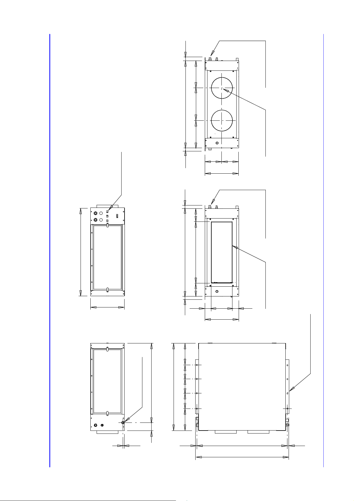
F i g . 4 --- E v a p o r a t i n g u n i t HPSE 06 (version with freecooling)
310
unit fixing
N. 8 slots 9x12---
70994
RIGHT SIDE VIEW
Condensate drain
14.5
150 150 125
803
228 150
13,583313,5
860
TOP VIEW
Liebert HPS---PD---272965---20.11.2009
Page 26
28.528.5 903
Refrigerant
connection
8--2
903
375
Electrical
connection
LEFT SIDE VIEW
276,5 350 276,5
FRONT VIEW (CIRCULAR DUCTS VERSION)
187,5
187,5
375
903 28,528,5
FRONTVIEW(RECTANGULARDUCTVERSION)
150,7 601,6 150,7
N. 2 collars
ø250 H=35 mm
Refrigerant
connection
Collar
250x600 H=35 mm
61,7 251,6 61,7
Dimensional D rawings
F i g . 5 --- E v a p o r a t i n g u n i t HPSE 08 --10--12--14 (version with freecooling)
375
226,5
81588
RIGHT SIDE VIEW
Condensate drain
14.5
903
150 150
226,5 150
13,593313,5
960
unit fixing
N. 8 slots 9x12---
TOP VIEW
Liebert HPS---PD---272965---20.11.2009
Page 27
Electrical
8--3
connection
803
310
LEFT SIDE VIEW
Refrigerant
connection
803
BOTTOM VIEW
860
Dimensional D rawings
FRONT VIEW
310
28,5 803 28,5
unit fixing
N. 8 slots 9x12---
70994
RIGHT SIDE VIEW
Condensate drain
14.5
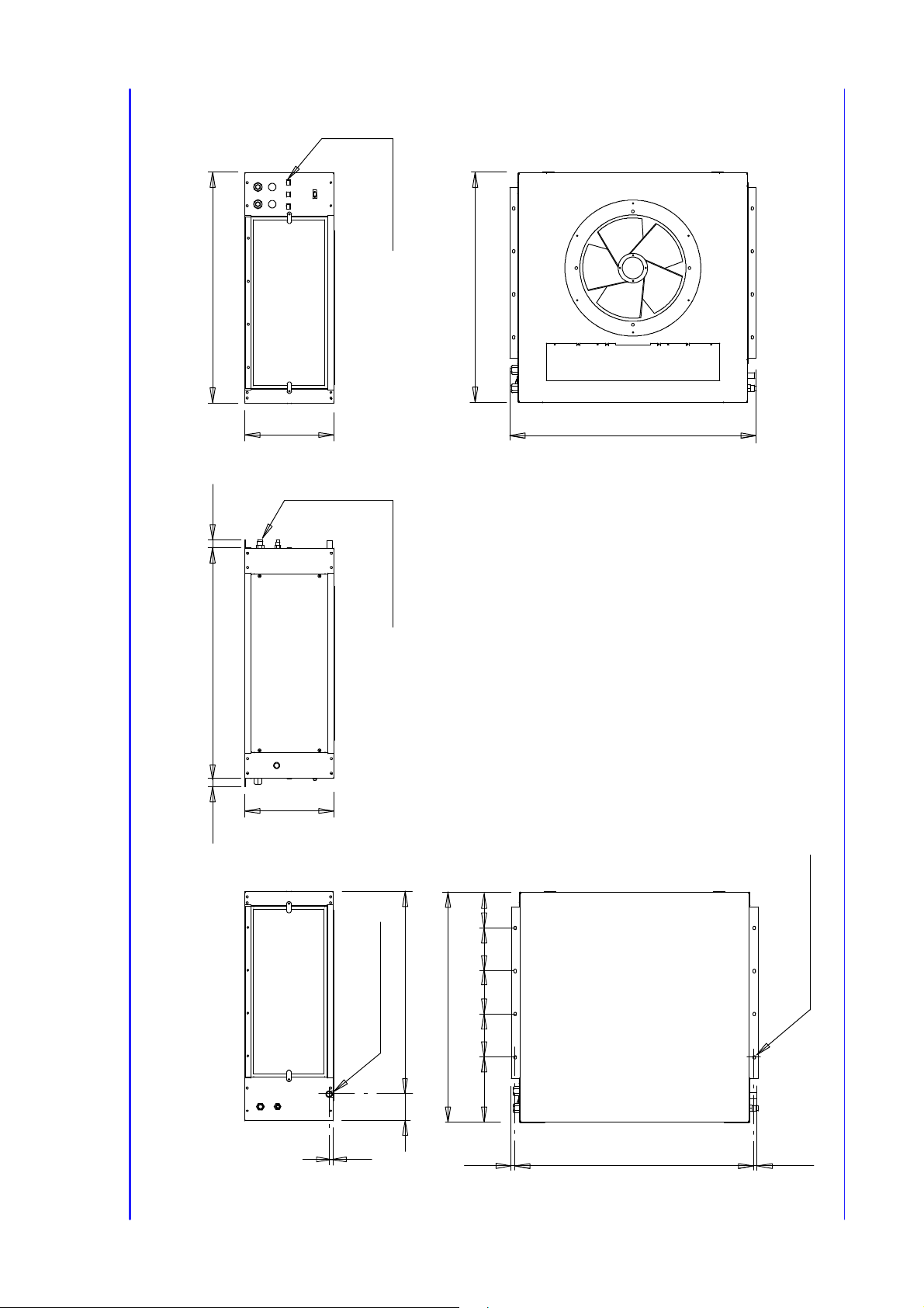
F i g . 6 --- E v a p o r a t i n g u n i t HPSE 06 --08--10 (version without freecooling)
803
228 150 150 150 125
TOP VIEW
13,583313,5
Liebert HPS---PD---272965---20.11.2009
Page 28

Electrical
8--4
connection
903
375
LEFT SIDE VIEW
Refrigerant
connection
903
BOTTOM VIEW
960
Dimensional D rawings
FRONT VIEW
375
28,5 903 28,5
unit fixing
N. 8 slots 9x12---
80994
RIGHT SIDE VIEW
Condensate drain
14.5
F i g . 7 --- E v a p o r a t i n g u n i t HPSE 12 --14 (version without freecooling)
903
226.5 150 150 150 226.5
TOP VIEW
13,593313,5
Liebert HPS---PD---272965---20.11.2009
Page 29

Dimensional D rawings
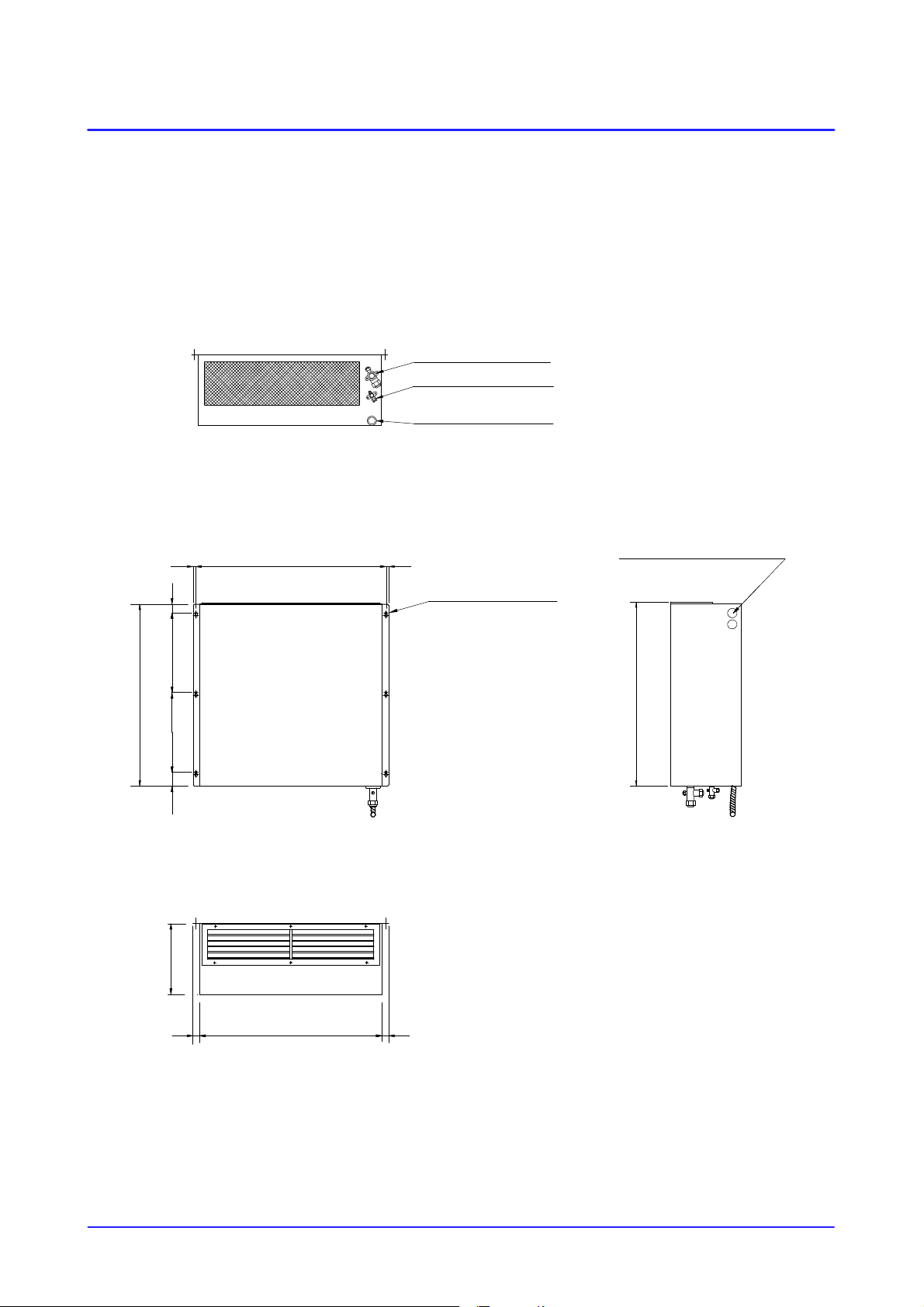
Fig. 8 --- Evaporating unit SE 06W (version with freecooling)
310
Circular ducts version
Rectangular duct version
N.2 COLLARS 4 200 HEIGHT 35 mm COLLAR 190 X 560 HEIGHT 35 mm
310
185 125
300 280220 560 15090
BOTTOM VIEW BOTTOM VIEW
90 190 30
Condensate drain Condensate drain
Refrigerant inlet
Refrigerant outlet
83412 12
Electrical connections
N.6 HOL ES 4 8
Refrigerant inlet
Refrigerant outlet
250 800
35060 350 40
REAR VIEW SIDE VIEW
310
800 2929
TOP VIEW
1050
Liebert HPS---PD---272965---20.11.2009
8--5
Page 30
Dimensional D rawings
Fig. 9 --- Evaporating unit SE 06W (version without freecooling)
Refrigerant outlet
Refrigerant inlet
Condensate drain
BOTTOM VIEW
800
35060 350 40
310
83412 12
Electrical connections
N.6 HOL ES ø8
800
REAR VIEW SIDE VIEW
80029 29
TOP VIEW
Liebert HPS---PD---272965---20.11.2009
8--6
Page 31

Dimensional D rawings
Fig. 10 --- Evaporating unit SE 08--10 --13 -- 14W (version with freecooling)
Circular ducts version Rectangular duct version
395
220 175220 175
50
N.2 COLLARS 4 250 HEIGHT 35 mm
310 350 395
BOTTOM VIEW
Refrigerant inlet Refrigerant inlet
Refrigerant outlet Refrigerant outlet
395
250
95 50
N.8 HOL ES 4 8
COLLAR 250 X 600 HEIGHT 35 mm
185 600 270
BOTTOM VIEW
Condensate drainCondensate drain
Electrical connections
32090 320320
1100
295
REAR VIEW SIDE VIEW
395
30 1055 30
TOP VIEW
1395
Liebert HPS---PD---272965---20.11.2009
8--7
Page 32

Dimensional D rawings
Fig. 11 --- Evaporating unit SE 08--10 --13 -- 14W (version without freecooling)
Refrigerant outlet
Refrigerant inlet
400
Condensate drain
BOTTOM VIEW
1100
320 50320
320
400
1086 1717
Electrical connections
N.8 HOL ES 4 8
1100
90
REAR VIEW
SIDE VIEW
TOP VIEW
Liebert HPS---PD---272965---20.11.2009
1052
3434
8--8
Page 33

A
8--9
338
FRONT VIEW
132 656 132
A
80535
outlet
Refrigerant
inlet
Refrigerant
1818
Electrical
connections
390
SIDE VIEW
354
390
A --- A S e c .
Dimensional D rawings
Fig. 12 --- Condensing unit HPSC 06-- 08
outlet
Refrigerant
840
920
REAR VIEW
inlet
Refrigerant
Liebert HPS---PD---272965---20.11.2009
Page 34

A
8--10
27
656
FRONT VIEW
27
132 132
A --- A S e c .
338
A
115535
outlet
Refrigerant
1190
inlet
Refrigerant
Electrical
connections
390
SIDE VIEW
354 1818
390
Dimensional D rawings
Fig. 13 --- Condensing unit HPSC 10--12 --14
outlet
Refrigerant
920
REAR VIEW
inlet
Refrigerant
Liebert HPS---PD---272965---20.11.2009
Page 35

9
F i g . 1 4 --- HPSE 06 --08 --10 --12--14 evaporating unit ceiling installation (version without freecooling)
Installation
min. 300
Service area
for electical
board
803 (HPSE 06--08--10)
903 (HPSE 12--14)
min. 200
310 (HPSE 06--08--10)
375 (HPSE 12--14)
Ceiling fixing points
Liebert HPS---PD---272965---20.11.2009
9--1
Page 36

Installation
F i g . 1 5 --- HPSE 06 --08 --10 --12--14 evaporating unit installation (version with freecooling)
C
Service area
for electical
Service area
for Freecooling
min. 300
A
filter
board
B
min. 200
HPSE A B C
06 min. 300 803 310
0 8 --- 1 0 --- 1 2 --- 1 4 min. 320 903 375
3
5
1
4
2
ITEM DESCRIPTION
3
3
1 Electrical box accessibility
2 Support for filter
3Airfilter
4 Freecooling filter accessibility
Electrical box
5
Liebert HPS---PD---272965---20.11.2009
9--2
Page 37

Installation
F i g . 1 6 --- HPSE 06 --08 --10 --12--14 evaporating unit ceiling installation (version with freecooling)
4
1
10
11
9
23
8
7
6
5
5
ITEM DESCRIPTION
1 Wall p late for circular duct 13503801 13536101
2 2 flexible ducts with fixing clamps, L = 0.5 m 270190 (ø 202mm) 270191 (ø 254mm)
3 F i x i n g c l a m p s --- ---
4 Wall plate for rectangular duct 13501801 13536001
5 C i r c u l a r / r e c t a n g u l a r v e r s i o n --- ---
6 Wall hole 400 x 200mm 600 x 400mm
7 Overpressure damper 134948 134992
8 Grille for overpressure damper 270206 117832
9 Aluminium grille with metallic prefilter 270202 270219
10 Metallic prefilter (included in item 9) -- - ---
11
Liebert HPS---PD---272965---20.11.2009
Wall hole 550 x 210mm 590 x 230mm
COD.
HPSE 06
H P S E 0 8 --- 1 0 --- 1 2 --- 1 4
COD.
9--3
Page 38

Installation
F i g . 1 7 --- SE 06 -- 08 --10--13--14W service area
A
CB D
B
E
C
VERSION WITH FREECOOLING
VERSION WITHOUT FREECOOLING
F i g . 1 8 --- SE 06 -- 08 --10--13--14W evaporating unit wall installation
With freecooling option
AIR CONDITIONED
BC DA
200 300 300 0
200 100 0 0
Without freecooling option
AIR CONDITIONED
E
700
700
OUTSIDE AIR
Liebert HPS---PD---272965---20.11.2009
1050 (SE 06W)
min. 500
1395 (SE 08--- 10 --- 13 ---14W)
1550 (SE 06W)
1895 (SE 08--- 10 --- 13 ---14W)
AIR RETURN
800 (SE 06W)
1000 (SE 06W)
1100 (SE 08--- 10 --- 13 ---14W)
1300 (SE 08--- 10 --- 13 ---14W)
min. 200
AIR RETURN
9--4
Page 39

Installation
F i g . 1 9 --- SE 06 -- 08 --10--13--14W evaporating unit wall installation (version with freecooling)
3
2
1
6
7
5
4
10
11
8
8
9
9
ITEM DESCRIPTION
1 SE_W with FC option (optional rectangular hole) --- ---
2 S E _ W w i t h F C o p t i o n (s t a n d a r d c i r c u l a r h o l e ) --- ---
3 Overpressure damper 134948 134992
4 Grille for overpressure damper 270206 117832
5Holeinthewall 400 x 200 mm 600 x 400 mm
6 2 FC flexible ducts L=0.5 m, with fixing clamps 270190 (∅ 202) 270191 (∅ 254)
7 Wall plate for FC circular duct 13503801 13536101
8 Aluminium grille with metallic prefilter 270202 270219
9 Metallic prefilter (included in (8) -- - ---
10 Hole in the wall 550 x 210 mm 590 x 230 mm
11
Wall plate for FC rectangular duct 13501801 13536001
10
SE
06W
CODE
SE
0 8 --- 1 0 --- 1 3 --- 1 4 W
Liebert HPS---PD---272965---20.11.2009
9--5
Page 40

Installation
F i g . 2 0 --- HPSC 06 -- 08 -- 10 --12--14 condensing unit installation components
1
2
3
4
5
3
2
1
HPSC 06--- 08
H P S C 1 0 --- 1 2 --- 1 4
ITEM DESCRIPTION
1 Nut
2 Serrated lock washer
3Washer
4 Anti--- vibrating mount
Bracket
5
Liebert HPS---PD---272965---20.11.2009
9--6
Page 41

Installation
F i g . 2 1 --- HPSC 06 -- 08 -- 10 --12--14 service and working area
3
1
WALL IN FRONT
OF UNITS
WALL BEHIND
UNITS
2
4
WALL IN FRONT
OF UNITS
WALL BEHIND
UNITS
If H1 < 0.5 x H2 ⇒ L min. = 500 mm.........
If 0.5 x H2 ≤ H1 ≤ H2 ⇒ L min. = 800 mm...
5
If H1 > H2 ⇒ Not allowable configuration..............
Liebert HPS---PD---272965---20.11.2009
5
M U LT I --- R O W S
INSTALLATION
9--7
Page 42

Installation
F i g . 2 2 --- Liebert HPS (HPSE + HPSCxx0/A) suggested refrigerant connections
Gas pipeline
(Sloping 1%)
(External Unit)
3mmax.
vertical distance
(External Unit)
HPSC
HPSC
Liquid/gas pipeline
10 m max. horizontal equivalent length
Gas pipeline
(Sloping 1%)
Gas pipeline
(Sloping 1%)
Liquid/gas pipeline
7 m max. horizontal equivalent length
HPSE
(Internal Unit)
Syphons (obligatory)
HPSE
(Internal Unit)
HPSC
(External Unit)
Liebert HPS---PD---272965---20.11.2009
Gas pipeline
(Sloping 1%)
Liquid/gas pipeline
Gas pipeline
(Sloping 1%)
HPSE
(Internal Unit)
B
two syphons
5mmax.vertical
distance between
NOTE:
A
Max. equivalent length for
refrigerant line A + B =10m
9--8
Page 43

Installation
F i g . 2 3 --- Liebert HPS (HPSE + HPSCxxL, Long piping) suggested refrigerant connections
Gas pipeline
(Sloping 1%)
HPSC
(External Unit)
HPSC
(External Unit)
20 m max.
vertical distance
Liquid/gas pipeline
50 m max. horizontal equivalent length
Gas pipeline
(Sloping 1%)
two syphons
5mmax.vertical
distance between
Liquid/gas pipeline
30 m max. horizontal equivalent length
Syphons (obligatory)
Gas pipeline
(Sloping 1%)
HPSE
(Internal Unit)
HPSE
(Internal Unit)
HPSC
(External Unit)
Liebert HPS---PD---272965---20.11.2009
Gas pipeline
(Sloping 1%)
Gas pipeline
(Sloping 1%)
Liquid/gas pipeline
30 m max. horizontal equivalent length
HPSE
(Internal Unit)
two syphons
5mmax.vertical
distance between
20 m max. vertical distance
9--9
Page 44

Installation
F i g . 2 4 --- Liebert HPSW (SE_W + HPSCxxA) suggested refrigerant connections
HPSC
(External Unit)
Gas pipeline
(Sloping 1%)
Liquid/gas pipeline
10 m max. horizontal equivalent length
Syphons
(obligatory)
SE_W
(Internal Unit)
SE_W
Gas pipeline
(Sloping 1%)
Gas pipeline
(Sloping 1%)
3mmax.
vertical distance
HPSC
(External Unit)
Liquid/gas pipeline
7 m max. horizontal equivalent length
(Internal Unit)
SE_W
(Internal Unit)
HPSC
(External Unit)
Gas pipeline
(Sloping 1%)
Liebert HPS---PD---272965---20.11.2009
Gas pipeline
(Sloping 1%)
Liquid/gas pipeline
B
vertical
distance
between
5mmax.
two syphons
A
NOTE:
Max. equivalent length for
refrigerant line A + B =10m
9--10
Page 45

Installation
F i g . 2 5 --- Liebert HPSW (SE_W + HPSCxxL, Long piping) suggested refrigerant connections
HPSC
(External Unit)
(Internal Unit)
Gas pipeline
(Sloping 1%)
Liquid/gas pipeline
50 m max. horizontal equivalent length
Syphons
(obligatory)
Gas pipeline
(Sloping 1%)
SE_W
(External Unit)
20 m max.
vertical distance
HPSC
HPSC
(External Unit)
Gas pipeline
(Sloping 1%)
between
5mmax.
two sypho ns
vertical distance
Liquid/gas pipeline
30 m max. horizontal equivalent length
Gas pipeline
(Sloping 1%)
SE_W
(Internal Unit)
SE_W
(Internal Unit)
Liebert HPS---PD---272965---20.11.2009
Gas pipeline
(Sloping 1%)
Liquid/gas pipeline
30 m max. horizontal equivalent length
20 m max.
vertical distance
vertical
distance
between
5mmax.
two syphons
9--11
Page 46

Page 47

Il Fabbricante dichiara che questo prodotto è conforme alle direttive Europee:
The Manufacturer hereby declares that this product conforms to the European Union directives:
Der Hersteller erklärt hiermit, dass dieses Produkt den Anforderungen der Europäischen Richtlinien gerecht wird:
Le Fabricant déclare que ce produit est conforme aux directives Européennes:
El Fabricante declara que este producto es conforme a las directivas Europeas:
O Fabricante declara que este produto está em conformidade com as directivas Europeias:
Tillverkare försäkrar härmed att denna produkt överensstämmer med Europeiska Uniones direktiv:
De Fabrikant verklaart dat dit produkt conform de Europese richtlijnen is:
Since the Liebert HIROSS Company has a policy of continuous
product improvement, it reserves the right to change design and
specifications without previous notice.
Vaimistaja vakuuttaa täten, että tämä tuote täyättää seuraavien EU---direktiivien vaatimukset:
Produsent erklærer herved at dette produktet er i samsvar med EU---direktiver:
Fabrikant erklærer herved, at dette produkt opfylder kravene i EU direktiverne:
Ο Κατασευαστ δhλνει τι τo παν πoΪν εναι ατασευασνo αφwνα ε τι oδhγε τh Ε.Ε.:
2006/42/EC; 2004/108/EC; 2006/95/EC; 97/23/EC
Printed in Italy by Liebert HIROSS S.p A.
Issued by T.D.Service
Page 48

Ensuring The High Availability
Of Mission-Critical Data And Applications.
Emerson Network Power, a business of Emerson (NYSE:EMR), is
the global leader in enabling Business-Critical Continuity™ from
grid to chip for telecommunication networks, data centers, health
care and industrial facilities. Emerson Network Power provides
innovative solutions and expertise in areas including AC and DC
power and precision cooling systems, embedded computing and
power, integrated racks and enclosures, power switching and
controls, monitoring, and connectivity. All solutions are supported
globally by local Emerson Network Power service technicians.
Liebert power, precision cooling and monitoring products and
services from Emerson Network Power improve the utilization
and management of data center and network technologies by
increasing IT system availability, fl exibility and effi ciency. For more
information, visit www.liebert.com, www.emersonnetworkpower.
com or www.eu.emersonnetworkpower.com
While every precaution has been taken to ensure the accuracy
and completeness of this literature, Liebert Corporation assumes no
responsibility and accepts no liability for damages resulting from use of
this information or for any errors or omissions.
©2008 Liebert Corporation
All rights reserved throughout the world. Specifi cations subject to change
without notice.
Liebert and the Liebert logo are registered trademarks of Liebert
Corporation. All names referred to are trademarks
or registered trademarks of their respective owners.
Locations
Emerson Network Power - Headquarters EMEA
Via Leonardo Da Vinci 16/18
Zona Industriale Tognana
35028 Piove di Sacco (PD) Italy
Tel: +39 049 9719 111
Fax: +39 049 5841 257
marketing.emea@emersonnetworkpower.com
Emerson Network Power - Service EMEA
Via Leonardo Da Vinci 16/18
Zona Industriale Tognana
35028 Piove di Sacco (PD) Italy
Tel: +39 049 9719 111
Fax: +39 049 9719045
service.emea@emersonnetworkpower.com
United States
1050 Dearborn Drive
P.O. Box 29186
Columbus, OH 43229
Tel: +1 614 8880246
Asia
7/F, Dah Sing Financial Centre
108 Gloucester Road,Wanchai
Hong Kong
Tel: +852 2572220
Fax: +852 28029250
Emerson Network Power
The global leader in Business-Critical Continuity™.
AC Power
Connectivity
DC Power
Emerson Network Power and the Emerson Network Power logo are trademarks and service marks of EmersonElectric Co. ©2008 Emerson Electric Co.
Embedded Computing
Embedded P
ower
Monitoring
Outside Plant
P
ower Switching & Control
Precision Cooling
Rack & Integrated Cabinets
Se
rvices
Surge Protection
 Loading...