

Page 1

Liebert HPC--S
006--022
Air Cooled Chillers with Scroll compressor/s
Precision Cooling for
Business--Critical Continuity
Liebert HPC--S 006--022 -- PD -- 273571 -- 01.03.2012
PRODUCT DOCUMENTATION
Page 2

Liebert HPC-- S 006-- 022
L ie b e rt HP C --- S 00 6 --- 0 22
Liebert HPC-S 006---022 is the new Emerson Network Power product line of air-cooled water
chillers, from 60 to 220 kW, designed to combine the best performance in terms of efficiency and
reliability with the lowest impact on the environment and to offer a flexible solution for each different
application requirement of this product.
Utilising hermetic Scroll compressors, heat exchangers and fans of the latest generation,
specifically designed for air conditioning applications, the new series stands out for its unrivalled
efficiency, outstanding compactness and low sound emissions.
The “Freecooling” execution and “Supersaver Evolution” system, providing complete integration
with indoor air conditioning units, allow the achievement of extraordinary energy savings and
increase system lifetime and reliability.
With @connectivity, a highly sophisticated way to let the system components communicate,
Liebert HPC-S 006---022 is part of the network created for an improved operations management
system and significant energy saving.
L i e b e r t H P C --- S 0 0 6 --- 0 2 2
Solutions Committed to your Business
Liebert HPC--- S 006---022 --- PD- -- 273571--- 01.03.2012
Page 3

Lie b ert HP C --- S 00 6 --- 022
Contents
Liebert HPC-- S 006-- 022
1
Features and Benefits
2
Model Number Description
3
Operating Range
4
Technical Data
5
Mechanical Specifications
6
Controls
Performance Adjustment
7
Factors
The Quality Management
System of Emerson Network
Power S.r.l. High Performance
Air Conditioning has been
approved by Lloyd's Register
Quality Assurance to the
quality management system
standard ISO 9001:2008
The product conforms to European Union directives
2006/42/EC; 2004/108/EC; 2006/95/EC and
97/23/EC.
Units are supplied complete with a test certificate
and conformity declaration and control component
list.
8
9
10
11
12
13
Sound Levels
Electrical Data
Application Considerations
Dimensional Data
Refrigerant Circuit
Hydraulic Circuit
Liebert HPC-- S 006 -- 022 units are CE marked as
they comply with the European directives
concerning mechanical, electrical, electromagnetic
and pressure equipment safety.
Liebert HPC--- S 006---022--- PD--- 273571---01.03.2012
Page 4

1
Features and Ben efits
Features and Benefits
Reliability and Low Environmental Impact
Reliability
The L i e b e r t H P C --- S 0 0 6 --- 0 2 2 series is equipped with two hermetic scroll compressors, which represent state ---of ---the ---art technology in this sector. They
have been designed and optimized for air---cooledwater chillers within air conditioning applications.
The high volumetric efficiency ensures excellent performances of the Liebert
H P C --- S 0 0 6 --- 0 2 2 units at full load operation and especially at partial load.
Extremely low noise operation and the absence of vibrations aid the installation
of the unit in city sites requiring strict noise limits.
The wide operating range, bearing lubrication, component oversizing, absence
of vibrations and few moving parts, together with the resistance to liquid slugging and compressor electronic control integrated with the machine microprocessor enhancethe well---known characteristics of operating reliability and long
life typical of this compressors type.
AllL i e b e r t H P C --- S 0 0 6 --- 0 2 2 units are run testedat the factory before shipment.
High outdoor temperature
The oversizing of heat exchangers and the wide operating range of the scroll compressors permit the
use of L i e b e r t H P C --- S 0 0 6 --- 0 2 2 units in high temperature environments as well, up to 46° C at 100%
full load.
Resistance to liquid slugging
The robust design of the scroll compressors can tolerate/withstand amounts of liquid refrigerant that
would severely damage reciprocating compressor valves, piston rods and cylinders.
Low Sound Emission
The L i e b e r t H P C --- S 0 0 6 --- 0 2 2 series is characterized by unrivalled low sound emissions.
Compressors supported on anti--- vibration mounts and positioned in a closed compartment, common
to all versions; fans specifically designed to reduce the sound emissions, a special compressor jacket
on the “B” version “models from C/FB0 011” (Digit 11 = B or D) and “G” version with 900 mm fans, and
also aspecial compressor’sbox insulated on the “G” version with 800 mm fans “models from C/FG0 011”
allow the achievement of such performance.
All the models are equipped with stepless fan speed control, thanks to a special algorithm on the iCOM
board, the fan speed could be kept to the minimum. It is possible to reach even lower sound emissions
with EC fans (electronically commutated fans), which especially during reduced speed operation, allow
noise levels around 50% lower than the values measured at the same conditions with traditional fans.
L i e b e r t H P C --- S 0 0 6 --- 0 2 2 series sound emissions at 1 m distance
82
77
72
dB(A)
67
62
57
006
G --- v e r s i on
B --- v e r s i o n
B --- v e r s i o n + 8 0 0 + C J
G --- v e r s i on + 8 0 0 + C J + B o x
Liebert HPC--- S 006---022--- PD- -- 273571---01.03.2012
007 009 011 014 015 018 019 022
Models
800 = 800 mm fans diameter;
CJ = Compressor noise insulation Jacket;
Box = Box noise insulation.
1--1
Page 5

Features and Benefits
In the ”G” version chiller , the characteristics of the ”EC” fans can achieve significant noise reductions
according their speed (RPM), as shown in the chart below.
100
98
96
94
92
dB(A)
90
88
86
84
FG0 014 chiller (with CJ) PWL noise emission
500 550 600 650 700 750 800 850 900 950 1000
EC fans RPM
Unequalled Efficiency and Energy Saving
The use of hermetic Scrollcompressors of the latest generation;plate heat exchanger evaporatorsselected for R410A application; aerodynamic profiled blade fans with high efficiency nozzles; large surface
condenser coils ensure the achievement of unequalled efficiency figures.
Freecooling Module
The “Freecooling”execution allows L i e b e r t H P C --- S 0 0 6 --- 0 2 2 to take advantage of low outdoor air temperatures in the water cooling process in order to save energy, by avoiding compressors running.
A three--- way valve arrangement permits the coolant to be diverted via the additional heat exchangers
before being fed into the cooling evaporator.
This means that even if the outsideambient temperature is not low enoughto provide the completecooling load, asignificant contribution to the running costsof the system can be made whenever theambient
temperatures falls below the coolant inlet temperature.
Reduced space requirements in comparison with a conventional chiller plus a dry ---cooler, are obtained
through the “Freecooling” execution’s compact design and the reduction of the compressors working
hours offers exceptional saving both in the long and short term.
The different strategies adopted by the proprietary microprocessor control in managing the various components, fans --- compressors --- regulation valves, and operating modes, mechanical and/or free cooling, together with the compressors’ partialisation ensure typical energy savings greater than 30%.
VENICE HAMBURG
8,000
7,000
6,000
5,000
4,000
3,000
2,000
1,000
0
Annual Power consumption (kWh)
-6-4-202468101214161820222426283032
Outdoor temperature (
o
C)
8,000
7,000
6,000
5,000
4,000
3,000
2,000
1,000
0
-18-16-14-12-10-8-6-4-202468101214161820222426283032
Annual Emergency consumption (kWh)
Outdoor temperature (
o
C)
Annual energy consumption, Chiller.
Annual energy consumption, Chiller plus Freecooling module.
Liebert HPC--- S 006---022--- PD--- 273571---01.03.2012
1--2
Page 6

Features and Benefits
Seasonal Efficiency
The ”Freecooling” execution finds its best application in combination with the “Supersaver Evolution”
system which regulates the coolant temperatures according to the variation of the thermal load, increasing the numbers of hours during which free cooling is possible.
The percentage of energy saving can thus be greater than 35%.
Annual power consumption. Comparison among the systems:
12
Chiller
Superchiller
10
Superchiller + Supersaver
8
6
4
Energy consumption (MWh)
2
0
Jan Feb Mar Apr May Jun Jul Aug Sep Oct Nov Dec
T r aditional Chiller
Freecooling execution
--- Supersaver Evolution
Integration with Indoor Air Conditioners
Supersaver Evolution System
A special working mode can be set up in combination with Emerson Network Power HPAC indoor units
to obtain the ”Supersaver Evolution” system, that enhances the energy saving capabilities and thus optimizes the SEER (Seasonal Energy Efficiency Ratio) of the system.
Through @connectivity the information on the cooling needs of the air conditioners is available to the
L i e b e r t H P C --- S 0 0 6 --- 0 2 2 units, that will manage their resources (compressorsand free cooling) in the
most efficientway in order to save additional energy.
This solution does not require any
modification, mechanical or
electrical thus avoiding additional components
and regulation algorithms which
could undermine the
reliability of the system.
@ Connectivity
When the room units
are equipped with
thesametypeofcontrol system Emerson
Network Power
(iCOM and CDL), it is
possible to maximize
the energy savings and improve the total operation management.
Liebert HPC--- S 006---022--- PD--- 273571---01.03.2012
1--3
Page 7
Features and Benefits
The solution is @connectivity, which is a highly sophisticated way to let the system components (the
Air--- Conditioners as well as the L i e b e r t H P C --- S 0 0 6 --- 0 2 2 units, Chiller and Freecooling executions)
talk to each other.
The @connectivity plug--- in allows the setting of different working modes for different situations, such
as:
D higher water temperature in low load operation (energy saving);
D lower water temperature for dehumidification (better performance);
D special ”night” Setpoint (energy saving & noise reduction);
D lower water temperature if one or more Air Conditioners fail (keep capacity in emergency situations);
D ...andmuchmore!
To add th e @connectivity to your system, it is simply necessary:
To build up Hironet connection between the room units and the L i e b e r t H P C --- S 0 0 6 --- 0 2 2 units. The
network can be only 1 (if the distance and the number of units allow this) or it can be split in several networks.
On @connectivity it is possible to define the rules that you want your system to respect.
It will be then up to the web capabilities to allow the view and control of your system from any PC of your
Local area network (provided that the @connectivity PC is connected on the LAN) or even if you have
a connection to Internet and your system is open to external access, you will have the possibility to view
and control your system via Internet
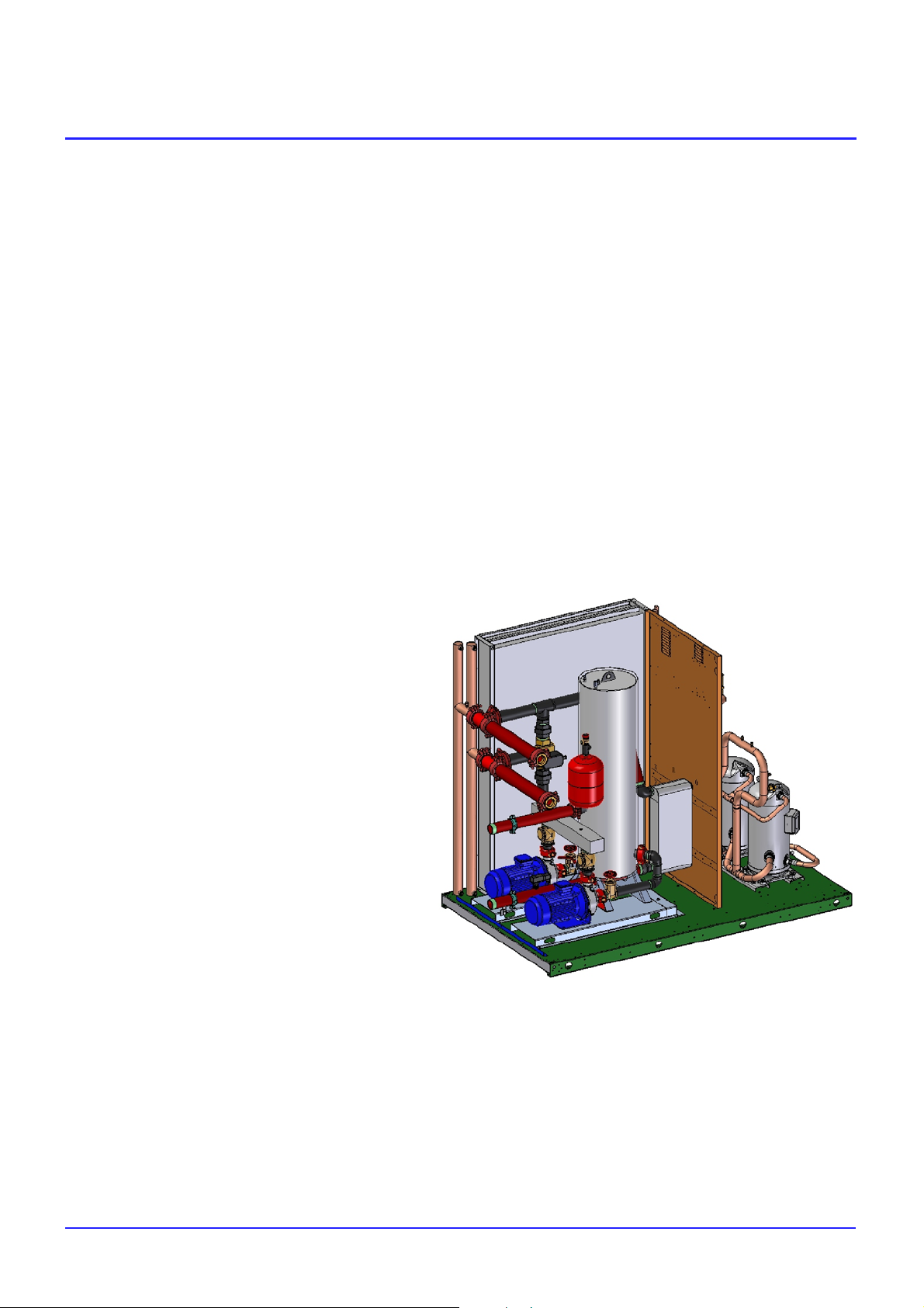
Flexibility: Hydronic Module
In orderto match different kinds of installations andapplications, Liebert HPC -S 006--- 022 units
are available with a hydronic module, which can be adapted/adjusted depending on thespecific requests.
Based on this philosophy, the
units can be equipped with
everything that is needed for
the correct installation and, in
this way, reduce the complexity
of the commissioning: buffer
tank, 1 or 2 circulating pumps,
water filter, safety valve, expansion vessel, flow switch. With all
these elements included inside
the unit, it is just a matter of connecting the chiller to the system.
But, if some or all of these components are already presentin the hydraulic line, Liebert HPC-S 006-022 can
be equipped only with what is not already connected in the system. This level of flexibility allows true customisation of the unit.
Compactness: Small Footprint
The L i e b e r t H P C --- S 0 0 6 --- 0 2 2 series achieves the high efficiency performance and low soundemission
previously described with a compactness which is one the highest in its category.
This result ispossible thanks to the high quality componentsselected and a design whichtakes into consideration the different aspects and needs of a chiller installation.
In this way the installation area can be optimized, leaving more space for other building elements. Combining this aspect with the possibility of including all of the hydronic components inside the unit, Liebert
H P C --- S 0 0 6 --- 0 2 2 series is really a leader in terms of easy and compact installation
Liebert HPC--- S 006---022--- PD--- 273571---01.03.2012
1--4
Page 8

2
Model Number Description
ModelNumber Description
Model Nomenclature / Digit Numbers
1 2 3 4 5 6
G 0 0 1C 1
Specification
C = Air cooled
Chiller
F = Freecooling
Chiller
L i e b e r t H P C --- S 0 0 6 --- 0 2 2
Digits 1, 2, 3, 4, 5, 6 --- Base unit
Base unit main features
D R410A refrigerant;
D One refrigeration circuit;
D HP and LP gauges;
D Fans speed control (TRIAC or EC according B or G
version); on B versions, different options with EC fans
are available;
D On digit 11 base version B,opt.B&D+G version
opt. C compressors jacket if necessary;
D On digit 11 G version opt. D compressors jacket +
compressor’s box insulated if necessary;
D Expansion valve: TXV (Thermostatic expansion
Valv e) on B version;
EEV (Electronic Expansion Valve)
on G version;
D Flow switch and Hydraulic Kit (Hydraulic Kit =
expansion vessel and safety valve);
D Evaporator electric heater + tank electric heater will
protect piping too (only if pump/s are fitted on unit);
D Electrical panel ventilation;
D Buffer tank of 100, 200 and 300 litres (1, 2 and 3 fans).
Digit 7 --- Display and Switch
A =FTE display
B =FTE display + Network Switch
E = iCOM Coldfire display large
F = iCOM Coldfire display large + Network Switch
D i g i t 8 --- S o f t s t a r t e r
0 =None
1 = With compressors soft starter
Digit 9 --- Monitoring
0 =None
1 =ISHousing(noISCardincluded)
2 =Webcard
3 = Modbus card
4 =Sitescancard
5 = Web card + Modbus card
6 = Web card + Sitescan card
7 = Modbus card + Sitescan card
8 = Bacnet card (Bacnet or Modbus over IP)
7 8 9 10 11 12 13 14 15 16 17 18
Cooling Capacity
Cooling capacity (x 10 = kW)
Refrigerant
0 = R410A
Versions
B = Base version
G = High efficiency class version
D i g i t 1 0 --- B u f f e r t a n k
0 =None
1 = With buffer tank
2 = With buffer tank + electric heaters (only for chiller
models)
Digit 11 --- Fans options
A = TRIAC control and 900 mm fans
B =TRIAC control and 800 mm fans
C = E C --- F a n s, 9 0 0 m m
D = E C --- F a n s , 8 0 0 m m
D i g i t 1 2 --- P u m p s g r o u p (expansion tank and water
safety valve always included as standard)
1 =Nopumps
2 = With 1 pump LP (low pressure)
3 = With 1 pump HP (high pressure)
4 = With 2 pumps LP (low pressure)
5 = With 2 pumps HP (high pressure)
D i g i t 1 3 --- F r e e
Digit 14 --- Electric panel options
0 =None
1 = With electric heaters
A = Fast start ramp
B =Fast start ramp and electric heaters
Digit 15 --- Evaporator antifreeze protection
0 =None
1 = With evaporator antifreeze protection
2 = With evaporator and pipe antifreeze protection
Digit 16 --- Compressor power factor correction
0 =None
1 = With compressors power factor capacitors
Digit 17 --- Coil metal filter / Protection grid
0 =None
1 = With coil metal filter
Digit 18 --- Special requests
0 =None
X =As specified
Liebert HPC--- S 006---022 --- PD- -- 273571--- 01.03.2012
2--1
Page 9

Model Number Description
Kits / Accessories shipped loose
D Anti-vibrating mounts (spring or rubber)
D Dee shackle UNI 1947
D Coldfire IP40 remote box
D Water filter
Configuration Rules
In order to give the units the highest flexibility and a high option number, it is necessary to follow
the configuration rules indicated here below, so as to select the unit with all compatible options:
Rule valid for all Chiller and Freecooling versions:
Compressor soft starter are not electrically compatible with compressors power factor corrections
D if digit 8 = 1 than digit 16 = 0
on digit 11: A & B not available on G version (default: A with Base version and C with G ver-
sion)
Rules valid for Chiller versions only (on Freecooling chillers electric heaters are
not available):
Heating resistors have to be selected according to the presence of the pumps, tank, etc.
D if digit 15 = 1 or 2, then digit 10 = 0 or 2
D if digit 15 = 1, then digit 12 = 2, 3, 4 or 5
D if digit 15 = 2, then digit 12 = 1
D ifdigit10=2,thendigit15=1or2
Liebert HPC--- S 006---022 --- PD- -- 273571--- 01.03.2012
2--2
Page 10
3
Operatin gRan ge
Operating Range
Working Limits
Minimum temperature of outdoor air entering condenser coils (with standard operating unit):
-- -25 ° C for Freecooling models;
---10°CforChillermodels.
Maximum outdoor air temperature is in relation to each model, as indicated in the following tables.
High water flow values (corresponding to a thermal difference at the evaporatorlower than3.5° C --- 4° C)
may cause corrosions and vibrations inside the plate heat exchanger and in the hydraulic circuit.
The Minimum water flow allowed corresponds to a maximum temperature difference of 8° C.
More extreme operating conditions would active safety devices and the unit would be stopped.
The outlet water temperature must range from 4° C to 15° C.
The maximum allowed water return temperature, when the unit isin full operation, is 20° C; return temperatures over 20° C are allowed only during start---up.
The “G” version with EC fans 900mm (digit 11 = C) admit Maximum Outlet Water Temperature of 20 ° C
and Maximum Water Return Temperatur e of 26° C when the units are at full power.
The maximum permitted glycol percentage is 50% (35% with standard pump groups fitted).
The necessary minimum glycol percentage depends on the minimum ambient air temperature conditions referred to the place of installation.
The maximum hydraulic working pressure is 6 barg (safety valve set at 6 barg, optional).
Nominal power supply tolerance: 400V
See “Operation range” table reporting the limits for each model; for different values ask your agent.
All the working limits indicated in both diagrams and tables refer to steady ---state operation mode.
Unit storage conditions:
D between ---10 ° C and + 45 ° C for all models; humidity: 80% R.H. non-condensing.
+
/
10%; max. voltage unbalance: 2%.
---
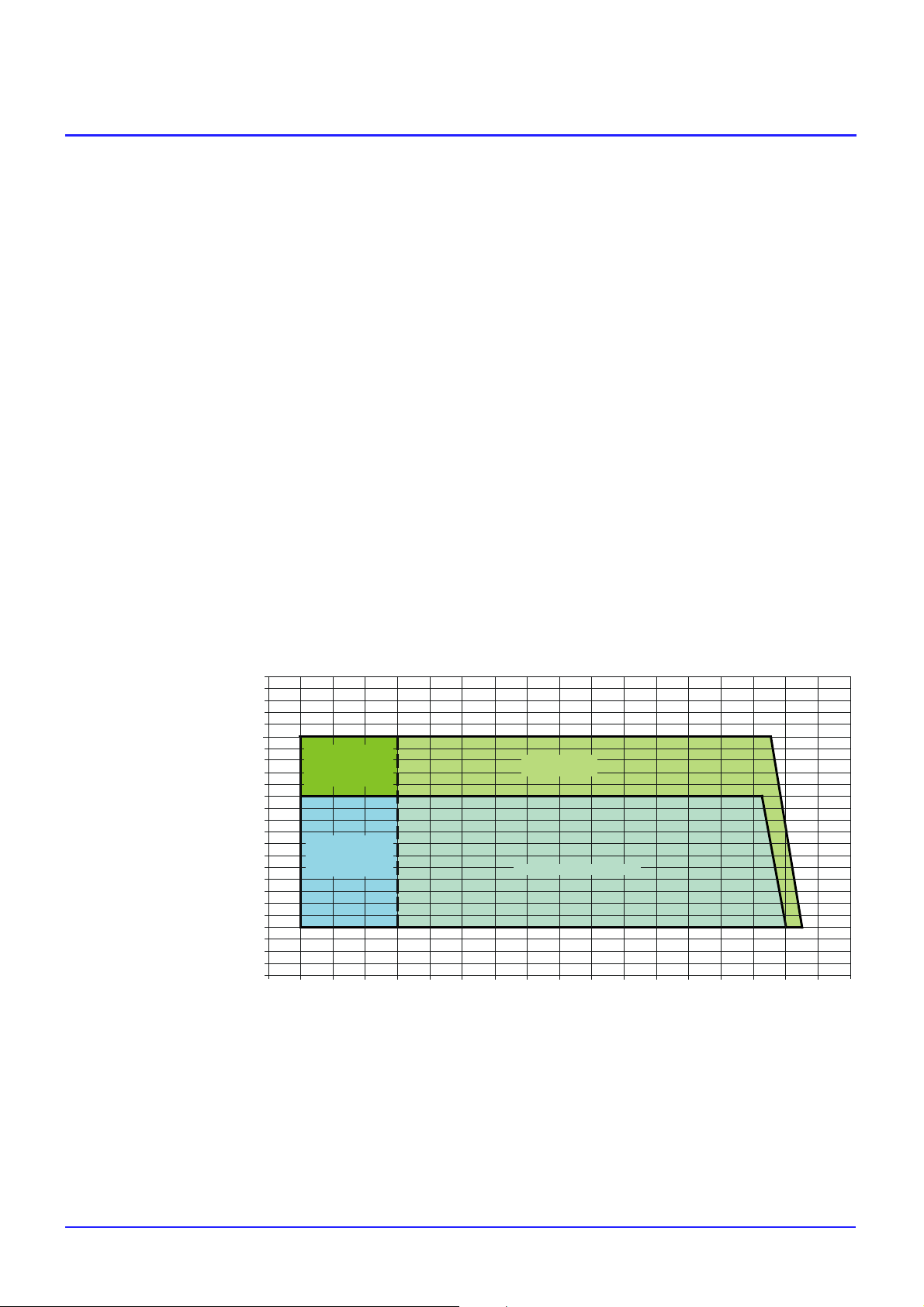
A v e r a g e H P C --- S 0 0 6 --- 0 2 2 W o r k i n g L i m i t s
25
24
23
22
21
LWT (_C)
20
19
18
17
16
15
14
13
12
11
10
9
8
7
6
5
4
3
2
1
0
Freecooling
only
Gmodels
Freecooling
only
All models
Only
Gmodels
All models
Ambient Temperature (_C)
This diagram shows the average working limits of all the products family.
Refer to table 3 for the working limits of each unit.
5550454035302520151050--- 5--- 10--- 15---2 0--- 2 5--- 3 0
60
Liebert HPC--- S 006---022--- PD--- 273571---01.03.2012
3--1
Page 11

Operating Range
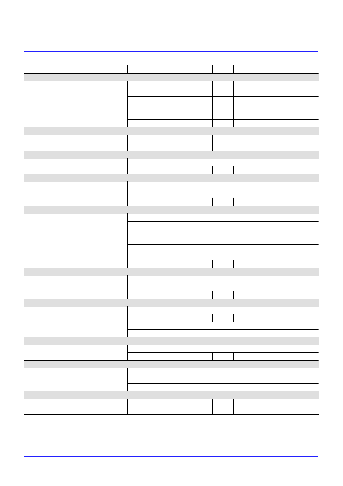
Tab. 3a --- Operating range --- Chiller with AC fans 900mm
Models: CB0 006 ---022 006 007 009 011 014 015 018 019 022
Operating range
Max. outdoor temperature
(1)
Safety devices settings
High pressure switch
(1)
High pressure safety valve
HP safety valves (each circuit)
High pressure safety valve connection
Low pressure switch
(1) --- With nominal air flow; water outlet temperature 7° C; full load; R410A refrigerant.
Tab. 3b --- Operating range --- Chiller with AC fans 800mm
Models: CB0 006 ---022 006 007 009 011 014 015 018 019 022
Operating range
Max. outdoor temperature
Safety devices settings
High pressure switch
High pressure safety valve
HP safety valves (each circuit)
High pressure safety valve connection
Low pressure switch
(1)
(1)
°
C 52.0 49.5 54.0 52.5 50.0 48.5 52.0 50.5 49.0
barg
barg
Nr.
inch
barg
°
C 50.0 47.0 52.5 50.5 48.0 46.0 50.0 48.0 46.5
barg
barg
Nr.
inch
barg
42
45
1
3/4” G
4.4
42
45
1
3/4” G
4.4
(1) --- With nominal air flow; water outlet temperature 7° C; full load; R410A refrigerant.
Tab. 3c --- Operating range --- Chiller with EC fans 900mm
Models: CG0 006 ---018 006 007 009 011 014 015 018
Operating range
Max. outdoor temperature
(1)
°
C 53.0 56.0 56.0 53.5 55.5 54.0 53.0
Safety devices settings
High pressure switch
High pressure safety valve
HP safety valves (each circuit)
High pressure safety valve connection
Low pressure switch
(1) --- With nominal air flow; water outlet temperature 7° C; full load; R410A refrigerant.
(1)
barg
barg
Nr.
inch
barg
42
45
1
3/4” G
5
Tab. 3d --- Operating range --- Chiller with EC fans 800mm
Models: CG0 006 ---018 006 007 009 011 014 015 018
Operating range
Max. outdoor temperature
(1)
Safety devices settings
High pressure switch
(1)
High pressure safety valve
HP safety valves (each circuit)
High pressure safety valve connection
Low pressure switch
°
C 47.0 52.0 51.5 48.0 50.5 48.5 47.0
barg
barg
Nr.
inch
barg
42
45
1
3/4” G
5
(1) --- With nominal air flow; water outlet temperature 7° C; full load; R410A refrigerant.
Liebert HPC--- S 006---022--- PD--- 273571---01.03.2012
3--2
Page 12

Operating Range
Tab. 3e --- Operating range --- Freecooling with AC fans 900mm
Models: FB0 006 ---022 006 007 009 011 014 015 018 019 022
Operating range
Max. outdoor temperature
(1)
Safety devices settings
High pressure switch
(1)
High pressure safety valve
HP safety valves (each circuit)
High pressure safety valve connection
Low pressure switch
(1) --- With nominal air flow; mixture outlet temperature 10° C; full load; R410A refrigerant.
Tab. 3f --- Operating range --- Freecooling with AC fans 800mm
Models: FB0 006 ---022 006 007 009 011 014 015 018 019 022
Operating range
Max. outdoor temperature
Safety devices settings
High pressure switch
High pressure safety valve
HP safety valves (each circuit)
High pressure safety valve connection
Low pressure switch
(1)
(1)
°
C 50.0 47.0 53.0 51.0 48.5 46.5 50.0 48.5 47.0
barg
barg
Nr.
inch
barg
°
C 48.5 45.5 52.0 49.5 46.5 44.0 48.5 46.5 45.0
barg
barg
Nr.
inch
barg
42
45
1
3/4” G
4.4
42
45
1
3/4” G
4.4
(1) --- With nominal air flow; mixture outlet temperature 10° C; full load; R410A refrigerant.
Tab. 3g --- Operating range --- Freecooling with EC fans 900mm
Models: FG0 006 ---018 006 007 009 011 014 015 018
Operating range
Max. outdoor temperature
(1)
°
C 51.5 55.0 55.0 52.5 54.5 53.0 52.0
Safety devices settings
High pressure switch
High pressure safety valve
HP safety valves (each circuit)
High pressure safety valve connection
Low pressure switch
(1) --- With nominal air flow; mixture outlet temperature 10° C; full load; R410A refrigerant.
(1)
barg
barg
Nr.
inch
barg
42
45
1
3/4” G
5
Tab. 3h --- Operating range --- Freecooling with EC fans 800mm
Models: FG0 006 ---018 006 007 009 011 014 015 018
Operating range
Max. outdoor temperature
(1)
Safety devices settings
High pressure switch
(1)
High pressure safety valve
HP safety valves (each circuit)
High pressure safety valve connection
Low pressure switch
°
C 45.5 51.5 50.5 46.5 49.5 47.5 45.5
barg
barg
Nr.
inch
barg
42
45
1
3/4” G
5
(1) --- With nominal air flow; mixture outlet temperature 10° C; full load; R410A refrigerant.
Liebert HPC--- S 006---022--- PD--- 273571---01.03.2012
3--3
Page 13

4
TechnicalData
Ta b . 4 a --- Te c h n i c a l D a t a --- C B 0 0 0 6 --- 0 2 2 --- A C 9 0 0
CB0 model with AC 900 mm fans - R410A 006 007 009 011 014 015 018 019 022
Performance
Cooling capacity kW 58.5 70.6 86.8 111.6 132.9 146.5 175.8 193.1 215.9
Compressors power input kW 16.1 21.5 23.2 31.1 40.4 47.9 49.9 58.3 67.1
Total power input kW 18.5 23.9 28.0 35.9 45.2 52.7 57.1 65.5 74.3
Unit EER - 3.16 2.95 3.10 3.11 2.94 2.78 3.08 2.95 2.91
Water flow m3/h 10.08 12.14 14.91 19.19 22.85 25.21 30.20 33.19 37.14
Water pressure drop kPa 47 42 37 41 42 50 48 58 49
Sound level
SPL (Sound Pressure Level)
PWL (Sound Power Level)
Refrigeration circuit
Number of refrigeration circuits No 1
Refrigerant charge (each circuit) kg 10.5 10.5 13.0 18.0 20.0 20.0 27.5 27.5 28.5
Compressors
Number of compressors No
Type - hermetic scroll
Nominal power (each compressor) HP
Fans
Number of fans No 1 2 3
Type - axial
Wheel nominal diameter mm 900
RPM 1/min 900
Nominal power input (each fan) kW 2.4
Fans power input kW 2.4 4.8 7.2
Air flow rate m3/h 21900 21400 44800 43800 42800 42800 65700 65700 64200
Evaporator
Number of evaporators No 1
Type - brazed plate heat exchanger
Internal volume (refrigerant side) l 4.1 5.1 5.6 7.6 9.2 9.2 11.6 11.6 14.8
Condensing coil
Material tubes / Fins - aluminium / aluminium
Rows / Fins space No/mm 3 / 1.8 3/1.6 2/1.8 3/1.8 3/1.6 3/1.6 3/1.8 3/1.8 3/1.6
Face area m
Internal volume (each coil) l 7.3 9.8 14.7 22.0
Water connections
Diameters inlet / outlet DN-inch DN50 2" DN65 2 1/2"
Unit volume l 10 10 23 25 25 26 34 32 36
Dimensions
Length mm 2043 3043 4043
Depth mm 1201
Height mm 1902
Weights
Net weight kg 722 738 895 1035 1152 1170 1392 1404 1444
Operating weight kg 732 748 918 1060 1177 1196 1426 1436 1480
Technical Data
(1)
(2)
(3)
dB(A) 75 76 76.5 77 77.5 78
dB(A) 92 94 94.5 96 96.5 97
1+1
10+10
2
13+13 15+15 15+25 25+25 25+30 30+30 30+40 40+40
3.00 6.00 9.00
Notes:
(1) --- At the following standard conditions: power supply 400V/3Ph/50Hz; outdoor temperature 35°C; water inlet/outlet temperature 12/7°C; ethylene glycol 0%.
(2) --- Measured with outdoor temperature 35
(3) --- With outdoor temperature 35
Liebert HPC--- S 006---022 --- PD- -- 273571--- 01.03.2012
°
°
C; calculated according to ISO 3744.
C; 1m from the unit; free field conditions; according to ISO 3744.
4--1
Page 14
Technical Data
Ta b . 4 b --- Te c h n i c a l D a t a --- C B 0 0 0 6 --- 0 2 2 --- A C 8 0 0
CB0 model with AC 800 mm fans - R410A 006 007 009 011 014 015 018 019 022
Performance
Cooling capacity kW 56.8 68.0 85.2 108.8 128.8 141.3 171.1 187.3 208.7
Compressors power input kW 16.9 22.7 23.9 32.4 42.4 50.4 52.1 61.1 70.3
Total power input kW 18.6 24.4 27.3 35.8 45.8 53.8 57.2 66.2 75.4
Unit EER - 3.05 2.79 3.12 3.04 2.81 2.63 2.99 2.83 2.77
Water flow m3/h 9.77 11.71 14.66 18.72 22.19 24.34 29.41 32.22 35.92
Water pressure drop kPa 44 39 36 39 39 47 46 55 46
Sound level
SPL (Sound Pressure Level)
PWL (Sound Power Level)
Refrigeration circuit
Number of refrigeration circuits No 1
Refrigerant charge (each circuit) kg 10.5 10.5 13.0 18.0 20.0 20.0 27.5 27.5 28.5
Compressors
Number of compressors No
Type - hermetic scroll
Nominal power (each compressor) HP
Fans
Number of fans No 1 2 3
Type - axial
Wheel nominal diameter mm 800
RPM 1/min 900
Nominal power input (each fan) kW 1.7
Fans power input kW 1.7 3.4 5.1
Air flow rate m3/h 18000 17800 37000 36000 35600 35600 54000 54000 53400
Evaporator
Number of evaporators No 1
Type - brazed plate heat exchanger
Internal volume (refrigerant side) l 4.1 5.1 5.6 7.6 9.2 9.2 11.6 11.6 14.8
Condensing coil
Material tubes / Fins - aluminium / aluminium
Rows / Fins space No/mm 3 / 1.8 3/1.6 2/1.8 3/1.8 3/1.6 3/1.6 3/1.8 3/1.8 3/1.6
Face area m
Internal volume (each coil) l 7.3 9.8 14.7 22.0
Water connections
Diameters inlet / outlet DN-inch DN50 2" DN65 2 1/2"
Unit volume l 10 10 23 25 25 26 34 32 36
Dimensions
Length mm 2043 3043 4043
Depth mm 1201
Height mm 1902
Weights
Net weight kg 722 738 895 1035 1152 1170 1392 1404 1444
Operating weight kg 732 748 918 1060 1177 1196 1426 1436 1480
(1)
(2)
(3)
dB(A) 63 64 66 66.5 67 67.5 68
dB(A) 80 82 84 84.5 86 86.5 87
1+1
10+10
2
13+13 15+15 15+25 25+25 25+30 30+30 30+40 40+40
3.00 6.00 9.00
Notes:
(1) --- At the following standard conditions: power supply 400V/3Ph/50Hz; outdoor temperature 35°C; water inlet/outlet temperature 12/7°C; ethylene glycol 0%.
(2) --- Measured with outdoor temperature 35
(3) --- With outdoor temperature 35
Liebert HPC--- S 006---022 --- PD- -- 273571--- 01.03.2012
°
°
C; calculated according to ISO 3744.
C; 1m from the unit; free field conditions; according to ISO 3744.
4--2
Page 15

Technical Data
Ta b . 4 c --- Te c h n i c a l D a t a --- C G 0 0 0 6 --- 0 1 8 --- E C 9 0 0
CG0 model with EC 900 mm fans - R410A 006 007 009 011 014 015 018
Performance
Cooling capacity kW 59.6 77.8 89.1 113.3 142.2 158.3 178.6
Compressors power input kW 15.6 18.4 22.1 30.4 36.2 42.3 48.6
Total power input kW 18.2 23.6 27.3 35.6 44.0 50.1 56.4
Unit EER - 3.27 3.30 3.27 3.18 3.23 3.16 3.17
Water flow m3/h 10.25 13.28 15.31 19.46 24.47 27.17 30.67
Water pressure drop kPa 49 50 39 42 47 57 50
Sound level
SPL (Sound Pressure Level)
PWL (Sound Power Level)
Refrigeration circuit
Number of refrigeration circuits No 1
Refrigerant charge (each circuit) kg 10.5 12.5 16.0 18.0 26.5 26.5 27.5
Compressors
Number of compressors No
Type - hermetic scroll
Nominal power (each compressor) HP
Fans
Number of fans No 1 2 3
Type - axial with EC motor
Wheel nominal diameter mm 900
RPM 1/min 1000
Nominal power input (each fan) kW 2.6
Fans power input kW 2.6 5.2 7.8
Air flow rate m3/h 23700 50600 48500 47400 72750 72750 71100
Evaporator
Number of evaporators No 1
Type - brazed plate heat exchanger
Internal volume (refrigerant side) l 4.1 5.1 5.6 7.6 9.2 9.2 11.6
Condensing coil
Material tubes / Fins - aluminium / aluminium
Rows / Fins space No/mm 3 / 1.6 2/1.8 3/1.8 3/1.6 3/1.8 3/1.8 3/1.6
Face area m
Internal volume (each coil) l 7.3 9.8 14.7 22.0
Water connections
Diameters inlet / outlet DN-inch DN50 2" DN65 2 1/2"
Unit volume l 11 22 20 23 31 33 34
Dimensions
Length mm 2043 3043 4043
Depth mm 1201
Height mm 1931
Weights
Net weight kg 723 888 934 1049 1357 1375 1418
Operating weight kg 734 910 954 1072 1388 1408 1452
(1)
(2)
(3)
dB(A) 78.5 79.5 80
dB(A) 95.5 97.5 99
1+1
10+10
2
3.00 6.00 9.00
13+13 15+15 15+25 25+25 25+30 30+30
Notes:
(1) --- At the following standard conditions: power supply 400V/3Ph/50Hz; outdoor temperature 35°C; water inlet/outlet temperature 12/7°C; ethylene glycol 0%.
(2) --- Measured with outdoor temperature 35
(3) --- With outdoor temperature 35
Liebert HPC--- S 006---022 --- PD- -- 273571--- 01.03.2012
°
°
C; calculated according to ISO 3744.
C; 1m from the unit; free field conditions; according to ISO 3744.
4--3
Page 16

Technical Data
Ta b . 4 d --- Te c h n i c a l D a t a --- C G 0 0 0 6 --- 0 1 8 --- E C 8 0 0
CG0 model with EC 800 mm fans - R410A 006 007 009 011 014 015 018
Performance
Cooling capacity kW 54.3 73.9 84.2 104.7 133.8 147.4 164.3
Compressors power input kW 18.0 20.1 24.3 34.3 40.1 47.4 55.3
Total power input kW 18.7 21.5 25.7 35.7 42.2 49.5 57.4
Unit EER - 2.91 3.44 3.28 2.93 3.17 2.98 2.86
Water flow m3/h 9.34 12.70 14.45 18.04 22.99 25.36 28.29
Water pressure drop kPa 41 46 35 37 42 50 43
Sound level
SPL (Sound Pressure Level)
PWL (Sound Power Level)
Refrigeration circuit
Number of refrigeration circuits No 1
Refrigerant charge (each circuit) kg 10.5 12.5 16.0 18.0 26.5 26.5 27.5
Compressors
Number of compressors No
Type - hermetic scroll
Nominal power (each compressor) HP
Fans
Number of fans No 1 2 3
Type - axial with EC motor
Wheel nominal diameter mm 800
RPM 1/min 718
Nominal power input (each fan) kW 0.7
Fans power input kW 0.7 1.4 2.1
Air flow rate m3/h 13900 29200 28200 27800 42300 42300 41700
Evaporator
Number of evaporators No 1
Type - brazed plate heat exchanger
Internal volume (refrigerant side) l 4.1 5.1 5.6 7.6 9.2 9.2 11.6
Condensing coil
Material tubes / Fins - aluminium / aluminium
Rows / Fins space No/mm 3 / 1.6 2/1.8 3/1.8 3/1.6 3/1.8 3/1.8 3/1.6
Face area m
Internal volume (each coil) l 7.3 9.8 14.7 22.0
Water connections
Diameters inlet / outlet DN-inch DN50 2" DN65 2 1/2"
Unit volume l 11 22 20 23 31 33 34
Dimensions
Length mm 2043 3043 4043
Depth mm 1201
Height mm 1874
Weights
Net weight kg 723 888 934 1049 1357 1375 1418
Operating weight kg 734 910 954 1072 1388 1408 1452
(1)
(2)
(3)
dB(A) 58 59 61 62
dB(A) 75 77 79 81
1+1
10+10
2
3.00 6.00 9.00
13+13 15+15 15+25 25+25 25+30 30+30
Notes:
(1) --- At the following standard conditions: power supply 400V/3Ph/50Hz; outdoor temperature 35°C; water inlet/outlet temperature 12/7°C; ethylene glycol 0%.
(2) --- Measured with outdoor temperature 35
(3) --- With outdoor temperature 35
Liebert HPC--- S 006---022 --- PD- -- 273571--- 01.03.2012
°
°
C; calculated according to ISO 3744.
C; 1m from the unit; free field conditions; according to ISO 3744.
4--4
Page 17

Technical Data
Ta b . 4 e --- Te c h n i c a l D a t a --- F B 0 0 0 6 --- 0 2 2 --- A C 9 0 0
FB0 model with AC 900 mm fans - R410A 006 007 009 011 014 015 018 019 022
Performance
(1)
Cooling capacity kW 61.4 73.7 91.1 116.3 138.5 151.6 182.8 199.7 223.7
Freecooling capacity
(2)
kW 45.1 44.9 70.2 87.8 87.6 89.7 133.8 137.8 133.9
Compressors power input kW 16.8 22.5 23.8 32.4 42.1 50.0 52.1 61.0 70.1
Total power input kW 19.2 24.9 28.6 37.2 46.9 54.8 59.3 68.2 77.3
Unit EER - 3.20 2.96 3.19 3.13 2.95 2.77 3.08 2.93 2.89
Fluid flow m3/h 11.53 13.91 17.14 21.90 26.08 28.61 34.42 37.64 42.18
Hydraulic pressure drop kPa 132 146 103 120 140 165 158 183 188
Sound level
SPL (Sound Pressure Level)
PWL (Sound Power Level)
(3)
(4)
dB(A) 75 76 76.5 76.5 77 77.5 78
dB(A) 92 94 94.5 94.5 96 96.5 97
Refrigeration circuits
Number of refrigeration circuits No 1
Refrigerant charge (each circuit) kg 10.5 10.5 13.0 18.0 20.0 20.0 27.5 27.5 28.5
Compressors
Number of compressors No
1+1
Type - hermetic scroll
Nominal power (each compressor) HP
10+10
13+13 15+15 15+25 25+25 25+30 30+30 30+40 40+40
Fans
Number of fans No 1 2 3
Type - axial
Wheel nominal diameter mm 900
RPM 1/min 900
Nominal power input (each fan) kW 2.4
Fans power input kW 2.4 4.8 7.2
Air flow rate m3/h 19500 41800 39000 58500
Evaporator
Number of evaporators No 1
Type - brazed plate heat exchanger
Internal volume (refrigerant side) l 4.1 5.1 5.6 7.6 9.2 9.2 11.6 11.6 14.8
Condensing coil
Material tubes / Fins - copper/aluminium
Rows / Fins space No/mm 3 / 1.8 3/1.6 2/1.8 3/1.8 3/1.6 3/1.6 3/1.8 3/1.8 3/1.6
Face area m
2
3.00 6.00 9.00
Internal volume (each coil) l 7.3 9.8 14.7 22.0
Freecooling coil
Material tubes / Fins - copper / aluminium
Rows / Fins space No/mm 3 / 2.1 3/2.5 2/2.1 3/2.1 3/2.5 3/2.5 3/2.1 3/2.1 3/2.5
Face area m
2
3.00 6.00 9.00
Hydraulic connections
Diameters inlet / outlet DN-inch DN50 2" DN65 2 1/2"
Unit volume l 76 77 102 120 122 121 160 160 162
Dimensions
Length mm 2043 3043 4043
Depth mm 1201
Height mm 1902
Weights
Net weight kg 860 876 1062 1248 1369 1387 1678 1690 1728
Operating weight kg 936 953 1164 1368 1491 1508 1838 1850 1890
Notes:
(1) --- At the following standard conditions: power supply 400V/3Ph/50Hz; outdoor temperature 35°C; water inlet/outlet temperature 15/10°C; ethylene glycol 30%.
(2) --- At the following standard conditions: power supply 400V/3Ph/50Hz; outdoor temperature 5
(3) --- Measured with outdoor temperature 35
(4) --- With outdoor temperature 35
°
°
C; calculated according to ISO 3744.
C; 1m from the unit; free field conditions; according to ISO 3744.
Liebert HPC--- S 006---022 --- PD- -- 273571--- 01.03.2012
°
C; fluid inlet temperature 15°C; ethylene glycol 30%.
4--5
Page 18

Technical Data
Ta b . 4 f --- Te c h n i c a l D a t a --- F B 0 0 0 6 --- 0 2 2 --- A C 8 0 0
FB0 model with AC 800 mm fans - R410A 006 007 009 011 014 015 018 019 022
Performance
(1)
Cooling capacity kW 59.9 71.3 89.7 114.0 134.9 147.2 178.9 194.8 217.4
Freecooling capacity
(2)
kW 41.6 41.0 65.2 81.1 80.5 82.2 123.3 126.7 122.9
Compressors power input kW 17.5 23.5 24.4 33.5 43.7 52.2 53.9 63.3 72.9
Total power input kW 19.3 25.3 28.0 37.1 47.3 55.8 59.3 68.7 78.3
Unit EER - 3.10 2.82 3.20 3.07 2.85 2.64 3.02 2.84 2.78
Fluid flow m3/h 11.32 13.45 16.88 21.47 25.44 27.68 33.70 36.76 41.04
Hydraulic pressure drop kPa 128 137 100 116 134 155 152 176 179
Sound level
SPL (Sound Pressure Level)
PWL (Sound Power Level)
(3)
(4)
dB(A) 63 64 66 66.5 67 67.5 68
dB(A) 80 82 84 84.5 86 86.5 87
Refrigeration circuits
Number of refrigeration circuits No 1
Refrigerant charge (each circuit) kg 10.5 10.5 13.0 18.0 20.0 20.0 27.5 27.5 28.5
Compressors
Number of compressors No
1+1
Type - hermetic scroll
Nominal power (each compressor) HP
10+10
13+13 15+15 15+25 25+25 25+30 30+30 30+40 40+40
Fans
Number of fans No 1 2 3
Type - axial
Wheel nominal diameter mm 800
RPM 1/min 900
Nominal power input (each fan) kW 1.8
Fans power input kW 1.8 3.6 5.4
Air flow rate m3/h 17000 36000 34000 51000
Evaporator
Number of evaporators No 1
Type - brazed plate heat exchanger
Internal volume (refrigerant side) l 4.1 5.1 5.6 7.6 9.2 9.2 11.6 11.6 14.8
Condensing coil
Material tubes / Fins - copper / aluminium
Rows / Fins space No/mm 3 / 1.8 3/1.6 2/1.8 3/1.8 3/1.6 3/1.6 3/1.8 3/1.8 3/1.6
Face area m
2
3.00 6.00 9.00
Internal volume (each coil) l 7.3 9.8 14.7 22.0
Freecooling coil
Material tubes / Fins - copper / aluminium
Rows / Fins space No/mm 3 / 2.1 3/2.5 2/2.1 3/2.1 3/2.5 3/2.5 3/2.1 3/2.1 3/2.5
Face area m
2
3.00 6.00 9.00
Hydraulic connections
Diameters inlet / outlet DN-inch DN50 2" DN65 2 1/2"
Unit volume l 76 77 102 120 122 121 160 160 162
Dimensions
Length mm 2043 3043 4043
Depth mm 1201
Height mm 1902
Weights
Net weight kg 860 876 1062 1248 1369 1387 1678 1690 1728
Operating weight kg 936 953 1164 1368 1491 1508 1838 1850 1890
Notes:
(1) --- At the following standard conditions: power supply 400V/3Ph/50Hz; outdoor temperature 35°C; water inlet/outlet temperature 15/10°C; ethylene glycol 30%.
(2) --- At the following standard conditions: power supply 400V/3Ph/50Hz; outdoor temperature 5
(3) --- Measured with outdoor temperature 35
(4) --- With outdoor temperature 35
°
°
C; calculated according to ISO 3744.
C; 1m from the unit; free field conditions; according to ISO 3744.
Liebert HPC--- S 006---022 --- PD- -- 273571--- 01.03.2012
°
C; fluid inlet temperature 15°C; ethylene glycol 30%.
4--6
Page 19

Technical Data
Ta b . 4 g --- Te c h n i c a l D a t a --- F G 0 0 0 6 --- 0 1 8 --- E C 9 0 0
FG0 model with EC 900 mm fans - R410A 006 007 009 011 014 015 018
Performance
(1)
Cooling capacity kW 63.0 82.6 93.5 118.8 149.3 165.4 187.2
Freecooling capacity
(2)
kW 45.7 70.7 84.2 88.6 130.2 136.5 135.1
Compressors power input kW 16.1 18.9 22.7 31.3 37.2 43.6 50.1
Total power input kW 18.8 24.3 28.1 36.7 45.3 51.7 58.2
Unit EER - 3.35 3.40 3.33 3.24 3.30 3.20 3.22
Fluid flow m3/h 11.84 15.50 17.58 22.35 28.08 31.12 35.21
Hydraulic pressure drop kPa 139 120 99 125 132 157 165
Sound level
SPL (Sound Pressure Level)
PWL (Sound Power Level)
(3)
(4)
dB(A) 78.5 79.5 80
dB(A) 95.5 97.5 99
Refrigeration circuits
Number of refrigeration circuits No 1
Refrigerant charge (each circuit) kg 10.5 12.5 16.0 18.0 26.5 26.5 27.5
Compressors
Number of compressors No
1+1
Type - hermetic scroll
Nominal power (each compressor) HP
10+10
13+13 15+15 15+25 25+25 25+30 30+30
Fans
Number of fans No 1 2 3
Type - axial with EC motor
Wheel nominal diameter mm 900
RPM 1/min 1000
Nominal power input (each fan) kW 2.7
Fans power input kW 2.7 5.4 8.1
Air flow rate m3/h 22000 46600 44000 66000
Evaporator
Number of evaporators No 1
Type - brazed plate heat exchanger
Internal volume (refrigerant side) l 4.1 5.1 5.6 7.6 9.2 9.2 11.6
Condensing coil
Material tubes / Fins - copper / aluminium
Rows / Fins space No/mm 3 / 1.6 2/1.8 3/1.8 3/1.6 3/1.8 3/1.8 3/1.6
Face area m
2
3.00 6.00 9.00
Internal volume (each coil) l 7.3 9.8 14.7 22.0
Freecooling coil
Material tubes / Fins - copper / aluminium
Rows / Fins space No/mm 3 / 2.5 2/2.1 3/2.1 3/2.5 3/2.1 3/2.1 3/2.5
Face area m
2
3.00 6.00 9.00
Hydraulic connections
Diameters inlet / outlet DN-inch DN50 2" DN65 2 1/2"
Unit volume l 77 101 117 121 159 159 160
Dimensions
Length mm 2043 3043 4043
Depth mm 1201
Height mm 1931
Weights
Net weight kg 861 1055 1147 1266 1643 1661 1702
Operating weight kg 938 1156 1264 1387 1802 1820 1862
Notes:
(1) --- At the following standard conditions: power supply 400V/3Ph/50Hz; outdoor temperature 35°C; water inlet/outlet temperature 15/10°C; ethylene glycol 30%.
(2) --- At the following standard conditions: power supply 400V/3Ph/50Hz; outdoor temperature 5
(3) --- Measured with outdoor temperature 35
(4) --- With outdoor temperature 35
°
°
C; calculated according to ISO 3744.
C; 1m from the unit; free field conditions; according to ISO 3744.
Liebert HPC--- S 006---022 --- PD- -- 273571--- 01.03.2012
°
C; fluid inlet temperature 15°C; ethylene glycol 30%.
4--7
Page 20

Technical Data
Ta b . 4 h --- Te c h n i c a l D a t a --- F G 0 0 0 6 --- 0 1 8 --- E C 8 0 0
FG0 model with EC 800 mm fans - R410A 006 007 009 011 014 015 018
Performance
(1)
Cooling capacity kW 57.4 78.2 88.3 109.9 140.3 154.0 172.1
Freecooling capacity
(2)
kW 33.9 55.3 65.0 66.5 99.7 103.1 100.9
Compressors power input kW 18.6 20.6 25.0 35.3 41.2 48.9 57.0
Total power input kW 19.3 22.0 26.4 36.7 43.3 51.0 59.1
Unit EER - 2.97 3.55 3.34 3.00 3.24 3.02 2.91
Fluid flow m3/h 10.82 14.72 16.64 20.73 26.44 29.05 32.49
Hydraulic pressure drop kPa 118 109 90 109 118 139 143
Sound level
SPL (Sound Pressure Level)
PWL (Sound Power Level)
(3)
(4)
dB(A) 58 59 61 62
dB(A) 75 77 79 81
Refrigeration circuits
Number of refrigeration circuits No 1
Refrigerant charge (each circuit) kg 10.5 12.5 16.0 18.0 26.5 26.5 27.5
Compressors
Number of compressors No
1+1
Type - hermetic scroll
Nominal power (each compressor) HP
10+10
13+13 15+15 15+25 25+25 25+30 30+30
Fans
Number of fans No 1 2 3
Type - axial with EC motor
Wheel nominal diameter mm 800
RPM 1/min 715
Nominal power input (each fan) kW 0.7
Fans power input kW 0.7 1.4 2.1
Air flow rate m3/h 13500 28000 27000 40500
Evaporator
Number of evaporators No 1
Type - brazed plate heat exchanger
Internal volume (refrigerant side) l 4.1 5.1 5.6 7.6 9.2 9.2 11.6
Condensing coil
Material tubes / Fins - copper / aluminium
Rows / Fins space No/mm 3 / 1.6 2/1.8 3/1.8 3/1.6 3/1.8 3/1.8 3/1.6
Face area m
2
3.00 6.00 9.00
Internal volume (each coil) l 7.3 9.8 14.7 22.0
Freecooling coil
Material tubes / Fins - copper / aluminium
Rows / Fins space No/mm 3 / 2.5 2/2.1 3/2.1 3/2.5 3/2.1 3/2.1 3/2.5
Face area m
2
3.00 6.00 9.00
Hydraulic connections
Diameters inlet / outlet DN-inch DN50 2" DN65 2 1/2"
Unit volume l 77 101 117 121 159 159 160
Dimensions
Length mm 2043 3043 4043
Depth mm 1201
Height mm 1874
Weights
Net weight kg 861 1055 1147 1266 1643 1661 1702
Operating weight kg 938 1156 1264 1387 1802 1820 1862
Notes:
(1) --- At the following standard conditions: power supply 400V/3Ph/50Hz; outdoor temperature 35°C; water inlet/outlet temperature 15/10°C; ethylene glycol 30%.
(2) --- At the following standard conditions: power supply 400V/3Ph/50Hz; outdoor temperature 5
(3) --- Measured with outdoor temperature 35
(4) --- With outdoor temperature 35
°
°
C; calculated according to ISO 3744.
C; 1m from the unit; free field conditions; according to ISO 3744.
Liebert HPC--- S 006---022 --- PD- -- 273571--- 01.03.2012
°
C; fluid inlet temperature 15°C; ethylene glycol 30%.
4--8
Page 21

5
MechanicalSpecifications
Mechanical Specifications
Construction and Panels
The Liebert HPC-S 006 ---022 series is designed for outdoor installations, having maximum corrosion
protection, with all panels being of heavy gauge, galvanised steel construction, polyester-powder
painted in RAL7032.
The base is of 2 mm gauge galvanised steel channels, polyester-powder painted in RAL7032, interconnected using special rivets with elevated mechanical characteristics.
The inner hidden frame parts are constructed of galvanised steel.
Suitable fastening points are seated in the base, where the standardized hooks (UNI 1947) can be fitted
for lifting of the unit.
Panels are made of suitable gauge galvanised steel, polyester-powder painted in RAL7032 and provided
with waterproof gaskets.
Lateral and rear panels are fixed with screws, panels on the front and the access door for the electrical
board are fixed with triangular insert locks (a suitable key is supplied).
All screws and rivets are galvanized.
The access to the hydraulic components is ensured by opening the rear panels.
The compressor is located in a closed compartment, protected against outer agents, and insulated from
the airflow to avoid noise transmission and heat dissipation to the air stream.
The compressor compartment cooling is ensured by a grill on the front closing panel.
The compressors are mounted on anti-vibration mounts to prevent vibration transmission to the structure; in the lownoise and quiet versions, the compressorsfeature a shroud made up of sound-insulating
and sound-absorbing materials.
Refrigeration Circuit
All models are equipped with one refrigerant circuit in which two compressors are fitted, in tandem configuration.
It includes one safety pressure switch for Mod. 006-009 and two pressure switches for Mod. 011-022 for
high pressure, and one low pressure safety switch for only Bversion, TXV and solenoidvalve for B version
and EEV for G version, filter-dryer with anti-acid solid cartridge, moisture indicating sight glass, ”HP”
safety valves, charge connections 5/16” SAE - Flare, liquid line, manual shut-off valve; ”HP” and ”LP”
pressure gauges.
The units aresupplied charged with refrigerant R410A and oilset in the factory according tothe operating
conditions within the indicated limits.
Refrigerant
The units are designed for being used with refrigerant R410A.
Compressor
The L i e b e r t H P C --- S 0 0 6 --- 0 2 2 series is equipped with two hermetic, scroll compressors specifically designed for application in refrigeration systems.
Tandem compressors consist of two compressors which can be equal or different size models; they offer
advantages over single compressors with equivalent capacity such as:
-- - Efficient capacity control - through cycling one or two compressors.
--- Increased reliability – fewer starts/stops than a single larger compressor.
--- Redundancy – part load capacity if one compressor fails, reduced replacement costs.
--- Superior performances on seasonal efficiency (ESEER) and consequently lower running costs.
Compressors used in tandem are solid mounted by use of steel spacers on two rigid rails to build a unit
in order to keep stresses in the tubing connecting the compressors at reasonable levels; compressors
are mounted as close as possible to each other so as to keep the gas-oil equalization line as short as
possible. The rails are bolted to the chiller basement through anti-vibration mounts. Connection for both
oil and gas equalization is made via sight glass of each compressor even when compressors have different capacity; the so called Two-Phase Tube Line (TPTL) for oil and gas equalization balances the pressures between the shells and so maintains the same oil level in each compressor. This configuration is
equipped and fitted with an oil sight glass in the equalization (TPTL) line.
Liebert HPC--- S 006---022--- PD--- 273571---01.03.2012
5--1
Page 22

Mechanical Specifications
Each compressor is featured by:
D Optimized R410A design that ensures:
--- Higher EER.
--- Wide operating range: lower condensation and higher evaporation
envelope gives more energy savings.
--- Lower sound emission level.
--- Lighter systems.
--- More compact equipment.
D Axial and Radial scroll compliances for high tolerance to liquid.
D Self-lubricated Teflon bearings for high tolerance to liquid sand low oil
level.
D Low leak check valve prevent high side liquid migration and facilitate
pressure equalization inside. the compressor (unloaded start-up).
D ASTP or PTC scroll thermal protection.
D Discharge system for low sound emissions an high volumetric efficiency.
D High accuracy balancing system to reduce vibrations.
D Motor cooled by the suction gas with suitably fit thermal probes.
D Motor cooling channels with low flow resistance.
D Reduced weight and overall dimensions.
D Case with electric supply terminals and electronic protection module.
D Efficient oil distribution system.
All these features aim to achieve values of efficiency (EER), sound emission, vibrations, reliability ,operating range, resistance to liquid blows and compactness that cannot be comparedwith those of other compressors with the same capacity but with different technology.
Each compressor is equipped with a three ---phase asynchronous two ---pole motor cooled by the suction
gas. The motor is equipped with electronic protection device.
The compressor is further equipped with:
D rubber anti ---vibration mounts;
D polyester oil charge;
D oil indicating sight glass;
D oil charge/discharge connections;
D crankcase heater.
The iCOM control manages the operation of the compressors so as to ensure always their operation within their limits with top reliability; the “HP” and “LP” alarms, the motor thermal protection, the start times
and the min. operation --- pause times and their rotation are indeed motor--- driven and controlled.
Electronic Expansion Valve
The electronic expansion valve used in -the Liebert HPC-S 006---022
G version enables accurate and min. possible control of the overheating
of the gas sucked by the compressor under all load conditions, together
with the operation at low condensation and high compressor unloading. Under such application conditions a mechanical expansion valve can never reach the performance ensured by an electronic expansion valve (with energy
benefits) nor the functional stability, above all during the transients of the load variations (with benefits as for reliability). The final result of the application of the electronic expansion valve on Liebert HPC-S 006 ---022 is therefore an improved en-
ergy operating costs and a higher reliability, thanks to its special adjustment
features above all on partial loads, conditions under which every chiller operates
for most of the time.
Evaporators
L i e b e r t H P C --- S 0 0 6 --- 0 2 2 units are equipped with direct expansion, weld---brazed plate type evaporat-
ors, designed, constructed, tested (pressure test on both refrigerant and water sides) and documented
to comply with PED 97/23/EC standards. The corrugation (typical angle) and the design of each plate
have been thoroughly analyzed and thus optimized to better meet the physical features of the refrigerant
(R410A) and provide for an optimal refrigerant distribution. This means really outstanding performance
in the thermal energy transfer.
They incorporate one refrigeration circuit and one water circuit. The plates are fabricated from seamless
carbon stainless steel AISI 316, reciprocally welded with pure copper.
Liebert HPC--- S 006---022 --- PD- -- 273571--- 01.03.2012
5--2
Page 23

Mechanical Specifications
All exchangers are optimized for the refrigerant R410A and are
complete with an inner device (distributor) evenly distributing
the refrigerant gas on each channel.
They are externally insulated against condensate with closed
cell elastomer.
The evaporators are connectedwith lines equipped with drainage and vent connections.
The evaporators are protected against freezing by a paddle --type flow switch and a standard antifreeze sensor directly managed by the microprocessor.
As an option, thermostatically controlled heaters are applied to
prevent freezing with outdoor temperatures below 0
primary flow.
Tab. 5a --- Working Limits
Design Temp. Design Pressure Test Pressure
Min. / Max. Refrigerant Water Refrigerant Water
--- 196 / +150 _C 45.0 bar 45.0 bar 74.0 bar 74.0 bar
Condensers
The condensing coils design for R410A refrigerant are made of copper tubes and aluminium fins for freecooling version and aluminium tubes and aluminium fins for chiller version and are mounted in vertical
configuration. Copper tubes in staggered rows are mechanically expanded in order to have the best contact with fins. The aluminium fins are manufactured with a special high efficiency rusticate surface that
increases the thermal exchange.
The condensing coils are tested at a pressure of 45 bar.
°C without
Water
inlet
Refrigerant
outlet
Water
outlet
Refrigerant
inlet
Hydraulic Circuit
The hydraulic circuit --- with max. working pressure 6 bar -- - is made up of carbon steel pipes connected
with threaded fittings and couplings; gaskets are made of EPDM.
This arrangement permits compensation for thermal expansion, reduces noise and vibration propagating through hydraulic pipelines and facilitates ease of maintenance. The anti --- condensate insulation of
the hydraulic circuit is by closed cell synthetic elastomer.
The flow switch is a compulsory protection device for the unit fitted as standard on all units versions with
or without recirculation pumps.
Expansion Vessel and Safety Valve
These accessories are directly installed on the unit hydraulic circuit as standard. The expansion vessel
(charged at 1.5 bar, max. operating pressure 10 bar) has an 8 litres volume, the safety valve is set at 3.5
bar when pumps are fitted, in other cases it is set at 6 bar. Their installation positions are indicated in the
hydraulic circuit scheme. It is recommended that the total expansion vessel capacity required be always
checked, depending on the unit volume, the circuit volume, the glycol percentage in the mixture and the
expected maximum temperature variation of the mixture.
Freecooling Execution
L i e b e r t H P C --- S 0 0 6 --- 0 2 2 models in the ”Freecooling execution” are designed with an integrated free-
cooling system consisting of:
D cooling coils with copper tubes and aluminium fins, mounted in vertical configuration;
D vent and drainage valves on the freecooling coils;
D low pressure drop three--- way valve with modulating servo --- control.
All the freecooling functions are managed by the microprocessor control in three operating modes, according to ambient conditions and thermal load:
D direct expansion with compressors operation only; 100% water flow through the evaporator;
D direct expansion and Freecooling; 100% water flow first through the freecooling coils and then
through the evaporator, with partial compressor operation;
Liebert HPC--- S 006---022 --- PD- -- 273571--- 01.03.2012
5--3
Page 24

Mechanical Specifications
D freecooling; 100% water flowthrough the freecooling coils and then through the evaporator,without
compressors operation.
Fan speed control, compressor starting and compressor partialisation are managed by the microprocessor control with different strategies in order to increase the energy saving as much as possible.
Recirculating Pumps (Option)
All the modelsof the L i e b e r t H P C --- S 0 0 6 --- 0 2 2 series can be equipped with one
or two water circulating pumps, factory---piped.
On each L i e b e r t H P C --- S 0 0 6 --- 0 2 2 unit it is possible to select the pump
type and quantity (with high or low head), depending on the pressure
available from the applications. They are suitable for operation with water---ethylene glycol mixture upto 35%---65% by weightand mixture temperatures down to 4° C.
The pumps are of the close---coupled centrifugal type, with single impeller featuring axial suctionand radial discharge, direct driven. The electrical
motor is asynchronous,with squirrel cage rotor, close construction, external ventilation, and two poles, having IP 55 protection and Class F insulation. It is standard supplied with IE2 motors and compliant with Regolation (EC) no. 640/2009.
Pump body and impeller are in stainless steel or cast iron. Mechanical seal is in ceramic/carbon rings,
NBR elastomers, other parts are made of stainless steel. Mounting dimensions
are according to EN 12756 (ex DIM 24960) and ISO 3069.
O--- ring are made of NBR.
Easy maintenance with “back pull---out” design: it is not
required to disconnect the pump body from the pipe line,
due to back pull--- out design.
Suction and discharge ports are threaded (Rp ISO 7) or
flanged according to EN 1092 ---2 (ex UNI 2236) and DIN
2532.
Microprocessor controls manage the pump rotation and
stand---by and automatically start the stand---by pump in case of
failure of the primary one.
Fan Section
Fans are axial type, with blades made of aluminium sheet insert, sprayed
with PP plastic statically and dynamically balanced, directly coupled to
an electricmotor with external rotor.They are balanced G66,3according to DIN ISO 1940 part 1, have an IP54 degree of protection, Class
F winding insulationand internalthermal protection.The characteristics of the motor depend on the unit version:
”G”: EC 6-pole motor, propeller diameter 900 mm,.......
900 rpm as standard, EC 8-pole motor, propeller
diameter 800 mm, 700 rpm as option;
”B” BASE: AC (EC) 6-pole motor, propeller diameter 900 mm,..
900 rpm as standard, AC (EC) 6-pole motor, propeller
diameter 800 mm, 900 rpm as option.
The fans are complete with safety protection grilles and high efficiency nozzles.
Die cast aluminium blades with a sickle-shaped profile are used in order to improve the sound attenuation effect.
Fan speedcontrol is achieved -as standard - by means ofa continuous fan speedregulator.This ensures
also to run the compressors always with optimum working efficiency.
EC Fans
In all versions, as standard or alternative to the modulating adjustment (TRIAC), it is possible to choose
fans with electronic switching motor, with the same aeraulic performance as those installed in the selected unit, as well as the possibility of a fan modulating adjustment entirely managed by the micropro-
Liebert HPC--- S 006---022--- PD--- 273571---01.03.2012
5--4
Page 25

Mechanical Specifications
cessor control. The EC technology includes a permanent magnet rotor combined with an electronic
switching control of the stator magnetic field directly integrated in the motor (brushless motor). Such
electronic switching device manages the fan rotation speed modulation. Compared to the traditional induction three---phase motors, the inner losses in the iron reduce by 60% and in the copperby 40%, with
an electric absorption lower by 20--- 30%than those of a traditional fan with induction three--- phasemotor,
getting the same aeraulic performance. Further, while modulating the
speed, theabsorbed powercan be equal to50 % than one of a traditionalfanwithphasecutoffadjustment(TRIAC).
A general noise reduction is further obtained, as the EC technology used for the adjustment does not cause magnetic vibrations, not even on special frequencies corresponding to certain
rotation speeds. Finally, the decrease of pickup currents thanks
to the EC technology and the absence of sliding contactsfor the
rotor supply significantly reduce the stresses that negatively influence the component life, increasing the machine overall reliability.
Electrical Panel
The electrical panel is designed, constructed andtestedincompliancewithIECstandards
(EN60204--- 1). The board is installed in a closed technical compartment (compressors compartment),
thus it features a protection degree equivalent to IP54. It is possible to access the iCOM control display
without switching the unit off, so as to aid maintenance operations.
The cooling of the electrical panel is achieved through forced ventilation. For low ambient temperatures
(below ---5° C) it is possible to have an electric heater fitted inside (optional).
Main features:
D power supply, 400±10% V/3 ph/50 Hz + PE;
D auxiliary power supply circuit, 230 V/1 ph/50 Hz and 24 V/1 ph/50 Hz;
D main switch;
D protection MCBs for compressors, fans and pumps;
D contactors for compressors and pumps;
D relay for checking phase sequence, minimum voltage, loss one or more phase;
D manual operation through iCOM controller;
D PFC(PowerFactorCorrection)forcompressors(option);
D compressors electronic soft start (option);
D volt---free contacts for remote indication of:
--- compressors in operation;
--- pump(s) in operation;
--- general alarm;
--- warning alarm;
--- external input for remote ON/OFF;
--- only for G version also:
--- tandem compressor alarm 1/2;
--- high temperature inlet/outlet water alarm;
--- water flow alarm;
--- condenser fan failure;
--- configurable free contact;
Packing
Units are shipped with plastic film protection.
Warranty Clauses
The warrantydoes notapply for any damage or malfunction thatmay occur duringor as a resultof operation outside of the application range.
The warranty does not apply to the freecooling units for damage due to frost if the hydraulic circuit has
notbeen charged witha water---glycol mixture with% suitableto theminimum temperatures in the application site. The company is not responsible for damage due to incorrect or improper use of the product
and it reserves the right to change technical specifications without any prior notice.
Liebert HPC--- S 006---022--- PD--- 273571---01.03.2012
5--5
Page 26

Mechanical Specifications
Final Tests and Reference Standards
The units are designed, manufactured and tested in compliance with the European directives
2006/42/EC; 2004/108/EC; 2006/95/EC and 97/23/EC. The Quality management system of the HPAC
division is approved by LRQA in conformity with the norms ISO 9001:2008 and the product is the result
of the activities performed according to the provisions in the processes, procedures and plans for the
quality.
The machine is supplied with a final test certificate and a declaration of conformity with the norms.
All L i e b e r t H P C --- S 0 0 6 --- 0 2 2 units are ”
Accessories
Pump Group
Available head pressure values are declared at the unit hydraulic connections and are referred to the nominal working conditions of each
unit.
Please contact us for different fluid flow rates or head pressures.
All pumps can work with up to 35% ethylene glycol percentage by
weight.
In all chiller and freecooling models with double pumps, one pump is
operating and one is in stand-by.
”marked.
Liebert HPC--- S 006---022--- PD--- 273571---01.03.2012
5--6
Page 27

Mechanical Specifications
Tab. 5b --- 2 Pole, standard head pressure (data referred to each pump)
Models
Water Flow m3/h
CB0
Available Pressure Head kPa
Water Flow m3/h
CG0
Available Pressure Head kPa
Pump/s number Nr.
Pump Rotor Model --Nominal Motor Power kW
Noise Level
(*) --- According to ISO 3744
(*)
dB(A)
Tab. 5c --- 2 Pole, high head pressure (data referred to each pump)
Models
Water Flow m3/h
CB0
Available Pressure Head kPa
Water Flow m3/h
CG0
Available Pressure Head kPa
Pump/s number Nr.
Pump Rotor Model --Nominal Motor Power kW
Noise Level
(*) --- According to ISO 3744
(*)
dB(A)
006 007 009 011 014 015 018 019 022
10.04 12.14 14.93 19.18 22.83 25.20 30.20 33.18 37.12
103
10.23 13.34 15.29 19.46 24.43 27.18 30.68 --- --101
006 007 009 011 014 015 018 019 022
10.04 12.14 14.93 19.18 22.83 25.20 30.20 33.18 37.12
137
10.23 13.34 15.29 19.46 24.43 27.18 30.68 --- --135
99 87 81 103 81 44 113 100
84 83 78 89 61 37 --- ---
CEA 210/2 CEA 370/1 CEA 370/2 FHE 40 --- 125/22
0.75 1.10 1.50 2.20
63 64 65
134 125 122 142 121 88 167 154
120 120 120 129 101 82 --- ---
CEA 210/3 CEA 370/2 CEA 370/3 FHE 40 --- 160/30
1.10 1.50 1.85 3.00
63 64 65 66
1/2
1/2
Tab. 5d --- 2 Pole, standard head pressure (data referred to each pump)
Models
30% glycol-- -water Mixture Flow m3/h
FB0
Available Pressure Head kPa
30% glycol-- -water Mixture Flow m3/h
FG0
Available Pressure Head kPa
Pump/s number Nr.
Pump Rotor Model ---
Nominal Motor Power kW
Noise Level
(*) --- According to ISO 3744
(*)
dB(A)
006 007 009 011 014 015 018 019 022
11.54 13.88 17.13 21.87 26.05 28.57 34.38 37.61 42.15
46
11.84 15.53 17.59 22.32 28.04 31.09 35.19 --- --38
CEA
210/3
1.10 1.50 1.85 2.20 3.00 4.00
63 64 65 66 67
69 90 69 61 83 60 86 52
84 90 62 62 79 49 --- ---
CEA 210/4
CEA
370/3
Tab. 5e --- 2 Pole, high head pressure (data referred to each pump)
Models
30% glycol-- -water Mixture Flow m3/h
FB0
Available Pressure Head kPa
30% glycol-- -water Mixture Flow m3/h
FG0
Available Pressure Head kPa
Pump/s number Nr.
Pump Rotor Model ---
Nominal Motor Power kW
Noise Level
(*) --- According to ISO 3744
(*)
dB(A)
006 007 009 011 014 015 018 019 022
11.54 13.88 17.13 21.87 26.05 28.57 34.38 37.61 42.15
95
106 129 124 119 151 129 143 102
11.84 15.53 17.59 22.32 28.04 31.09 35.19 --- --87
122 129 117 118 147 118 --- ---
CEA
210/4
1.50 1.85 3.00 4.00 5.50
64 65 66 67
CEA 210/5
CEA
370/5
1/2
FHE
40--- 125/22
1/2
FHE
40--- 160/30
FHE 40 --- 160/30 FHE 40---160/40
FHE 40 --- 160/40 FHE 40---200/55
Liebert HPC--- S 006---022--- PD--- 273571---01.03.2012
5--7
Page 28

Mechanical Specifications
A n t i --- V i b r a t i o n M o u n t s
Rubber anti---vibration supports: ”bell”---type supports with a truncated--conic shape. The support is made up of a vulcanised rubber elastic element, on a metal body in galvanisedsteel with a base arranged for ground
fixing. They are suitable for dampening high frequency vibrations and for
limiting cross thrusts.
Spring vibration---damping support made of:
D Baseplate in carbonsteel; sand-blastedand cataphoresisprotected;
epoxy powder coated; with welded stiffeners and slots for screwing
into ground.
D Cover in carbon steel; sand-blasted and cataphoresis protected;
epoxy powder coated; with M12 hole.
D Intermediate plate, to equalize the springs loads; sand-blasted and
cataphoresis protected; epoxy powder coated.
D Plastic spring locking rings and guiding profiles to guarantee the insulations from the vibrations.
D Hexagonal head screw and hexagonal nut M12, zinc plated, used to level the unit after positioning.
D Spring steel helicoidal springs (UNI EN 10270 – 1 SH), cataphoresis protected.
D A pad with antislip reliefs stabilizes the damper position by friction.
They are suitablefor dampening high and medium frequency vibrations> 10Hz, guaranteeing excellent
insulation efficiency > 85% from 15Hz.
Inertial Tank
It enables the inertial stabilizer function, for a better compressor operation, summed up in the following
two points:
D it reduces the frequency of the compressor start up and consequent high current peaks, which is
higher when the system thermal inertia is lower, improving their performance.
D it naturally eliminates the operation troubles caused by sudden load variations (shown by variations
of the chilled water temperature).
The buffer tank is supplied complete with manometer and temperature sensor well, air purge valve, discharge valve andsinking connection for electricheaters; max operating pressure:3,5 bar with pump and
6 bar in other cases.
Built---in carbon steel and coated with anti-condensate insulation with PVC film proper for outdoor installation.
Technical Data:
--- Internal volume (1 fan): 100 litres........
(2 fans): 200 litres.......
(3 fans): 300 litres.......
Other Accessories
The following accessories can be installed as an option:
D Anti---vibrating mounts (spring / rubber).
D Dee shackle UNI 1947.
D Coldfire IP40 remote box.
D Water filter.
Liebert HPC--- S 006---022--- PD--- 273571---01.03.2012
5--8
Page 29

6
Controls
Controls
Microprocessor Controls
iCOM Control
L i e b e r t H P C --- S 0 0 6 --- 0 2 2 models are controlled by
iCOM Medium (Fig. 6).
iCOM is the standard on---board control and its advanced
features secure system optimisation and energy savings.
Full management of the L i e b e r t H P C --- S 0 0 6 --- 0 2 2 units
is granted by the on board control iCOM, which allows the
programming of temperature and pressure thresholds as
well as the teamwork functionality through Ethernet network.Userset---upcanbedonewithasimpleOperating
Display that, through symbols and codes, ensures a reliable and flexible man ---machine interface.
D The standard software of the Liebert HPC --- S
D Immediate set---up can be available through the
D Sequential auto--- restart timer allows phased units
D Pumps’ durability is granted by a special auto--- rotation start--- up function.
D The record of the working hours of compressors, pumps and freecooling is easily available via the
D Auto ---selection of the best control strategy at different ambient temperatures is implemented in or-
D The ”Ambient compensation” function can be enabled tomake the unit set--- point rise automatically
D For low noise versions with fan speed control there is a special algorithm which, together with the
D Compressors’ Run/Stop time management is implemented in order to obtain the optimisation of
D A special working mode can be established in combination with Emerson Network Power HPAC
D When used with Controls electronic expansion valves board, the L i e b e r t H P C --- S 0 0 6 --- 0 2 2
D All settings are protected through a 3 ---Level Password system.
D Input for Remote on ---off and Volt ---free contacts for simple remote monitoring of alarms and warn-
D Up to 16 L i e b e r t H P C --- S 0 0 6 --- 0 2 2 units can be easily linked together on a network to provide
iCOM
006---022 Units includes special control algorithms
that ensure real energy savings and enhance the reliability of the full system.
”Unit Code” system. In case of re ---configuration
needs, the full configuration of the unit and recalculation of all the thresholds levels (which depend on the
refrigerant type) are available by simply enabling the
configuration Unit Code.
restart after power failure.
CDL iCOM display.
der to assure an optimised usage of the compressors and condensers fans.
during warm periods, permitting energy savings.
compressor management, keeps the fan speed on the lowest possible value.
compressors’ operations either within the unit, or, in case of networking Ethernet, within the whole
of the L i e b e r t H P C --- S 0 0 6 --- 0 2 2 Units system.
Units to obtain the so called ”Supersaver” system, that enhances the energy saving capabilities.
The information on the cooling needs of the air conditioners is available to the Liebert HPC ---S
006---022 units, that will manage its resources (compressors and freecooling) in the most efficient
way in order to save additional energy.
provides the control of the superheat in the evaporator. In order to perform this control task, it requires the suction pressure and the suction gas temperature value. These signals can be received
through two analogue inputs.
ings are available.
teamwork mode, stand ---by operation and duty cycling without additional hardware. Reliability is
not affected if there are problems on the data communication buses, because the units return automatically to the stand --- alone mode.
Fig. 6
Liebert HPC--- S 006---022 --- PD- -- 273571--- 01.03.2012
6--1
Page 30

Controls
iCOM Technical Data
Technical Data iCOM Medium
E2prom 4 Mbit + 512 kbit
Flash memory 32 Mbit
RAM memory 128 Mbit
Microcontroller Coldfire 32 Mbit
Analogue Input 3 x 0--- 10V, 0--- 5V, 4..20mA (selectable) + 2 PTC/NTC + 3 NTC
Digital Input 9 x o p t o --- c o u p l e d
Analogue Output 2 x 0 --- 1 0 V
Digital Output 7 triacs output and 2 relay output
Time and date Buffered by an LI--- battery
Hirobus Lan connectors 2 RJ45 sockets (for unit in LAN, remote display)
Ethernet network connectors 1RJ45socket
CAN bus connectors 1RJ12sockets
Hironet connectors 1 RJ10 socket for RS485 (direct connection to proprietary supervision)
RS232 service port ---
CDL Graphic Display
(special option fitted on Electrical Panel chiller board or optional for indoor
remote IP40 Box installation)
The CDL graphic display featuring a 24h / 8 days graphic record of controlled parameters as well as the last 200 events occurred.
A back ---up battery keeps the data stored in the memory (graphic data record, alarms).
D Medium graphic display (320 x 240 pixel).
D System Window: system operation status at a glance.
D Self --- explanatory Icons: they are used for the Menu ---Layout of the
CDL iCOM.
D Online Help: every single parameter has its own multi --- page explana-
tion.
D Status Report of the latest 200 event/messages of the unit/system.
D Four different Graphic Data Records.
D Timer and Date mode (electronic timer included in the software).
D Semi or full manual mode software management including all safety devices.
D 4 ---Level passwords system to protect all the settings.
D Ergonomic design for use also as portable device (start --- up and ”flying connections”by service per-
sonnel).
D M u lt i --- l a n g u a ge m e n u w i t h o n --- t h e --- f l y l a n g u a ge s e le ct i o n .
CDL Technical Data
D Microcontroller: Coldfire 32 bit;.................
D Ethernet network connectors: 2 RJ45 sockets (for unit in LAN, remote display);.....
D CAN bus connectors: 2 RJ12 sockets;............
D Power supply: via CAN bus or external 12 Vdc supply...................
L i e b e r t H P C --- S 0 0 6 --- 0 2 2 C o n n e c t i v i t y
iCOM and CDL allow Connectivity with superior levels of control and supervision systems:
Hirovisor IP software
This softwareallows distance monitoring and telemaintenance, and also the storing in the personal computer of the graphics of water temperature trends and status reports for archiving purposes. Delivery of
SMS and e--- mail is supported.
BMSs connections
The IS cards and other gateway representthe communication managers portfolio which allow the integration of the L i e b e r t H P C --- S 0 0 6 --- 0 2 2 units into the most diffused Building Management Systems. The
most diffused are: SNMP, HTTP, MODBUS and LONWORK.
Liebert HPC--- S 006---022 --- PD- -- 273571--- 01.03.2012
6--2
Page 31

7
Performanc eAdj ustment Factor s
Performance Adjustment Factors
Correction Factors
Glycol mixture correction factors
The water glycol mixtures are used as a thermal carrier fluid, in very cold climates with temperatures below 0 ° C. The use of low freezing point mixtures causes a modification in the main thermodynamic properties of the units.
The main parameters affected by the use of glycol mixtures are the following:
D Cooling capacity
D Mixture volumetric flow
D Pressure drop
D Compressor power input
In the table below are reported correction factors referred to the most common ethylene glycol mixtures.
Ta b . 7 a --- C h i l l e r Ta b l e --- C B 0 --- C G 0
Ethylene glycol [% in weight] 0 10 20 30 40 50
Freezing temperature
Refrigeration capacity correcting factor
Mixturevolumeflowratecorrectingfactor
Mixture side pressure drop correcting factor
Compressor power input correcting factor
Ta b . 7 b --- F r e e c o o l i n g Ta b l e --- F B 0 --- F G 0
Ethylene glycol [% in weight] 0 10 20 30 40 50
Freezing temperature
Refrigeration capacity correcting factor
Mixturevolumeflowratecorrectingfactor
Mixture side pressure drop correcting factor
Compressor power input correcting factor
Weindicate as R0, V0, P0 respectively the unit capacity, volumetric flow rateand compressor power input
with 0% ethylene glycol on Chiller models or 30% ethylene glycol on Freecooling models; when we use
glycol mixtures with different % with the same inlet and outlet temperatures at the evaporator , the performance will vary as follows:
D Refrigeration capacity = R0 x F3
D Volumetric flow rate = V0 x F3 x F4
D Mixture pressuredrop = DP1x F5, where DP1 is the unit water pressure drop for the new volumetric
mixture flow rate
D Compressor power input = P0 x F6
°C
F3
F4
F5
F6
°C
F3
F4
F5
F6
0
1
1
1
1
0
1,013
0,911
0,856
1,005
--- 4 , 4
0,998
1,046
1,053
0,998
--- 4 , 4
1,007
0,926
0,902
1,003
--- 9 , 9
0,993
1,080
1,109
0,997
--- 9 , 9
1,002
0,956
0,950
1,002
--- 1 6 , 6
0,987
1,098
1,168
0,995
--- 1 6 , 6
1
1
1
1
--- 2 5 , 2
0,977
1,150
1,234
0,992
--- 2 5 , 2
0,990
1,048
1,056
0,997
--- 3 7 , 2
0,969
1,210
1,311
0,990
--- 3 7 , 2
0,982
1,102
1,122
0,995
Fouling correction factors
Tab. 7c --- Fouling correction factors
Fouling factors [10
Unit performance reported in the tables are given for the condition exchanger with fouling factor corresponding at 0,18 x 10
--- 4m2
°C/W] Correction factors
F1a refrigeration capacity
correction factor
0,18
0,44
1,32
--- 4m2
° C / W. For different fouling factor values, performances should be corrected
1
0,996
0,984
F2a compressor power input
correction factor
0,999
0,994
1
with the correction factors shown above. For optimum unit operation, proper water treatment must be
maintained. Scaling and dirt in a system will vary significantly depending onlocal water conditions.Water
treatment should be based on characteristics of the area’s water. Improper or untreated water can lead
to scale build up, erosion and corrosion in the evaporator.
Emerson will not accept responsibility for poorly or improperly treated water.
Sea level correction factors
Tab. 7d --- Sea level correction factors
Elevation above sea level [meters] Correction factors
F1b refrigeration capacity
correction factor
0
600
1200
1800
1
0,997
0,993
0,988
Unit performance reported in the tables are given for sea level conditions.
For different altitude, performances should be corrected with the correction factors shown above.
F2b compressor power input
correction factor
1
1,004
1,007
1,015
Liebert HPC--- S 006---022--- PD--- 273571---01.03.2012
7--1
Page 32

8
SoundLevels
Sound Levels
Sound Pressure and Power Levels
SPL
The valuesof Sound PressureLevel SPL forevery octave band frequency, measuredwith unit on fullload
operation, at nominal working conditions (ambient air temperature 35_C, evaporator water inlet/outlet
temperature 12/7_C), free field conditions and 1 m from unit in according to ISO 3744 average method
are indicated in the following tables.
PWL
The values of PowerLevel PWL for every octave band frequency,with unit on full load operation, at nominal working conditions (ambient air temperature 35_C, evaporator water inlet/outlet temperature
12/7_C), calculated in according to ISO 3744 procedure method are indicated in the following tables.
Tab. 8a --- SPL CB0 --- FB0 900AC
Models Octave band frequency [Hz] Tot a l
“SPL” Sound Pressure Levels [dB]
63 125 250 500 1000 2000 4000 8000
CB0006 FB0006 70 73 73 73 71 65 59 56 75.0
CB0007 FB0007 70 73 73 73 71 65 59 56 75.0
CB0009 FB0009 71 74 74 74 72 66 60 57 76.0
CB0011 FB0011 74 74 74 74 72 67 60 57 76.0
CB0014 FB0014 75 75 74 74 72 69 61 58 76.5
CB0015 FB0015 75 75 74 74 72 69 61 58 76.5
CB0018 FB0018 75 75 74 74 73 69 62 59 77.0
CB0019 FB0019 76 75 75 74 74 69 63 59 77.5
CB0022 FB0022 77 75 76 75 74 70 63 60 78.0
Tab. 8b --- PWL CB0 --- FB0 900AC
Models Octave band frequency [Hz] Tot a l
“PWL” Sound Power Levels [dB]
63 125 250 500 1000 2000 4000 8000
CB0006 FB0006 87 90 90 90 88 82 76 73 92.0
CB0007 FB0007 87 90 90 90 88 82 76 73 92.0
CB0009 FB0009 89 92 92 92 90 84 78 75 94.0
CB0011 FB0011 92 92 92 92 90 85 78 75 94.0
CB0014 FB0014 93 93 92 92 90 87 79 76 94.5
CB0015 FB0015 93 93 92 92 90 87 79 76 94.5
CB0018 FB0018 94 94 93 93 92 88 81 78 96.0
CB0019 FB0019 95 94 94 93 93 88 82 78 96.5
CB0022 FB0022 96 94 95 94 93 89 82 79 97.0
Note:
Sound power levels tolerance for each octave band: ---0/+2 dB
[dB(A)]
[dB(A)]
Liebert HPC--- S 006---022--- PD--- 273571---01.03.2012
8--1
Page 33

Sound Levels
Tab. 8c --- SPL CB0 --- FB0 800AC
Models Octave band frequency [Hz] Tot a l
“SPL” Sound Pressure Levels [dB]
63 125 250 500 1000 2000 4000 8000
CB0006 FB0006 69 64 61 61 59 53 48 42 63.0
CB0007 FB0007 69 64 61 61 59 53 48 42 63.0
CB0009 FB0009 69 65 62 62 60 54 49 43 64.0
CB0011 FB0011 71 67 64 64 62 56 51 45 66.0
CB0014 FB0014 72 68 65 64 62 58 52 47 66.5
CB0015 FB0015 72 68 65 64 62 58 52 47 66.5
CB0018 FB0018 72 69 66 64 63 58 52 48 67.0
CB0019 FB0019 74 70 66 64 64 58 52 49 67.5
CB0022 FB0022 74 71 66 65 64 59 53 50 68.0
Tab. 8d --- PWL CB0 --- FB0 800AC
Models Octave band frequency [Hz] Tot a l
“PWL” Sound Power Levels [dB]
63 125 250 500 1000 2000 4000 8000
CB0006 FB0006 86 81 78 78 76 70 65 59 80.0
CB0007 FB0007 86 81 78 78 76 70 65 59 80.0
CB0009 FB0009 87 83 80 80 78 72 67 61 82.0
CB0011 FB0011 89 85 82 82 80 74 69 63 84.0
CB0014 FB0014 90 86 83 82 80 76 70 65 84.5
CB0015 FB0015 90 86 83 82 80 76 70 65 84.5
CB0018 FB0018 91 88 85 83 82 77 71 67 86.0
CB0019 FB0019 93 89 85 83 83 77 71 68 86.5
CB0022 FB0022 93 90 85 84 83 78 72 69 87.0
Note:
Sound power levels tolerance for each octave band: ---0/+2 dB
Tab. 8e --- SPL CG0 --- FG0 900EC
Models Octave band frequency [Hz] To t a l
“SPL” Sound Pressure Levels [dB]
63 125 250 500 1000 2000 4000 8000
CG0006 FG0006 72 74 77 77 74 69 63 60 78.5
CG0007 FG0007 73 75 78 78 75 70 64 60 79.5
CG0009 FG0009 73 75 78 78 75 70 64 60 79.5
CG0011 FG0011 73 75 78 78 75 70 64 60 79.5
CG0014 FG0014 74 76 79 78 76 71 65 61 80.0
CG0015 FG0015 74 76 79 78 76 71 65 61 80.0
CG0018 FG0018 74 76 79 78 76 71 65 61 80.0
Tab. 8f --- PWL CG0 --- FG0 900EC
Models Octave band frequency [Hz] To t a l
“PWL” Sound Power Levels [dB]
63 125 250 500 1000 2000 4000 8000
CG0006 FG0006 89 91 94 94 91 86 80 77 95.5
CG0007 FG0007 91 93 96 96 93 88 82 78 97.5
CG0009 FG0009 91 93 96 96 93 88 82 78 97.5
CG0011 FG0011 91 93 96 96 93 88 82 78 97.5
CG0014 FG0014 93 95 98 97 95 90 84 80 99.0
CG0015 FG0015 93 95 98 97 95 90 84 80 99.0
CG0018 FG0018 93 95 98 97 95 90 84 80 99.0
Note:
Sound power levels tolerance for each octave band: ---0/+2 dB
[dB(A)]
[dB(A)]
[dB(A)]
[dB(A)]
Liebert HPC--- S 006---022--- PD--- 273571---01.03.2012
8--2
Page 34

Sound Levels
Tab. 8g --- SPL CG0 --- FG0 800EC
Models Octave band frequency [Hz] To t a l
“SPL” Sound Pressure Levels [dB]
63 125 250 500 1000 2000 4000 8000
CG0006 FG0006 65 58 56 56 54 48 43 38 58.0
CG0007 FG0007 66 59 57 57 55 49 44 38 59.0
CG0009 FG0009 66 59 57 57 55 49 44 38 59.0
CG0011 FG0011 67 61 59 59 57 51 46 40 61.0
CG0014 FG0014 69 62 60 60 58 52 47 41 62.0
CG0015 FG0015 69 62 60 60 58 52 47 41 62.0
CG0018 FG0018 69 62 60 60 58 52 47 41 62.0
Tab. 8h --- PWL CG0 --- FG0 800EC
Models Octave band frequency [Hz] To t a l
“PWL” Sound Power Levels [dB]
63 125 250 500 1000 2000 4000 8000
CG0006 FG0006 82 75 73 73 71 65 60 55 75.0
CG0007 FG0007 84 77 75 75 73 67 62 56 77.0
CG0009 FG0009 84 77 75 75 73 67 62 56 77.0
CG0011 FG0011 85 79 77 77 75 69 64 58 79.0
CG0014 FG0014 88 81 79 79 77 71 66 60 81.0
CG0015 FG0015 88 81 79 79 77 71 66 60 81.0
CG0018 FG0018 88 81 79 79 77 71 66 60 81.0
Note:
Sound power levels tolerance for each octave band: ---0/+2 dB
[dB(A)]
[dB(A)]
In the ”G” version chiller, the characteristics of the ”EC” fans can achieve significant noise reductions according to their speed (RPM).
Liebert HPC--- S 006---022--- PD--- 273571---01.03.2012
8--3
Page 35

9
Electrical Data
Ta b . 9 a --- E l e c t r i c a l d a t a --- C B 0 0 0 6 --- 0 2 2
Models CB0 006 007 009 011 014 015 018 019 022
Power supply V/Ph/Hz 400V / 3Ph+PE / 50Hz
Tota l po w er i npu t
(1)
OA
(without PFC) A 35 44 56 67 80 92 102 115 129
(1)
cosϕ
(without PFC) --- 0,76 0,78 0,72 0,77 0,81 0,83 0,81 0,82 0,83
(1)
OA
(with PFC) A 31 39 48 60 75 86 94 108 123
(1)
cosϕ
(with PFC) --- 0,86 0,88 0,85 0,86 0,86 0,88 0,87 0,87 0,87
Max. power input kW 28
FLA A 49
LRA A 145
LRA (with compressor soft---start) A 92
Compressor --- Power input
Compressor --- Nominal current
Compressor 1 --- Max. current A 22
Compressor 2 --- Max. current A 22
Fans number
AC fans 900 --- Power input kW 2,4
AC fans 900 --- Nominal current A 5,1
AC fans 900 --- Max. current A 5,3
AC fans 800 --- Power input (option) kW 1,7
AC fans 800 --- Nominal current (option) A 3,7
AC fans 800 --- Max. current (option) A 4,1
Std. head pressure pump model (option)
Std. head pressure pump --- Nominal power kW 0,75 1,1 1,5 2,2
Std. head pressure pump --- Max. current A 2,0 2,5 3,4 5,0
High head pressure pump model (option)
High head pressure pump --- Nominal power kW 1,1 1,5 1,85 3
High head pressure pump --- Max. current A 2,5 3,4 4,5 6,3
(1) --- Outdoor temperature 35° C; water inlet /outlet temperature 12/7° C; R410A refrigerant.
Electrical Data
(1)
(1)
(1)
kW 19 24 28 36 45 53 57 65 74
38 42 54 66 75 87 98 109
67 78 93 107 124 146 163 180
176 218 316 331 369 391 488 506
113 140 194 209 230 251 305 323
kW 16 22 23 31 40 48 50 58 67
A3040 46 56 70 81 86 99 114
31 34 49 49 65 65 83 83
31 34 34 49 49 65 65 83
Nr. 1 2 3
---
---
CEA 210/2
CEA 210/3
CEA 370/1
CEA 370/2
CEA 370/2 FHE 40-125/22
CEA 370/3 FHE 40-160/30
Ta b . 9 b --- E l e c t r i c a l d a t a --- C G 0 0 0 6 --- 0 1 8
Models CG0 006 007 009 011 014 015 018
Power supply V/Ph/Hz 400V / 3Ph+PE / 50Hz
Tota l po w er i npu t
(1)
OA
(without PFC) A 33 42 52 64 77 87 97
(1)
cosϕ
(without PFC) --- 0,80 0,81 0,75 0,80 0,82 0,83 0,84
(1)
OA
(with PFC) A 29 38 44 58 72 81 90
(1)
cosϕ
(with PFC) -- - 0,90 0,90 0,89 0,89 0,88 0,89 0,90
Max. power input kW 28
FLA A 48
LRA A 144
LRA (with compressor soft---start) A 91
Compressor --- Power input
Compressor --- Nominal current
Compressor 1 --- Max. current A 22
Compressor 2 --- Max. current A 22
Fans number
EC fans 900 --- Power input kW 2,6
EC fans 900 --- Nominal current A 4,1
EC fans 900 --- Max. current A 4,3
EC fans 800 --- Power input (option) kW 0,7
EC fans 800 --- Nominal current (option) A 1,0
EC fans 800 --- Max. current (option) A 1,4
Std. head pressure pump model (option)
Std. head pressure pump --- Nominal power kW 0,75 1,1 1,5
Std. head pressure pump --- Max. current A 2,0 2,5 3,4
High head pressure pump model (option)
High head pressure pump --- Nominal power kW 1,1 1,5 1,85
High head pressure pump --- Max. current A 2,5 3,4 4,5
(1) --- Outdoor temperature 35° C; water inlet /outlet temperature 12/7° C; R410A refrigerant.
(1)
(1)
(1)
kW 18 24 27 36 44 50 56
41 43 55 69 79 88
70 76 91 109 126 143
179 216 314 333 371 388
117 139 192 212 233 249
kW 16 18 22 30 36 42 49
A30 34 44 55 64 74 84
31 34 49 49 65 65
31 34 34 49 49 65
Nr. 1 2 3
---
---
CEA 210/2 CEA 370/1 CEA 370/2
CEA 210/3 CEA 370/2 CEA 370/3
Liebert HPC--- S 006---022--- PD--- 273571---01.03.2012
9--1
Page 36

Electrical Data
Ta b . 9 c --- E l e c t r i c a l d a t a --- F B 0 0 0 6 --- 0 2 2
Models FB0 006 007 009 011 014 015 018 019 022
Power supply V/Ph/Hz 400V / 3Ph+PE / 50Hz
Tota l po w er i npu t
(1)
OA
(without PFC) A3646 57 69 82 95 105 119 134
(1)
cosϕ
(without PFC) --- 0,77 0,78 0,72 0,78 0,82 0,83 0,82 0,83 0,84
(1)
OA
(with PFC) A3241 48 62 78 89 97 112 128
(1)
cosϕ
(with PFC) --- 0,87 0,87 0,86 0,86 0,87 0,89 0,88 0,88 0,87
Max. power input kW 28 38 42 54 66 75 87 98 109
FLA A4967 78 93 108 124 147 164 181
LRA A 145 176 218 316 331 369 391 489 506
LRA (with compressor soft---start) A92113 140 194 209 230 251 305 323
Compressor --- Power input
Compressor --- Nominal current
Compressor 1 --- Max. current A2231 34 49 49 65 65 83 83
Compressor 2 --- Max. current A2231 34 34 49 49 65 65 83
Fans number Nr. 1 2 3
AC fans 900 --- Power input kW 2,4
AC fans 900 --- Nominal current A5,2
AC fans 900 --- Max. current A5,3
AC fans 800 --- Power input (option) kW 1,8
AC fans 800 --- Nominal current (option) A3,8
AC fans 800 --- Max. current (option) A4,1
Std. head pressure pump model (option)
Std. head pressure pump --- Nominal power kW 1,1 1,5 1,85 2,2 3 4
Std. head pressure pump --- Max. current A2,5 3,1 4,5 5,0 6,3 7,7
High head pressure pump model (option)
High head pressure pump --- Nominal power kW 1,5 1,85 3 4 5,5
High head pressure pump --- Max. current A 3,1 4,2 5,9 6,3 7,7 10,4
(1) --- Outdoor temperature 35° C; fl uid inlet/outlet temperature 15/10° C ; 70 --- 30% water --- gl ycol mixture; R410A refrigerant.
Ta b . 9 d --- E l e c t r i c a l d a t a --- F G 0 0 0 6 --- 0 1 8
Models FG0 006 007 009 011 014 015 018
Power supply V/Ph/Hz 400V / 3Ph+PE / 50Hz
Tota l po w er i npu t
(1)
OA
(without PFC) A34 43 53 66 79 89 99
(1)
cosϕ
(without PFC) --- 0,79 0,82 0,77 0,81 0,83 0,84 0,85
(1)
OA
(with PFC) A30 39 45 60 74 83 92
(1)
cosϕ
(with PFC) --- 0,89 0,91 0,91 0,89 0,88 0,90 0,91
Max. power input kW 28 41 43 55 69 79 88
FLA A48 70 77 92 110 127 144
LRA A 144 179 217 315 333 372 388
LRA (with compressor soft---start) A91117 139 192 212 233 249
Compressor --- Power input
Compressor --- Nominal current
Compressor 1 --- Max. current A22 31 34 49 49 65 65
Compressor 2 --- Max. current A22 31 34 34 49 49 65
Fans number Nr. 1 2 3
EC fans 900 --- Power input kW 2,7
EC fans 900 --- Nominal current A4,3
EC fans 900 --- Max. current A4,3
EC fans 800 --- Power input (option) kW 0,7
EC fans 800 --- Nominal current (option) A1,0
EC fans 800 --- Max. current (option) A1,4
Std. head pressure pump model (option)
Std. head pressure pump --- Nominal power kW 1,1 1,5 1,85 2,2 3
Std. head pressure pump --- Max. current A2,5 3,1 4,5 5,0 6,3
High head pressure pump model (option)
High head pressure pump --- Nominal power kW 1,5 1,85 3 4
High head pressure pump --- Max. current A 3,1 4,2 5,9 6,3 7,7
(1) --- Outdoor temperature 35° C; fl uid inlet/outlet temperature 15/10° C ; 70 --- 30% water --- gl ycol mixture; R410A refrigerant.
(1)
(1)
(1)
(1)
(1)
(1)
kW 19 25 29 37 47 55 59 68 77
kW 17 23 24 32 42 50 52 61 70
A3240 46 58 72 84 90 103 118
--- CEA 210/3
--- CEA 210/4
CEA 210/4
CEA 210/5
CEA 370/3
CEA 370/5
FHE
40-125/22
FHE
40-160/30
FHE 40-160/30 FHE 40-160/40
FHE 40-160/40 FHE 40-200/55
kW 19 24 28 37 45 52 58
kW 16 19 23 31 37 44 50
A30 36 44 57 66 75 86
---
CEA 210/3 CEA 210/4 CEA 370/3
---
CEA 210/4 CEA 210/5 CEA 370/5
FHE
40-125/22
FHE
40-160/30
FHE 40-160/30
FHE 40-160/40
Liebert HPC--- S 006---022--- PD--- 273571---01.03.2012
9--2
Page 37

10
ApplicationConsideration
F i g . 1 0 a --- S u p p o r t p o s i t i o n s a n d l o a d s --- C B 0 --- C G 0 --- F B 0 --- F G 0
17116117
Application Consideration
”F”
34112734
W1
d=14
”A1”
”D” ”E” ”D”
W2 W3 W4 W5
”C1” ”C2”
Tab. 10a --- Support position dimensions
Models Size
CB0
CG0
FB0
FG0
CB0
CG0
FB0
FG0
CB0
CG0
FB0
FG0
006 --- 007
006
006 --- 007
006
009 --- 011 --- 014 --- 015
007 --- 009 --- 011
009 --- 011 --- 014 --- 015
007 --- 009 --- 011
018 --- 019 --- 022
014 --- 015 --- 018
018 --- 019 --- 022
014 --- 015 --- 018
FOOT PRINT
W9W8W7W6
”B”
Dimensions (mm)
“A1 ” “A2 ” “B” “C1” “C2” “D” “E” “F”
100 120 1780 --- --- --- --- 2000
100 120 --- 1320 1460 --- --- 3000
100 100 --- --- --- 1180 1440 4000
W10
”A2”
1195
Tab. 10b --- Weight distribution without tank and pumps
Models Size
006 211 --- --- --- 156 210 --- --- --- 155 732
007 216 --- --- --- 159 215 --- --- --- 158 748
009 201 --- 129 --- 129 201 --- 129 --- 129 918
011 238 --- 132 --- 132 264 --- 147 --- 147 1060
CB0
CG0
Liebert HPC--- S 006---022--- PD--- 273571---01.03.2012
014 288 --- 140 --- 140 309 --- 150 --- 150 1177
015 296 --- 140 --- 140 318 --- 151 --- 151 1196
018 242 242 --- 103 103 258 258 --- 110 110 1426
019 245 245 --- 102 102 262 262 --- 109 109 1436
022 253 253 --- 105 105 270 270 --- 112 112 1480
006 214 --- --- --- 153 214 --- --- --- 153 734
007 205 --- 125 --- 125 205 --- 125 --- 125 910
009 211 --- 133 --- 133 211 --- 133 --- 133 954
011 245 --- 132 --- 132 271 --- 146 --- 146 1072
014 235 235 --- 101 101 250 250 --- 108 108 1388
015 240 240 --- 101 101 256 256 --- 107 107 1408
018 248 248 --- 103 103 265 265 --- 110 110 1452
W1 W2 W3 W4 W5 W6 W7 W8 W9 W10
Weight distribution (kg)
Tota l
(kg)
10 -- 1
Page 38

Application Consideration
Models
FB0
FG0
Size
SizeModels
006 235 --- --- --- 234 234 --- --- --- 233 936
007 240 --- --- --- 237 240 --- --- --- 236 953
009 199 --- 199 --- 184 199 --- 199 --- 184 1164
011 247 --- 205 --- 205 267 --- 222 --- 222 1368
014 297 --- 214 --- 214 314 --- 226 --- 226 1491
015 304 --- 214 --- 214 322 --- 227 --- 227 1508
018 269 269 --- 179 179 283 283 --- 188 188 1838
019 272 272 --- 178 178 287 287 --- 188 188 1850
022 279 279 --- 181 181 294 294 --- 191 191 1890
006 238 --- --- --- 231 238 --- --- --- 231 938
007 208 --- 185 --- 185 208 --- 185 --- 185 1156
009 214 --- 214 --- 204 214 --- 214 --- 204 1264
011 254 --- 206 --- 206 275 --- 223 --- 223 1387
014 262 262 --- 178 178 275 275 --- 186 186 1802
015 267 267 --- 177 177 280 280 --- 186 186 1820
018 275 275 --- 179 179 289 289 --- 188 188 1862
Weight distribution (kg)
Tab. 10c --- Weight distribution with tank and 2 pumps
Models Size
006 239 --- --- --- 238 241 --- --- --- 239 957
007 245 --- --- --- 241 246 --- --- --- 242 974
009 215 --- 215 --- 259 213 --- 213 --- 257 1372
011 242 --- 242 --- 248 258 --- 258 --- 265 1513
CB0
CG0
FB0
FG0
014 289 --- 255 --- 255 302 --- 266 --- 266 1633
015 297 --- 255 --- 255 311 --- 267 --- 267 1652
018 263 263 --- 254 254 264 264 --- 255 255 2072
019 266 266 --- 253 253 267 267 --- 255 255 2082
022 274 274 --- 256 256 275 275 --- 258 258 2126
006 242 --- --- --- 235 244 --- --- --- 237 958
007 216 --- 216 --- 253 215 --- 215 --- 251 1366
009 223 --- 223 --- 262 221 --- 221 --- 260 1410
011 247 --- 247 --- 246 263 --- 263 --- 262 1528
014 255 255 --- 253 253 256 256 --- 253 253 2034
015 260 260 --- 252 252 261 261 --- 253 253 2052
018 269 269 --- 254 254 270 270 --- 255 255 2096
006 264 --- --- --- 317 266 --- --- --- 319 1166
007 270 --- --- --- 320 271 --- --- --- 322 1183
009 238 --- 238 --- 339 236 --- 236 --- 337 1624
011 273 --- 273 --- 344 288 --- 288 --- 363 1829
014 308 --- 308 --- 341 320 --- 320 --- 353 1950
015 314 --- 314 --- 339 326 --- 326 --- 352 1971
018 288 288 --- 331 331 289 289 --- 332 332 2480
019 292 292 --- 331 331 293 293 --- 332 332 2496
022 299 299 --- 333 333 301 301 --- 335 335 2536
006 267 --- --- --- 314 269 --- --- --- 316 1166
007 239 --- 239 --- 333 237 --- 237 --- 330 1615
009 253 --- 253 --- 359 252 --- 252 --- 357 1726
011 278 --- 278 --- 342 293 --- 293 --- 361 1845
014 281 281 --- 330 330 281 281 --- 330 330 2444
015 286 286 --- 329 329 287 287 --- 330 330 2464
018 294 294 --- 331 331 295 295 --- 332 332 2504
W1 W2 W3 W4 W5 W6 W7 W8 W9 W10
Weight distribution (kg)
Tota l
Tota l
(kg)
W10W9W8W7W6W5W4W3W2W1
(kg)
Tota l
(kg)
Liebert HPC--- S 006---022--- PD--- 273571---01.03.2012
10 -- 2
Page 39

Application Consideration
Fig. 10b --- Rubber anti ---vibration support
Rubber support dimensions Rubber support installation
A
G
UNIT BASE
FIXING SCREW
S
CF
P
L
B
F
ACCESS HOLE FOR
SUPPORT FIXING
Tab. 10d --- Single support code (mm)
Code A B P F CF G L S
270327 82 35 M10 11.0 110 60 128 2
Tab. 10e --- Rubber supports
Unit Configuration Support kit code Single support code Kit support pieces
CB0 / FB0 006 --- 007
CG0/FG0006
CB0 / FB0 009 --- 011 --- 014 --- 015
CG0 / FG0 007 --- 009 --- 011
CB0 / FB0 018 --- 019 --- 022
CG0 / FG0 014 --- 015 --- 018
Each kit is complete with stainless steel fixing screws and plain washers for unit assembly.
1 Ventilator 485620
2 Ventilators 485621 6
3 Ventilators 485622 8
SCREW ANCHOR
(NOT SUPPLIED)
CEMENT BASE
4
270327
Liebert HPC--- S 006---022--- PD--- 273571---01.03.2012
10 -- 3
Page 40

Application Consideration
Fig. 10c --- Lifting instructions with tubes
”A”
”B”
PROTECTION
PLANK
”C”
RIGID STRUTS
BELT OR CHORD
BLOCKING PEG
(NOT SUPPLIED)
LIFTING TUBE (NOT SUPPLIED)
(BASE HOLES Ø45)
SPLIT PIN
PART. ”A”
N.B: Place the lifting tubes in the holes marked “LIFT HERE” on the base and block the ends of the tubes with pegs and split pins as in
PART. “A”.
The capacity of the liftingequipment must be sufficient forthe loadto be lifted. Checkthe unitweight, theload capacityof the balance,
the chords and the quality of the above mentioned apparatus.
(NOT SUPPLIED)
(POSSIBLY STEEL)
Tab. 10f --- Lifting
Models Fans number
CB0 / FB0 006 --- 007
CG0/FG0006
CB0 / FB0 009 --- 011 --- 014 --- 015
CG0 / FG0 007 --- 009 --- 011
CB0 / FB0 018 --- 019 --- 022
CG0 / FG0 014 --- 015 --- 018
“A”
(m)
1
2
3
1,7
“B”
(m)
≈3
≈4
“C”
(m)
≈8
Liebert HPC--- S 006---022--- PD--- 273571---01.03.2012
10 -- 4
Page 41

Application Consideration
Fig. 10d --- Lifting instructions with straight shackle (baricentric axis)
N.B. LIFT IN THE BARICENTRE LINE OF THE UNIT
Fans
Models
CB0/FB0 006--- 007
CG0/FG0 006
CB0/FB0 009--- 011 - --
CG0/FG0 007 - -- 009---
CB0/FB0 018--- 019 - --
CG0/FG0 014 - -- 015---
014-- -015
011
022
018
Number
“A1+ A 2 ”
(m)
1
2
3
≈5
≈6
≈6
”A1”
”A2”
”G”
X base
N.B:
The lifting point has to be on
the vertical baricentric axis,
which is individualized by
symbols (“G”) indicated on
the base.
”Yg”
”Yg”
”G”
STRAIGHT SHACKLE Ø14
(UNI 1947) “A” TYPE (OPTIONAL)
Tab. 10g --- Shipping weight and unit baricentre position (“G”) --- Unit without tank and pumps
Models Size
006 2000 851 598 722
007 2000 848 598 738
009 3000 1237 598 895
011 3000 1166 567 1035
CB0
014 3000 1095 577 1152
015 3000 1083 576 1170
018 4000 1450 578 1392
019 4000 1440 578 1404
022 4000 1438 578 1444
006 2000 837 598 723
007 3000 1211 598 888
009 3000 1231 597 934
CG0
011 3000 1150 567 1049
014 4000 1461 579 1357
015 4000 1446 579 1375
018 4000 1439 578 1418
006 2000 938 598 860
007 2000 934 598 876
009 3000 1364 598 1062
011 3000 1306 572 1248
FB0
014 3000 1236 580 1369
015 3000 1224 579 1387
018 4000 1640 582 1678
019 4000 1630 581 1690
022 4000 1623 581 1728
006 2000 925 598 861
007 3000 1343 598 1055
009 3000 1372 597 1147
FG0
011 3000 1293 572 1266
014 4000 1653 582 1643
015 4000 1638 582 1661
018 4000 1626 581 1702
“X base“
(mm)
Unit without tank and pumps
“Xg“
(mm)
“Yg“
(mm)
LIFTING SYSTEM
WITH
STRAIGHT SHACKLE
PART.”A”
Shipping weight (kg)
Liebert HPC--- S 006---022--- PD--- 273571---01.03.2012
10 -- 5
Page 42

Application Consideration
Tab. 10h --- Shipping weight and unit baricentre position (“G”) --- Unit with tank and 2 pumps
Models Size
006 2000 941 595 842
007 2000 937 595 858
009 3000 1480 593 1140
011 3000 1396 569 1280
CB0
CG0
FB0
FG0
014 3000 1319 577 1397
015 3000 1306 576 1415
018 4000 1819 582 1727
019 4000 1808 582 1739
022 4000 1798 581 1779
006 2000 928 595 843
007 3000 1462 593 1133
009 3000 1468 593 1179
011 3000 1381 569 1294
014 4000 1835 583 1692
015 4000 1819 582 1710
018 4000 1804 582 1753
006 2000 1004 596 980
007 2000 1000 596 996
009 3000 1553 594 1307
011 3000 1481 573 1493
014 3000 1408 579 1614
015 3000 1396 579 1632
018 4000 1924 584 2013
019 4000 1915 584 2025
022 4000 1903 584 2063
006 2000 993 595 981
007 3000 1537 594 1300
009 3000 1548 593 1392
011 3000 1467 573 1511
014 4000 1940 585 1978
015 4000 1926 584 1996
018 4000 1910 584 2037
“X base“
(mm)
“Xg“
(mm)
Unit with tank and 2 pumps
“Yg“
(mm)
Shipping weight (kg)
Liebert HPC--- S 006---022 --- PD- -- 273571--- 01.03.2012
10 -- 6
Page 43

Application Consideration
Fig. 10e --- Service areas (top view)
10001000
AIR
UNIT
AIR
1000 1000
Ordinary
maintenance area
Extraordinary
maintenance area
(*)
Notes:
Minimum distance between 2 units from condensing coil side = 2 m.
Do not obstruct the air exiting the fans for a minimum distance of 2.5 m.
(*) Extraordinary maintenence area for unit with tank: 1000 mm.
Liebert HPC--- S 006---022 --- PD- -- 273571--- 01.03.2012
10 -- 7
Page 44

11
Electrical panel and control unit
(Rear front removable panel)
Dimensional D ata
”B”
Supply cables inlet
”N”
Supply cables inlet
Removable panel
fixed by screws
Air flow
Prepunched for supply cables inlet
(N.2 x ø63 + N.1 x ø36)
Removable panel
fixed by 1/4 turn locks
”M”
”N”
”A”1642
ø45
2006 37
”M”
Prepunched for supply cables inlet
2043
(N.2+2 x ø63 + N.1+1 x ø36)
Fig. 11a -- Liebert HPC--S 006-- 022 (1 Fan)
122
90 1332
Chilled water inlet
R 2 (ISO 7/1)
Chilled water outlet
R 2 (ISO 7/1)
140
80
Rear view Front viewLateral view
239,5 466 936,5
1201
90 658
80
373
Top vi e w
Supply cable inlet
83 1923
(See front view)
“B”
(mm)
“A”
(mm)
“B”
(mm)
“A”
(mm)
“B”
(mm)
“A”
(mm)
AC Fan EC Fan
“B”
(mm)
d = 800 d = 900 d = 800 d = 900
“A”
(mm)
”M”
”M”
Dimensional Data
Liebert HPC--- S 006---022--- PD--- 273571---01.03.2012
(1 fan)
= =
Models
CB0 / FB0 006 --- 007 260 1902 260 1902 289 1931 289 1931
CG0/FG0006 --- --- --- --- 232 1874 289 1931
11 -- 1
Page 45

Dimensional D ata
”B”
Supply cables inletSupply cables inlet
”N”
Electrical panel and control unit
(Rear front removable panel)
1642 ”A”
Front view
Lateral view
ø45
Removable panel
fixed by screws
Air flow
Prepunched for supply cables inlet
(N.2 x ø63 + N.1 x ø36)
Removable panel
fixed by 1/4 turn locks
”M”
”N”
1201
Top vi e w
“B”
(mm)
3006 37
3043
”M”
Prepunched for supply cables inlet
(N.2+2 x ø63 + N.1+1 x ø36)
“A”
“B”
“A”
(mm)
(mm)
(mm)
Fig. 11b -- Liebert HPC-- S 006--022 (2 Fans)
“B”
d = 800 d = 900 d = 800 d = 900
“A”
“B”
“A”
(mm)
(mm)
(mm)
(mm)
122
140
90 1332
6589080373
83 2923
80
AC Fans EC Fans
(ISO 7/1)
2
/
1
Chilled water inlet
R2
(ISO 7/1)
2
/
1
Chilled water outlet
R2
Rear view
Supply cable inlet
(See front view)
239,5 369 1033,5
”M” ”M”
Dimensional Data
Liebert HPC--- S 006---022--- PD--- 273571---01.03.2012
Models
(2 fans)
= =
CB0 / FB0 009--- 011 --- 014 --- 015 260 1902 260 1902 289 1931 289 1931
CG0 / FG0 007 ---009--- 011 --- --- --- --- 232 1874 289 1931
11 -- 2
Page 46

Dimensional D ata
”B”
Supply cables inlet
”N”
Electrical panel and control unit
(Rear front removable panel)
Supply cables inlet
”A”1642
Front view
Removable panel
fixed by screws
Air flow
Removable panel
fixed by 1/4 turn locks
”M”
”N”
1201
Prepunched for supply cables inlet
(N.2 x ø63 + N.1 x ø36)
Top vi e w
ø45
Lateral view
“B”
(mm)
4006 37
4043
3923
“A”
“B”
“A”
(mm)
(mm)
(mm)
Fig. 11c -- Liebert HPC -- S 006--022 (3 Fans)
”M”
Prepunched for supply cables inlet
(N.2+2 x ø63 + N.1+1 x ø36)
90 1332
6589080373
122
140
83
80
(ISO 7/1)
/
1
Chilled water inlet
R2
(ISO 7/1)
2
2
/
1
Chilled water outlet
R2
Rear view
369 1033,5
239,5
Supply cable inlet
(See front view)
AC Fans EC Fans
d = 800 d = 900 d = 800 d = 900
“B”
“A”
“B”
“A”
(mm)
(mm)
(mm)
(mm)
”M” ”M”
Dimensional Data
Liebert HPC--- S 006---022--- PD--- 273571---01.03.2012
Models
(3 fans)
= =
CB0 / FB0 018 --- 019 --- 022 260 1902 260 1902 289 1931 289 1931
CG0 / FG0 014 --- 015 --- 018 --- --- --- --- 232 1874 289 1931
11 -- 3
Page 47

12
RefrigerantCircuit
Refrigerant Circuit
X
Make tandem compressor
piping following the supplier
assembly instructions.
ØE--- Tr e ad c o u p l in g .
ONLY ”B”
VERSION
EVAPORATOR
WATER INLET
ØE
7
PZL
ONLY ”G”
VERSION
3
PT
10
TT
14
13
PZH
6
PI
15
TT
26
22
PZH
ONLY FOR
MOD. 011 --- 022
17
MC
13
17
11
PT
5
PI
1
4
1
15
12
15
18
16
15
EVAPORATOR
WATER OUTLET
ØE
23
15
TCE
22
ONLY ”G”
VERSION
21
ONLY ”B”
VERSION
20
MC
4
Ta b . 1 2 --- R e f r i g e r a n t c i r c u i t c o m p o n e n t s --- H P C --- S 0 0 6 --- 0 2 2 (R410A)
Pos. Description Pos. Description
1
Compressor
2
High pressure switch
3
Transducer pressure sensor (Low pressure control)
4
Crankcase heater
5
High pressure manometer
6
Low pressure manometer
7
Low pressure switch
8
---
9
---
10
EEV temperature sensor
11
Transducer pressure sensor (High pressure control)
12
Safety valve
13
Condenser
14
Condenser fans
15
Service connection
16
Sight glass
17
Shut---Off valve
18
Filter dryer
19
---
20
Solenoid valve
21
Mechanical expansion valve
22
Electronic expansion valve
23
Evaporator
24
---
25
---
26
External air temperature sensor
27
---
28
---
X
Liebert HPC--- S 006---022--- PD--- 273571---01.03.2012
12 -- 1
Page 48

13
Hydraulic Circuit
WATER INLET
ØA
4
12
Fig. 13a --- CHILLER HYDRAULIC DIAGRAM
5
13
ØA--- T r ea d co u pl i ng
17
14
15
16
ONL Y WITHOUT TANK
14
15
16
TANK (OPTIONAL)
---
---
Service valve with cap
Antifreeze heaters (optional)
Butterfly valve
Pump
No return valve
K i t e x p an s i o n v a ss el --- S af e ty v al v e --- M a nu a l a i r v a lv e --- F l e x . P i pe --- V al ve
Flow switch
101112131415161718
WATER OUTLET
PUMPS GROUP (OPTIONAL)
2
ØA
TT
PUMPS
ONL Y WITHOUT
ydraulic Circuit
Liebert HPC--- S 006---022--- PD--- 273571---01.03.2012
13
4
18
FZAL
13
PUMPS
ONL Y WITHOUT
1
2
TT
13
3
TT
---
---
Evaporator
Evaporator water outlet sensor / antifreeze
Evaporator water inlet sensor
Discharge valve
Manual air valve
CIRCUIT
REFRIGERANT
Ta b . 1 3 a --- C h i l l e r h y d r a u l i c c o m p o n e n t s --- H P C --- S 0 0 6 --- 0 2 2 (R410A)
123456789
Pos. Description Pos. Description
---
Air temperature sensor
13 -- 1
Page 49

Hydraulic Circuit
10
WATER INLET
ØA
TTTT
4
12
Fig. 13b --- FREECOOLING HYDRAULIC DIAGRAM
5
17
ØA--- T r ea d co u pl i ng
ALWAYS OPEN WAY
14
15
16
8
ONL Y WITHOUT TANK
14
15
16
TANK (OPTIONAL)
---
Control freecooling thermostat sensor
101112131415161718
PUMPS GROUP (OPTIONAL)
WATER OUTLET
ØA
---
Service valve with cap
Butterfly valve
Pump
No return valve
K i t e x p an s i o n v a ss el --- S af e ty v al v e --- M a nu a l a i r v a lv e --- F l e x . P i pe --- V al ve
Flow switch
6
29
5 5
6
ydraulic Circuit
Liebert HPC--- S 006---022--- PD--- 273571---01.03.2012
4
18
FZAL
44
TTTT
2
1
3
TTTT
CIRCUIT
REFRIGERANT
TTTT
Evaporator
Evaporator water outlet sensor / antifreeze
Evaporator water inlet sensor
Discharge valve
123456789
Pos. Description Pos. Description
---
Manual air valve
Freecooling coil
3wayvalve
Air temperature sensor
Ta b . 1 3 b --- F r e e c o o l i n g h y d r a u l i c c o m p o n e n t s --- H P C --- S 0 0 6 --- 0 2 2 (R410A)
13 -- 2
Page 50

Page 51

Il Fabbricante dichiara che questo prodotto è conforme alle direttive Europee:
The Manufacturer hereby declares that this product conforms to the European Union directives:
Der Hersteller erklärt hiermit, dass dieses Produkt den Anforderungen der Europäischen Richtlinien gerecht wird:
Le Fabricant déclare que ce produit est conforme aux directives Européennes:
El Fabricante declara que este producto es conforme a las directivas Europeas:
O Fabricante declara que este produto está em conformidade com as directivas Europeias:
Tillverkare försäkrar härmed att denna produkt överensstämmer med Europeiska Uniones direktiv:
De Fabrikant verklaart dat dit produkt conform de Europese richtlijnen is:
Since the Liebert HIROSS Company has a policy of continuous
product improvement, it reserves the right to change design and
specifications without previous notice.
Vaimistaja vakuuttaa täten, että tämä tuote täyättää seuraavien EU --- direktiivien vaatimukset:
Produsent erklærer herved at dette produktet er i samsvar med EU--- direktiver:
Fabrikant erklærer herved, at dette produkt opfylder kravene i EU direktiverne:
Ο Κατασευαστ δhλνει τι τo παν πoΪν εναι ατασευασνo αφwνα ε τι oδhγε τh Ε.Ε.:
2006/42/EC; 2004/108/EC; 2006/95/EC; 97/23/EC
Fabbricante --- Manufacturer --- Hersteller --- Fabricant --- Fabricante
Fabricante --- Tillverkare --- Fabrikant --- Valmistaja --- Produsent
Fabrikant --- Κατασκεναστhζ --- Producent
Emerson Network Power S.r.l. --- Zona Industriale Tognana
Via Leonardo da Vinci, 16/18 --- 35028 Piove di Sacco --- Padova (Italy)
Printed in Italy by Liebert HIROSS S.p A.
Issued by T.D.Service
Page 52

Ensuring the High Availability
Of Mission--Critical Data and Applications
Emerson Network Power, a business of Emerson (NYSE:EMR), is
the global leader in enabling Business--Critical Continuity
t
from grid to chip for telecommunication networks, data centers,
health care and industrial facilities. Emerson Network Power
provides innovative solutions and expertise in areas including
AC and DC power and precision cooling systems, embedded
computing and power, integrated racks and enclosures, power
switching and controls, monitoring, and connectivity. All solutions
are supported globally by local Emerson Network Power service
technicians. Liebert power, precision cooling and monitoring
products and services from Emerson Network Power improve the
utilization and management of data center and network
technologies by increasing IT system availability, flexibility and
efficiency. For more information, visit www.liebert.com,
www.emersonnetworkpower.com or
www.eu.emersonnetworkpower.com
While every precaution has been taken to ensure the accuracy
and completeness of this literature, Liebert Corporation assumes
no responsibility and accepts no liability for damages resulting
from use of this information or for any errors or omissions.
E2008 Liebert Corporation.
All rights reserved throughout the world. Specifications subject to
change without notice.
Liebert and the Liebert logo are registered trademarks of Liebert
Corporation. All names referred to are trademarks or registered
trademarks of their respective owners.
Locations
Emerson Network Power -- Headquarters EMEA
Via Leonardo Da Vinci 16/18
Zona Industriale Tognana
35028 Piove di Sacco (PD) Italy
Tel: +39 049 9719 111
Fax: +39 049 5841 257
marketing.emea@emersonnetworkpower.com
Emerson Network Power -- Service EMEA
Via Leonardo Da Vinci 16/18
Zona Industriale Tognana
35028 Piove di Sacco (PD) Italy
Tel: +39 049 9719 111
Fax: +39 049 9719 045
service.emea@emersonnetworkpower.com
United States
1050 Dearborn Drive
P.O. Box 29186
Columbus, OH 43229
Tel: +1 6148880246
Asia
29/F The Orient Square Building
F. Ortigas Jr. Road, Ortigas Centre
Pasig City 1605 Philippines
Tel: +63 2 620 3600
Fax: +63 2 730 9572
Emerson Network Power
The global leader in Business--Critical Continuity
AC Power
Connectivity
DC Power
Emerson Network Power and the Emerson Network Power Iogo are trademarks and service marks of Emerson Electric Co. 2008 Emerson Electric Co.
Embedded Computing
Embedded Power
Monitoring
t
Outside Plant
Power Switching & Control
Precision Cooling
Rack & Integrated Cabinets
Services
Surge Protection
 Loading...