

Page 1
Hisp
SE+SC
Service Manual
Manuale di Assistenza
Kundendienstanleitung
Notice d’Assistance
Manual de Asistencia
ЕгчейсЯдйп УЭсвйт
English
Italiano
Deutsch
Fra nça is
Español
≈ООБМИН‹
cod. 271752 --- rev.03.10.2005
Issued by TDS
Page 2

Page 3

Caution
It is recommended that:
S the manual is retained for the entire service life of the machine;
S the user reads the manual carefully before carrying out any operations on the machine;
S the machine is used exclusively for the purpose for which it is intended; incorrect use of the machine shall release
the manufacturer from any liability.
This manual has been prepared to enable the end--- user to carry out only the operations that can made with the panels
closed. Any operations that require the opening of doors or equipment panels must be carried out only by qualified personnel.
Each machine isequippedwithan Electric Insulating device which allows the operator to work in conditions of safety. This
device must always be used to eliminate risks during maintenance (electric shocks, scalds, automatic restarting, moving
parts and remote control).
The panel key supplied with the unit must be kept by the person responsible for maintenance.
For identification of the unit (model and serial no.) in case of the necessity for assistance or spare parts, read the identification label placed on the outside and inside of the unit.
IMPORTANT: this manual may be subject to modification; for complete and up---to---date information the user should
always consult the manual supplied with the machine.
Index
1 --- Preliminary operations 1......................................................................
1.1 --- Foreword 1.......................................................................................
1. 2 --- I n s p e ct i o n 1......................................................................................
1. 3 --- Tr a n sp o r t 1.......................................................................................
1.4 --- Sealing the room 1................................................................................
1.5 --- Operating limits 1.................................................................................
1.6 --- Servicing areas 1.................................................................................
2 --- In s t a l l a t i o n 1.................................................................................
2.1 --- Overall dimensions 1..............................................................................
2.2 --- Positioning the indoor unit 1........................................................................
2.3 --- Freecooling duct connections (optional) 1............................................................
2.4 --- Positioning the motor condensing unit 2.............................................................
2.5 --- Refrigeration connections 2........................................................................
2.6 --- Water connections 2...............................................................................
2.7 --- Electrical connections (see Fig. 6, Fig. 7 and the wiring diagram supplied with the unit) 3..................
2.8 --- Emergency cooling (optional) 3.....................................................................
3 --- St a r t --- u p 3...................................................................................
3.1 --- Refrigerating circuit 3..............................................................................
3.2 --- First start---up (or after long halt) 3...................................................................
3.3 --- Start---up with low outside temperature 3.............................................................
3.4 --- Starting and stopping 3............................................................................
4 --- Op e r a t i o n 4..................................................................................
4.1 --- General information 4..............................................................................
4.2 --- Cooling (see Fig. 8) 4..............................................................................
4.3 --- Heating (optional) 4...............................................................................
4.4 --- Freecooling (optional) 4............................................................................
4.5 --- Adjustment of the condenser fan speed 4............................................................
4.6 --- Emergency cooling (optional) 4.....................................................................
5 --- Microprocessor controls 4....................................................................
5.1 --- Cooling only unit 4................................................................................
5.2 --- Cooling and heating unit 5.........................................................................
5.3 --- Unit with Freecooling 5............................................................................
6 --- R22 units refrigerant charge 6.................................................................
6.1 --- Characteristics of the refrigerant fluid R22 6..........................................................
6.2 --- Refrigerant charge R22 6...........................................................................
6.3 --- Oil charge 7......................................................................................
7 --- R407C units refrigerant charge 7..............................................................
7.1 --- Characteristics of the refrigerant fluid R407C 7........................................................
7.2 --- Refrigerant charge R407C 7........................................................................
7.3 --- Oil charge 7......................................................................................
8 --- Ca l i b r a t i o n s 8................................................................................
9 --- Maintenance / Spare parts 8...................................................................
9.1 --- Dismantling the unit 8.............................................................................
9.2 --- Spare parts 8.....................................................................................
1 0 --- A p p e n d i x 9...................................................................................
10.1 --- Check the unit after the installation 9................................................................
Page 4
1 --- Preliminary operations
1.1 --- Foreword
The following manual covers the installation, operation and
maintenance of HISP air conditioners, whichare composed by
an evaporating unit (SE, Split---Evaporating), positioned in the
room, and by a condensing unit (SC, --- Split---Condensing),
positioned outside.
IMPORTANT:
Also consult the manual for the Microface microprocessorcontrol supplied with the machine (if installed):
1 . 2 --- In s p e c t i o n
On receiving the equipment immediately inspect its condition;
report any damage to the transport company at once.
1 . 3 --- Tr a n s p o r t
S Always keep the unit vertically upright and do not leave it
in the open.
S While carrying the unit, avoid exerting any pressure on the
upper corners of the package.
S Unpack the unit as close as possible to its installation posi-
tion. Once unpacked, avoid any impact to its internal components.
1 . 4 --- Se a l i n g t h e ro o m
To create stable thermo - --hygrometric conditions within the
room, proceed as follows:
S Vapour seal the walls, floor and ceiling using an imperme-
able material.
S Make sure that the room is airtight by sealing allgaps, cable
entries, etc...
1.5 --- Operating limits
The units are designed to operate within working ranges (see
Tab. 1). These limits are referred to new and correctly installed
machines or for those that have been correctly serviced. The
warranty clauses are no longer valid for any damage or malfunction that may occur during or due to operation outside the
application values.
1.6 --- Servicing areas
The unit must be provided with a suitable service area, as follows(see Fig. 3 and Fig. 5). All maintenance of the evaporating
unit can be carried out by removing three of the lower panels, to
gain access to the electric board, to the evaporating, ventilating, filtering, and Freecooling sections (if Freecooling is
installed).
Access to the motor condensing unit is ensured by removable
panels, fixed through vandal---proof screws (the tool is supplied with the unit).
2 --- In s t a l l a t i o n
CAUTION: the ambient unit must never be installed out
doors.
2.1 --- Overall dimensions
See Fig. 1 and Fig. 2 for theoverall dimensionsofthe evaporating unit (SE) and of the external motor condensing unit (SC).
Fig. A --- Evaporating unit SE
2.2 --- Positioning the indoor unit
S Unpack the units as close to the place where it has to be
installed as possible. Once unpacked, avoid stress any impact to its internal components.
S The air conditioner (indoor unit) can be installed in any in-
door location provided it is not exposed to an aggressive
ambient.
S Position the indoor unit next to the main heat source.
S Fix the unit to the ceiling
or to the wall by inserti n g 6 ( S E 05 --- 0 6 ) or 8
(SE 08---10--- 13 --- 14)
expansion or thorough
clamps (in this case ensure the clamp is
sealed) in the φ 8 --- m m
holes on the two side
brackets.
S Make sure the airflow
circulate freely.
S To allow the servicing of the unit, the Service Area showed
in Fig. 5, has to be left unobstructed (in Fig. 5c the
200---mm minimum clearance from the back of the evaporating unit is approximate. It has to be left to ensure that the
refrigerating lines can be connected to the valves on the
back panel).
Fig. B --- Detail of the clamp
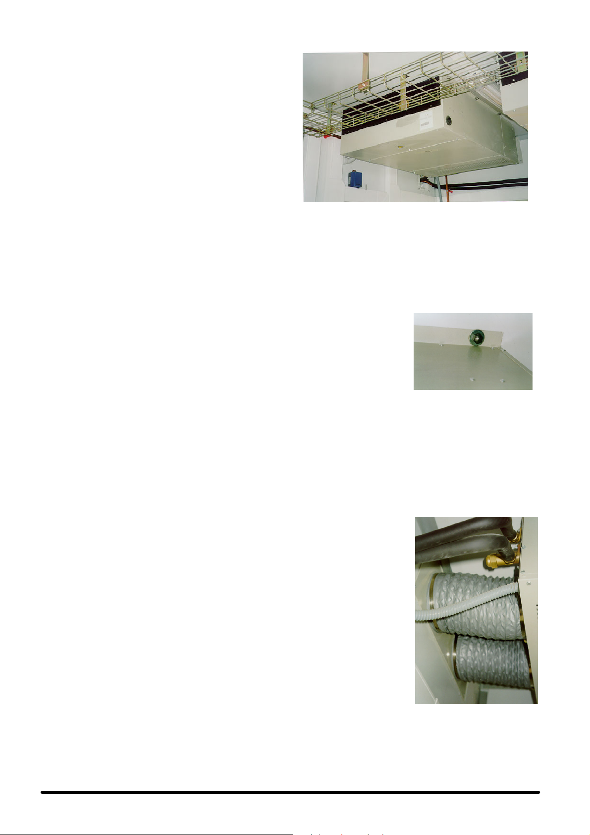
2.3 --- Freecooling duct connections
(optional)
The air conditioner may be
supplied with an integrated
Freecooling device (optional), which uses fresh air from
outside to cool the ambient
without starting up the compressor. The device supplies
the correct cooling capacity
required, through a modulating motor damper.
In this case, the back side of
the unit is equipped with
connections which collect
the outside air, as follows:
S standard: double circu-
lar hole, for 202 (SE
05-- -06) or 252
(S E 08 --- 1 0 --- 1 3 --- 1 4 )
mm diameter flexible
ducts to be fixed with
metal clamps (optional).
S option: single rectangu-
lar hole with flange for
560 x 190 (SE 05 - --06) or 600 x250 (SE 08 ---10---13-- -14)
mm duct (not supplied by us).
Fig. C --- Freecooling ducts
1
English
Page 5
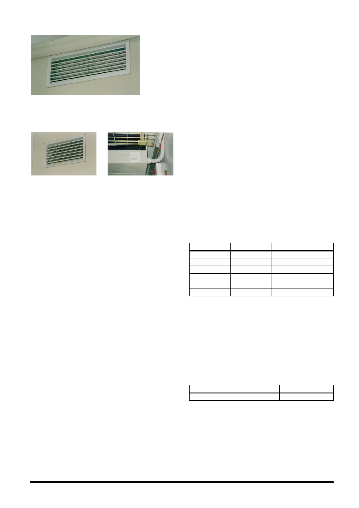
Inbothcases,theholesinthewallhavetobeprotected byrainproof grilles with prefilter (optional), to avoid water or foreign
bodies get in the conditioner.
Fig. D --- External inspectable rainproof grille with prefilter
Outside air, taken into the room by the fan, gets out through an
overpressure damper, which is installed on the walls of the
room (optional) and is protected also by an external rainproof
grille.
Fig. E - -- Internal overpressure damper with outside --- oriented fin
IMPORTANT: The Freecooling damper is lockedby screws, to
avoid damages during the transport. Remove the screws before starting ---up the air conditioner (see warning label on the
rear side of the SE unit).
openings and its outside external waterproof protection
grille.
2.3.1 -- Outer temperature probe installation
Install the outerair temperatureprobe arranged inside theelectric board, at the end of the channel duct.
IMPORTANT: the bulb must be positioned as much outside as
possible and must not be exposed to direct sun rays or weather
agents such as rain or snow. The unit operation could be jeopardized if these precautions are not applied.
2.4 --- Positioning the motor condensing
unit
S The condensing unit must be positioned outside to enable
its cooling (see Fig. 3).
S It is connected to the air conditioner through the refrigerat-
ing lines. Keep refrigerating lines as short as possible (do
not use lines longer than 15 m for R22 and 10 m for R407C).
S To allow for sufficient air flow through the condensing unit
and enough servicing room, the Service Area has to be left
unobstructed, as shown in Fig. 5.
S Install the condensing unit far from polluting agents (eg.
dust, leaves) to ensure the longest efficiency of the unit.
If several locations are availabl e, preferably install the
motor---condensing unit in the place with most reduced direct sun exposure, so as to optimize the performance, and
with a suitable air circulation. Make sure the unit cannot be
completely covered by possible snow. Do not obstruct the
air suction and ejection sections. Position the unit so that
the ejected hot air and the sound emission cannot disturb
people. If the motor---condensing unit is positioned on the
top of building, or on walls exposed to strong winds, provide for a stable fastening, if necessary with additional supports or tie---rods. The wind direction shall be perpendicular to the flow of ejected air. The fastening stability shall be
ensured also in case of earthquakes.
S Fig. 3 shows some examples of how to install the motor
condensing unit.
In case of wall installation, preferably use the optional
fastening kit supplied with the unit, composed for each
motor---condensing unit by a pair of shelves in galvanized
steel, painted with polyester powders in colour RAL 9002
and with smooth finishing, suitable elastomer vibration--damping supports, connection pairs in stainless steels including screw anchors for the wall fastening (see Fig. 4).
NOTE: the screw anchors included in the kit are to be used
only when fastening the shelves on concrete or brick wall
(hollow bricks, too). Do not use on sandwich walls (e.g.
container)or with unknown composition. Inthese cases the
most suitable fastening system for the special material shall
be used. If the above mentioned optional kit is not used,
suitable vibration---damping supports shall anyway be
used between the motor---condensing unit and the
shelves, so as to avoid the vibration diffusion. Also make
sure that the used shelves are suitable for supporting the
motor---condensing unit in safety conditions (e.g. in case of
temporary abnormal loads on the unit).
2.5 --- Refrigeration connections
THIS OPERATION MUST BE CARRIED OUT BY AN EXPERT TECHNICIAN.
The condensing and ambient units have to be charged with refrigerant and they are precharged with nitrogen (see Chap. 6 --R22 units refrigerating charge, or Chap. 7 --- R407C units refrigerating charge).
a) Lines positioning (Fig. 9)
Connect the air conditioner to the condensing unit by using re-
frigerating lines in hard or soft copper .
S Limit the number of preshaped bends; if this is notpossible,
every bend must have a radius of at least 100 mm.
S The gas line must be insulated.
S The liquid line must be kept far from heat sources; if this is
not possible it has to be insulated.
S If the condensing unit is placedabove the evaporating unit,
thelastsegmentoftheintaketube(insulatedtube)must
lean towards the condensing unit.
S If, on the other hand, the condensing unit is placed under
the conditioner it is advisable to create a trap on the intake
tube.
Tab. A -- Standard diameters of R22 a nd R407C
tubes (*)
MODEL GAS DUCT LIQUID DUCT
HISP SE+SC05 φ 14 x 1 φ 8x1
HISP SE+SC06 φ 16 x 1 φ8x1
HISP SE+SC08 φ 18 x 1 φ 10 x 1
HISP SE+SC10 φ 18 x 1 φ 12 x 1
HISP SE+SC13 φ 22 x 1 φ 12 x 1
HISP SE+SC14 φ 22 x 1 φ 12 x 1
(*) For max. (equivalent) distancesup to 15 m for R22 and up to 1o m for
R407C.
b) Draining operation of the refrigerating lines
The draining operation has to be performed by using the 1/4”
SAE connectors, placed on the unit on --- off valves, through the
special quality pump.
2.6 --- Water connections
During the cooling cycle part of the air humidity condenses on
the evaporating coil. The condensate is collected in the tank
placed under the coil and must be drained outside.
Tab. B -- Water connections (Fig. 10)
CONNECTOR DIMENSIONS
Condensate outlet φ 21 mm
To drain the condensate:
S Use galvanized s teel, PVC or flexible polythene tubing.
S CAUTION: DO NOT INTERCONNECT THE OUTLETS OF
DIFFERENT MACHINES.
S Make sure there is at least a 2% gradient towards the drain
outlet.
S There must be a drain trap placed at least 30 mm below
the drain tank.
S Fill the drain trap with water, pouring it into the condensate
tank.
English
2
Page 6
2.7 --- Electric al connections (see Fig. 6,
Fig. 7 and the wiring diagram
supplied with the unit)
1) Before arranging the electrical connections, make sure
that:
S all electrical components are not damaged;
S allterminalscrewsaretight;
S the supply voltage and frequency are as indicated on the
unit.
S the automatic switch QS1 is in open position (OFF);
S there are no live components.
2) Supply cable connections:
S Evaporating unit: the conditioner is supplied with electri-
cal and terminal boards suitable for functioning, through
the Microface integrated microprocessor control.
S Inside the electrical board connect the main supply cable
(not supplied by us) to the knife switch QS1 or to the terminals L1---N (the section of the supply cables is shown in
Tab. 6), by passing through the cable holders on each side
of the unit.
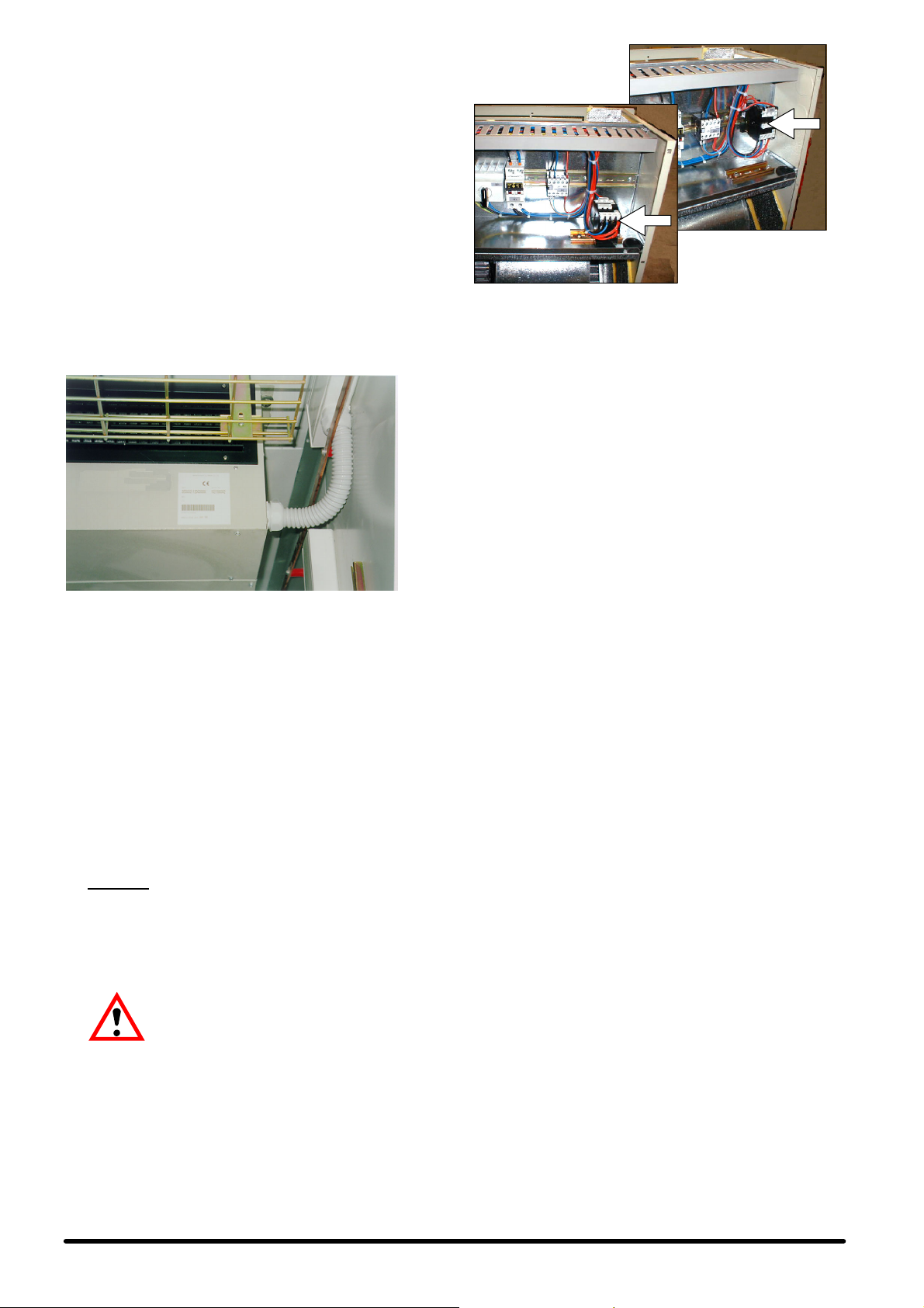
Fig. G --- On ceiling
F i g . H --- O n w a l l
2.8 --- Emergency cooling (optional)
The emergency cooling kit consists of two radial fans at 24 Vdc
or 48 Vdc and of an appropriate electrical board. Supply power
up to 48 Vdc or to 24 Vdc inside the electrical board by means
of a screened cable with a minimum section as shown in
Tab. 7.
3 --- St a r t --- u p
Fig. F --- Details of the SE electrical connections with cable presser
S Connect the Bus control cable between the Microface
S Connect the yellow---green ground cable.
Concerning the alarm contacts available in the different versions, these can be found on the terminal board in the control
panel, and then placed remotely in the display box. For the
alarm description see Chap. 5 and the manual of the installed
control.
S To connect 2 or more units installed in the same room and
S Motor condensing unit:
3) The standard SE evaporating unit is produced for
and plastic sheath (not supplied by us)
board and its remote display, passing through the cable
holders placed on the sides and also in the back of the unit.
provided with the MICROFACE control, with the HIROMATIC interface, use the HIROBUS cable (supplied with the
unit) by connecting it as shown in the wiring diagram. Read
the Microface or Hiromatic manuals to set up the units in
st a n d --- b y.
CAUTION
THE EVAPORATING UNIT. (Read the wiring diagram supplied with the conditioner).
Connect the supply cable and the auxiliaries cable (see
Fig. 7 and Fig.7a) between the terminal board of the conditioner and that of the condensing unit on the other (the
cables are not supplied by us).
90û, releasing it from the metal guide DIN (type “Omega”)
on which it is placed and fastening it on the already arranged guide of the same type (Fig. H). In this way, the
contactor axis will always be horizontal. In the SE unit
equipped with the option DC Emergency Cooling, both
the contactor KM3 and the contactor KM1 (dc fans of the
evaporating section) shall be rotated as indicated above,
using the already arranged second metal supporting guide
: THE CONDENSING UNIT IS SUPPLIED BY
the ceiling installation (Fig. G), but also fits easily
for the wall installation: in this case, the contac-
tor KM3 of the compressor mustbe rotated by
3.1 --- Refrigerating circuit
See Fig. 11 and Fig. 12.
3 . 2 --- F i r s t s t a r t --- u p (o r af t e r lo n g ha l t )
Before starting the air conditioner do check if the power supply
voltage and frequency comply with those indicated on the
identification plate of the unit. After doing that, the conditioner
can be started by putting the automatic switch QS1 ON.
Check the electrical absorption of all components and
compare it with the data shown in the Tab. 3, Tab. 4 and Tab. 5.
Check that there are no active alarms; wait until the system
reaches the standard operation and then make the following
checks:
S that the fans are working correctly;
S that the temperature is guaranteed and the compressor
and heaters work when required;
S that the fan speed adjuster (Variex) of the condensing sec-
tion is correctly calibrated and controls the fan operation
(see Chap. 4).
3 . 3 --- St a r t --- u p w i t h l o w o u t s i d e
temperature
In case of low outside temperature (< 0°C), the unit start---up is
helped by the lag time of the low pressure alarm, within which
the pressures in the refrigerating circuit reach the standard operation values.
3.4 --- Starting and stopping
For the units provided with the MICROFACE control, you can
switch on/off using the main switch QS1, which can be reached
by removing the lower front panel. To start up and stop the unit
turn the QS1 knife switch.
For the units provided with HIROMATIC interface:
S start up the unit by pressing the Hiromatic ON/OFF push
button (confirmed by SYS.ON on the display);
S stop the unit by pressing the Hiromatic ON ---OFF push but-
ton (confirmed by SYS.OFF on the display).
Note: Turn the main switch QS1 off only if the unit is
stopped for a long period of time.
3
English
Page 7

4 --- Op e r a t i o n
4.1 --- General i nformation
The unit operation is completely automatic. The following sequence shows how the unit operates (see also Fig. 11 and
F i g . 1 2 --- Refrigerating circuit):
The temperature sensor, positioned on the intake inside the
room, gives information to the control about the state of the air
to be conditioned.
The control compares the received information with the Set
Point values (= min. indoor temperature required) and the Differential programmed values, presetting the air conditioner for
the air conditioning with the following modes:
4 . 2 --- Co o l i n g (see Fig. 8)
The compressor and the fans are started up when the temperature of the room to be conditioned exceeds the preset value.
The air, taken into the unit through the rear inlet (lower inlet for
unit with Freecoolingoption) by the centrifugal fan, goes immediately through the filter and the evaporator. The cold refrigerant flows trough the evaporator ,cooling the air flowing through
it. The conditioned air is conveyed into the conditioned ambient through the delivery opening. The heat takenfrom theroom
and that generated by the operation of the conditioner motors
are disposed through the condenser placed in the motor --- condensing unit and blown, thanks to the fan, by the outside air.
The condenser fan speed is varied automatically (Variex, see
par. 4.5) as a function of the condensing pressure. For the control operation logic, see Chap. 5.
4.3 --- Heating (optional)
The air heating is achieved through armoured electric heaters
which are located in the air flow and activated according to the
logic set on the control.
The manual reset of the safety thermostat, located on the heaters, is to be carried out by accessing from the air discharge
grille of the evaporating unit.
S QS1 = ON If the main power supply is not cut out, the
emergency system remains inactive; if there is no voltage
on themain powersupply line, some energy is automatically collected from the emergency batteries at 48 V dc (or 24
V dc) and it supplies the fan of the evaporating section and
the electronic control through the 48 V / 230 V (or 24 V dc)
transformer. So all functions of the unit are still managed,
allowing the inside air to recirculate (or the outside air to
flow in, if the unit is provided with the Freecooling system)
if the temperature inside the room is not within the permitted range.
5 --- Microprocessor controls
The machine is available in four different operating configurations:
1) only cooling unit;
2) cooling and heating unit;
3) unit with freecooling, only cooling;
4) unit with freecooling, cooling and heating.
In all versions the controldisplay is remoted on the metal box to
be installed inside the room.
5.1 --- Cooling only unit
5.1.1 -- Control logic
This option is managed by the Microface microprocessor control, which can be combined with the Hiromatic control to monitor all the operation parameters of the unit (see the enclosed
manual). The control algorithm is based on a one---step adjustment for the compressor - --aided cooling: the control manages
all its lags in the activation, so as to guarantee its correctoperation and to make it function as long as possible.
PBand
Cooling only unit
4.4 --- Freecooling (optional)
When the temperature of the outsideair is lower than that of the
inside air by some degrees, it is possible to use this difference
to refresh the inside of the room by direct intake of the outside
air, i.e. without using the compressor. Thus it is possible to
achieve a considerable energy saving.
When the expected conditions occur, the servo-- -control, managed by the Microface control, opens the moving damperseparating the flow of the inside air and outside air. Outside air,taken into the room by the fan, gets out through an overpressure
damper which is installed on the walls of the room (optional)
and is protected by an external rainproof grille.
The opening degree of the damper is determined as a function
of the set point value to be kept and of the intake air temperature (see Chap. 5).
4.5 --- Adju st me n t of the con de n se r fan
speed
A sensor is positioned so as to detect constantly the condensing pressure of the refrigerating gas. On the basis of this information, an electronic device (Variex) adjusts the fan rotation
speed in order to keep the condensing pressure within the allowed values. In this way, besides optimizing the compressor
operation, you can have a remarkable reduction of the sound
pressure level (mainly during the night), an easier start---up of
the compressor at low temperatures and some energy saving.
For the calibration of the speed adjuster see chapter 8.
4.6 --- Emergency cooling (optional)
This option is available for all those applications where it is important to keep an airflow inside the room even in the event of a
mains power cut - --out. In this case the units can be supplied by
the emergency batteries at 48 V dc (or 24 V dc).
The intervention mode of the emergency system depends on
the state of the automatic switch QS1:
Set Cooling °C
Fig. I --- Operation of the cooling only unit.
5.1.2 -- Start--Stop
There are 2 ways for starting or stopping the unit:
a) the digital input of the Microface card;
b) the ON --- OFF push button on the Hiromatic interface (op-
tional).
Priority with Hiromatic: a) and b) must be regarded as 2 series
contacts; the unit can operate only if all contacts are on.
5.1.3 -- Alarm control
The 2 alarm contacts available on the terminal board of the control panel can be used in this way:
1) General alarm:
S compressor low pressure
S compressor high pressure (reset on the pressure switch)
S sensor fault
S memory fault
S fan fault
2) General warning --- signalling of various abnormal conditions, among which:
S high temperature
S low temperature
Notes:
S both the alarm and the warning must be reset manually on
the Microface.
S An alarm causes the unit to stop and the unit in stand-- -by
(if available) to intervene.
S The warning doesn’t cause the unit to stop.
English
4
Page 8

5.1.4 -- Optional alarm card
Besides the components described for the standard configuration, on the alarm card --- which can be supplied as optional -- there are relay contacts to have the following alarms sepa-
rated:
1) Compressor high and low pressure
2) High temperature
3) Low temperature
4) Dirty filter alarm (if installed)
5) Fan fault
These alarms cause the unit to stop in the same ways as de-
scribed in the previous paragraph.
For a complete description of the alarms see the encl. Microface manual.
5.1.5 -- Unit in stand--by
The control of the unit in stand-- -by is completely automatic
thanks to the possibility of connecting the Microface control. A
unit in stand --- by starts in the event of an alarm stopping the
main unit; this occurs even if the main unitis switched off or disappears from the system, due to a fault on the control connecting bus. The rotation of the units in stand -- -by occurs automatically every 24 hours, so as to allow a homogeneous wear of the
system components.
If the system is connected to the Hiromatic interface, it is possible to set a different rotation control.
If several units are simultaneously working with the same set
point, the temperature used for the controlis the average of the
detected ones; further, in the operation with compressor, the
proportionalband is divided in as many parts as twice the number of units belonging to the system, so asto shut the totalavailable refrigerating capacity.
5.3 --- Unit with Freecooling
5.3.1 -- Control logic
This option is also managed by the Microface microprocessor
control, which can be combined with the Hiromatic control to
monitor all the operation parameters of the unit (see the enclosed manual). The control algorithm is based on a one---step
adjustment for the compressor--- aided heating and cooling
and on an adjustment of a Proportional --- Integrative type for
cooling in the Freecooling mode with setting of the set point
and proportional band (P) (Fig. K).
The control manages all its lags in the activation of the compressor, as seen in the two preceding cases, so asto guarantee
its correct operation and to makeit function aslong as possible.
The Freecooling mode is activated depending on the difference (which can be set) between the internal and the external
temperatures. This means that if the difference between the 2
temperatures increases beyond a certain value, the unit automatically passes to the Freecooling function:thecompressoris
de---activated and the analog output controls the 3 - --point servomotor of the damper. The damper opening is determined as
a function of the difference between the outside and inside
temperatures and as a function of the intake air temperature,
which cannot be lower than a preset safety value.
If the inside temperature exceeds the proportional band by
more than 20% for over 10 minutes, the unit shifts to the compressor--- aided cooling and the Freecooling mode remains
de---activated for ½ hour. If the inside temperature exceeds the
proportional band by more than 50% for over 2 minutes, the
Freecooling mode is de ---activated for ½ hour, and the unit
shifts to cooling by means of the refrigerating compressor.
Dead band!P@ Pband !P@ Pband
Freecooling
mode
5.2 --- Cooling and heating unit
5.2.1 -- Control logic
The control algorithm is based on a one -- -step adjustment for
the compressor --- aided heating and cooling.
The control manages all its lags in the activation of the compressor, as previously described, so as to guarantee its correct
operation and to make it function as long as possible.
Dead band!P@ Pband !P@ Pband
Cooling and
heating unit
Heating
Fig. J --- Operation of the cooling + heating unit
5.2.2 -- Start--Stop
See Par. 5.1.2.
5.2.3 -- Alarm control
See Par. 5.1.3.
A further general warning is available signalling the following
abnormal condition:
S heater thermostat (reset on the thermostat).
Notes:
S the warning doesn’t cause the unit to stop.
S In case the safety heater thermostat intervenes, the reset
must be carried out on the thermostat, following the same
instructions as before.
5.2.4 -- Optional alarm card
See Par. 5.1.4.
5.2.5 -- Unit in stand--by
See Par. 5.1.5.
Set Cooling °C
Set
CoolingHeating °C
Dead band!P@ Pband !P@ Pband
Comprescooling mode
sor
Set
CoolingHeating °C
Fig. K - -- Operation of compressor, electric heaters and opening of
the Freecooling damper
5.3.2 -- Start--Stop
There are 2 ways for starting or stopping the unit:
a) the digital input of the Microface card;
b) the ON --- OFF push button on the Hiromatic interface (op-
tional).
Priority with Hiromatic: a) and b) must be regarded as 2 series
contacts; the unit can operate only if all contacts are on.
5.3.3 -- Alarm control
The 2 alarm contacts available on the terminal board of the control panel can be used in this way:
1) General alarm:
S compressor low pressure
S compressor high pressure (reset on the pressure switch)
S sensor fault
S memory fault
S fan fault
2) General warning --- signalling of various abnormal conditions, among which:
S high temperature
S low temperature
S heater thermostat (reset on the thermostat).
5
English
Page 9

Notes:
S both the alarm and the warning must be reset manually on
the Microface.
S An alarm causes the unit to stop and the unit in stand---by
(if available) to intervene. If the unit is in stand---alone, the
high and low pressure alarms don’t stop the machine to allow the operation in Freecooling mode in the proper conditions.
S The warning doesn’t cause the unit to stop.
S In case the safety heater thermostat intervenes, the reset
must be carried out on the thermostat, following the same
instructions as before.
5.3.4 -- Optional alarm board
Besides the components described for the standard configuration, on the alarm card --- which can be supplied as optional -- there are relay contacts to have the following alarmsseparated:
1) Compressor high and low pressure
2) High temperature
3) Low temperature
4) Dirty filter alarm (if installed)
5) Fan fault
These alarms cause the unit to stop in the same ways as de-
scribed in the previous paragraph. For a complete description
ofthealarmsseetheencl.Microfacemanual.
5.3.5 -- Unit in stand--by
The control of the units in stand ---by is completely automatic,
thanks to the possibility of connecting the Microface control. A unit
in stand--- by starts in case an alarm stops the main unit; this occurs even if the main unit is switched off or disappears from the
system, due to a fault on the control connecting bus.
The rotation of the units in stand---by occurs automatically every
24 hours, so as to allow a homogeneouswear of the system components. If the system is connected to the Hiromatic interface, it is
possible to set a different rotation control. If several units are simultaneously working with the same set point, the temperature used
for the control is the average of the detected ones; further, in the
operation with compressor, the proportional band is divided in as
many parts as twice the number of units belonging to the system,
so as to shut the total available refrigerating capacity . The operation in the Freecooling mode is homogeneous and simultaneous
on all units.
The Fig. L), shown as an example, describes the operation of a
system consisting of 3 units.
Freecooling mode
Dead band!P@ Pband !P@ Pband
6 --- R22 units refrigerant
charge
CAUTION: THESE OPERATIONS MUST BE PERFORMED
BY AN EXPERT TECHNICIAN.
THE UNIT, AS SUPPLIED, IS PRECHARGED WITH
GEN.
6.1 --- Characteristic s of the refrigerant
fluid R22
At standard temperature and pressure it is a colourless gas
with low toxicity, non---flammable, and it has an allowed exposure limit value (AEL/TLV) corresponding to 1000 ppm (average value measured on 8 hours per day). In the event of leakage, air the room before use.
6.2 --- Refrigerant charge R22
WHEN REPAIRING THE REFRIGERATION CIRCUIT,
PLEASE COLLECT ALL REFRIGERANT IN A CONTAINER:
DO NOT DISPOSE OF IT IN THE ENVIRONMENT.
1) After connecting the refrigerating lines to the main paths of
the valves, placed on the evaporating and motor condensing units, discharge the precharged nitrogen by operating
on the ¼” SAE tap, with needle valve, of the motor condensing unit.
2) Empty the circuit with the special (quality) vacuum pump,
applying a vacuum of 0.7 absolute mbar.
3) After 3 hours check not to have exceeded 1.3 absolute
mbar. If the vacuum is not kept there are leaks. Repair the
circuit and repeat the operations from point 2.
4) Connect the charge cylinder to the liquid line of the motor
condensing and start charging the amount of refrigerant
R22 as shown in Tab. C.
Tab. C -- Refrigerating charge R22 for a 5 m dis-
tance between the evaporating and motor condensing units.
MODEL Refrigerating charge R22 (kg)
Hisp SE+SC05 2.2
Hisp SE+SC06 2.5
Hisp SE+SC08 4.3
Hisp SE+SC10 4.4
Hisp SE+SC13 4.4
Hisp SE+SC14 4.4
NITRO-
1
2
3
Set °CCoolingHeating
Compressor cooling mode
Dead band!P@ Pband !P@ Pband
11
223
3
Set °CCoolingHeating
1 = main unit
2 = unit in stand --- by
3 = unit in stand --- by
F i g . L --- A s y s t e m c o n s i s t i n g o f 3 u n i t s , 2 o f w h i ch i n s t an d --- b y ---
Microface control
5) In case it is impossible to complete charging shift the cylin-
der mode to compressor intake and complete charging or
however, after charging, operate as follows:
6) Start up the unit as shown in par. 3.2.
7) Start the compressor manually.
8) Guarantee a constant condensation temperature (prefer-
ably 50°C); if necessary, partially obstruct the condenser
exchange surface to obtain these conditions.
9) Wait until the operating conditions of the whole refrigeration
circuit are normal.
10) Make sure, while the system is in standard operation, that
the superheating complies with following values (Tab. D:
manometric temperatures are shown).
Tab. D -- R22: Superheating table
Internal temperature °C 24 27
Internal relative humidity %RH 50 50
Compresor superheating °C 8 12
Values applying with condensation T = 50°C
For refrigerating line distances between 5 and 15 m, increase
the charge of the circuit as shown in the following Tab. E.
English
6
Page 10

Tab. E -- Additional charge of R22 refrigerant ev-
ery metre of additional distance (between 5 and 15 m)
liquid line diameter
8 mm (outer side of the line) 30
10 mm (outer side of the line) 53
12 mm (outer side of the line) 70
Values applying with condensation T = 50°C
NOTE: Under distance is meant the length of the liquid line, including the bends, between the internal and the external units
(do not sum inlet and outlet).
R22 refrigerant
charge (g/m)
6 . 3 --- Oi l c h a r g e
The oil to be used when topping up is SUNISO3GS; if SUNISO
3GS is unavailable use an oil with the same characteristics(see
Tab. F).
NEVER MIX DIFFERENT OILS TOGETHER. CLEAN THE PIPING COMPLETELY BEFORE CHANGING THE TYPE OF OIL
USED.
Tab. F -- Suniso 3GS oil (standard)
approx. specific weight (at 15_C)
flash point (C.O.C.)
pour point
ENGLER viscosity at 50 _C
viscosity index
copper corrosion (100 _C, 3 hours) ASTM D130
neutralization value
conradson carbon residue
dielectric strength
:
0.91 kg/l
:
170 _C
:
--- 4 0 _C
:
2.7 E
:
0
:
1
:
0.03 max.
:
0%
:
>30kV
Tab. G -- RefrigeratingchargeR407C for a 5 m dis-
tance between the evaporating and motor condensing units.
MODEL Refrigerating charge R407C (kg)
Hisp SE+SC05 2.2
Hisp SE+SC06 2.5
Hisp SE+SC08 4.3
Hisp SE+SC10 4.4
Hisp SE+SC13 4.4
Hisp SE+SC14 4.4
5) In case it is impossible to complete charging shift the cylinder mode to compressor intake and complete charging or
however, after charging, operate as follows:
6) Start up the unit as shown in par. 3.2.
7) Start the compressor manually.
8) Guarantee a constant condensation temperature (preferably 50°C); if necessary, partially obstruct the condenser
exchange surface to obtain these conditions.
9) Wait until the operating conditionsof the whole refrigeration
circuit are normal.
10) Make sure, while the system is in standard operation, that
the superheating complies with following values (Tab. H:
manometric temperatures are shown).
Tab. H -- R407C: Superheating table
Internal temperature °C 24 27
Internal relative humidity %RH 50 50
Compresor superheating °C 8 12
Values applying with condensation T = 50°C
For refrigerating line distances between 5 and 10 m, increase
the charge of the circuit as shown in the following Tab. I.
7 --- R407C units refrigerant
charge
CAUTION: THESE OPERATIONS MUST BE PERFORMED BY
AN EXPERT TECHNICIAN.
THE UNIT, AS SUPPLIED, IS PRECHARGED WITH
GEN.
7.1 --- Characteristic s of the refrigerant
fluid R407C
At standard temperature and pressure it is a colourless gas
with low toxicity, non---flammable, and it has an allowed exposure limit value (AEL/TLV) corresponding to 1000 ppm (average value measured on 8 hours per day). In the event of leakage, air the room before use.
7.2 --- Refrigerant charge R407C
WHEN REPAIRING THE REFRIGERATION CIRCUIT,
PLEASE COLLECT ALL REFRIGERANT IN A CONTAINER:
DO NOT DISPOSE OF IT IN THE ENVIRONMENT.
1) After connecting the refrigerating lines to the main paths of
the valves, placed on the evaporating and motor condensing units, discharge the precharged nitrogen by operating
on the ¼” SAE tap, with needle valve, of the motor condensing unit.
2) Empty the circuit with the special (quality) vacuum pump,
applying a vacuum of 0.3 absolute mbar.
3) After 3 hours check not to have exceeded 1.3 absolute
mbar. If the vacuum is not kept there are leaks. Repair the
circuit and repeat the operations from point 2. .
4) Connect the charge cylinder to the liquid line of the motor
condensing and start charging the amount of refrigerant
R407C as shown in Tab. G.
NITRO-
Tab. I -- Additional charge of R407C refrigerant
every metre of additional distance (between 5 and 10 m)
liquid line diameter
8 mm (outer side of the line) 30
10 mm (outer side of the line) 53
12 mm (outer side of the line) 70
Values applying with condensation T = 50°C
NOTE: Under distance is meant the length of the liquid line, including the bends, between the internal and the external units
(do not sum inlet and outlet).
R407C refrigerant
charge (g/m)
7 . 3 --- Oi l c h a r g e
The oil to be used when topping up is MOBIL EAL ARCTIC
22CC; if MOBIL EAL ARCTIC 22CC is unavailable use an oil
with the same characteristics (see Tab. J).
NEVER MIX DIFFERENT OILS TOGETHER. CLEAN THE PIPING COMPLETELY BEFORE CHANGING THE TYPE OF OIL
USED.
Tab. J -- Mobil Eal Arctic 22CC oil (standard)
approx. specific weight (at 15_C)
flash point (C.O.C.)
pour point
viscosity index
viscosity at 40_C
viscosity at 100_C
It is therefore obvious that the taps of the compressormustonly
be turned after the whole plant has been subjected to a vacuum and partial filling.
:
0.99 kg/l
:
245 _C
:
< --- 5 4 _C
:
116
:
23.6 cST
:
4.7 cST
7
English
Page 11

8 --- Calibrations
The air conditioner has already been factory---tested and calibrated as described below.
COMPONENT
Low pressure switch
(LP)
CALIBRATIONS NOTES
STOP : 1 bar
START : 2 bar
(fixed calibrations)
automatic
reset
High pressure switch
(HP)
Fan speed adjuster
(BV)
STOP : 28 bar
START : 20 bar
(fixed calibrations)
SET. : 18.8 bar
BAND P : 3.8 bar
(For adjusting see the instructions enclosed on the machine)
manual reset
pressing the
push button
9 --- Maintenance / Spare parts
For safety reasons, if possible, cut the unit out, by operating the QS1 switch before carrying out any maintenance.
The Maintenance Programme described below should be carried out by a skilled technician, preferably working under a maintenance contract.
Maintenance programme --- Monthly check
Check that the fan motor rotates freely without any abnormal noise, and ensure that the
FANS
AIR FILTERS
ELECTRICAL CIRCUIT
REFRIGERATING CIRCUIT
bearings are not running hot.
Also check the current absorption.
Check the state of the filter; if necessary clean or replace it.
To replace it:
S remove the lower panel of the unit
S extract the filter from its seat vertically
S fit the spare part
S close the panel
In very dusty environments perform this check more frequently.
S Check the power supply on all phases.
S Ensure that all electrical connections are tight.
S Check the evaporating pressures (to be done by an expert technician).
S Check the compressor current absorption, its head temperature and the presence of
any unusual noise.
S Ensure that there is no ice formation on the evaporator.
9 . 1 --- Di s m a n t l i n g t h e u n i t
The machine has been designed and built to ensure a continuing operation. The working life of some of the main components, such as the fan and the compressor, depends on their
maintenance. If the unit has to be dismantled, this must be
done by skilled refrigerator technicians.
The refrigerating fluid and the lubricating oil, contained in the
circuit, must be collected according to the laws of your Country.
English
9.2 --- Spare parts
It is recommended the use of original spare parts.
When placing an order referto “ComponentList” enclosedwith
the machine and quote the unit model no. and serial no.
8
Page 12

10 --- Appendix
10.1 --- Check the unit after the installation
The following list includes the checks to carry out to verify that Hisp is intact after the installation.
IMPORTANT: EVERY UNIT IS TESTED IN OUR PLANTS BEFORE DELIVERY.
A) STATIC CHECK
A.1) Evaporating unit S E
A.1.a) Sight check that the panels and rivets are in-
tact and well fixed.
A.1.b) Check that a condensate drain, with a wide---
bended trap, for every machine is available.
A.1.c) Check that the (optional) Freecooling air in-
take ducts (rigid or flexible) and the rainproof
external grille, with metallic prefilter (optional)
are available and fixed.
A.1.d) Check that the overpressure damper for the
outlet of the Freecooling air is available and
functions correctly (the fins are mobile), together with the externalrainproof grille. (Freecooling is optional)
A.1.e) Check that the unit is fixed firmly to the ceiling
or to the wall, and that any fastening devices
passing along the walls of the room to be conditioned are sealed.
A.1.f) Put the electrical board of the room in the
”OFF” position.
A.1.g) Remove the lower inspection panels to gain
access to the inside of the evaporating unit.
A.1.h) Gain access to the electrical board and put
the QS1 mains supply switch in the ”0” position.
A.1.i) Checkthat the electrical boardis free from for-
eign bodies.
A.1.l) Chec k that the supply cables and the Bus
cable between Microface and remote display
are correctly connected.
A.1.m) Check the fastening and the polarity of the
emergency supply (batteries) cables to the inverter. If in doubt, read the wiring diagram.
CAUTION: do not alter the adjustment of the
potentiometers in the inverter board.
A.1.n) Check the fastening of cables, electronic
components and fuses.
A.1.o) Check the evaporating fan by turning it manu-
ally:itmustbefreetorotatewithoutanyab-
normal noise. The shaft must be in line.
A.1.p) Check the correct position of the air filter.
A.1.q) Check that the Freecooling damper (if
installed) is intact and fastened.
A.1.r) Check that the delivery fins are oriented, de-
pending on your needs.
A.1.s) Check that the (optional) electric heaters are
correctly placed in the air flow, and that they
do not touch the conditioner’s walls or other
components.
A.2) SC motor condensing unit
A.2.a) Remove the front and side panels to gain ac-
cess to the refrigerating circuit (when the
weather conditions allow it: prevent water
from entering into the electrical board and the
compressor compartment).
A.2.b) Check that the refrigerating circuit is intact
and that there are no oil stains in the compres-
sor compartment and along the ducts.
A.2.c) Check the evaporating fan by turning it by
means of a screwdriver: it must be free to ro-
tate without any abnormal noise.
A.2.d) Check that the electrical board is free from for-
eign bodies, the correct connection to the
evaporating unit and that all electrical con-
nections are tightened.
The unit is ready for the dynamic check.
B) DYNAMIC CHECK
B.1) Close the inspection panels of the evaporat-
ing unit, with the exception of the panel letting
into the electrical board.
B.2) Check the ground connection.
B.3) Put the electrical board of the room in the
”ON” position.
B.4) Gain access to the electrical board of the
evaporating unit and put the QS1 mains sup-
ply switchinthe”1”position.
B.5) Check the voltage at the main supply cables.
B.6) Check the voltage at the emergency supply
cables.
B.7) Set the required syst em configuration by
means of the Microface (or Hiromatic) control
display,such as set point, network (by assign-
ing an identification number to every unit), pa-
rameter sharing, stand ---by, Freecooling (if
installed) differentials and so on.
B.8) Start up the machine and measure the current
absorbed by the evaporating fan only.
B.9) Start up the compressor (if necessary force
the system via the control) and wait until the
system is stable. Measure the absorbed cur-
rent,withbothfanandcompressoroperating.
B.10) Check all these values by comparing them
with the OAs (Operating Ampère) as speci-
fied in this Manual in order to avoid abnormal
electric absorptions.
B11) Check the delivery temperature with a digital
thermometer.
B.12) Verify the superheating, according to Tab. 10.
B.13) (If the emergency power supply option is
available) disconnect the mains supply (via
the electrical board of the room) and check
that the inverter starts automatically.
B.14) Restore the correct calibration of the control
parameters.
B.15) Close the panels of the evaporating and mo-
tor condensing units.
9
English
Page 13

Avvertenze
Si raccomanda:
S di conservare il manuale per tutto il periodo di vita della macchina
S di leggere con attenzione il manuale prima di qualsiasi operazione sulla macchina
S di impiegare la macchina esclusivamente per lo scopo per cui è stata progettata; l’uso improprio dell’unità esonera
il costruttore da qualsiasi responsabilità.
Il manuale è rivolto all’utente finale per le sole operazioni eseguibili con pannelli chiusi.
Le operazioni che necessitano dell’apertura di pannelli con attrezzi devono essere eseguite solo da personale esperto.
Ogni macchina è munita di dispositivo di sezionamento elettrico che consente all’operatore di intervenire in condizioni di
sicurezza. Tale dispositivo deve essere sempre usato per eliminare i pericoli durante la manutenzione (scosse elettriche,
scottature, ripartenza automatica, parti in movimento e controllo remoto).
La chiave data in dotazione da Hiross che permette le rimozione dei pannelli deve essere conservata dal personale addetto alla manutenzione.
Per identificare la macchina (modello e numero di serie), in caso di richiesta di assistenza o di ricambi, leggere la targhetta
di identificazione posta esternamente od internamente all’unità.
ATTENZIONE: questo manuale, in quanto preliminare, è soggetto a modifiche; pertanto, ai fini di una completa ed aggiornata informazione, l’utente dovrà consultare il manuale a bordo della macchina.
Indice
1 --- Operazioni preliminari 1......................................................................
1. 1 --- P r e m e s s a 1......................................................................................
1. 2 --- I s p e z io n e 1.......................................................................................
1. 3 --- Tr a s po r t o 1.......................................................................................
1.4 --- Impermeabilità dell’ambiente 1.....................................................................
1.5 --- Limiti di funzionamento 1...........................................................................
1.6 --- Aree di servizio 1..................................................................................
2 --- In s t a l l a z i o n e 1...............................................................................
2.1 --- Dimensioni di ingombro 1..........................................................................
2.2 --- Posizionamento dell’unità ambiente 1...............................................................
2.3 --- Collegamenti condotti di Freecooling (opzionale) 1....................................................
2.4 --- Posizionamento dell’unità motocondensante 2........................................................
2.5 --- Collegamenti frigoriferi 2...........................................................................
2.6 --- Collegamenti idraulici 2............................................................................
2.7 --- Collegamenti elettrici (ved. Fig. 6, Fig. 7 e schema elettrico fornito con l’unità) 3..........................
2.8 --- Raffreddamento di emergenza (opz.) 3..............................................................
3 --- Av v i a m e n t o 3................................................................................
3.1 --- Circuito frigorifero 3...............................................................................
3.2 --- Primo avviamento (o dopo una lunga interruzione) 3..................................................
3.3 --- Avviamento con bassa temperatura esterna 3........................................................
3.4 --- Avviamento e fermata 4............................................................................
4 --- Funzionamento 4.............................................................................
4.1 --- Generalità 4......................................................................................
4.2 --- Raffreddamento (ved. Fig. 8) 4......................................................................
4.3 --- Riscaldamento (opzionale) 4.......................................................................
4.4 --- Raffreddamento in Freecooling (opzionale) 4.........................................................
4.5 --- Regolazione della velocità del ventilatore del condensatore 4...........................................
4.6 --- Raffreddamento di emergenza (opz.) 4..............................................................
5 --- Controlli a microprocessore 4.................................................................
5.1 --- Unità solo freddo 4................................................................................
5.2 --- Unità freddo e caldo 5.............................................................................
5.3 --- Unità con freecooling 5............................................................................
6 --- Carica refrigerante R22 6.....................................................................
6.1 --- Caratteristiche del fluido frigorigeno R22 6...........................................................
6.2 --- Carica refrigerante R22 6...........................................................................
6.3 --- Carica olio 7......................................................................................
7 --- Carica refrigerante R407C 7...................................................................
7.1 --- Caratteristiche del fluido frigorigeno R407C 7.........................................................
7.2 --- Carica refrigerante R407C 7........................................................................
7.3 --- Carica olio 8......................................................................................
8 --- Tarature 8....................................................................................
9 --- Ma n u t e n z i o n e / R i c a m b i 8.....................................................................
9.1 --- Smantellamento dell’unità 8........................................................................
9. 2 --- Ri c a m bi 8........................................................................................
1 0 --- A p p e n d i c e 9..................................................................................
10.1 --- Verifica dell’unità dopo l’installazione 9..............................................................
Page 14

1 --- Operazioni preliminari
1 . 1 --- Pr e m e s s a
Il seguente manuale riguarda l’installazione, il funzionamento
e la manutenzione del Condizionatore d’aria HISP, composto
da un’unità evaporante (SE, Split ---Evaporante) posta in ambiente e da un’unità condensante (SC, Split --- Condensante)
posta all’esterno.
IMPORTANTE:
Consultare anche il manuale del controllo Microface fornito
con la macchina (se installato):
1 . 2 --- Is p e z i o n e
Al ricevimento della macchina controllare immediatamente il
suo stato; contestare subito alla compagnia di trasporto qualsiasi eventuale danno.
1 . 3 --- Tr a s p o r t o
S Tenere sempre l’unità condensante in posizione verticale e
non lasciarla all’aperto.
S Durante il trasporto evitare di esercitare pressione sugli an-
goli superiori dell’imballaggio.
S Disimballare le unità il più vicino possibile al luogo dell’ins-
tallazione. Una volta disimballate evitare urti che possono
essere trasmessi ai componenti interni.
1.4 --- Impermeabilità dell’ambiente
Per creare stabili condizioni termoigrometriche nell’ambiente,
procedere nel modo seguente:
S Creare una barriera vapore per le pareti, il pavimento e il
soffitto con materiale impermeabile.
S Assicurarsi che la stanza sia isolata dall’esterno sigillando
le aperture, le entrate dei cavi, ecc.
1.5 --- Limiti di funzionamento
Le unita’ sono previste per funzionamento all’interno dei campi
di lavoro(ved.Tab. 1). Talilimiti sono intesi per macchine nuove
correttamente installate o per le quali si sia effettuata una corretta manutenzione. Le clausole di garanzia non sono valide
per ogni possibile danneggiamento o malfunzionamento che
puo’ verificarsi durante od in conseguenza di operazioni al di
fuori dei valori di applicazione.
1.6 --- Aree di servizio
L’unità deve essere provvista di un’area di servizio adatta,
come segue (ved. Fig. 3 e Fig. 5).
Tutta la manutenzioneall’unità evaporante può essererealizzata dalla parte inferiore, tramite tre pannelli removibili per accesso al quadro elettrico, alla sezione evaporante e ventilante, ed
allasezionefiltranteediFreecooling (se installato).
L’accesso all’unità motocondensante è garantito da pannelli
removibili fissati con viti antivandalismo (l’apposito utensile è
fornito con l’unità).
2 --- In s t a l l a z i o n e
ATTENZIONE:
L’unità ambiente non deve mai essere installata all’esterno.
2.1 --- Dimensioni di ingombro
Si vedano le Fig. 1 e Fig. 2 per le dimensioni di ingombro
dell’unità evaporante (SE) e dell’unità esterna motocondensante (SC).
F i g . A --- U n i t à e va p o r a n t e S E
2.2 --- Posizionamento dell’unità ambiente
S Disimballare le unità il più vicino possibile al luogo dell’ins-
tallazione. Una volta disimballate evitare urti che possono
essere trasmessi ai componenti interni.
S Il condizionatore d’aria (unità ambiente) può essere collo-
cato in qualsiasi ambiente chiuso purché questo non sia
aggressivo.
S Posizionare l’unita’ ambiente vicino alla fonte principale di
calore.
S Fissare l’unità al soffit-
to o a parete utilizzando 6 (SE 05 - -- 06) o 8
(S E 0 8 --- 1 0 --- 1 3 --- 1 4 )
fissaggi ad espansione o passanti (in tal
caso garantire la tenuta stagna del fissaggio) in corrispondenza
dei fori φ 8mmposti
sulle due staffe laterali.
S Assicurarsi che il flusso d’aria circoli liberamente.
S Per consentire la manutenzione delle unità e’ necessario
lasciare libera da ostruzioni l’Area di Servizio in Fig. 5 (Con
riferimento alla Fig. 5c, la distanza minima di 200 mm sul
retrodell’unità evaporante è indicativa, per consentire il collegamento frigorifero con l’unità motocondensante).
Fig. B --- Fig. B: Dettaglio del fissaggio
2.3 --- Collegamenti condotti di
Freecooling (opzionale)
Il condizionatore d’aria può
essere fornito con dispositivo di Freecooling integrato
(opzionale), che utilizza l’aria frescaesterna per raffreddare l’ambiente senza attivare il compressore, mediante una serranda motorizzata modulante, così da
fornire l’esatta capacità frigorifera richiesta. L’unità
viene fornita in tal caso con il
lato posteriore predisposto
per la ripresa dell’aria esterna tramite i seguenti collegamenti possibili:
S standard: doppio foro di
sezione circolare, per
manichette flessibili di
diametro 202 (SE
05-- -06) o 252 (SE
08-- -10---13---14) mm, da
fissare con fascette metalliche (opzionali).
S opzione: singolo foro di sezione rettangolare con flangia
per condotto rigido 560x190 mm (SE 05-- -06) o 600x250
m m ( S E 0 8 --- 1 0 --- 1 3 --- 1 4 ) ( n o n f or n i t o d a n o i );
Fig. C --- Condotti di Freecooling
1
Italiano
Page 15

In ambedue i casi, i fori praticati nella parete dovranno essere
protetti da apposite griglie antipioggia munite di prefiltro (opzionale), per evitare l’ingresso di acqua o corpi estranei nel
condizionatore.
Fig. D --- Griglia esterna antipioggia ispezionabile con prefiltro
L’aria esterna, aspirata dal ventilatore ed affluita all’interno del
locale ne fuoriesce attraverso una serranda di sovrapressione
installata sulle pareti del locale stesso (opzionale), e protetta
anch’essa da un’apposita griglia esterna antipioggia.
Fig. E --- Serranda di sovrapressione interna con apertura alette verso
IMPORTANTE: La serranda di Freecooling è bloccata con viti,
per evitarne il danneggiamento durante il trasporto. Le viti vanno rimosse prima dell’avviamento del condizionatore (si veda
la relativa etichetta informativa sul retro dell’unità SE):
l’esterno e relativa griglia esterna antipioggia antivolatile
2.3.1 -- Installazione sonda di temperatura esterna
Installare la sonda di temperatura aria esterna predisposta
all’interno del quadro elettrico, alla estremità del condotto di
canalizzazione.
IMPORTANTE: Il bulbo deve essere posizionato il più esternamente possibile e non deve essere colpito da raggi solari o sottoposto a intemperie quali pioggia o neve.La non applicazione
di queste precauzioni potrebbe compromettere il funzionamento dell’unità.
S La Fig. 3 mostra con alcuni esempi come posizionare l’u-
nità motocondensante. In caso di installazionea parete, utilizzare di preferenza il kit opzionale di fissaggio fornito con
l’unità, composto per ciascuna motocondensante da una
coppia di mensole in acciaio zincato verniciate con polveri
poliestere di colore RAL 9002 e finitura liscia, opportuni
supporti antivibranti in elastomero, minuteria di collegamento in acciaio inox comprensiva di tasselli ad espansione per fissaggio a parete (ved. Fig. 4).
NOTA: i tasselli ad espansione forniti nel kit sono da utilizzarsisoloincasodifissaggiodellemensolesuparetiincemento o laterizio (incluso il caso di mattoni forati). Non utilizzare su pareti sandwich (ex. container) o di cui non si
conosca la composizione. In questi casi andrà adottato il
sistema di fissaggio più idoneo per lo specifico materiale.
Qualoranonvengautilizzatoilkitopzionalesopradescritto, dovranno comunque essere sempre previsti appositi
supporti antivibranti tra la motocondensant ee le mensole,
in grado di evitare la propagazione di vibrazioni. Assicurarsi inoltre che le mensole utilizzate sianoidonee a sostenere
l’unità motocondensante in condizioni di sicurezza (ex. in
caso di temporanei carichi anomali gravanti sulla stessa).
2.5 --- Collegamenti frigoriferi
QUESTA OPERAZIONE DEVE ESSERE ESEGUITA DA UN
FRIGORISTA ESPERTO.
L’unità condensante e l’unità ambiente arrivano precaricate di
azoto e devono essere caricate con refrigerante (ved.Cap. 6 --Carica refrigerante R22, oppure
Cap. 7 --- Carica refrigerante R407C).
a) Posa delle linee (Fig. 9)
Collegare il condizionatore d’aria all’unità condensante usan-
do linee frigorifere in rame crudo o ricotto.
S Limitare il numero dicurve stampate; in caso contrario ogni
curva dovrà avere un raggio di almeno 100 mm.
S La linea del gas deve essere coibentata.
S La linea del liquido non deve passare vicino a fonti di ca-
lore; se inevitabile dovrà essere coibentata.
S Se l’unità condensanteè posizionatapiù alta dell’unitàeva-
porante l’ultimo tratto del tubo di aspirazione (tubazione
coibentata) deve avere una pendenza verso l’unità condensante.
Se invece l’unita’ condensante è più bassa del condizionatore
si consiglia di creare un sifone sul tubo di aspirazione.
2.4 --- Posizionamento dell’unità
motocondensante
S L’unità condensante deve essere posta all’esterno per per-
mettere il necessario raffreddamento (ved. Fig. 3).
S Viene collegata al condizionatore d’aria tramite le linee fri-
gorifere. Impiegare linee frigorifere il più corte possibile
(non impiegare linee superiori a 15 m equivalenti per R22
e 10 m equivalenti per R407C).
S Per consentire sufficiente portata d’aria attraverso l’unita’
condensante e per disporre dello spazio per eventuale
manutenzione, e’ necessario lasciare libera da ostruzioni
l’Area di Servizio, come riportato in Fig. 5.
S Installare l’unità condensante lontana da agenti inquinanti
(es. polvere, foglie) per garantire la massima efficienza nel
tempo dell’unita’ stessa.
Potendo scegliere tra diverse collocazioni, installare di preferenza l’unità motocondensante in luogo in cui l’esposizione solare diretta sia inferiore, allo scopo di ottimizzarne
le prestazioni, e vi sia un’adeguata circolazioned’aria.Assicurarsi che in caso di neve l’unità non venga completamente ricoperta. Non ostruire le sezioni di aspirazione ed
espulsione dell’aria. Posizionare l’unità in modo che l’aria
calda espulsa e l’emissione sonora non siano di disturbo
alle persone.
Qualora l’unità motocondensante sia posizionata sulla
sommità di edifici, o su pareti esposte a forti raffiche di vento, garantire un fissaggio stabile, se necessario mediante
supporti addizionali o tiranti. La direzione del vento dovrà
essere perpendicolare al flusso dell’aria espulsa. La stabilità del fissaggio dovrà essere garantita opportunamente
anche in caso di scosse telluriche
Tab. A -- Diametri standard dei tubi per R22 e
R407C (*)
MODELLO TUBO GAS TUBO LIQUIDO
HISP SE+SC05 φ 14 x 1 φ 8x1
HISP SE+SC06 φ 16 x 1 φ 8 x1
HISP SE+SC08 φ 18 x 1 φ 10 x 1
HISP SE+SC10 φ 18 x 1 φ 12 x 1
HISP SE+SC13 φ 22 x 1 φ 12 x 1
HISP SE+SC14 φ 22 x 1 φ 12 x 1
(*)Validi per distanzemassime(equivalenti)finoa 15 m per R22e fino a
10 m per R407c).
b) Operazione di vuoto alle linee frigorifere
L’operazione di vuoto con l’apposita pompa (di qualità) deve
essere eseguita sfruttando gli attacchi 1/4” SAE posti sui rubinetti di intercettazione delle unità.
2.6 --- Collegamenti idraulici
Durante il ciclo di raffreddamento parte dell’umidità contenuta
nell’aria viene condensata sulla batteria evaporante. La condensa viene raccolta nella vaschetta sottostante la batteria e
deve essere scaricata verso l’esterno.
Tab. B -- Collegamenti idraulici (Fig. 10)
ATTACCO DIMENSIONI
Scarico condensa φ 21 mm
Italiano
2
Page 16

Per lo scarico della condensa prodotta:
S Usare tubi in acciaio zincato, PVC o politene flessibile.
S IMPORTANTE: NON COLLEGARE TRA LORO GLI SCARI-
CHI DI PIU’ MACCHINE.
S Garantire una pendenza di almeno il 2% verso l’uscitadello
scarico.
S Verificarelapresenza di un sifone di scaricoposto ad alme-
no 30 mm ad di sotto della vaschetta di scarico.
S Riempire di acqua il sifone di scarico versandola nella vas-
chetta raccolta condensa.
2.7 --- Collegamenti elettrici (ved. Fig. 6,
Fig. 7 e schema elettrico fornito con
l’unità)
1) Prima di procedere con i collegamenti elettrici, assicurarsi
che:
S tutti i componenti elettrici siano in perfette condizioni;
S tutte le viti terminali siano ben avvitate;
S la tensione di alimentazione e la frequenza siano conformi
a quelle indicate sull’unita’.
S l’interruttore automatico QS1 sia in posizione di aperto
(OFF)
S non vi siano componenti sotto tensione.
2) Collegamenticavidialimentazione:
S Unità evaporante: il condizionatore viene fornito con
quadro elettrico e morsettiera idonei al funzionamento tramite controllo a microprocessore integrato Microface.
S Connettere all’interno del quadro elettrico il cavo di alimen-
tazione principale (non fornito da noi) all’interruttore sezionatore QS1 od ai morsetti L1---N (per la sezione dei cavi di
alimentazione ved. Tab. 6), passando attraverso gli appositi passacavi predisposti sui fianchi dell’unità.
del condizionatore e dell’unita’ condensante (cavi non forniti da noi).
3) L’unità evaporante SE di serie viene prodotta per
sere ruotato di 90
DIN (tipo “Omega”) su cui si trova e fissandolo sulla seconda guida dello stesso tipo già predisposta(Fig. H). In questo modol’asse del contattore si troveràsempre in posizione orizzontale. Nell’unità SE provvista dell’opzione DC
Emergency Cooling, sia il contattore KM3 che il contattore
KM1 (ventilatori in corrente continua della sezione evaporante) devono essere ruotati come sopraccitato, utilizzando la seconda guida metallica di supporto già predisposta.
F i g . G --- A s o f f i t t o
l’installazione a soffitto (Fig. G), ma può essere
facilmente installata anche a parete: in tal caso
il contattore KM3 del compressore deve es-
o
, sganciandolo dalla guida metallica
F i g . H --- A p a r e t e
2.8 --- Raffreddamento di emergenza
(opz.)
Il Kit Raffreddamento d’emergenza è costituito da due ventilatori radiali a 24 o 48 Vdc e da un appropriato quadro elettrico.
Portare l’alimentazione a 48 o 24 Vdc all’interno del quadro
elettrico per mezzo di un cavo schermato di sezione minima
come indicato in T ab. 7.
Fig. F --- Dettaglio delle connessioni elettriche ad SE con pressacavo
S Connettere il cavo di controllo Bus tra la scheda Microface
S Collegare il cavo di terra giallo---verde.
Per ciò che concerne i contatti di allarme presenti nelle varie
versioni, questi sono disponibili su morsettiera nel quadro elettrico, con possibilità di remotazione nella scatola remota con
display di controllo. Per la descrizione degli allarmi, consultare
il Cap. 5 ed il manuale del controllo installato.
S Per porre in comunicazione 2 o più unità installate nello
S Unita’ motocondensante:
e guaina plastica (non forniti da noi)
ed il relativo display remoto, passando attraverso gli appositi passacavi predisposti sui fianchi ed eventualmente sul
retro dell’unità.
stesso locale, e dotate del controllo MICROFACE, con interfaccia HIROMATIC, utilizzare il cavo HIROBUS (fornito
in dotazione) collegandolo come indicato nello schema
elettrico. Consultare inoltre il manuale Microface o il manuale Hiromatic per la configurazione delle unità in Stand --by.
IMPORTANTE:L’UNITA’ MOTOCONDENSANTE RICEVE
ALIMENTAZIONE ELETTRICA DALL’UNITA’ EVAPORANTE. (Consultare lo schemaelettrico fornito con il condizionatore).
Collegare il cavo di alimentazione ed il cavo per gli ausiliari
(per le relative sezioni ved. Fig. 7 e Fig.7a) fra le morsettiere
3 --- Av v i a m e n to
3.1 --- Circuito frigorifero
Ved. Fig. 11 e Fig. 12.
3.2 --- Primo avviamento (o dopo una
lunga interruzione)
Prima di avviare il condizionatore si raccomanda nuovamente
diverificarechelatensioneelafrequenzad’alimentazionesiano conformi a quelle indicate sulla targhetta identificativa
dell’unità.
Fatto ciò, è possibile avviare il condizionatore portando l’interruttore automatico QS1 nella posizione ON.
Controllare l’assorbimento elettrico di tutti i componenti e confrontare con i dati riportati nelle Tab. 3, Tab. 4 e Tab. 5.
Verificare che non vi siano allarmi attivi; attendere che il sistema
si porti a regime ed effettuare i seguenti controlli:
S verificare che i ventilatori stiano funzionando corretta-
mente;
S assicurarsi che la temperatura sia garantita e che il com-
pressore e le resistenze di riscaldamento funzioninoquando richiesto;
S assicurarsi che il regolatore di velocità (Variex) del ventila-
tore della sezione condensante sia tarato correttamente e
che controlli il funzionamento del ventilatore (ved. Cap. 4).
3.3 --- Avviamento con bassa temperatura
esterna
In caso di bassa temperatura esterna (< 0°C), la partenza
dell’unità è agevolata dal tempo di ritardo di attivazione dell’allarme di bassa pressione, entro il quale le pressioni nel circuito
frigorifero raggiungono i valori normali di funzionamento.
3
Italiano
Page 17

3.4 --- Avviamento e fermata
Per le unità dotate delcontrollo MICROFACE, l’accensione e lo
spegnimento si ottengono agendo sull’interruttore principale
QS1, al quale si accede rimuovendo il pannello inferiore frontale. Per avviare e fermare l’unità agire sull’interruttore sezionatore QS1.
Per le unità dotate di interfaccia HIROMATIC:
S avviare l’unità premendo il pulsante ON ---OFF sull’Hiroma-
tic (confermato da SYS.ON sul display);
S fermare l’unità premendo il pulsante ON ---OFF sull’Hiro-
matic (confermato da SYS.OFF. sul display).
N.B.: Spegnere l’interruttore principale QS1 solo se l’unità
viene fermata per un lungo periodo di tempo.
4 --- Funzionamento
4 . 1 --- G e n e r a l i t à
Il funzionamento dell’unità è completamente automatico. La
sequenza che segue spiega come funzional’unità (ved. anche
F i g . 1 1 e F i g . 1 2 --- Circuito frigorifero):
Il sensore di temperatura posizionato in aspirazione, all’interno
del locale, fornisce al controllo l’informazione relativa alla condizione dell’aria da trattare.
Il controllo confronta l’informazione ricevuta con i valori di Set
Point (= temperatura interna minima desiderata) e Differenziale programmati, predisponendo il condizionatore al tratta-
mento dell’aria, con le seguenti modalità:
4 . 2 --- R a f f r e d d a m e n t o (ved.Fig.8)
Il compressore e i ventilatori vengono avviati quando la temperatura dell’ambiente da condizionare supera il valore prefissato. L’aria aspirata dal ventilatore centrifugo entra nell’unità
tramite la griglia posteriore (griglia inferiore per unità con opzione Freecooling), attraversa immediatamente il filtro e quindi
l’evaporatore. Il refrigerante freddo fluisce attraverso l’evaporatore, raffreddando così l’aria che l’attraversa. L’aria trattata
viene convogliata nell’ambiente condizionato attraverso l’apertura di mandata. Il calore sottratto all’ambiente e quello generato dal funzionamento dei motori del condizionatore vengono smaltiti attraverso il condensatore, posto nell’unità motocondensante e investito, grazie al ventilatore, dall’aria esterna.
La velocità del ventilatore viene variata in modo continuo (Variex, ved. par. 4.5) in funzione della pressione di condensazione. Perla logica di funzionamento del controllo ved. Cap. 5.
4.3 --- Riscaldamento (opzionale)
Il riscaldamento dell’aria si ottiene per mezzo di resistenze elettriche corazzate, poste nel flusso d’aria e azionate secondo la
logica impostata sul controllo.
Il reset manuale del termostato di sicurezza, posto sulle resistenze, va effettuato accedendo dalla griglia di mandata aria
dell’unità evaporante.
4.4 --- Raffreddamento in Freecooling
(opzionale)
Quando la temperatura dell’ariaesterna è inferiore alla temperatura dell’aria interna di qualche grado, è possibile sfruttare
questa differenza per rinfrescare l’interno del locale mediante
l’immissione diretta di aria esterna, senza cioè l’uso del compressore. E’ possibile ottenere così un sensibile risparmio di
energia elettrica.
Al verificarsi delle condizioni previste, il servocomando, gestito
dal controllo Microface, apre la serranda mobile che separa la
circolazione dei due flussi d’aria interna ed esterna. In questo
modo l’ariaesterna, aspirata dal ventilatore, affluisce all’interno
del locale e ne fuoriesce attraverso una serranda di sovrapressione installata sulle pareti del locale stesso (opzionale), e protetta da un’apposita griglia esterna antipioggia.
Il grado di apertura della serranda viene determinato in funzione del valore di Set Point da mantenere e della temperatura
dell’aria immessa (ved. Cap. 5).
4.5 --- Regolazione della velocità del
ventilatore del condensatore
Un sensore è posizionato in maniera tale da rilevare costantemente la pressione di condensazione del gas refrigerante. In
base a questa informazione, un’apparecchiatura elettronica
(Variex) regola la velocità di rotazione del ventilatore al fine di
mantenere la pressione di condensazione entro i valori consentiti. In questo modo, oltre ad ottimizzare il funzionamento
del compressore, si ottiene una sensibile riduzione del livello di
emissione sonora (specialmente durante le ore notturne), si facilita la partenza del compressore alle basse temperature e si
ottiene un risparmio di energia elettrica. Per quanto riguarda la
taratura del regolatore di velocità, ved. il Cap. 8.
4.6 --- Raffreddamento di emergenza
(opz.)
Questa opzione è disponibileper tuttequelleapplicazioniin cui
è importante garantire la circolazione dell’aria all’interno del locale, anche quando vi è un’interruzione dell’alimentazione
elettrica dalla rete. In questo caso le unità possono essere alimentate con le batterie d’emergenza a 48 Vdc (o 24 V dc).
La modalità di intervento del sistema di emergenza dipende
dallo stato dell’interruttore automatico QS1:
S QS1 = ON Se non ci sono interruzioni sull’alimentazione
principale il sistema di emergenza resta inattivo; se viene
a mancare tensione sulla linea di alimentazione principale,
automaticamente viene prelevata energia dalle batteria
d’emergenza a 48 Vdc (o 24 V dc) e alimentati i ventilatori
della sezione evaporante e il controllo elettronico. In questo
modo tutte le funzioni dell’unità continuano ad essere gestite, consentendo il ricircolo dell’aria interna (o l’afflusso di
aria esterna, se l’unità è dotata del sistema Freecooling) nel
caso in cui la temperatura all’interno del locale esca dal
range consentito.
5 --- Co n t r o l l i a
microprocessore
La macchina è disponibile in quattro diverse configurazioni di
funzionamento:
1) unità solo freddo;
2) unità freddo e caldo;
3) unità con freecooling, solo freddo;
4) unità con freecooling, freddo e caldo.
In tutte le versioni il display di controllo è remotato su scatola
metallica da installarsi all’interno del locale.
5 . 1 --- U n i t à s o l o fr e d d o
5.1.1 -- Logica di controllo
Questa opzione è gestita dal controllo a microprocessore Microface, eventualmente abbinata al controllo Hiromatic per il
monitoraggio completo di tutti i parametri di funzionamento
dell’unità (ved. manuale allegato). L’algoritmo di controllo si
basa su una regolazionea 1 gradino per il raffreddamento con
compressore: il controllo ne gestisce tutti i ritardi di attivazione,
al fine di garantirne il correttofunzionamento e allungarne il più
possibile la vita operativa.
PBand
Unità solo
freddo
Set Raffreddamento °C
Fig. I --- Funzionamento unità solo freddo.
5.1.2 -- Start--Stop
Ci sono 2 modi per avviare o arrestare l’unità:
a) l’ingresso digitale della scheda Microface;
b) il pulsante ON---OFF sull’interfaccia Hiromatic (opzionale).
Italiano
4
Page 18

Priorità con Hiromatic: a) e b) devono essere considerati come
2 contatti in serie; solo se tutti i contatti sono in On, l’unità può
operare.
5.2.2 -- Start--Stop
Si veda il par. 5.1.2.
5.1.3 -- Gestione allarmi
I 2 contatti di allarme disponibili sulla morsettiera del pannello
di controllo sono così utilizzati:
1) Allarme generale:
S bassa pressione compressore
S alta pressione compressore (reset sul pressostato)
S guasto sensore
S guasto memoria
S guasto ventilatore
2) Avviso generale --- segnalazione di varie condizioni anomale, fra cui:
S alta temperatura
S bassa temperatura
Note:
S Sia l’Allarme che l’Avviso devono essere resettati manual-
mente sulla Microface.
S Un allarme ferma l’unità e fa intervenire quella in stand---by
(se presente).
S L’avviso non ferma l’unità.
5.1.4 -- Scheda allarmi opzionale
Oltre a quanto visto per la configurazione standard, sulla scheda allarmi opzionalesonopresenti contatti di relè peravere i seguenti allarmi separati:
1) Alta pressione e bassa pressione compressore
2) Alta temperatura
3) Bassa temperatura
4) Allarme filtro sporco (se installato)
5) Guasto ventilatore
Questi allarmi provocano la fermata dell’unità con le stesse
modalità viste nel paragrafo precedente.
Per la completa descrizione degli allarmi ved. manuale Microface allegato.
5.1.5 -- Unità in stand--by
La gestione delle unità in stand---by è completamente automatica grazie alla possibilità di connessione del controllo Microface. Un’unità in stand-- -by parte in caso di un allarme che
blocca quella principale; questo avviene anche se l’unità principale viene spenta o scompare dal sistema per un guasto sul
bus di collegamentodei controlli. La rotazioneoraria delle unità
in stand ---by avviene automaticamenteogni 24 ore, in mododa
consentire un’omogenea usura dei componenti del sistema.
Se il sistema è connesso all’interfaccia Hiromatic, è possibile
impostare una diversa gestione della rotazione.
Se più unità sono contemporaneamente in funzione con lo
stesso Set Point, la temperatura usata per il controllo è la media
di quelle rilevate; inoltre, nel funzionamento con compressore,
la banda proporzionale è divisa in tante parti pari al doppio del
numero di unità che fanno parte del sistema, in modo da parzializzare la potenza frigorifera totale disponibile.
5.2 --- Unità freddo e caldo
5.2.1 -- Logica di controllo
L’algoritmo di controllo si basa su una regolazione a 1 gradino
per il riscaldamento e il raffreddamento con compressore.
Il controllo gestisce tutti i ritardi di attivazione del compressore,
come si è visto nel caso precedente, al fine di garantirne il corretto funzionamento e allungarne il più possibile la vita operativa.
Dead band!P@ Pband !P@ Pband
Cooling and
heating unit
Heating
Fig. J --- Funzionamento unità freddo + caldo.
Set Cooling °C
5.2.3 -- Gestione allarmi
Si veda il par. 5.1.3.
E’ presente un ulteriore Avviso generale per segnalare la se-
guente condizione anomala:
S termostato resistenza (reset sul termostato)
Note:
S L’avviso non ferma l’unità.
S In caso di intervento del termostato di sicurezza resistenze,
il reset deve essere effettuato sul termostato con le modalità viste.
5.2.4 -- Scheda allarmi opzionale
Si veda il par. 5.1.4.
5.2.5 -- Unità in stand--by
Si veda il par. 5.1.5.
5.3 --- Unità con freecooling
5.3.1 -- Logica di controllo
Anche questa opzione è gestita dal controllo a microprocessore Microface, eventualmente abbinato al controllo Hiromatic
per il monitoraggio completo di tutti i parametri di funzionamento dell’unità (ved. manuale allegato). L’algoritmo di controllo si basa su una regolazione a 1 gradino per il riscaldamentoeilraffreddamentoconcompressoreesuunaregolazionedi
tipo Proporzionale --- Integrativo per il raffreddamento in modalità Freecooling, con impostazione del Set Point e della banda
proporzionale (P) (Fig. K).
Il controllo gestisce tutti i ritardi di attivazione del compressore,
come si è visto nei 2 casi precedenti, al fine di garantirne il corretto funzionamento e allungarne il più possibile la vita operativa.
L’attivazione della modalità Freecooling avviene in funzione
della differenza (impostabile)fra la temperatura interna e quella esterna. Ciò significa che se la differenza fra le 2 temperature
aumenta oltre un certo valore, automaticamente l’unità passa
alla funzione Freecooling: il compressore viene disattivato e
l’uscita analogica controlla il servomotore a 3 punti della serranda. Il grado di apertura della serranda viene determinato in
funzione della differenza di temperatura fra l’esterno e l’interno
e in funzione della temperatura dell’aria immessa in ambiente,
che non può essere inferiore ad un prefissato valore di sicurezza.
Se la temperatura interna eccede la banda proporzionale per
oltre il 20% per più di 10 minuti, l’unità passa al raffreddamento
con compressore e la modalità Freecooling è disabilitata per
1
/2ora. Se la temperatura interna eccede la banda proporzionale per oltre il 50% perpiù di 2 minuti,, la modalità Freecooling
viene disattivata per
diante il compressore frigorifero.
Fig. K --- Funzionamentocompressore, resistenze elettriche e apertura
serranda di Freecooling
5.3.2 -- Start--Stop
Ci sono 2 modi per avviare o arrestare l’unità:
a) l’ingresso digitale della scheda Microface;
1
/2ora e si passa al raffreddamento me-
Dead band!P@ Pband !P@ Pband
Set
CoolingHeating °C
Dead band!P@ Pband !P@ Pband
Set
CoolingHeating °C
Freecooling
mode
Comprescooling mode
sor
5
Italiano
Page 19

b) il pulsante ON---OFF sull’interfaccia Hiromatic (opzionale).
Priorità con Hiromatic: a) e b) devono essere considerati come
2 contatti in serie; solo se tutti i contatti sono in On, l’unità può
operare.
Freecooling mode
Dead band!P@ Pband !P@ Pband
5.3.3 -- Gestione allarmi
I 2 contatti di allarme disponibili sulla morsettiera del pannello
di controllo sono così utilizzati:
1) Allarme generale:
S bassa pressione compressore
S alta pressione compressore (reset sul pressostato)
S guasto sensore
S guasto memoria
S guasto ventilatore
2) Avviso generale --- segnalazione di varie condizioni anomale, fra cui:
S alta temperatura
S bassa temperatura
S termostato resistenza (reset sul termostato)
Note:
S Sia l’Allarme che l’Avviso devono essere resettati manual-
mente sulla Microface.
S Un allarme ferma l’unità e fa intervenire quella in stand---by
(se presente). Se l’unità è in stand alone, gli allarmi di alta
e di bassa pressione non fermano la macchina per permettere il funzionamento in modalità Freecooling quando ci
sono le condizioni.
S L’avviso non ferma l’unità.
S In caso di intervento del termostato di sicurezza resistenze,
il reset deve essere effettuato sul termostato con le modalità viste.
5.3.4 -- Scheda allarmi opzionale
Oltre a quanto visto per la configurazione standard, sulla scheda allarmi fornibile come optional sono presenti contatti di relè
peravereiseguentiallarmiseparati:
1) Alta pressione e bassa pressione compressore
2) Alta temperatura
3) Bassa temperatura
4) Allarme filtro sporco (se installato)
5) Guasto ventilatore
Questi allarmi provocano la fermata dell’unità con le stesse
modalità viste nel paragrafo precedente.
Per la completa descrizione degli allarmi ved. manuale Microface allegato.
5.3.5 -- Unità in stand--by
La gestione delle unità in stand---by è completamente automatica grazie alla possibilità di connessione del controllo Microface. Un’unità in stand-- -by parte in caso di un allarme che
blocca quella principale; questo avviene anche se l’unità principale viene spenta o scompare dal sistema per un guasto sul
bus di collegamentodei controlli. La rotazioneoraria delle unità
in stand ---by avviene automaticamenteogni 24 ore, in mododa
consentire un’omogenea usura dei componenti del sistema.
Se il sistema è connesso all’interfaccia Hiromatic, è possibile
impostare una diversa gestione della rotazione. Se più unità
sono contemporaneamente in funzione con lo stesso Set
Point, la temperatura usata per il controllo è la media di quelle
rilevate; inoltre, nel funzionamento con compressore, la banda
proporzionale è divisa in tante parti pari al doppio del numero
di unità che fanno parte del sistema, in modo da parzializzare
la potenza frigorifera totale disponibile. Il funzionamento in
modalità Freecooling è omogeneo e contemporaneo su tutte le
unità. La Fig. L, riportata come esempio, rappresenta il funzionamento di un sistema composto da 3 unità.
1
2
3
Set °CCoolingHeating
Compressor cooling mode
Dead band!P@ Pband !P@ Pband
3
1 = main unit
2 = unit in stand --- by
3 = unit in stand --- by
F i g . L --- S i s t e m a c o m p o st o d a 3 u n i t à t o t a l i , d i c u i 2 i n s t an d --- b y ---
Controllo Microface
11
223
Set °CCoolingHeating
6 --- Carica refrigerante R22
IMPORTANTE: QUESTE OPERAZIONI DEVONO ES SERE
ESEGUITE DA UN FRIGORISTA ESPERTO.
L’UNITA’ E’ FORNITA PRECARICATA DI AZOTO
6.1 --- Caratteristiche del fluido
frigorigeno R22
A temperatura e pressione normale è un gas incolore che presenta una bassa tossicità, non è infiammabile, ha un valore limite di esposizione permesso (AEL/TLV) pari a 1000 ppm (valore medio ponderato su 8 ore giorno). In caso di fuga aerare il
locale prima di soggiornarvi.
6.2 --- Carica refrigerante R22
QUANDO SI RIPARA IL CIRCUITO FRIGORIFERO RECUPERARE TUTTO IL REFRIGERANTE IN UN CONTENITORE: NON DISPERDERLO NELL’AMBIENTE.
1) Una volta collegate le linee frigorifere alle vie principali dei
rubinetti posti su unità evaporante e motocondensante,
scaricare l’azoto precaricato agendo sulla apposita via ¼”
SAE, completa di valvola a spillo, della unità motocondensante.
2) Effettuare lo svuotamento del circuito mediante l’apposita
pompa del vuoto, praticando un vuotodi 0.7 mbarassoluti.
3) Verificare dopo 3 ore di non aver superato 1,3 mbar assolu-
ti. Se il vuoto non viene mantenuto, significa che vi sono
delle perdite. Riparare il circuito e ripetere le operazioni dal
punto 2.
4) Collegare il cilindro di carica sulla linea di liquido della mo-
tocondensante ed iniziare a caricare la quantità di refrigerante R22 riportata in Tab. C.
Tab. C -- Carica refrigerante R22 per distanza tra
evaporante e motocondensante pari a
5m.
MODELLO Carica refrigerante R22 [kg ]
Hisp SE+SC05 2.2
Hisp SE+SC06 2.5
Hisp SE+SC08 4.3
Hisp SE+SC10 4.4
Hisp SE+SC13 4.4
Hisp SE+SC14 4.4
5) Qualora non sia possibile completare la carica spostare il
cilindroinaspirazionecompressoreecompletarelacarica
o comunque, a carica terminata, procedere come segue:
.
Italiano
6
Page 20
6) Avviare l’unita’ come descritto in par. 3.2.
7) Avviare manualmente il compressore.
8) Garantire una temperatura di condensazione costante
(preferibilmente 50°C); se necessario ostruire parzialmente la superficie di scambio del condensatore per ottenerequestecondizioni.
9) Attendere che le condizioni di funzionamento dell’intero
circuito frigorifero risultino normali.
10) Verificare a regime che il surriscaldamento soddisfi i valori
riportati nella seguente Tab. D (sono indicate le temperature manometriche)
Ta b. D -- Tabella surriscaldamenti R22
Temperatura interna °C 24 27
Umidità interna %RH 50 50
Surriscaldamento al compressore °C 8 12
Valori relativi a T condensazione = 50°C
Per distanze di linea frigorifera superiori ai 5 m ed inferiori a 15
m,siaumentilacaricainseritanelcircuitocomeriportatonella
seguente Tab. E:
Tab. E -- Carica addizionale di refrigerante R22
per metro di distanza addizionale (oltre
5 m e fino a max. 15 m)
Diametro tubo del liquido
8mm(esternotubo) 30
10 mm (esterno tubo) 53
12 mm (esterno tubo) 70
Valori relativi a T condensazione = 50°C
NOTA: Per distanza si intende la lunghezza di tubazione, comprensiva di curve, tra unità interna ed esterna, per la sola linea
del liquido (non sommare andata + ritorno).
Carica refrigerante
R22 [g/m]
6 . 3 --- C a r i c a o l i o
L’oliodausareperilrabboccoèilSUNISO3GS;senonèdis--ponibile SUNISO 3GS usare un olio con le stesse caratteris - -tiche (ved. Tab. F).
NON MISCELARE MAI OLI I INCOMPATIBILI.DRENARE E PULIRE LA TUBAZIONE PRIMA DI CAMBIARE IL TIPO DI OLIO
USATO.
Ta b. F -- Olio Suniso 3GS (standard)
peso specifico approssimativo (a 15 _C)
punto di infiammabilita’ (C.O.C.)
punto di versamento
viscosita’ ENGLER a 50 _C
indice di viscosita’
corrosionesurame(100_C, 3 ore) ASTM D130
valore di neutralizzazione
residuo carbonico conradson
rigidita’ dielettrica
:
0.91 kg/l
:
170 _C
:
--- 4 0 _C
:
2.7 E
:
0
:
1
:
0.03 max.
:
0%
:
> 30kV
7.2 --- Carica refrigerante R407C
QUANDO SI RIPARA IL CIRCUITO FRIGORIFERO RECUPERARE TUTTO IL REFRIGERANTE IN UN CONTENITORE: NON DISPERDERLO NELL’AMBIENTE.
1) Una volta collegate le linee frigorifere alle vie principali dei
rubinetti posti su unità evaporante e motocondensante,
scaricare l’azoto precaricato agendo sulla apposita via ¼”
SAE, completa di valvola a spillo, della unità motocondensante.
2) Effettuare lo svuotamento del circuito mediante l’apposita
pompa del vuoto, praticando un vuotodi 0.3 mbarassoluti.
3) Verificare dopo 3 ore di non aver superato 1,3 mbar assoluti. Se il vuoto non viene mantenuto, significa che vi sono
delle perdite. Riparare il circuito e ripetere le operazioni dal
punto 2.
4) Collegare il cilindro di carica sulla linea di liquido della motocondensante ed iniziare a caricare la quantità di refrigerante R407C riportata in Tab. G.
Tab. G -- Carica refrigerante R407C per distanza
tra evaporante e motocondensante pari
a5m.
MODELLO Carica refrigerante R407C [kg]
Hisp SE+SC05 2.2
Hisp SE+SC06 2.5
Hisp SE+SC08 4.3
Hisp SE+SC10 4.4
Hisp SE+SC13 4.4
Hisp SE+SC14 4.4
5) Qualora non sia possibile completare la carica spostare il
cilindroinaspirazionecompressoreecompletarelacarica
o comunque, a carica terminata, procedere come segue:
6) Avviare l’unita’ come descritto in par. 3.2.
7) Avviare manualmente il compressore.
8) Garantire una temperatura di condensazione costante
(preferibilmente 50°C); se necessario ostruire parzialmente la superficie di scambio del condensatore per ottenerequestecondizioni.
9) Attendere che le condizioni di funzionamento dell’intero
circuito frigorifero risultino normali.
10) Verificare a regime che il surriscaldamento soddisfi i valori
riportati nella seguente Tab. H (sono indicate le temperature manometriche)
Tab. H -- Tabella surriscaldamenti R407C
Temperatura interna °C 24 27
Umidità interna %RH 50 50
Surriscaldamento al compressore °C 8 12
Valori relativi a T condensazione = 50°C
Per distanze di linea frigorifera superiori ai 5 m ed inferiori a 10
m,siaumentilacaricainseritanelcircuitocomeriportatonella
seguente Tab. I:
7 --- Carica refrigerante R407C
IMPORTANTE: QUESTE OPERAZIONI DEVONO ES SERE
ESEGUITE DA UN FRIGORISTA ESPERTO.
L’UNITA’ E’ FORNITA PRECARICATA DI AZOTO
7.1 --- Caratteristiche de l fluid o
frigorigeno R407C
A temperatura e pressione normale è un gas incolore che presenta una bassa tossicità, non è infiammabile, ha un valore limite di esposizione permesso (AEL/TLV) pari a 1000 ppm (valore medio ponderato su 8 ore giorno). In caso di fuga aerare il
locale prima di soggiornarvi.
.
Tab. I -- Caricaaddizionale di refrigerante R407C
per metro di distanza addizionale (oltre
5 m e fino a max. 10 m)
Diametro tubo del liquido
8mm(esternotubo) 30
10 mm (esterno tubo) 53
12 mm (esterno tubo) 70
Valori relativi a T condensazione = 50°C
NOTA: Per distanza si intende la lunghezza di tubazione, comprensiva di curve, tra unità interna ed esterna, per la sola linea
del liquido (non sommare andata + ritorno).
7
Carica refrigerante
R407C [g/m]
Italiano
Page 21

7 . 3 --- C a r i c a o l i o
L’olioda usare per il rabbocco è il MOBIL EAL ARTIC 22CC, se
non è disponibile, usare un olio con le stesse caratteristiche
(ved.Tab.Tab.J).
NON MISCELARE MAI OLI I INCOMPATIBILI.DRENARE E PULIRE LA TUBAZIONE PRIMA DI CAMBIARE IL TIPO DI OLIO
USATO.
Tab. J -- MOBIL EAL ARTIC 22CC ( standard)
peso specifico approssimativo (a 15 _C)
punto di infiammabilita’ (C.O.C.)
punto di versamento
indice di viscosita’
viscositàa40_C
viscosità a 100 _C
E’ chiaro pertanto che i rubinetti del compressore devono essere aperti solamente dopo che tutto l’impianto e’ stato sottopostoavuotoecaricaparziale.
8 --- Tarature
Il condizionatore d’aria e’ già stato collaudato e tarato in fabbrica come sotto riportato.
COMPONENTE
Pressostato di bassa pressione
(LP)
STOP : 1 bar
START : 2 bar
(tarature fisse)
TARATURE NOTE
riarmo
automatico
:
0.99 kg/l
:
245 _C
:
< --- 5 4 _C
:
116
:
23.6 cST
:
4.7 cST
riarmo
manuale
schiacciando
il pulsante
Pressostato di alta pressione
(HP)
Regolatore di velocità
ventilatore
(BV)
STOP : 28 bar
START : 20 bar
(tarature fisse)
SET. : 18.8 bar
BAND P : 3.8 bar
(Per la regolazione vedere istruzioni allegate a bordo macchina)
9 --- Ma n u t e n z i o n e / Ri c a m b i
Perragioni di sicurezza, se possibile togliere tensione all’unitàaprendo l’interruttore QS1 prima di effettuarequalsiasimanutenzione.
Il Programma di Manutenzione che segue dovrebbe essere eseguito da un tecnico specializzato, che opera preferibilmente con un
contratto di manutenzione.
Programma di manutenzione --- Controllo mensile
Controllare che il motore del ventilatore ruoti liberamente e senza rumori anomali, e
VENTILATORI
FILTRI ARIA
CIRCUITO ELETTRICO
CIRCUITO FRIGORIFERO
assicurarsi che i cuscinetti non si riscaldino.
Controllare anche l’assorbimento di corrente.
Verificare lo stato del filtro; se necessario pulirlo o sostituirlo.
Per la sostituzione:
S rimuovere il pannello inferiore dell’unità
S rimuovere la staffa di fissaggio e sfilare verticalmente il filtro dalla propria sede
S inserire il ricambio
S riposizionare e fissare la staffa e richiudere il pannello
In ambienti molto polverosi fare questo controllo piu’ frequentemente.
S Controllare l’alimentazione elettrica su tutte le fasi.
S Assicurarsi che le connessioni elettriche siano strette.
S Controllare le pressioni di evaporazione (a cura di un frigorista esperto).
S Controllare l’assorbimento di corrente del compressore, la temperatura di testa e
la presenza di eventuali rumori insoliti.
S Assicurarsi che non ci sia formazione di ghiaccio sull’evaporatore.
9.1 --- Smantellamento dell’unità
La macchina è stata progettata e costruita per garantire un funzionamento continuativo. La durata di alcuni componenti principali, quali il ventilatore e il compressore, dipende dalla manutenzione a cui sono stati sottoposti.
In caso di smantellamento dell’unità, l’operazione dovrà essere eseguita da personale frigorista specializzato.
Il fluido frigorigeno e l’olio lubrificante contenuto nel circuito
dovranno essere recuperati, in accordo con le norme vigenti
nel vostro Paese.
Italiano
9 . 2 --- R i c a m b i
Si consiglia l’uso di parti di ricambio originali.
In caso di richiesta riferirsi alla “Component List” allegata alla
macchina e specificare il modello e il numero di serie dell’unità.
8
Page 22

10 --- Appendice
10.1 --- Verifica dell’unità dopo l’installazione
Il seguente è un elenco di controlli da effettuare per verificare l’integrità di Hisp dopo l’installazione.
IMPORTANTE: OGNI UNITA’ E’ TESTATA NEI NOSTRI STABILIMENTI PRIMA DELLA CONSEGNA.
A) VERIFICA STATICA
A.1) Unità evaporante SE
A.1.a) Controllarevisivamente l’integrità dei pannelli
e del loro fissaggio; integrità dei rivetti.
A.1.b) Verificare la presenza di uno scarico della
condensa per ogni macchina, completo di sifone ad ampio raggio di curvatura;
A.1.c) Verificare la presenza ed il fissaggio dei con-
dotti (rigidi o flessibili) di aspirazione aria di
Freecooling(opzionale) edella griglia esterna
antipioggia completa di prefiltro metallico
(opz.);
A.1.d) Verificare la presenza ed il corretto funziona-
mento (mobilità delle alette) della serranda di
sovrapressione per l’espulsione dell’aria di
Freecooling (opz.), completa di griglia esterna antipioggia.
A.1.e) Verificare il fissaggio a soffitto od a parete
dell’unità, e dell’impermeabilità di eventuali
fissaggi passanti attraverso lepareti del locale
da condizionare;
A.1.f) Accedere al quadro elettrico del locale e posi-
zionarlo su “OFF”.
A.1.g) Rimuovere i pannelli inferiori di ispezione per
accedere all’interno dell’unità evaporante.
A.1.h) Accedere al quadro elettrico e posizionare su
“0” l’interruttore principale QS1 di alimentazione da rete.
A.1.i) Verificare l’assenza di corpi estranei nel qua-
dro elettrico.
A.1.l) Verificare la corretta connessione dei cavi di
alimentazione e del cavo Bus tra Microface e
display remoto.
A.1.m) Verificare il fissaggio e la polarità dei cavi per
l’alimentazione di emergenza (batterie) all’inverter.Incasodidubbi,consultareloschema
elettrico. IMPORTANTE: non alterare la regolazione dei potenziom. nella scheda inverter.
A.1.n) Verificare il fissaggio di cavi, componenti elet-
troniche e fusibili.
A.1.o) Verificare il ventilatore evaporante, muoven-
dolo a mano: deve poter ruotare liberamente
senza alcun rumore anormale. L’albero deve
essere allineato.
A.1.p) Verificare la corretta posizione del filtro aria.
A.1.q) Verificare l’integrità ed il fissaggio della ser-
randa di Freecooling (se installato)
A.1.r) Verificare l’orientazione delle alette di manda-
ta,inbasealleproprienecessità.
A.1.s) Verificare il corretto posizionamento delle re-
sistenze elettriche di riscaldamento (opziona-
li) nel flusso d’aria, controllando che non sia-
no a contatto con le pareti del condizionatore
o con altri componenti.
A.2) Unità motocondensante SC
A.2.a) Rimuovere i pannelli frontale e laterale per ac-
cedere al circuito frigorifero (qualora le condizioni atmosferiche lo consentano: evitare l’ingresso di acqua nel quadro elettrico e nel vano compressore).
A.2.b) Verificare l’integrità del circuito frigorifero, as-
sicurandosi dell’assenza di macchie di olio
nel vano compressore e lungo le tubazioni.
A.2.c) Verificare il ventilatore condensante, muo-
vendolocon un cacciavite: devepoter ruotare
liberamente senza alcun rumore anormale.
A.2.d) Verificare l’assenza di corpi estranei nel qua-
dro elettrico, la corretta connessione all’unità
evaporante ed il serraggio di tutte le connessioni elettriche.
L’unità è pronta per la verifica dinamica.
B) VERIFICA DINAMICA
B.1) Richiudere i pannelli di ispezione dell’unità
evaporante, ad eccezione del pannello di ac-
cesso al quadro elettrico.
B.2) Verificare la connessione a terra.
B.3) Accedere al quadroelettrico del locale e posi-
zionarlo su “ON”.
B.4) Accedere al quadro elettrico dell’unità evapo-
rante e posizionare su “1” l’interruttore princi-
pale QS1 di alimentazione da rete.
B.5) Verificare la tensione ai cavi di alimentazione
principale.
B.6) Verificare la tensione ai cavi di alimentazione
di emergenza.
B.7) Impostare la configurazione di sistema desi-
derata dal display del controllo Microface (o
Hiromatic), come ad esempio set point, net-
work (tramite assegnazione di un numero
identificativo a ciascuna unità), condivisione
parametri, stand ---by,differenziali di Freecoo-
ling (se installato) e così via.
B.8) Avviare la macchinae misurare la corrente as-
sorbita dal solo ventilatore evaporante.
B.9) Avviare il compressore (se necessario forzan-
do il sistema dal controllo) ed attendere che il
sistema sia stabile. Misurare la corrente as-
sorbita, con ventilatore e compressore in fun-
zione.
B.10) Verificare tutti questi valori, confrontandoli
con gli OA (Operating Ampère) riportati nel
presente Manuale per evitare assorbimenti
elettrici anomali.
B.11) Verificare la temperatura di mandata con un
termometro digitale.
B.12) Verificare il surriscaldamento secondo la Tab.
10.
B.13) Disconnettere l’alimentazione principale (dal
quadro elettrico del locale) e verificare che
l’inverter si attivi automaticamente.
B.14) Ripristinare la corretta taratura dei parametri
di controllo.
B.15) Richiudere i pannelli dell’unità evaporante e
dell’unità motocondensante.
9
Italiano
Page 23

Hinweise
Zur Erinnerung:
S Das Handbuch über die gesamte Standzeit des Gerätes aufbewahren.
S Das Handbuch aufmerksam vor Arbeiten aller Art am Gerät lesen.
S Das Gerät ausschließlich für den vorgesehenen Verwendungszweck benutzen.
Der artfremde Gebrauch des Geräts befreit den Hersteller von Haftungen aller Art. Das Handbuch ist für den Endbenutzer
und nur bei geschlossener Verkleidung ausführbare Arbeiten bestimmt.
Die Arbeiten, die das Öffnender Schutzverkleidungen von Instrumenten oderLeistungsschaltern mit Geräten erfordern, sind
ausschließlich von Fachpersonal auszuführen.
Jede Maschine ist mit einer elektrischen Trennvorrichtung ausgestattet, die dem Bediener einen sicheren Eingriff gewährleistet.
Diese Vorrichtung muß immer verwendet werden, um Gefahren bei der Wartung (elektrischer Schlag, Verbrennungen,automatisches Wiederanlaufen, bewegliche Teile und Fernbedienung) zu vermeiden.
Der mitgelieferte Schlüssel für die Entfernung der Schutzverkleidungen ist vom Wartungspersonal zu verwahren.
Die Kenndaten der Maschine (Modell und Seriennummer) für Reparatur --- oder Ersatzteilanforderungen sind auf dem außen
und innen angebrachten Geräteschild ablesbar.
ACHTUNG! Änderungen vorbehalten. Für eine vollständige und aktuelle Information siehe mitgeliefertes Handbuch des Gerätes.
Inhaltsverzeichnis
1-- VorbereitendeMaßnahmen 1..................................................................
1.1 --- Vorbemerkung 1..................................................................................
1. 2 --- Ko n t ro l l e 1.......................................................................................
1. 3 --- Tra n s p o r t 1......................................................................................
1.4 -- - Wasserbeständigkeit 1............................................................................
1. 5 --- Be t r ie b s g r e n z e n 1................................................................................
1.6 -- - Wartungsbereich 1................................................................................
2 -- Installation 1.................................................................................
2. 1 --- Abm es s u n g e n 1..................................................................................
2.2 --- Aufstellen des Raumgerätes 1......................................................................
2.3 --- Anschluß der Freecooling---Leitungen (Option) 1......................................................
2.4 -- - Positionierung des angetriebenen Kondensators 2.....................................................
2.5 --- Anschluß der Kühlleitungen 2.......................................................................
2.6 --- Hydraulische Anschlüsse 3.........................................................................
2.7 --- Elektrische Anschlüsse (vgl. Fig. 6 und Fig. 7 mitgelieferter elektrischer Schaltplan). 3......................
2.8 --- Notkühlung (optional) 4............................................................................
3 -- Betriebsstart 4...............................................................................
3. 1 --- K ü h l kr e i s l a u f 4...................................................................................
3.2 --- Erstinbetriebnahme (oder Start nach einer langen Stillstandzeit) 4........................................
3.3 --- Inbetriebnahme bei niederen Außentemperaturen 4....................................................
3.4 --- Start und Stop 4..................................................................................
4 -- Betrieb 4.....................................................................................
4.1 --- Allgemeines 4....................................................................................
4.2 --- Kühlung (vgl. Fig. 8) 4.............................................................................
4.3 --- Heizung (Optional) 4..............................................................................
4.4 --- Kühlung mit Freecooling (Optional) 4................................................................
4.5 --- Einstellung der Ventilatorgeschwindigkeit des Kondensators 4..........................................
4.6 --- Notkühlung (Optional) 4...........................................................................
5 -- Mikroprozessorengesteurte Kontrollen 5.......................................................
5. 1 --- Ge r ä t n u r k a l t 5...................................................................................
5. 2 --- K a l t --- u n d W a r m --- Ge r ä t 5.........................................................................
5.3 -- - Gerät mit Freecooling 6............................................................................
6 -- Kühlmittelfüllung R22 7.......................................................................
6.1 --- Eigenschaften des Kältemittels R22 7................................................................
6.2 --- Kühlmittelfüllung R22 7............................................................................
6. 3 --- Ölb e f ü l l u n g 7....................................................................................
7 -- Kühlmittelfüllung R407C 7....................................................................
7.1 --- Eigenschaften des Kältemittels R407C 7..............................................................
7.2 --- Kühlmittelfüllung R407C 7..........................................................................
7. 3 --- Ölb e f ü l l u n g 8....................................................................................
8 -- Eichungen 9.................................................................................
9 -- Wartung / Ersatzteile 9........................................................................
9.1 -- - Entsorgung des Gerätes 9.........................................................................
9.2 --- Ersatzteile 9......................................................................................
10 -- Anhang 10....................................................................................
10.1 --- Kontrolle des Gerätes nach der Installierung 10.......................................................
Page 24

1 --- Vorbereitende Maßnahmen
1.1 --- Vorbemerkung
Diese Anleitung bezieht sich auf die Installierung, den Betrieb
und die Wartungdes Luftklimatisierungsgerätes HISP. Es setzt
sich aus einem Verdampfer (SE,Split---Evaporante) und einem
Kondensator (SC, Split---Condensante) zusammen, der Verdampfer wirdim Innenbereich und der Kondensatorim Außenbereich installiert.
WICHTIG:
Man prüfe auch das mit der Maschine mitgelieferte Handbuch
der mikroprozessorengesteuerten Kontrolle Mikroface (falls
installiert).
1 . 2 --- K o n t r o l l e
Bei Empfang der Maschine ist sofort deren Zustand zu prüfen.
Eventuelle Schäden sind unverzüglich beim Spediteur zu
beanstanden.
Abb. A --- Verdampfer SE
1 . 3 --- Tr a n s p o r t
S Das Gerät stets in senkrechter Lage halten und nicht im
Freien stehen lassen.
S Während des Transportes vermeide man eine Druck-
ausübung auf die oberen Ecken der Verpackung.
S Das Gerät möglichst in der Nähe des Aufstellungsortes
auspacken. Nach Entfernen der Verpackung sind Stöße
und Erschütterungen zu vermeiden, da sie sich auf die internen Bauteile übertragen könnten.
1.4 --- Wasserbeständigkeit
Zur Erzeugung stabiler thermohygrometrischer Bedingungen
im Raum ist wie folgt zu verfahren:
S Wände, Fußboden und Decke mit Sperrschichten gegen
verdunstende Feuchtigkeit versehen.
S Sicherstellen, daß der Raum von außen abgedichtet ist.
Dazu die Öffnungen, die Kabeleingänge etc. versiegeln.
1 . 5 --- B e t r i e b s g r e n z e n
Die Systeme sind für den Betrieb innerhalb der Arbeitsbereiche vorgesehen (Tab. 1). Diese Arbeitsbereiche gelten für
neue, korrekt installierte Anlagen oder für Anlagen, die korrekt
gewartet wurden. Die Garantieklauseln gelten nicht für alle
Schäden oder Fehlbetriebe, die während oder nach nicht den
Anwendungswerten entsprechenden Eingriffen eintreten
könnten.
1.6 --- Wartungsbereich
Das Gerät muß über einen geeigneten Wartungsbereich
verfügen, der folgendermaßen aussehen kann (Fig. 3 und
Fig. 5). Die gesamte Wartung am Verdampfer kann von der
Unterseite her über die drei entfernbare Tafeln für den Zugang
zur elektrischen Schalttafel, zum Verdampfer und Ventilator,
zum F ilter und zum Freecooling (falls installiert) erfolgen. Der
Zugang zur angetriebenen Kondensation wird durch abnehmbare Tafeln gewährleistet, die durch vandalismussichere
Schrauben befestigt sind (das entsprechende Werkzeug wird
zusammen mit dem Gerät geliefert).
2 --- In s t a l l a t i o n
ACHTUNG: Das Raumgerät darf unter keinen Umständen im
Außenbereich installiert werden.
2 . 1 --- A b m e s s u n g e n
Die Abmessungen des Verdampfers (SE) und des angetriebenen Außenkondensators (SC) entsprechen, vgl. Fig. 1 und
Fig. 2.
2.2 --- Aufstellen des Raumgerätes
S Das Gerät möglichst in der Nähe des Aufstellungsortes
auspacken. Nach Entfernen der Verpackung sind Stöße
und Erschütterungen zu vermeiden, da sie sich auf die internen Bauteile übertragen könnten.
S Die Klimaanlage (Raumgerät) darf in allen Räumen instal-
liert werden, sofern diese keine aggressive Atmosphäre
aufweisen.
S Man positioniere das Gerät in der Nähe der wichtigsten
Wärmequelle.
S Man befestige das
Gerät an der Decke
oder an der Wand
und benutze hierzu 6
(SE 05 --- 06) oder 8
(SE 08 ---10---13-- -14)
Spreiz--- oder Durchgangsbefestigungen (in diesem Falle
gewährleiste man
eine perfekte Abdichtung bei der φ 8
mm Bohrungen auf
denbeidenseitlichenBügeln.
S Man versichere sich darüber, daß der Stromfluß frei dreht.
S Um die Wartung des Gerätes zu erlauben muß man den
Wartungsbereich in Fig. 5 frei lassen (mit Bezug auf
Fig. 5c, der Mindestabstand von 200 mm auf der Hinterseite des Verdampfers ist annähernd, um den Kühlanschluß mit dem angetriebenen Kondensator zu erlauben).
Abb. B - -- Abb. B: Detailansicht der
Befestigung
2 . 3 --- A n s c h l u ß d e r Fr e e c o o l i n g ---
Leitungen (Option)
Die Klimaanlage kann mit
einer integrierten Freecooling---Vorrichtung (Option)
ausgestattet werden, die die
äußere Frischluft einsetzt,
um den Raum zu kühlen,
ohne den Kompressor zu
aktivieren. Dies erfolgt über
einen angetriebener Regelklappe, so daß die exakte
verlangte Kühlleistung geliefert wird.
Das Gerät wird in diesem
Fall so geliefert, daß die Hinterseite für die erneute Aufnahme der Außenluft über
folgende Anschlüsse
möglich ist:
S Standard: Doppelboh-
rung mit rundem
Querschnitt, für flexible
Muffen mit einem Durchmesser von 202 (SE 05 --- 06) oder
252 (SE 08-- -10 --- 13 --- 14) mm, die mit Metallschellen (Option) befestigt werden.
A b b . C --- F r e e c o o l i n g --- L e i t u n g e n
1
Deutsch
Page 25

S Option: Einzelne Bohrung mit rechteckigem Querschnitt
mit Flansch für Rohrleitung 560x190 mm (SE 05-- -06) oder
600x250 mm (SE 08 ---10---13-- -14) (nicht bei uns geliefert);
In beiden Fällen müssen die in der Wand getätigten Bohrungen durch entsprechende Regenschutzgitter mit Vorfilter (Option) geschützt werden, um ein Eindringen von Wasser oder
Fremdkörpern in die Klimaanlage zu vermeiden.
Abb. D --- Äußeres, kontrollierbares Regenschutzgitter
Die durch den Ventilator angesaugte Außenluft, die in das Inneren des Raumes fließt, dingt durch einer Überdruckregelklappe heraus, der in den Wänden des Raumes selber(Option)
installiert ist und über ein entsprechendes, äußeres Regenschutzgitter abgedeckt ist.
Abb. E --- Innerer Überdruckregelklappe mit Lamellenöffnung nach
WICHTIG: Die Freecooling---Regelklappe ist mit Schrauben
blockiert, um Transportschäden zu vermeiden. Die Schrauben
werden vor dem Starten der Klimaanlage entfernt (man vergleiche hierzu die entsprechende Informationsetikette auf der
Hinterseite des Gerätes SE):
mit Vorfilter
außen und entsprechendem äußerem Regenschutzgitter
mit Vogelsicherung.
2.3.1 -- Installierung einer externen Temperatur-
sonde
Die Sonde für die Außenlufttemperatur,deren Anschluss im Innern der Schalttafel vorgesehen ist, am Ende der Kanalisierungsleitung installieren.
WICHTIG: Der Kolben muss so weit wie möglich von der Wand
entfernt positioniert werden und darf keiner direkten Sonnenausstrahlung oder sonstigen Witterungseinflüssen wie Regen oder
Schnee ausgesetzt sein. Ein Nichtbeachten dieser Maßnahmen
könnte den einwandfreien Betrieb des Gerätes in Frage stellen.
2.3.2 -- Installierung einer externen Temperatur-
sonde
Die Sonde für die Außenlufttemperatur,deren Anschluss im Innern der Schalttafel vorgesehen ist, am Ende der Kanalisierungsleitung installieren.
WICHTIG: Der Kolben muss so weit wie möglich von der Wand
entfernt positioniert werden und darf keiner direkten Sonnenausstrahlung oder sonstigen Witterungseinflüssen wie Regen oder
Schnee ausgesetzt sein. Ein Nichtbeachten dieser Maßnahmen
könnte den einwandfreien Betrieb des Gerätes in Frage stellen.
2.4 --- Positionierung des angetriebenen
Kondensators
S Der Kondensator muß sich im Außenbereich befinden, da-
mit die erforderliche Kühlung möglich ist (vgl.Fig. 3).
S Er wird über die Kühlleitungen an die Klimaanlage an-
geschlossen.Die Kühlleitungen solltenso kurz wie möglich
sein (keine Leitungen mehr als 15 m lang für R22 und 10 m
lang für R407C benutzen).
S Damit ein genügend großer Luftstrom durch den Konden-
sator fließt und damit jeweils für Wartungsarbeiten um die
Anlage genügend Freiraum vorhanden ist, muß der Be-
triebsbereich in frei bleiben; hierzu vergleiche man Fig. 5.
S Den Kondensator fern von Schmutzagens (wie Staub und
Laub) installieren, damit auch auf Dauer max. Leistung des
Gerätes gewährleistet wird.
Falls man die Möglichkeit hat, die angetriebenen Kondensator an einer Stelle aufzustellen, wo die direkte Sonneneinstrahlung geringer ist, so nutze man diese Gelegenheit, um die Leistungen zu optimieren, wobei man auf eine
ausreichende Luftumwälzung achtet. Man versichere sich
darüber, dass das Gerät bei Schneenicht vollständig abgedeckt wird. Die Luftein--- und ---auslassdüsennichtverstopfen. Man positioniere das Gerät so, dass die abgelassene
Heißluft und die Geräuschbildung keine Störfaktoren für
die Personen sind.
Sollte der angetriebene Kondensator auf Gebäudedächern oder an Wänden installiert sein, die starkem
Wind unterstehen, so sorge man für eine stabile Befestigung eventuell durch zusätzliche Halterungen oder Zugstreben. Die Richtung des Windes muss senkrecht zum
ausgestoßenen Luftstromfluss stehen. Die Stabilität der
Befestigungmuss auch im Fallevon Erdbeben gewährleistet sein.
S Fig. 3 zeigt mit einigen Beispielen, wie der Kondensator
installiert werden sollte.
Im Falle einer Installierung an der Wand, benutze man vorzugsweise den optionalen Befestigungssatz, der mit dem
Gerät mitgeliefert wird und der sich für jeden angetriebenen Kondensator aus einem verzinkten Stahlkonsolenpaar
und Polyesterstaublackierung in der Farbe RAL 9002 in
glatter Ausfertigung zusammensetzt. Entsprechende
Rüttelhemmer aus Elastomer und Schraubverbindungen
aus Edelstahl mit Spreizdübeln für Wandbefestigung (vgl.
Fig. 4) sind im Lieferumfang enthaten.
ANM.: Die im Satz mitgelieferten Spreizdübel dienen nur
im Falle einer Befestigung der Konsolen an Zement oder
Ziegelwänden (auch bei Bausteinen) . Nicht auf Sandwichwänden (z.B. Containern) oder an Wänden einsetzen,
derer Zusammensetzung man nicht kennt. In diesem Fall
muss man ein für das spezifische Material geeignetes Befestigungssystem einsetzen.
Wird der oben beschriebene optionale Satz nicht eingesetzt, so müssen auf jeden Fall immer entsprechende
rüttelhemmende Halterungen zwischen angetriebenem
Kondensator und Konsolen eingesetzt werden, die imstande sind, das Weiterleitenvon Vibrationen zu verhindern.
Man versichere sich desweiteren darüber, dass die eingesetzten Konsolen dazu geeignet sind, den angetriebenen
Kondensator sicher halten zu können (z.B. im Falle von
vorübergehenden unnormalen Lasten).
2.5 --- Anschluß der Kühlleitungen
DIESER VORGANG MUSS DURCH EINEN ERFAHRENEN
KÜHLFACHMANN DURCHGEFÜHRT WERDEN
Der Kondensator und das Raumgerät sind bei der Lieferung
mit Stickstoff gefüllt und müssen mit Kühlmittel geladen werden (vgl. Abschnitt 6 --- Kühlmittelladung R22, oder Abschnitt7
-- - Kühlmittelladung R407C.
Abb. a) Verlegen der Leitungen (Fig. 9)
Man schließe die Klimaanlage an den Kondensator an und benutze dabei Roh --- oder geglühtes Kupfer.
S Begrenzer für Anzahl gedruckter Kurven; ansonsten muß
jede Kurve einen Radius von mindestens 100 mm aufweisen.
S Die Gasleitung muß abgedichtet werden.
S Die Leitung der Flüssigkeit darf nicht an Hitzequellen vor-
beiführen; falls dies nicht zu vermeiden ist, so muß eine Abdichtung erfolgen.
S Sollte der Kondensator höher als der Verdampfer position-
iert werden, so muß der letzte Teilder Ansaugleitung (abgedichtete Leitung) ein Gefälle in Richtung des Kondensators
aufweisen.
Sollte dagegen der Kondensator unterhalb der Klimaanlage
liegen, so empfiehlt sich ein Siphon auf der Ansaugleitung.
Deutsch
2
Page 26

Tab. A -- Standarddurchmesser der Leitungen für
R22 und R407C (*)
MODELL GASLEITUNG
HISP SE+SC05 φ 14x1 φ 8x1
HISP SE+SC06 φ 16x1 φ 8x1
HISP SE+SC08 φ 18x1 φ 10x1
HISP SE+SC10 φ 18x1 φ 12x1
HISP SE+SC13 φ 22x1 φ 12x1
HISP SE+SC14 φ 22x1 φ 12x1
(*) Gilt für (äquivalente) Abstände bis zu 15 m für R22 und bis zu 10 m
für R407C .
Abb. b) Leervorgang der Kühlleitungen
Der Entleerungsvorgang durch die entsprechende (Qual-
itäts)---Pumpe muß unter Ausnutzung der 1/4” SAE --Anschlüsse an den Sperrhähnen des Gerätes erfolgen.
F L Ü S S I G K E I T S --- LE I -
TUNG
2.6 --- Hydraulische Anschlüsse
Während des Kühlzyklus wird ein Teil der in der Luft enthaltenen Feuchte auf der Verdampferbatterie kondensiert. DasKondenswasser wird im Becken unterhalb der Batterie aufgefangen und muß nach außen geleitet werden.
Tab. B -- Hydraulische Anschlüsse (Fig. 10)
ANSCHLUSS ABMESSUNGEN
Kondensdrenageleitung φ 21 mm
Für das Entleeren des erzeugten Kondenswassers:
S Leitungsmaterial aus verzinktem Stahl, PVC oder flexiblem
Polythen verwenden.
S WICHTIG: DIE ABLASSLEITUNGEN VON VERSCHIEDE-
NEN MATERIALIEN NICHT MITEINANDER VERBINDEN.
S Eine Neigung von mindestens 2% zum Abfluß gewährleis-
ten.
S Man prüfe die Gegenwärtigkeit eines Ablaßsiphons in ei-
nem Abstand von mindestens 30 mm unter dem
Ablaßbecken.
S Den Abflußsiphon mit Wasser füllen, indem man das Wass-
er in das Kondenswassersauffangbecken gießt.
2.7 --- Elektrische Anschlüsse (vgl. Fig. 6
und Fig. 7 mitgelieferter
elektrischer Schaltplan).
1) Vor Ausführung der elektrischen Anschlüsse folgendes si-
cherstellen:
S alle elektrischen Bauteile sind in unversehrtem Zustand;
S alle Befestigungsschrauben sind fest angezogen;
S Versorgungsspannung und ---frequenz entsprechen den
Betriebsdaten des Gerätes.
S der Automatikschalter QS1 muß in der geöffneten Stellung
sein (OFF);
S es dürfen keine T eile an die Spannung angeschlossen
sein.
2) Anschlüsse der Versorgungskabel:
S Verdampfer: Die Klimaanlage wird mit elektrischerSchalt-
tafel und Klemmenbrett geliefert, die sich für die Kontrolle
mit integriertem Microface eignen.
S In der elektrischen Schalttafel schließe man das Hauptver-
sorgungskabel(nicht bei uns geliefert) an den Trennschalter QS1 oder an die Klemmen L1 --- N (für den Querschnitt
der Versorgungskabel vgl. Tab. 6), indem man über die
entsprechenden Kabelpressen auf den Seiten des Gerätes
geht.
Abb. F --- Detailansicht der elektrischen Anschlüsse an SE mit
Kabelpresse und Kunststoffhülse (nicht bei uns geliefert).
S Man schließe das Bus---Kontrollkabel zwischen der Mikro-
facekarte und dem entsprechenden Ferngeschalteten Display an, in dem man die entsprechenden Kabel auf den
Seiten und eventuell an der Hinterseite des Gerätes benutzt.
S Man schließe das gelb---grüne Erdungskabel an.
Die in den verschiedenen Versionen vorhandenen Alarmkontakte stehen in der Schalttafel am Klemmenbrett zur
Verfügung,und können im entfernten Gehäuse mitKontrolldisplay geschaltet werden. Für die Beschreibung der Alarme
schlageman im Abschnitt 5 und im Handbuch des installierten
Reglers nach.
S Will man 2 oder mehrere im gleichen Raum installierte
Geräte in Komunikation schalten, die über einen MICROFA C E --- R e g le r m i t H I R O M A T I C --- S ch n i t t s te l l e v er f ü ge n ,
benutze man das (mitgelieferte) HIROBUS---Kabel und
schließe es wie im elektrischen Schaltplan gezeigt an. Man
sc h l a g e i m M i c r of a c e --- od e r H i ro m a t i c --- H a n d b u c h di e
Konfigurierung des Stand ---By---Gerätes nach.
S Angetriebene Kondensatorgeräte:
WICHTIG: DAS ANGETRIEBENE KONDENSATORGERÄT ERHÄLT DIE ELEKTRISCHE VERSORGUNG
DURCH DAS VERDAMPFERGERÄT. (Man schlage im mit
der Klimaanlage mitgelieferten elektrischen Schaltplan
nach).
Man schließe das Versorgungskabel und das Kabel für die
Zusatzgeräte für die entsprechende Abschnitte Fig. 7 und
Fig.7a) zwischen der Klimaanlage und dem Kondensator
an (die Kabel werden nicht bei uns geliefert).
3) Der serienmäßige Verdampfer SE wurde für die
Installierung an der Decke entworfen (Abb. G),
kann aber auch problemlos an der Wand instal-
liert werden: in diesem Fall muß der Kontaktgeber KM3 des Kompressors um 90o gedreht werden, indem man ihn von der DIN---Metallführung (Typ ”Omega”)
abklemmt, auf der er sich befindet und danach muß er an
der zweiten Führung des gleichen Typs befestigt werden,
die bereits vorbereitet ist (Abb. H). Auf diese Weise wird
sichdie Achsedes Kontaktgebers immer in der waagrechten Stellung befinden. Beim Gerät SE, das mit der Option
DC Emergency Cooling ausgestattet ist, müssen sowohl
der Kontaktgeber KM3 als auch der Kontaktgeber KM1
(Gleichstromventilator en des Verdamprerfs) wie o.g. gedrehtwerden; wobei auch in diesem Fall die zweite bereits
vorbereitete Metallführung eingesetzt werden muß.
Abb. G --- A soffitto
Abb. H - -- A parete
3
Deutsch
Page 27

2.8 --- Notkühlung (optional)
D e r N o t k üh ls a t z b e st e h t a u s z w e i 24 --- V d c --- o d e r 4 8 --- V d c --Radialventilatoren und einer geeigneten elektrischen Schalttafel. Man führe die Versorgung auf 48 oder 24V dc im Innern der
elektrischen Schalttafel über ein abgeschirmtes Kabel mit einem Mindestquerschnitt nach Tab. 8.
3 --- Be t r i e b s s t a r t
3 . 1 --- K ü h l k r e i s l a u f
Vgl. Fig. 11 und Fig. 12.
3.2 --- Erstinbetriebnahme (oder Start
nach einer langen Stillstandzeit)
Vor der Inbetriebnahme des Klimagerätes empfiehlt es sich erneut zu kontrollieren, daß Versorgungsspannung und ---frequenz den Angaben auf dem Kennschild des Systems entsprechen.
Danach kann man das Gerät in Betrieb setzen, indem man den
Automatikschalter QS1 auf ON schaltet.
Man prüfe die elektrische Stromaufnahme aller Bestandteile
und vergleiche sie mit den in den Tab. 3, Tab. 4 und Tab. 5 enthaltenen Daten.
Man prüfe, daß keine Alarme aktiv sind; man warte ab, bis das
System die Drehzahl erreicht und tätige dann folgende Kontrollen:
S Man prüfe, daß die Ventilatoren korrekt funktionieren;
S Man vergewissere sich darüber, daß die Temperatur
gewährleistet ist und daß der Kompressor und die Heizregister auf Verlangen funktionieren.
S Man versichere sich, daß der Geschwindigkeitsregler (Va-
riex) des Ventilators des Kondensators korrekt geeicht ist
und kontrolliere den Betrieb des Ventilators (vgl. Abschnitt
4).
3.3 --- Inbetriebnahme bei niederen
Außentemperaturen
Bei kalten Außentemperaturen (< 0ûC) wird der Start des Systems durch die Verzögerungszeit der Aktivierung des Alarms
für Niederdruck erleichtert, binnen dem die Druckwerte des
Kühlkreislaufes normale Betriebswerte erreichen.
3.4 --- Start und Stop
Für die mit MICROFACE --- Kontrolle ausgerüsteten Geräte erfolgt das Ein --- und Ausschalten über den Hauptschalter QS1,
zu dem man nach Entfernen der unteren TafelZugang hat. Für
das Starten und Stoppen des Gerätes betätige man dem
Trennschalter QS1.
Für die mit HIROMATIC-- -Schnittstelle ausgestatteten Geräte:
S D a s S y st e m s t a r te n , i n d e m m a n d i e O N --- O F F --- Ta s t e a u f
dem Hiromatic drückt (Bestätigung durch SYS.ON auf
dem Display);
S Das System stoppen, indem man die ON---OFF---Taste auf
dem Hiromatic drückt (Bestätigung durch SYS.OFF. auf
dem Display).
Merke: Den Hauptschalter QS1 nur ausschalten, wenn das
System längere Zeit lang ausgeschaltet wird.
Der Regler vergleicht die erhaltene Information mit den Set
Point ---Werten (= programmierte mindestens gewünschte Innentemperatur und Differential, indem man die Klimaanlage
auf die Luftbehandlung schaltet, und hierzu folgendermaßen
vorgeht:
4 . 2 --- K ü h l u n g (vgl.Fig.8)
Der Kompressor und die Ventilatoren werden aktiviert, wenn
die Temperaturim zu klimatisierendenRaum den vorbestimmten Wert überschreitet. Die durch den Radialventilator angesaugte Luft gelangt über das hintere Gitter in das Gerät (unteres Gitter für Geräte mit Freecooling - --Option). Das kalte
Kühlmittelfließt durch den Verdampfer undkühlt so die Luft, die
ihn durchfließt. Die behandelte Luft wird über die
Förderöffnung in den klimatisierten Raum geleitet. Die dem
Raum entzogene Wärme und die durch den Betrieb der Motoren erzeugte Wärme werden über den Kondensator entsorgt,
welcher sich im angetriebenen Kondensator befindet und
dank dem Ventilator mit Außenluft beschlagen wird.
Die Ventilatorgeschwindigkeit wird kontinuierlich verstellt (Variex, vgl. Abschnitt 4.5) als Funktion des Kondensationsdruckes. Für die Betriebslogik des Reglers vergleiche man
Abschnitt 5.
4.3 --- Heizung (Optional)
Die Heizung der Luft erreicht man durch sich im Luftstrom befindliche armierte Heizregister, die je nach der in der Logik eingegebenen Kontrolle betätigt werden.
Das manuelle Rückstellen des Sicherheitsthermostats auf den
Widerständen erfolgt durch Zugang über das Luftfördergitter
des Verdampfers.
4.4 --- Kühlung mit Freecooling (Optional)
Wenn die Außenlufttemperatur um einige Grade unter der Innenraumtemperatur liegt, so kann diese Differenz ausgenutzt
werden, um das Innere des Raumes durch direkten Außenlufteinlaß abzukühlen, d.h. ohne daß man dabei den Kompressor
einsetzt. Auf diese Weise erreicht man eine beträchtliche Energieeinsparung.
Sobald die vorgesehenen Bedingungen eintreten, öffnet der
durch die Microface---Kontrolle verwaltete Servobefehl die bewegliche Regelklappe, die den Kreis der beiden inneren und
äußeren Luftströme trennt. Die durch den Ventilator angesaugte Außenluft, die in das Inneren des Raumes fließt, dringt
auf diese Weise durch eine Überdruckregelklappe heraus, der
in den Wänden des Raumes selber (Option) installiert ist und
über ein entsprechendes, äußeres Regenschutzgitter abgedeckt ist.
Der Öffnungsgrad der Regelklappe wird als Funktion des beizubehaltenden Set ---Point---Wertes und der Temperatur der
einzulassenden Luft bestimmt (vgl. Abschnitt 5).
4.5 --- Einstellung der
Ventilatorgeschwindigkeit des
Kondensators
Ein Sensor ist so angeordnet, daß er konstant den Kondensationsdruck des Kühlgases mißt. Aufgrund dieser Information
regelt eine elektronische Anlage (Variex) die Ventilatordrehgeschwindigkeit,damit der Kondensationsdruck innerhalb der
zugelassenen Werte bleibt. Auf diese Weise erreicht man, neben einer Optimierung des Kompressorenbetriebes auch eine
starke Verringerung des Schallpegels (vor allem nachts), man
erleichtert den Start des Kompressors bei niederen Temperaturen und erreicht eine Energieeinsparung. Für die Einstellung
des Geschwindigkeitsreglers vergleiche man Abschnitt 8.
4 --- Be t r i e b
4.1 --- Allgemeines
Das Gerät funktioniert vollständig automatisch. Es folgt eine
Erläuterung der Betriebsweise des Gerätes (vgl. auch Fig. 11
und Fig. 12 --- Kühlkreislauf):
Der in der Ansaugung im Raum stehende Temperatursensor
liefert dem Regler die Information über den Zustand der zu behandelndem Luft.
Deutsch
4.6 --- Notkühlung (Optional)
Diese Option ist für alle Anwendungen möglich, in denen es
wichtig ist, den Luftumlauf im Innern des Raumes auch dann
zu gewährleisten, wenn die elektrische Stromversorgung vom
Netz unterbrochen wird. Die Geräte können über die 48(oder
24 ) --- V d c --- N o t b a t t e r i e n v e r so r g t w e r d e n .
Die Eingriffsart des Notsystems ist von der Stellung des Automatikschalters QS1 abhängig:
S QS1 = ON Sind keine Unterbrechungen der Hauptversor-
gung vorhanden, so bleibt das Notsystem inaktiviert. Fehlt
die Spannung auf der Hauptversorgungslinie, so wird die
4
Page 28

E n e r g i e a u t o m a ti s c h d en 4 8 --- ( o d e r 2 4 ) --- V d c --- N o t b a t t er ien entnommen und versorgt die Ventilatoren des Verdampfers und den elektronischen Regler. Auf diese Weise werden alle Funktionen des Gerätes weiter verwaltet underlauben die Rückführung der Innenluft (oder die Zuluft der
Außenluft, falls das System über Freecooling verfügt), falls
die Temperatur im Innern des Raumes den erlaubten Bereich verläßt.
5 --- Mikroprozessorenges-
teurte Kontrollen
Die Maschine gibt es in vier verschiedenen Betriebskonfigurationen:
1) System nur kalt;
2) System kalt und warm;
3) System mit Freecooling, nur kalt;
4) System mit Freecooling, kalt und warm.
In allen Versionen befindet sich das Display in einem fernlie-
genden Metallgehäuse, das im Raum installiert werden soll.
5 . 1 --- G e r ä t n u r k a l t
5.1.1 -- Kontrollogik
Diese Option wird durch die Microface - --Mikroprozessorenkontrolle verwaltet und kann eventuell für die Monitorkont rolle
aller Funktionsparametern (vgl. beiliegendes Handbuch) an
den Hiromatikregler angeschlossen werden. Der Kontrollalgorithmus basiert auf einer einstufigen Einstellung für die
Kühlung mit einem Kompressor: Die Kontrolle verwaltet alle
Aktivierungsverzögerungen zurGewährleistung des korrekten
Betriebs und zur Verlängerung der Lebensdauer.
PBand
Gerät nur
kalt
Set Kühlung °C
Abb. I --- Betrieb des Gerätes nur kalt
5.1.2 -- Start--Stop
Es gibt zwei verschiedene Möglichkeiten, um das Gerät zu
starten oder zu stoppen:
Abb. a) Digitaler Eingang der Microface--- Karte;
A b b . b ) O N --- O F F --- S c ha lt e r a u f d e r H i r o m a t i c ---
Schnittstelle (Optional)
Priorität mit Hiromatic: a) und b) werden als 2 seriengeschaltete Kontakte verstanden; nur wenn alle Kontakteauf ON sind,
kann das Gerät funktionieren.
Anmerkungen:
S Alarm und Meldung müssen von Hand auf der Microface
rückgestellt werden.
S Ein Alarm stoppt das Gerät und aktiviert das Stand---By---
Gerät (falls vorhanden).
S Durch die Meldung wird das Gerät nicht gestoppt.
5.1.4 -- Optionale Alarmkarte
Neben den Angaben für die Standardkonfiguration gibt es auf
der als optional lieferbare Alarmkarte Relaiskontakte für folgende getrennte Alarme:
1) Hoch --- und Niederdruck des Kompressors
2) Hohe Temperatur
3) Niedere Temperatur
4) Alarm wegen verschmutztem Filter (falls installiert)
5) Defekt im Ventilator
Diese Alarme führen zur Ausschaltung des Gerätes unter den
gleichen Bedingungen, wie im vorhergehenden Abschnitt
beschrieben.
Für die vollständige Beschreibung der Alarme vergleiche man
das beiliegende Handbuch zur Microface---Anlage.
5.1.5 -- Stand--By--Betrieb des Gerätes
D i e Ve r w a l t u n g der S t a n d --- B y --- G er ä t e is t d a n k d e r A n sc h lußmöglichkeit der Microface---Kontrolle vollständig automatisch. Ein Stand-- -By --- Gerät startet im Falle ein Alarm das
Hauptgerät blockiert; dies geschieht auch wenn das Hauptgerät ausgeschaltet wird oder aufgrund eines Fehlers des Verbindungsbusses der Kontrollen ausfällt.
Die Drehung der Stand --- By ---Geräte im Uhrzeigersinn erfolgt
automatisch alle 24 Stunden, damit die Bestandteile des Systems gleichmäßig abgenutzt werden.
Ist das System an die Hiromatic---Schnittstelleangeschlossen,
so kann man eine andere Verwaltung der Drehung eingeben.
Stehen mehrere Geräte gleichzeitig mit dem gleichen Set--Point in Betrieb, so ist die für die Kontrolle eingesetzte Temperatur der Durchschnittswert der gemessenen Temperaturen.
Beim Betrieb mit Kompressor ist das Proportionalband in so
viele Teile geteilt, wie Geräte zum System gehören, damit die
gesamte zur Verfügung stehende Kühlleistung partialisiert
wird.
5 . 2 --- K a l t --- u n d W a r m --- G e r ä t
5.2.1 -- Kontrollogik
Der Algorithmus der Kontrolle stützt auf eine einstufige Einstellung für das Heizen und Kühlen mit Kompressor.
Die K ontrolle verwaltet alle Aktivierungsverspätungen des
Kompressors, wie aus dem vorhergehenden Fall hervorgeht,
damit der korrekte Betrieb gewährleistet ist und die Lebensdauer so stark wie möglich verlängert wird.
Tot ban d!P@ PBand !P@ PBand
H e iz --- u n d
Kühlgerät
5.1.3 -- Verwaltung der Alarme
Die beiden auf dem Klemmenbrett der Schalttafel zur
Verfügung stehenden Alarmkontakte werden folgendermaßen
eingesetzt:
1) Hauptalarm:
S Niederdruck des Kompressors
S Hochdruck des Kompressors (Rückstellung auf dem
Druckwächter)
S Defekt des Sensors
S Defekt des Speichers
S Fehlbetrieb des Ventilators
2) Allgemeine Alarmmeldung --- Anzeige verschiedener Fehlzustände, und darunter:
S Hohe Temperatur
S Niedere Temperatur
Heizen
A b b . J --- Be t r i e b d e s K a l t --- u n d Wa r m g e r ä t e s
Set Kühlen °C
5.2.2 -- Start--Stop
Vgl. Abschnitt 5.1.2.
5.2.3 -- Verwaltung der Alarme
Vgl. Abschnitt 5.1.3.
Es ist eine neue Meldung gegenwärtig, die folgenden Fehlbe-
trieb anzeigt:
S Widerstandthermostat (Rückstellung auf dem Thermostat)
Anmerkungen:
S Durch die Meldung wird das Gerät nicht gestoppt.
S Im Falle eines Eingriffes des Sicherheitsthermostates der
Widerstände, muß die Rückstellung auf dem Thermostat
mit genannten Vorgangsweisen erfolgen.
5
Deutsch
Page 29

5.2.4 -- Optionale Alarmkarte
Vgl. Abschnitt 5.1.4.
5.2.5 -- Stand--By--Betrieb des Gerätes
Vgl. Abschnitt 5.1.5.
5.3 --- Gerät mit Freecooling
5.3.1 -- Kontrollogik
Diese Option wird durch die Microface ---Mikroprozessorenkontrolle verwaltet und kann eventuell für die Monitorkont rolle
aller Funktionsparametern (vgl. beiliegendes Handbuch) an
den Hiromatikregler angeschlossen werden. Der Algorithmus
der Kontrolle stützt auf eine einstufige Einstellung für das Heizen und Kühlen mit einem Kompressor und einer Einstellung
des proportionalen---integrativen Typs für die Kühlung in der
Freecooling---Betriebsweise mit Einstellung des Set---Points
und des proportionalen Bandes (P) (Abb. K).
Der Regler verwaltet alle Aktivierungsverspätungen des Kompressors, wie aus den vorhergehenden beiden Fällen hervorgeht, damit der korrekte Betrieb gewährleistet ist und die Lebensdauer so stark wie möglich verlängert wird.
Die Aktivierung der Freecooling---Betriebsweise erfolgt in
Abhängigkeit der (einstellbaren) Differenz zwischen der Innen--- und der Außentemperatur. Wenn also die zwischen den
beiden Temperaturen herrschende Differenz einen bestimmten Wert erreicht, so schaltet das Gerät automatisch in die Freecooling---Funktion: Der Kompressor wird entaktiviert und der
Analogausgang kontrolliert den 3---Punkte---Servomotor der
Regelklappe. Der Öffnungsgrad der Regelklappe wird als
Funktion der Temperaturdifferenz zwischen Außen und Innen
und als Funktion der Temperatur der in den Raum eingelassenen Luft bestimmt, der nicht unter einem vorbestimmten Sicherheitswert liegen darf.
Überschreitet die Innentemperatur das Proportionalband um
mehr als 20% und länger als 10 Minuten, so geht das Gerät zur
Kühlung mit Kompressorüber und der Freecooling---Betriebist
1
/2Stunden lang entfähigt. Überschreitet die Innentemperatur
das Proportional bandum mehr als 50% und länger als 2 minuten, so wird die Freecooling ---Betriebsweise
entaktiviert und man gelangt über den Kühlkompressor zum
Kühlbetrieb.
Tot ban d!P@ PBand !P @ PBand
Set
KühlenHeizen °C
Dead band!P@ Pband !P@ Pband
Set
Heizen °C
Abb. K - -- Betrieb des Kompressors, der Heizregister und der Öffnung
der Freecooling - --Reglerklappe
Kühlen
5.3.2 -- Start--Stop
Es gibt zwei verschiedene Möglichkeiten, um das Gerät zu
starten oder zu stoppen:
Abb. a) Digitaler Eingang der Microface--- Karte;
Abb. b) ON --- OFF ---Schalter auf der Hiromatic---
Schnittstelle (Optional)
Priorität mit Hiromatic: a) und b) werden als 2 seriengeschaltete Kontakte verstanden; nur wenn alle Kontakteauf ON sind,
kann das Gerät funktionieren.
5.3.3 -- Verwaltung der Alarme
Die beiden auf dem Klemmenbrett der Schalttafel zur
Verfügung stehenden Alarmkontakte werden folgendermaßen
eingesetzt:
1) Hauptalarm:
S Niederdruck des Kompressors
1
/2Stunde lang
Freecooling---
modus
Kompressor---
kühlmodus
S Hochdruck des Kompressors (Rückstellung auf dem
Druckwächter)
S Defekt des Sensors
S Defekt des Speichers
S Fehlbetrieb des Ventilators
2) Allgemeine Alarmmeldung --- Anzeige verschiedener Fehlzustände, und darunter:
S Hohe Temperatur
S Niedere Temperatur
S Widerstandthermostat (Rückstellung auf dem Thermostat)
Anmerkungen:
S Alarm und Meldung müssen von Hand auf der Microface
rückgestellt werden.
S Ein Alarm stoppt das Gerät und aktiviert das Stand---By---
Gerät (falls vorhanden). Ist das Gerät im Einzelbetrieb
(stand alone), so stoppen die Alarme für Nieder --- oder
Hochdruck das Gerät nicht, und erlauben den Betrieb im
Freecooling, wenn die anderen Betriebsbedingungen gegeben sind.
S Durch die Meldung wird das Gerät nicht gestoppt.
S Im Falle eines Eingriffes des Sicherheitsthermostates der
Widerstände, muß die Rückstellung auf dem Thermostat
mit den genannten Vorgangsweisen erfolgen.
5.3.4 -- Zusätzliche Alarmkarte
Neben den Angaben für die Standardkonfiguration gibt es auf
der als optional lieferbare Alarmkarte Relaiskontakte für folgende getrennte Alarme:
1) Hoch --- und Niederdruck des Kompressors
2) Hohe Temperatur
3) Niedere Temperatur
4) Alarm wegen verschmutztem Filter (falls installiert)
5) Defekt im Ventilator
Diese Alarme führen zur Ausschaltung des Gerätes unter den
gleichen Bedingungen, wie im vorhergehenden Abschnitt
beschrieben. Für die vollständige Beschreibung der Alarme
vergleiche man beiliegendes Handbuch für Microface.
5.3.5 -- Stand--By--Betrieb des Gerätes
Die Verwaltung der Stand --- By ---Geräte ist dank der Anschlußmöglichkeit der Microface ---Kontrolle vollständig automatisch. Ein Stand-- -By --- Gerät startet im Falle ein Alarm das
Hauptgerät blockiert; dies geschieht auch wenn das Hauptgerät ausgeschaltet wird oder aufgrund eines Fehlers des Verbindungsbusses der Kontrollen ausfällt. Die Drehung der
Stand---By --- Geräte im Uhrzeigersinn erfolgt automatisch alle
24 Stunden, damit die Bestandteile des Systems gleichmäßig
abgenutzt werden. Ist das System an die Hiromatic--- Schnittstelle angeschlossen, so kann man eine andere Verwaltung
der Drehung eingeben. Stehen mehrere Geräte gleichzeitig
mit dem gleichen Set---Point in Betrieb, so ist die für die Kontrolle eingesetzte Temperatur der Durchschnittswert der gemessenen Temperaturen. Beim Betrieb mit Kompressor ist das
Proportionalband in so viele Teile geteilt, wie Geräte zum System gehören, damit die gesamte zur Verfügung stehende
Kühlleistung partialisiert wird. Der Betrieb im Freecooling--System ist homogen und erfolgt gleichzeitig auf allen Geräten.
Die Abb. L zeigt als Beispiel denBetrieb eines aus drei Geräten
bestehenden Systems.
Freecooling---Betrieb
Tot ban d!P@ PBand !P@ PBand
1
2
3
Kompressorkühlbetrieb
Dead band!P@ Pband !P@ Pband
3
1=Hauptgerät
2 = S t a n d --- B y --- G e r ä t
3 = S t a n d --- B y --- G e r ä t
A b b . L --- Sy s t e m a u s 3 G e s a m t g e r ä t e n , 2 d a vo n i m S t a n d --- By ---
M i c r o f a c e --- R e g l er
11
223
Set °CCoolingHeizen
Set °CKühlenHeizen
Deutsch
6
Page 30

6 --- Kühlmittelfüllung R22
WICHTIG: DIESE VORGÄNGE SIND VON EINEM KÄLTEFACHMANN VORZUNEHMEN.
DAS GERÄT IST BEI DER AUSLIEFERUNG BEREITS
STICKSTOFF VORGEFÜLLT.
6.1 --- Eige nschaften des Kältemittels R22
Bei normaler Temperatur und normalem Druck ist das Gas
farblos und weist eine geringe T oxizität auf; es ist nicht entflammbar und weist einen erlaubten Expositionsgrenzwert
(AEL/TLV) von 1.000 ppm auf (im Laufe von 8 Stunden/Taggemessener Wert). Bei Gasaustritt den Raum vor dem Aufenthalt
lüften.
MIT
Tab. E -- Zusatzfüllmenge an Kühlmittel R22 pro
Meter zusätzlichen Abstandes (über 5 m
und bis 15 m)
Durchmesser des Flüssigkeits-
rohrs
8mm(AußenseitedesRohrs) 30
10mm (Außenseite des Rohrs) 53
12mm (Außenseite des Rohrs) 70
Werte über die Kondensationstemperatur = 50°C
ANM.: Unter Abstand versteht man die Länge der Leitung,
einschließlich Kurven zwischen dem inneren und dem äußeren
Gerät für die Linie der Flüssigkeit (Hin --- und Rückweg nicht addieren).
Kühlmittelladung
R22 [g/m]
6.2 --- Kühlmittelfüllung R22
BEI DER REPARATUR DES KÜHLKREISLAUFES FANGE
MAN DIE GESAMTE KÜHLMITTELMENGE IN EINEM
BEHÄLTER AUF: KÜHLMITTEL DARF NICHT IN DIE UMWELT GELANGEN.
1) Nach Anschluß der Kühllinien auf den Hauptwegen der
Hähne auf dem Verdampfer, der angetrieben ist, den
Stickstoff ablassen, indem man auf das entsprechende ¼”
SAE---Ventil mit Nadelventil des Gerätes mit angetriebenem Kondensator einwirkt.
2) Man leere den Kreislauf über die entsprechende Vakuumpumpe und benutze hierbei ein Vakuum zu 0,7 absoluten
mbar
3) Nach 3 Stunden prüfe man, dass 1,3 absolute mBar nicht
überschritten werden. Wird das Vakuum nicht beibehalten,
so bedeutet dies, dass es Leckstellen gibt. Man repariere
in diesem Fall den Kreislauf und wiederhole die Vorgänge
ab Punkt 2.
4) Den Füllzylinder an die Flüssigkeitslinie des angetriebenen
Kondensators anschließen und die Kühlmittelmenge R22
lt. Tab. C auffüllen.
Tab. C -- Kühlmittelfüllung R22 für Abstände zwis-
chen Verdampfer und angetriebener
Kondensator zu 5 m.
MODELL Kühlmittelladung R22 [kg]
Hisp SE+SC05 2.2
Hisp SE+SC06 2.5
Hisp SE+SC08 4.3
Hisp SE+SC10 4.4
Hisp SE+SC13 4.4
Hisp SE+SC14 4.4
5) Sollte es nicht möglich sein, die Ladung zu vervollständigen, so verschiebe man den Zylinder in der Kompressoransaugung und vervollständige die Füllung oder gehe,
am Ende der Füllung folgendermaßen vor:
6) Das Gerät gemäß Abschnitt 3.2 starten.
7) Den Kompressor von Hand in Betrieb setzen.
8) Eine konstante Kondensationstemperatur gewährleisten
(vorzugsweise 50°C): Sofern erforderlich, die Austauschfläche des Kondensators partiell sperren um diese
Bedingungen zu gewährleisten.
9) Abwarten, bis die Betriebsbedingungen des gesamten
Kühlkreises normal sind.
10) Bei eingelaufenem Gerät prüfe man, daß die Überhitzung
den in der folgenden Tab. D genannten Werten entspricht
(es werden die Manometertemperaturen angegeben).
Tab. D -- Tabelle der Überhitzungswerte R22
Innentemperatur °C 24 27
Innenfeuchte %RF 50 50
Kompressorüberhitzung °C 8 12
Werte über die Kondensationstemperatur = 50°C
Für den Abstand der Kühllinien über 5 m und unter 15 m, steigert sich die Ladung im Kreislauf wie in der folgenden Tab. E gezeigt:
6 . 3 --- Ö l b e f ü l l u n g
Für das Nachfüllen ist die Ölsorte SUNISO3GS zu verwenden;
andernfalls ein Öl mit den gleichen Eigenschaften verwenden
(vgl.Tab.F).
UNTER KEINEN UMSTÄNDEN UNKOPATIBLE ÖLSORTEN
VERWENDEN. VOR WECHSEL DES VERWENDETEN
ÖLTYPS DIE ROHRLEITUNG ENTLEEREN UND REINIGEN.
Tab. F -- Öl Suniso 3GS (Standard)
Ungefähres spezifisches Gewicht (bei 15_C)
Flammpunkt (C.O.C.)
Stockpunkt
ENGLER---Viskosität bei 50 _C
Viskositätsindex
Kupferkorrosion (100_C, 3 Stunden) ASTM D130
Neutralisationswert
Verkokungsrückstand (Condradson)
Durchschlagsfestigkeit
:
:
:
:
:
:
:
:
:
0.91 kg/l
170_C
--- 4 0 _C
2.7 E
0
1
0.03max
0%
> 30kV
7 --- Kühlmittelfüllung R407C
WICHTIG: DIESE VORGÄNGE SIND VON EINEM KÄLTEFACHMANN VORZUNEHMEN.
DAS GERÄT IST BEI DER AUSLIEFERUNG BEREITS
STICKSTOFF VORGEFÜLLT.
7 . 1 --- Eigenschaften des Kältemittels R407C
Bei normaler Temperatur und normalem Druck ist das Gas
farblos und weist eine geringe T oxizität auf; es ist nicht entflammbar und weist einen erlaubten Expositionsgrenzwert
(AEL/TLV) von 1.000 ppm auf (im Laufe von 8 Stunden/Taggemessener Wert). Bei Gasaustritt den Raum vor dem Aufenthalt
lüften.
7.2 --- Kühlmittelfüllung R407C
BEI DER REPARATUR DES KÜHLKREISLAUFES FANGE
MAN DIE GESAMTE KÜHLMITTELMENGE IN EINEM
BEHÄLTER AUF: KÜHLMITTEL DARF NICHT IN DIE UMWELT GELANGEN.
1) Nach Anschluß der Kühllinien auf den Hauptwegen der
Hähne auf dem Verdampfer, der angetrieben ist, den
Stickstoff ablassen, indem man auf das entsprechende ¼”
SAE---Ventil mit Nadelventil des Gerätes mit angetriebenem Kondensator einwirkt.
2) Man leere den Kreislauf über die entsprechende Vakuumpumpe und benutze hierbei ein Vakuum zu 0,3 absoluten
mbar
3) Nach 3 Stunden prüfe man, dass 1,3 absolute mBar nicht
überschritten werden. Wird das Vakuum nicht beibehalten,
so bedeutet dies, dass es Leckstellen gibt. Man repariere
in diesem Fall den Kreislauf und wiederhole die Vorgänge
ab Punkt 2.
4) Den Füllzylinder an die Flüssigkeitslinie des angetriebenen
Kondensators anschließen und die Kühlmittelmenge
R407C lt. Tab. G auffüllen.
MIT
7
Deutsch
Page 31

Tab. G -- Kühlmittelfüllung R407C für Abstände
zwischen Verdampfer und angetriebener
Kondensator zu 5 m.
MODELL Kühlmittelladung R407C [kg]
Hisp SE+SC05 2.2
Hisp SE+SC06 2.5
Hisp SE+SC08 4.3
Hisp SE+SC10 4.4
Hisp SE+SC13 4.4
Hisp SE+SC14 4.4
5) Sollte es nicht möglich sein, die Ladung zu vervollständigen, so verschiebe man den Zylinder in der Kompressoransaugung und vervollständige die Füllung oder gehe,
am Ende der Füllung folgendermaßen vor:
6) Das Gerät gemäß Abschnitt 3.2 starten.
7) Den Kompressor von Hand in Betrieb setzen.
8) Eine konstante Kondensationstemperatur gewährleisten
(vorzugsweise 50°C): Sofern erforderlich, die Austauschfläche des Kondensators partiell sperren um diese
Bedingungen zu gewährleisten.
9) Abwarten, bis die Betriebsbedingungen des gesamten
Kühlkreises normal sind.
10) Bei eingelaufenem Gerät prüfe man, daß die Überhitzung
den in der folgenden Tab. H genannten Werten entspricht
(es werden die Manometertemperaturen angegeben).
Tab. H -- Tabelle der Überhitzungswerte R407C
Innentemperatur °C 24 27
Innenfeuchte %RF 50 50
Kompressorüberhitzung °C 8 12
Werte über die Kondensationstemperatur = 50°C
Für den Abstand der Kühllinien über 5 m und unter 10 m, steigert sich die Ladung im Kreislauf wie in der folgenden Tab. I gezeigt:
Tab. I -- Zusatzfüllmenge an Kühlmittel R407C
pro Meter zusätzlichen Abstandes (über
5 m und bis 10 m)
Durchmesser des Flüssigkeits-
rohrs
8mm(AußenseitedesRohrs) 30
10mm (Außenseite des Rohrs) 53
12mm (Außenseite des Rohrs) 70
Werte über die Kondensationstemperatur = 50°C
ANM.: Unter Abstand versteht man die Länge der Leitung,
einschließlich Kurven zwischen dem inneren und dem äußeren
Gerät für die Linie der Flüssigkeit (Hin --- und Rückweg nicht addieren).
Kühlmittelladung
R407C [g/m]
7 . 3 --- Ö l b e f ü l l u n g
Für das Nachfüllen ist die Ölsorte MOBIL EAL ARTIC 22CC zu
verwenden; andernfalls ein Öl mit den gleichen Eigenschaften
verwenden (vgl. Tab. J).
UNTER KEINEN UMSTÄNDEN UNKOPATIBLE ÖLSORTEN
VERWENDEN. VOR WECHSEL DES VERWENDETEN
ÖLTYPS DIE ROHRLEITUNG ENTLEEREN UND REINIGEN.
Tab. J -- Öl MOBIL EAL ARTIC 22CC (Standard)
Ungefähres spezifisches Gewicht (bei 15_C)
Flammpunkt (C.O.C.)
Stockpunkt
Viskositätsindex
Viskosität bei 40_C
Viskosität bei 100_C
:
:
:
:
:
:
0.99 kg/l
245_C
< --- 5 4 _C
116
23,6 cST
4,7 cST
Aus diesem Grund dürfen die Hähne des Kompressors
selbstverständlich nur geöffnet werden dürfen, nachdem die
gesamte Anlage unter Vakuum und Teillast gesetzt worden ist.
Deutsch
8
Page 32
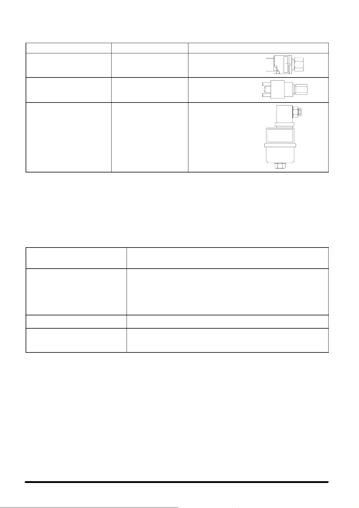
8 --- Eichungen
Das Klimagerät wurde bereits im Werk gemäß der u.g. Werte im Herstellerwert geeicht und geprüft.
BESTANDTEIL
Niederdruckwächter
(LP)
Hochdruckwächter
(HP)
Regler für
Ventilatorgeschwindigkeit
(BV)
STOP : 1 bar
START : 2 bar
(Feststehende Eichwerte)
STOP : 28 bar
START : 20 bar
(feststehende Eichwerte)
SET. : 18.8 bar
BAND P : 3.8 bar
(Für die Einstellung vergleiche
man die sich an Bord der
Maschine befindlichen Hinweise)
EICHUNGEN ANMERKUNGEN
automatische
Rückstellung
Manuelle
Rückstellung
durch Tastendruck
9 --- Wartung / Ersatzteile
Aus Sicherheitsgründen entferne man, wenn möglich, die Spannung vom Gerät durch Öffnen des QS1---Schalters bevor man irgendeine Wartung durchführt.
Das nachfolgende Wartungsprogramm sollte von einem Fachmann, vorzugsweise mit Wartungsvertrag, durchgeführt werden.
Wartungsprogramm --- Monatliche Kontrollen
Kontrollieren, ob der Ventilatormotor unbehindert und ohne unnormale Betriebs-
VENTILATOREN
LUFTFILTER
STROMKREIS
KÜ H L --- K R E I S L A U F
geräusche läuft. Sicherstellen, daß sich die Lager nicht aufheizen.
Stromaufnahme prüfen.
Den Filterzustand prüfen. Bei Bedarf reinigen oder ersetzen.
Für den Ersatz gehe man folgendermaßen vor:
S Die untere Tafel des Gerätes ausbauen.
S Den Befestigungsbügel entfernen und den Filter senkrecht aus dem Sitz nehmen.
S Ersatzfilter einführen
S Den Bügel erneut positionieren, den Bügel befestigen und die Tafel wieder
schließen.
In sehr staubigen Umgebungen muß die Kontrolle häufiger erfolgen.
S Die Stromversorgung an allen Polen prüfen.
S Sicherstellen, daß die Stromanschlüsse fest sind.
S Die Verdampfungsdruckwerte prüfen (durch einen Kältetechniker vorzunehmen).
S Die Stromaufnahme des Verdichters, dessen Kopftemperatur und das Vorhan-
densein evtl. anomaler Betriebsgeräusche prüfen.
S Sicherstellen, daß am Verdampfer keine Frostbildung vorliegt.
9.1 --- Entsorgung des Gerätes
Die Maschine wurde für einen kontinuierlichen Betrieb entworfen und gebaut. Die Lebensdauer einiger wichtigen Bestandteile wie Ventilat or und Verdichter, ist von der Wartung
abhängig, der sie unterstellt sind.
Die Entsorgung der Einheit muß durch einen spezialisierten
Kältefachmann erfolgen.
Die Kühlflüssigkeit und das Schmieröl, die in den Leitungen
enthalten sind, müssen gemäß der Bestimmungen des jeweiligen Landes aufgefangen und entsorgt werden.
9.2 --- Ersatzteile
Wir empfiehlen den Einsatz von originalen Ersatzteilen. Bei Anfragen jeweilsdie Artikelnummerund, sofern möglich, das Modell und die Serienummer des Teiles in der “Component List”
angeben.
9
Deutsch
Page 33

10 --- Anhang
10.1 --- Kontrolle des Gerätes nac h der Installierung
Es folgt ein Verzeichnis von durchzuführenden Kontrollen für den einwandfreien Zustand von Hisp nach der Installierung.
WICHTIG: JEDES GERÄT WIRD IN UNSEREN WERKEN VOR DER AUSLIEFERUNG GETESTET.
A) STATISCHE KONTROLLE
A . 1 ) S E --- V e r d a m p f e r
A.1.a) Man kontrolliere von Außen den einwan-
dfreien Zustand der Tafeln und der Befestigung; die Niete müssen in einwandfreiem Zustand sein.
A.1.b) Manprüfe,objedeMaschinemiteinemKon-
denswasserablaß mit einem Siphon ausgestattet ist, der über einen breiten Kurvenradius verfügt.
A.1.c) Man prüfe, daß die (Schlauch --- oder
Rohr---)Leitungen für die Ansaugung der
Freecooling--- Luft (Option) und das regenfeste Außengitter einschließlich metallischem
Vorfilter (Option) gegenwärtig und einwandfrei befestigt sind.
A.1.d) Man prüfe, daß der Überdruckschieber (Be-
wegbarkeit der Lamellen) gegenwärtig und
korrektbetreibbar ist, damitdie Freecooling--Luft (Option) problemlos ausgestoßen werden kann. Er muß vollständig mit äußerem
Regenschutzgitter ausgestattet sein.
A.1.e) Man prüfe, daß die Befestigung an der Decke
oder an der Gerätewand einwandfrei fest ist
und daß eventuelle durchgehende Befestigungen der Wand des zu belüftenden Raumes dicht sind.
A.1.f) Man erreiche die elektrische Schalttafel des
Raumes und schalte auf “OFF”.
A.1.g) Man entferne die unteren Kontrolltafelnfür die
Kontrolle, um zum Verdampfer zu gelangen.
A.1.h) Mangelange zur elektrischen Schalttafel und
schalte den Hauptschalter QS1 für die Netzversorgung auf “0”.
A.1.i) Man prüfe, daß im Schaltschrank keine
Fremdkörper liegen bleiben.
A.1.l) Man prüfe den korrekten Anschluß der Ver-
sorgungskabel und des Bus--- K a b e l s z w i -
schen Microface und entferntem Display.
A.1.m) Man prüfe die Befestigung und die Polaus-
richtung der Kabel für die Notversorgung
(Batterien) zum Inverter .Im ZweifelsfallschlagemanimelektrischenSchaltplannach.
WICHTIG: Man verändere keinesfalls die Einstellung der Potentiometer in der Inverterkarte.
A.1.n) Man prüfe die Befestigung der Kabel, der
elektronischen Bestandteile und der Schmelzsicherungen.
A.1.o) Man prüfe den Verdampferventilator, indem
man ihn von Hand verstellt: Er muß frei drehen und keinen unnormalen Lärm erzeugen.
Die Welle muß ausgerichtet sein.
A.1.p) Man prüfe die korrektePosition des Luftfilters.
A.1.q) Man prüfe den einwandfreien Zustand und
die Befestigung des Freecooling-- -Schiebers
(falls installiert).
A.1.r) Man prüfe die Ausrichtung der Förderlamel-
len aufgrund der eigenen Anforderungen.
A.1.s) Man prüfe die korrekte Positionierung der
Heizregister (Option) im Stromfluß, und achte
darauf, daß sie nicht mit den Wänden der Kli-
maanlage oder mit anderen Bestandteilen in
Kontakt gerät.
A.2) Angetriebenes Kondensatorgerät SC
A.2.a) Man entferne die Front--- und Seitentafeln,
um zum Kühlkreislauf Zugang zu haben (falls
die Umgebungsbedingungen dies erlauben:
manvermeidedenEintrittvonWasserindie
elektrische Schalttafel in das Kompressorgehäuse).
A.2.b) Man prüfe den einwandfreien Zustand des
Kühlkreises und versichere sich darüber, daß
den Leitungen entlang keine Ölflecken vorhanden sind.
A.2.c) Man prüfe den Kondensatorventilator, indem
man ihn mit einem Schraubenzieher verstellt:
Er muß frei drehen und keinen unnormalen
Lärm erzeugen.
A.2.d) Man prüfe, daß im Schaltschrank keine
Fremdkörper liegen bleiben. Der Verdampfer
muß korrekt angeschlossen sein und alle
elektrischen Anschlüsse müssen perfekt festgezogen sein.
Das Gerät ist für die dynamische Kontrolle bereit.
B) DYNAMISCHE KONTROLLE
B.1) Man schließe die Kontrollklappen des Ver-
dampfers, bis auf die Zugangsklappe zur
elektrischen Schalttafel, wieder.
B.2) Man prüfe die Erdung.
B.3) Man erreiche die elektrische Schalttafel des
Raumes und schalte auf “ON”.
B.4) Man gelange zur elektrischen Schalttafel und
schalte den Hauptschalter QS1 für die Netz-
versorgung auf “1”.
B.5) Man prüfe die Spannung auf den Hauptver-
sorgungstafeln.
B.6) Man prüfe die Spannung bei den Notversor-
gungskabeln.
B.7) Man stelle die durch das Kontrolldisplay Mi-
croface (der Hiromatic) gewünschte System-
darstellung ein, wie z.B. Set Point, Network
(über Zuschreibung einer Kennummer für je-
des Gerät), Parameterteilung, Stand---By,Dif-
ferentialwerte des Freecoolings (falls instal-
liert) usw.
B.8) Man lasse die Maschine laufen und messe
den durch den Verdampferventilator aufge-
nommenen Strom.
B.9) Man lasse den Kompressor starten (bei Be-
darf durch Forcieren des Systems über den
Regler) und warte ab, bis das System stabil
ist. Man messe den aufgenommenen Strom
bei laufendem Ventilator und Kompressor.
B.10) Man prüfe alle diese Werte und vergleiche sie
mit den OA (Operating Ampère), welche in
dieser Betriebsanleitung enthalten sind, um
unnormale elektrische Aufnahmewerte zu
vermeiden.
B.11) Man prüfe die Fördertemperaturmiteinem di-
gitalen Temperaturmesser.
B.12) Man prüfe die Überhitzung entsprechend der
Tabelle 10.
B.13) Man klemme die Hauptversorgung (von der
Haupttafel des Raumes) ab und prüfe, daß
der Inverter sich automatisch aktiviert.
B.14) Man stelle die korrekte Einstellung der Kon-
trollparameter wieder her.
B.15) Man schließe die Tafeln des Verdampfersund
des angetriebenen Kondensatorgerätes wie-
der.
Deutsch
10
Page 34

Page 35

Avertissements
Recommandations:
S conserver toujours la notice pendant toute la durée de vie de la machine;
S lire attentivement la notice avant toute intervention sur la machine;
S utiliser la machine uniquement pour l’emploi auquel elle est destinée; l’emploi impropre de la machine dégage le
fabricant de toute responsabilité.
La notice s’adresse à l’utilisateur final pour les seules opérations réalisables carters fermés.
En revanche, les opérations nécessitant l’ouverture de portes ou panneaux à l’aide d’outils doivent être effectuées uniquement par un personnel qualifié.
Chaque machine est munie de dispositif de sectionnement électrique qui permet à l’opérateur d’intervenir en conditions
de sécurité. Ce dispositif doit toujours être utilisé pour éliminer les dangers pendant l’entretien (décharges électriques,
brûlures, redémarrage automatique, parties en mouvement et commande à distance).
La clé de démontage des carters, fournie par nous, doit être gardée par le personnel préposé à l’entretien.
Pour l’identification de la machine (modèle et numéro de série), en cas de demande d’assistance ou de pièces détachées, lire la plaque d’identification apposée aussi bien à l’extérieur que à l’intérieur.
ATTENTION: cette notice peut être modifiée. L’utilisateur devra donc consulter la notice qui accompagne la machine pour avoir des
informations plus détaillées et mises à jour.
Index
1 -- Opérations préliminaires 1....................................................................
1.1 --- Préambule 1.....................................................................................
1. 2 --- Ins p e c ti o n 1.....................................................................................
1. 3 --- Tra n s p o r t 1......................................................................................
1.4 --- Imperméabilité du milieu 1.........................................................................
1.5 --- Limites de fonctionnement 1........................................................................
1. 6 --- Air e s d e s e r v i c e 1.................................................................................
2 -- Installation 1.................................................................................
2.1 --- Dimensions d’encombrement 1.....................................................................
2.2 --- Positionnement de l’unité ambiante 1................................................................
2.3 -- - Raccordements conduites de Freecooling (en option) 1................................................
2.4 --- Positionnement de l’unité de motocondensation 2.....................................................
2.5 -- - Raccordements frigorifiques 2......................................................................
2.6 -- - Raccordements hydrauliques 3.....................................................................
2.7 -- - Branchements électriques (voir Fig. 6, Fig. 7 et le schéma de câblage fourni avec l’unité) 3...................
2.8 --- Refroidissement d’urgence (en opt.) 3...............................................................
3-- Miseenmarche 3............................................................................
3.1 --- Circuit de réfrigération 3...........................................................................
3.2 --- Première mise en marche (ou après une longue interruption) 3..........................................
3.3 --- Mise en marche avec une basse température externe 4.................................................
3.4 --- Mise en marche et arrêt 4..........................................................................
4 -- Fonctionnement 4............................................................................
4. 1 --- Gé n é r a l i té s 4.....................................................................................
4.2 --- Refroidissement (voir Fig. 8) 4......................................................................
4. 3 --- Ch a u f f a g e (e n o p t i o n ) 4............................................................................
4.4 --- Refroidissement en modalité Freecooling (en option) 4.................................................
4.5--- Réglagedelavitesseduventilateur du condenseur 4..................................................
4.6 --- Refroidissement d’urgence (en option) 4.............................................................
5 -- Unités de commande à microprocesseur 4.....................................................
5.1 -- - Unité seul froid 5.................................................................................
5.2 -- - Unité froid et chaud 5.............................................................................
5.3 -- - Unité avec Freecooling 5...........................................................................
6 -- Charge de frigorigène R22 7..................................................................
6.1 -- - Caractéristiques du fluide frigorifique R22 7...........................................................
6.2 --- Charge de réfrigérant R22 7........................................................................
6. 3 --- Ch a r g e d ’ h u i l e 7..................................................................................
7 -- Charge de frigorigène R407C 7................................................................
7.1 --- Caractéristiques du fluide frigorifique R407C 7........................................................
7.2 --- Charge de réfrigérant R407C 7......................................................................
7. 3 --- Ch a r g e d ’ h u i l e 8..................................................................................
8-- Réglages 9..................................................................................
9 -- Entretien / Pièces détachées 9................................................................
9.1 -- - Démantèlement de l’unité 9........................................................................
9.2 -- - Pièces détachées 9...............................................................................
10 -- Appendice 10................................................................................
10.1 --- Contrôle de l’unité après l’installation 10.............................................................
Page 36

1 --- Opérations préliminaires
1 . 1 --- P r é a m b u l e
La notice suivante concerne l’installation, le fonctionnement et
l’entretien du Climatiseur d’air HISP, constitué par une unité
d’évaporation (SE, Split---Evaporante), positionnée à l’intérieur, et par une unité de condensation (SC, Split ---Condensante), positionnée à l’extérieur.
IMPORTANT :
Consulter aussi la notice de l’unité de commande Microface
fournie avec la machine (si l’option est installée) :
1 . 2 --- I n s p e c t i o n
Dès la réception de l’appareil, contrôler l’état général de celui--ci. En cas de constatation de domm ages, se plaindre auprès
de l’entreprise de transport.
1 . 3 --- Tr a n s p o r t
S Garder toujours l’unité de condensation en position verti-
cale et ne pas la laisser à l’extérieur.
S Pendant le transport, éviter de faire une pression sur les
arêtes supérieures de l’emballage.
S Déballer les unitésle plus près que possibledu lieu de l’ins-
tallation. Une fois déballées, éviter les chocs qui pourraient
se répercuter sur les composants internes.
1.4 --- Imperméabilité du milieu
Pourcréerdes conditions thermohygrométriquesstables dans
le milieu, procéder comme il suit :
S Créer une barrière à la vapeur pour les parois, le sol et le
plafond avec du matériel imperméable.
S S’assurer que la pièce est isolée de l’extérieur ; pour ce
faire, sceller les ouvertures, les entrées des câbles, etc.
1.5 --- Limite s de fonctionnement
Les unités sont prévues pour le fonctionnement dans les
champs de travail (voir Tab. 1). Ces limites s’entendent pour les
machines nouvelles, installées correctement ou maintenues
en bon état par un entretien correct.Les clauses de garantie ne
peuvent pas être appliquées à tout cas d’endommagementou
de mauvais fonctionnement éventuel pouvantse produire pendant ou suite à des opérations hors de la plage des valeurs
d’application.
1.6 --- Aires de service
L’unitédoit être dotée d’une aire de service appropriée comme
suit (voir Fig. 3 e Fig. 5).
Toutesles opérations d’entretien de l’unité d’évaporation peuvent être réalisées de la partie inférieure, par trois panneaux
amovibles pour avoir accès au tableau électrique, à la section
d’évaporation et de ventilation, ainsi qu’à la section de filtrage
et de Freecooling (si l’option est installée).
L’accès à l’unité de motocondensation est assuré par des panneaux amovibles fixés par des vis antivandalisme (l’outil prévu
à cet effet est fourni avec l’unité).
2 --- In s t a l l a t i o n
ATTENTION : l’unité ambiante ne doit jamais être installée à
l’extérieur.
2.1 --- Dimensions d’encombrement
Voir les Fig. 1 et Fig. 2 pour les dimensions d’encombrement
de l’unité d’évaporation (SE) et de l’unité externe de motocondensation (SC).
F i g . A --- U n i t é d ’ é v ap o r a t i o n S E
2.2 --- Positionnement de l’unité ambiante
S Déballer les unitésle plus près que possibledu lieu de l’ins-
tallation. Une fois déballées, éviter les chocs qui pourraient
se répercuter sur les composants internes.
S Le climatiseur d’air (unité ambiante) peut être installé dans
n’importe quel milieu fermé, pourvu qu’il ne s’agit pas d’un
local exposé à des conditions agressives.
S Positionner l’unité ambiante près de la source de chaleur
principale.
S Fixer l’unité au pla-
fond ou au mur en
utilisant 6 ( SE 05 ---
06) ou 8 (SE
08-- -10---13---14)
points de fixation à
expansion ou passants (dans ce cas, il
est nécessaire d’assurer l’étanchéité de
la fixation), en correspondance destrous φ 8 mm, situés sur les deux étriers
latéraux.
S S’assurer que le flux d’air circule librement.
S Pourpouvoir effectuer l’entretiende l’unité, il est nécessaire
de laisser l’Aire de Service en Fig. 5 libre d’entraves (Référence faite à la Fig. 5c, la distance minimale de 200 mm sur
la partie arrière de l’unité d’évaporation est approximative,
pour permettre le raccordement frigorifique avec l’unité de
motocondensation).
Fig. B --- Fig. B : détail de la fixation
2.3 --- Raccordements conduites de
Freecooling (en option)
Le climatiseur d’air peut être
fourni avec le dispositif de
Freecooling intégré (en option), qui utilise l’air frais externe pour baisser la température du local sans activer le
compresseur, par un rideau
de modulation motorisé,
pour fournir la puissance frigorifique exacte demandée.
Dans ce cas, l’unité est fournieaveclecôtéarrièreprévu
pour la reprise de l’air externe par les raccordements
possibles suivants :
S standard : double trou
de section circulaire,
pour tuyaux flexibles de
202 (SE 05 --- 06) ou 252
(S E 08 --- 1 0 --- 1 3 --- 1 4 )
mm de diamètre, à
fixer par des colliers
métalliques (en option).
S option : trou simple de
section rectangulaire, avec bride pour le tuyau rigide
560x190 mm (SE 05---06) ou 600x250 mm (SE
08---10---13 --- 14) (non fourni par nous) ;
Fig. C --- Conduites de Freecooling
1
Fra nçais
Page 37

Danslesdeuxcas,lestrouspercésdanslaparoidevrontêtre
protégés par des grilles antipluie prévues à cet effet et dotées
de préfiltre (en option), pour éviter l’entrée d’eau ou de corps
étrangers dans le climatiseur d’air.
Fig. D --- Grille externe antipluie avec préfiltre, qui
peut être inspectionnée
L’air externe, aspiré par le ventilateur et refoulé dans le local,
échappede ce dernier par un rideaude surpressioninstallésur
lesparoisdulocalmême(enoption);lerideauestprotégépar
une grille externe antipluie prévue à cet effet.
Fig. E --- Rideau de surpressioninterneavec ouverturedesailettesvers
l’extérieur et grille externe antipluie/antioiseaux correspondante
IMPORTANT : le rideau de Freecooling est bloqué par des vis,
pour éviter son endommagement pendant le transport. Les vis
doivent être retirées avant de mettre en marche le climatiseur
d’air (voir l’étiquette d’information correspondante sur la partie
arrièredel’unitéSE):
2.3.1 -- Installation sonde température extérieure
Installer la sonde de température de l’air extérieur située sur le
tableau électrique, à l’extrémité du conduit de canalisation.
IMPORTANT : le bulbe doit être positionné le plus à l’extérieur
possible, à l’abri des rayons du soleil et être protégé des intempéries (pluie, neige). La non --- observation de ces précautions
pourraient compromettre le bon fonctionnement de l’unité.
2.4 --- Positionnement de l’unité de
motocondensation
S L’unité de condensation doit être positionnée à l’extérieur,
pour permettre le refroidissement nécessaire (voir Fig. 3).
S Elle est raccordée au climatiseur d’air par les lignesfrigorifi-
ques. Utiliser des lignes frigorifiques le plus court que possible (ne pas utiliser des lignes de plus de 15 m équivalents
pour R22 et 10 m équivalents pour R407C).
S Pour permettre un passage d’air de capacité suffisante à
travers l’unité de condensation et pour utiliser l’espace
pour l’entretien éventuel, il est nécessaire de laisser l’Aire
de Service libre d’entraves, comme reporté en Fig. 5.
S Installer l’unité de condensation loin d’agents polluants (ex.
poudre, feuilles), pour garantir les meilleures performances de celle - --ci au fil des années.
S’il est possible de choisir entre plusieurs places, installer
de préférence l’unité de motocondensation à un endroit à
basse exposition aux rayons solaires afin d’optimiser les
performances de la machine. Veillerà ce qu’il y ait une circulationd’air adéquate. S’assurer qu’en cas de neige,l’unité ne risque pas d’être entièrement couverte. Ne pas
boucher les sections d’aspiration et d’évacuation de l’air.
Positionner l’unité de telle sorte que l’air chaud évacué et
le bruit ne dérangent pas les personnes.
Si l’unité de motocondensation est positionnée sur le toit
d’un bâtiment ou sur accrochée à des murs exposées à de
fortes rafales de vent, vérifier que l’unité est solidement fixée et, si nécessaire, utiliser des supports supplémentaires
ou bien des tirants pour la renforcer. La direction du vent
devra être perpendiculaire au sens d’évacuation de l’air.La
stabilité de la fixation devra être dûment assurée même en
cas de secousses telluriques.
S La Fig. 3 montre, par quelques exemples, comment install-
er l’unité de condensation.
En cas d’installation au mur,utiliser préférablement le kit de
fixation livré en option avec l’unité. Le kit contient, pour chaque unité de motocondensation : deux étagères en acier
galvanisé peintes à la poudre polyester de la couleur RAL
9002, finitions lisses ; supports antivibrations en élastomère ; tous les raccordements nécessaires en acier inox,
y compris les chevilles à expansion pour la fixation au mur
(voir Fig. 4).
NOTE : les chevilles à expansion contenues dans le kit sont
à utiliser uniquement en cas de fixation des étagères à des
mursenbétonouenbriques(ycomprislesbriques
trouées). Ne pas utiliser sur des parois à panneaux sandwich (p. ex. parois de conteneurs) ou sur des murs dont la
composition n’est pas connue. Dans ce type de situation,
il est préférable d’adopter le système de fixation le plus approprié pour la matière en cause.
Au contraire, en cas de non utilisationdukitoptionneldécrit
plus haut, avoir tout de même soin de prévoir des supports
antivibrations spéciaux à positionner entre l’unité de motocondensation et les étagères, de manière à éviter la propagation de vibrations. S’assurer en outre que les étagères
utilisées peuvent soutenir l’unité de motocondensation
dans des conditions de toute sécurité (p. ex. : prévoir des
situations temporaires de charges anomales sur l’unité).
2.5 --- Raccordements frigorifiques
CETTE OPERATION DOIT ETRE EXECUTEE PAR UN FRIGORISTE EXPERIMENTE.
L’unité de condensation et l’unité ambiante arrivent préchargées d’azote et doivent être chargées deréfrigérant (voir Chap.
6 --- Charge de réfrigérant R22 et Chap. 7 --- Charge de réfrigérant R407C).
a) Posedeslignes(Fig.9)
Raccorder le climatiseur d’air à l’unité de condensation en utili-
sant des lignes frigorifiques en cuivre cru ou recuit.
S Limiter le nombre de courbes imprimées ; en cas contraire,
chaque courbe devra avoir un rayon d’au moins 100 mm.
S La ligne du gaz doit être calorifugée.
S La ligne du liquide ne doit pas passer près de sources de
chaleur ; si cela n’est pas possible, la ligne devra être calorifugée.
S Si l’unité de condensation est positionnée plus haute que
l’unité d’évaporation, la dernière section du tuyau d’aspiration (tuyau calorifugé) doit être inclinée vers l’unité de condensation.
Par contre, si l’unité de condensation est positionnée plus
basse que le climatiseur d’air, il est conseillé de réaliser un siphon sur le tuyau d’aspiration.
Tab. A -- Diamètres standard des tuyaux pour R22
et R407C (*)
MODELE TUYAUDUGAZ TUYAUDULIQUIDE
HISP SE+SC05 φ 14 x1 φ 8x1
HISP SE+SC06 φ 16 x 1 φ 8 x1
HISP SE+SC08 φ 18 x 1 φ 10 x 1
HISP SE+SC10 φ 18 x 1 φ 12 x 1
HISP SE+SC13 φ 22 x 1 φ 12 x 1
HISP SE+SC14 φ 22 x 1 φ 12 x 1
(*) Valables pour des distances max. (équivalentes) jusqu’à 15 m
pour R22 et jusqu’à 10 m pour R407C.
b) Opération de vidange des lignes frigorifiques
L’opérationde vidange par la pompe prévue à cet effet (de qu-
alité) doit être effectuée en utilisant les raccords 1/4” SAE positionnés sur les robinets d’arrêt des unités.
Fra nçais
2
Page 38

2.6 --- Raccordements hydrauliques
Pendant le cycle de refroidissement, une partie de l’humidité
contenue dans l’air est condensée sur la batterie d’évaporation. L’eau de condensation est recueillie dans le réservoir au --dessous de la batterie et doit être déchargée à l’extérieur.
Ta b. B -- Raccordements hydrauliques (Fig. 10)
RACCORD DIMENSIONS
Evacuation de l’eau de condensation φ 21 mm
Pour l’évacuation de l’eau de condensation produite :
S utiliser des tuyaux en acier galvanisé, PVC ou en polythène
flexible.
S IMPORTANT : NE PAS RACCORDER ENTRE EUX LES
TUYAUX D’EVACUATION DE PLUSIEURS MACHINES.
S Assurer une inclinaison d’au moins 2% vers la sortie du tuy-
au d’évacuation.
S Vérifierla présence d’un siphon d’évacuation positionnéau
moins 30 mm sous le réservoir d’évacuation.
S Remplir d’eau le siphon d’évacuation en versant celle---ci
dans le réservoir de récolte de l’eau de condensation.
2.7 --- Branchements électriques (voir
Fig. 6, Fig. 7 et le sc héma de
câblage fourni avec l’unité)
1) Avant de procéder aux branchements électriques, s’assur-
er que :
S tous les composants électriques sont en conditions par-
faites ;
S toutes les vis terminales sont bien serrées ;
S la tension d’alimentation et la fréquence sont conformes
aux valeurs indiquées sur l’unité.
S l’interrupteur automatique QS1 est en position ouverte
(OFF)
S iln’yapasdecomposantssoustension.
2) Branchements des câbles d’alimentation :
S Unité d’évaporation : le climatiseurd’air est fourni avec un
tableau électrique et une plaque à bornes prévus pour le
fonctionnement par unité de commande à microprocesseur intégré Microface.
S Dans le tableau électrique, brancher le câble d’alimenta-
tionprincipal (non fourni par nous) sur l’interrupteurde sectionnement QS1 ou sur les bornes L1---N (pour la section
des câbles d’alimentation, voir Tab. 6) en passant par les
guide---câbles prévus à cet effet sur les côtés de l’unité.
scriptiondes alarmes, consulterle Chap. 5 et la notice de l’unité
de commande installée.
S Pourmettre en communication 2 ou plusieurs unités,instal-
lées dans le même local et dotées de l’unité de commande
MICROFACE avec interface HIROMATIC, utiliser le câble
HIROBUS (fourni) et le brancher comme indiqué dans le
schéma de câblage. Consulter, en outre, la notice Microface ou la notice Hiromatic pour la configuration des unités
en Etat d’attente.
S Unité de motocondensation:
IMPORTANT : L’UNITE DE MOTOCONDENSATION REÇOIT L’ALIMENTATION ELECTRIQUE DE L’UNITE D’EVAPORATION. (Consulter le schéma de câblage fourni
avec le climatiseur d’air).
Brancher le câble d’alimentation et le câble pour les
auxiliaires(pourlessectionscorrespondantesvoirFig.7et
Fig.7a) entre les plaques à bornes du climatiseur d’air et de
l’unité de condensation (câbles non fournis par nous).
3) L’unité d’évaporation SE standard a été conçue
pour être installée sur le plafond (Fig. G), mais
elle peut également être installée au mur avec
facilité. En ce cas, le contacteur KM3 du compresseur doit être tourné de 90o pour être décroché du
guidemétalliqueDIN(type”Omega”)surlequelilse
trouve et fixé au deuxième guide du mêmetype, dont l’unité est déja pourvue (Fig. H). De cette manière, l’axe du
contacteur restera en position horizontale. Sur l’unité SE,
pourvue de l’option DC Emergency Cooling, le contacteur
KM3 et le contacteur KM1 (ventilateurs en courant continu
de la section d’évaporation) doivent être tournés d’une
façon similaire et dans ce cas aussi, il faudra utiliser le
deuxième guide métallique de soutien, déjà prédisposé
sur l’unité.
F i g . G --- A s o f f i t t o
F i g . H --- A p a r e t e
Fig. F --- Détail des branchements électriques sur SE avec guide ---
S BrancherlecâbledecontrôleBusentrelacarteMicroface
S Brancherlecâbledemiseàlaterrejaune---vert.
En ce qui concerne les contacts d’alarme des différentes versions, ils sont disponiblessur plaque à bornesdans le tableau
électrique, avec la possibilité de les déplacer à distance, dans
la boîte à distance dotée d’afficheur de contrôle. Pour la de-
câble et gaine en plastique (non fournis par nous)
et l’afficheur à distance correspondant, en passant par les
guide---câbles prévus à cet effet sur les côtés et éventuellementsurlapartiearrièredel’unité.
2.8 --- Refroidissement d’urgence (en
opt.)
Le kit de refroidissement d’urgence est constitué de deux ventilateursradiaux à 24 ou à 48 V dc et d’un tableau électrique approprié. Amener l’alimentation à 48 ou 24 V dc dans le tableau
électrique,par un câble blindé de section minimale, comme indiqué dans le Tab. 7.
3 --- Mi s e en m a r c h e
3.1 --- Circuit de réfrigération
Voir Fig. 11 et Fig. 12.
3.2 --- Première mise en marche (ou après
une longue interruption)
Avantdemettreenmarcheleclimatiseur,ilestencoreconseillé
de vérifier que la tension et la fréquence d’alimentation sont
conformes aux valeurs indiquées sur la plaquette d’identification de l’unité.
Ensuite, il est possible de mettre en marche le climatiseur en
réglant l’interrupteur automatique QS1 sur ON.
Contrôler l’absorption électrique de tous les composants et la
3
Fra nçais
Page 39

comparer avec les données reportées dansles Tab. 3, Tab. 4 et
Tab. 5.
Vérifier qu’il n’y a pas d’alarmes actives, attendre que le
système arrive à régime et effectuer les contrôles suivants :
S vérifier que les ventilateurs fonctionnent correctement ;
S vérifier que la température est assurée et que le compres-
seur et les résistances de chauffage fonctionnent lorsque
nécessaire ;
S s’assurer que le régulateur de vitesse (Variex) du ventila-
teurde la section de condensationest calibré correctement
et qu’il contrôle le fonctionnement du ventilateur (voir
Chap. 4).
3.3 --- Mise en marche avec une basse
température externe
Encasdebassetempératureexterne(<0ûC), la mise en
marche de l’unité est facilitée par le retard d’activation de l’alarme de basse pression ; dans ce délai, les pressions dans le
circuit de réfrigération atteignent les valeurs normales de fonctionnement.
3.4 --- Mise en marche et arrêt
Les unitésdotées de l’unité de commande MICROFACE peuvent être allumées et éteintes en agissant sur l’interrupteur principal QS1 ; l’accès à ce dernier est possible par l’enlèvement
du panneau frontal inférieur. Pour mettre en marche et arrêter
l’unité, agir sur l’interrupteur de sectionnement QS1.
Pour les unités dotées d’interface HIROMATIC :
S mettre en marche l’unité en appuyant sur le bouton ON ---
OFF de l’Hiromatic (confirmé par SYS.ON sur l’afficheur)
;
S arrêter l’unité en appuyant sur le bouton ON --- OFF de l’Hi-
romatic (confirmé par SYS.OFF. visualisé sur l’afficheur).
N.B. : éteindre l’interrupteur principal QS1 uniquement si l’unité est arrêtée pendant une longue période.
4 --- Fonctionnement
4 . 3 --- C h a u f f a g e ( e n o p t i o n )
Le chauffage de l’air est réalisé par des résistances électriques
blindées, positionnées dans le flux d’air et actionnées d’après
la logique introduite dans l’unité de commande.
La remise à zéro manuelle du thermostat de sécurité, situé sur
les résistances, doit être effectuée par la grille de refoulement
d’air de l’unité d’évaporation.
4.4 --- Refroidissement en modalité
Freecooling (en option)
Lorsque la température de l’air externe est inférieure de quelques degrés à la températurede l’air interne,il est possibled’utiliser cette différence pour rafraîchir l’intérieur du local en admettant directement l’air externe, soit sans utiliser le compresseur. Ce qui permet d’obtenir une économiesensibled’énergie
électrique.
Lorsque les conditions prévues se réalisent, la servocommande, gérée par l’unité de commande Microface, ouvre le rideau mobile qui sépare lacirculationdes deux flux d’air interne
et externe. De cette manière, l’air externe, aspiré par le ventilateur, afflue dans le local et sortde celui---ci par un rideau de surpression installé sur les parois du local même (en option) et
protégé par une grille externe antipluie prévue à cet effet.
Le degré d’ouverture du rideau est déterminé sur la base de la
valeur du Point de Consigne qui doit être gardée ainsi que sur
celle de la température de l’air introduite (voir Chap. 5).
4.5--- Réglagedelavitesseduventilateur
du condenseur
Un capteur est positionné de façon à pouvoir relever constamment la pression de condensation du gaz réfrigérant. Sur la
base de cette information, un appareillage électronique (Va-
riex) règle la vitesse de rotation du ventilateur afin demaintenir
la pression de condensation dans les valeurs admises. De
cette manière, il est possible non seulement d’optimiser le
fonctionnement du compresseur, mais aussi d’obtenir une réduction sensible du niveau d’émission acoustique (surtout
pendant lesheures de la nuit), de faciliter la mise en marche du
compresseur aux basses températures ainsi que d’obtenirune
économie d’énergie électrique. En ce qui concerne le calibragedurégulateurdevitesse,voirleChap.8.
4 . 1 --- G é n é r a l i t é s
Le fonctionnement de l’unité est complètement automatique.
La séquence qui suit explique le fonctionnement de l’unité (voir
aussi Fig. 11 et Fig. 12 --- Circuit de réfrigération):
Le capteur de température,positionnépour l’aspiration dans le
local,fournit l’information concernantla condition del’air à traiter à l’unité de commande.
Cette dernière compare l’informationreçue avec les valeurs de
Point de Consigne (= température interne minimale désirée)
et de Différentiel programmées, en préparant le climatiseur
pour le traitement de l’air conformément aux modalités suivantes :
4 . 2 --- R e f r o i d i s s e m e n t (voir Fig. 8)
Le compresseur et les ventilateurs se mettent en marche lorsque la températuredu milieu à climatiser dépasse la valeur établie. L’airaspiré par le ventilateur centrifuge entre dans l’unité à
travers la grille arrière (la grille inférieure pour les unités avec
l’option Freecooling), passe immédiatement à travers le filtre et
puis parl’évaporateur. Le frigorigènefroid coule à travers l’évaporateur et refroidit ainsi l’air qui lui passe à travers. L’air traité
est refoulé dans le milieu climatisé à travers l’ouverture de refoulement. La chaleur soustraite du milieu et celle produite par
le fonctionnementdes moteurs du climatiseursont éliminées à
travers le condensateur, situé dans l’unité de motocondensation et traversé, grâce au ventilateur,par l’air externe. La vitesse
du ventilateur est variée continuellement (Variex, voir par. 4.5)
en fonction de la pression de condensation. Pour la logique de
fonctionnement de l’unité de commande, voir le Chap. 5.
4.6 --- Refroidissement d’urgence
(en option)
Cette option est disponible pour toutes les applications pour
lesquelles il est important de garantir la circulation de l’air dans
le local, même en cas d’interruption de l’alimentation électrique du réseau. Dans ce cas, les unités peuvent être alimentées
avec les batteries d’urgence à 48 V dc (ou 24 V dc).
La modalité d’intervention du système d’urgence dépend de
l’état de l’interrupteur automatique QS1 :
S QS1 = ON En cas d’absences d’interruption de l’alimenta-
tion principale, le système d’urgence reste inactif ; si la tension sur la ligne d’alimentation principale est coupée, l’énergie est prélevée automatiquement des batteries d’urgence à 48 V dc (ou 24 V dc) et les ventilateurs de la section
d’évaporation ainsi que l’unitéde commande électronique
sont alimentés. De cette manière, toutes les fonctions de
l’unité continuent d’être gérées, tout en permettant la recirculation de l’air interne (ou l’afflux d’air externe, si l’unité est
dotée du système Freecooling) au cas où la température
dans le local dépasserait les limites autorisées.
5 --- Unités de commande à
microprocesseur
La machine est disponible dans quatreconfigurations de fonctionnement différentes :
1) unité seul froid ;
2) unité froid et chaud ;
3) unité avec Freecooling, seul froid ;
Fra nçais
4
Page 40

4) unité avec Freecooling, froid et chaud.
Dans toutes les versions, l’afficheur de contrôle est positionné
à distance sur une une boîte métallique à installer dans lelocal.
5.1 --- Unité seul froid
5.1.1 -- Logique de contrôle
Cette option, gérée par le dispositif de contrôle à microprocesseur Microface, est éventuellement associée au dispositif de
contrôle Hiromatic, pour le monitoring complet de tous les paramètres de fonctionnement de l’unité (voir la notice en annexe). L’algorithme de contrôle appuie sur un type de réglage
à 1 échelon, pour le refroidissement avec le compresseur : le
dispositifde contrôlegère tousles retards d’activationdu compresseur,pour en garantir le bon fonctionnementet en optimiser la durée de fonctionnement.
Bande P
Unité seul
froid
Réglage Refroidissement
Fig. I --- Fonctionnement unité seul froid.
5.1.2 -- Marche-- arrêt
Il y a deux procédures de mise en marche ou d’arrêt de l’unité :
a) par l’entrée digitale de la carte Microface;
b) par le bouton ON --- OFF sur l’interface Hiromatic (en op-
tion).
Priorité avec Hiromatic : a) et b) doivent être considérés comme 2 contacts en série ; l’unité ne peut travailler que si l’option
ON est sélectionnée pour tous les contacts.
5.1.3 -- Gestion des alarmes
Les 2 contacts d’alarme disponibles sur la plaque à bornes du
panneau de contrôle sont utilisés comme il suit :
1) Alarme générale :
S basse pression du compresseur
S haute pression du compresseur (remise à zéro sur le pres-
sostat)
S capteur en panne
S mémoire en panne
S ventilateur en panne
2) Avertissement général --- signalisation de plusieurs condi-
tions irrégulières, parmi lesquelles :
S température élevée
S température réduite
Notes :
S l’Alarme et l’Avertissement doivent être remis à zéro man-
uellement sur la Microface.
S Le déclenchement d’une alarme provoque l’arrêt de l’unité
et fait intervenir l’unité en Etat d’attente (si présente).
S L’avertissement n’arrête pas l’unité.
5.1.4 -- Carte des alarmes en option
Outre à ce qui est prévu dans la configurationstandard, la carte
des alarmes en option est dotée de contacts de relais pour
avoir les alarmes suivantes séparées :
1) Haute pression et basse pression du compresseur
2) Température élevée
3) Température réduite
4) Alarme filtre sale (si installée)
5) Panne du ventilateur
Le déclenchement de ces alarmes provoque l’arrêt de l’unité
conformément aux modalités reportées dans le paragraphe
précédent.
Pour la description complète des alarmes, consulter la notice
M i c r o f a c e c i --- j o i n t e .
°C
5.1.5 -- Unité en Etant d’attente
Les unités en Etat d’attente sont gérées de façon complètement automatique, grâce à la possibilité de brancher le dispositifdecontrôleMicroface.Lamiseenmarched’uneunitéen
Etat d’attente se produit en cas de déclenchement d’une
alarme qui bloque l’unité principale ; ce qui s’avère même sil’unité principale est éteinte ou si elle disparaît du système à
cause d’une panne du bus de connexion des unités de commande.
La rotation horaire des unités en Etat d’attente est automatique
et elle intervient toutes les 24 heures ; ce qui permet l’usure homogène des composants du système.
Si le système est branché sur l’interface Hiromatic, il est possible d’introduire une gestion de la rotation différente.
Si plusieurs unités fonctionnent simultanément avec le même
Point de Consigne, la température utilisée pour le contrôle correspond à la moyenne des températures mesurées. En outre,
dans le fonctionnementavec le compresseur, la bande proportionnelle est répartie dans un nombre de parties deux fois le
nombre d’unités faisant partie du système ; ce qui permet de
partager la puissance frigorifique totale disponible.
5.2 --- Unité froid et chaud
5.2.1 -- Logique de contrôle
L’algorithme de contrôle se base sur un type de réglage à 1
échelon,pour le chauffage et le refroidissement avec compresseur.
L’unité de commande gère tous les retards d’activation du
compresseur ,comme il résulte du cas précédent, pourgarantir
le fonctionnementcorrectde celui---ci et pour prolonger sa durée opérationnelle.
Plage neutre!P@ Bande P !P@ Bande P
Unité froid
et chaud
Chauffage
Fig. J --- Fonctionnement unité froid + chaud.
Réglage Refroidissement
°C
5.2.2 -- Marche-- arrêt
Voir le par. 5.1.2.
5.2.3 -- Gestion des alarmes
Voir le par. 5.1.3.
Un signal d’avertissement général supplémentaire signale la
condition d’anomalie suivante :
S thermostat de résistance (remise à zéro sur le thermostat)
Notes :
S l’avertissement n’arrête pas l’unité.
S En cas d’intervention du thermostat de sécurité résis-
tances, la remise à zéro doit être effectuée sur le thermostat
suivant les modalités indiquées ci---dessus.
5.2.4 -- Carte des alarmes en option
Voir le par. 5.1.4.
5.2.5 -- Unité en Etant d’attente
Voir le par. 5.1.5.
5.3 --- Unité avec Freecooling
5.3.1 -- Logique de contrôle
Cette option est également gérée par l’unité de commande à
microprocesseur Microface, éventuellement combinée à l’unité de commande Hiromatic, pour le monitoring complet de
tous les paramètres de fonctionnement de l’unité (voir notice
en annexe). L’algorithme de contrôle se base sur un réglage à
1 échelon, pour le chauffage et le refroidissement avec compresseur, et sur un réglage de type proportionnel---complémentaire, pour le refroidissement en modalité Freecooling,
5
Fra nçais
Page 41

avec l’introduction du Point de Consigneet de la bande proportionnelle (P) (Fig. K).
L’unité de commande gère tous les retards d’activation du
compresseur, comme dans les 2 cas précédents, afin d’assurer le fonctionnement correct de celui---ci et de prolonger autant
que possible sa durée opérationnelle.
L’activation de la modalité Freecooling se produit sur la base
de la différence (qui peut être réglée) entre la température interne et celle externe. Ce qui signifie que, au cas où la différence entre les 2 températures dépasserait une certaine valeur,
l’unité passe automatiquement au mode Freecooling: le compresseur est mis hors service et la sortie analogique contrôlele
servomoteur à 3 points du rideau. Le degré d’ouverture du rideau est déterminé en fonction de la différence detempérature
entre l’extérieur et l’intérieur ainsi qu’en fonction de la température de l’air introduit dans le milieu, qui ne peut pas descendre
au---dessous d’une valeur de sécurité établie.
Plage neutre!P@ Bande P !P@ Bande P
Chauffage °C
Chauffage
Fig. K --- Fonctionnement du compresseur, résistances électriques
et ouverture du rideau de Freecooling
Réglage
Plage neutre!P@ Bande P !P@ Bande P
Réglage
Refroidissement
Refroidissement
modalité
Freecooling
Modalité de refroidissement
avec compresseur
°C
Si la température interne dépasse la bande proportionnelle de
plus de 20 % pendant plus de 10 minutes, l’unité passe au refroidissement avec compresseur et la modalité Freecoolingest
invalidée pendant
1
/2heure. Au cas où la température interne
dépasseraitla bande proportionnelle de plus de 50 % pendant
plus de 2 minutes, la modalité Freecooling est invalidée pen-
1
dant
/2heure et l’unité passe au refroidissement par compres-
seur frigorifique.
5.3.2 -- Marche-- arrêt
Il y a deux procédures de mise en marche ou d’arrêt de l’unité :
a) par l’entrée digitale de la carte Microface;
b) par le bouton ON ---OFF sur l’interface Hiromatic (en op-
tion).
Priorité avec Hiromatic : a) et b) doivent être considérés comme 2 contactsen série; l’unité ne peut travailler que si pourtous
lescontactsl’optionONestsélectionnée.
5.3.3 -- Gestion des alarmes
Les 2 contacts d’alarme disponibles sur la plaque à bornes du
panneau de contrôle sont utilisés comme il suit :
1) Alarme générale :
S basse pression du compresseur
S haute pression du compresseur (remise à zéro sur le pres-
sostat)
S capteur en panne
S mémoire en panne
S ventilateur en panne
2) Avertissement général --- signalisation de plusieurs condi-
tions irrégulières, parmi lesquelles :
S température élevée
S température réduite
S thermostat résistance (remise à zéro sur le thermostat)
Notes :
S l’Alarme et l’Avertissement doivent être remis à zéro man-
uellement sur la Microface.
S Le déclenchement d’une alarme provoque l’arrêt de l’unité
et fait intervenir l’unité en Etat d’attente (si présente). Au
cas où l’unité serait en Etat indépendant, les alarmes de
haute et basse pression n’arrêtent pas la machine afin de
permettre, le cas échéant, le fonctionnement en mode
Freecooling.
S L’avertissement n’arrête pas l’unité.
S En cas d’intervention du thermostat de sécurité résis-
tances, la remise à zéro doit être effectuée sur le thermostat
suivant les modalités indiquées ci---dessus.
5.3.4 -- Carte des alarmes en option
Outre à ce qui est prévu par la configuration standard, la carte
des alarmes, qui peut être fournie en option, est dotée de contacts de relais pour avoir les alarmes suivantes séparées :
1) Haute pression et basse pression du compresseur
2) Température élevée
3) Température réduite
4) Alarme filtre sale (si installé)
5) Panne du ventilateur
Ces alarmes engendrent l’arrêt de l’unité de la même façon il-
lustrée au paragraphe précédent.
Pourla descriptioncomplète des alarmes, voir la noticeMicro-
face ci--- jointe.
5.3.5 -- Unité en Etant d’attente
Les unités en Etat d’attente sont gérées de façon complètement automatique, grâce à la possibilité de brancher le dispositifdecontrôleMicroface.Lamiseenmarched’uneunitéen
Etat d’attente se produit en cas de déclenchement d’une
alarme qui bloque l’unité principale ; ce qui s’avère même sil’unité principale est éteinte ou si elle disparaît du système à
cause d’une panne du bus de connexion des unités de commande.
La rotation horaire des unités en Etat d’attente est automatique
et elle intervient toutes les 24 heures ; ce qui permet l’usure homogène des composants du système.
Si le système est branché sur l’interface Hiromatic, il est possible d’introduire une gestion de la rotation différente.
Si plusieurs unités fonctionnent simultanément avec le même
Point de Consigne, la température utilisée pour le contrôle correspond à la moyenne des températures mesurées. En outre,
dans le fonctionnementavec le compresseur, la bande proportionnelle est répartie dans un nombre de parties deux fois le
nombre d’unités faisant partie du système ; ce qui permet de
partager la puissance frigorifique totale disponible.
Le fonctionnement en modalité Freecooling est homogène et
simultané sur toutes les unités.
La Fig. L, reportée comme exemple, représente le fonctionnement d’un système constitué de 3 unités.
!P@ Bande P !P@ Bande P
3
2
Chauffage
223
3
1 = unité principale
2 = unité en Etat d’attente
3 = unité en Etat d’attente
Fig. L --- Système constitué de 3 unités tot ales, dont 2 en Etat
Chauffage
d’attente---UnitédecommandeMicroface
mode Freecooling
Plage neutre
1
Réglage
Modalité de refroidissement du
compresseur
Plage neutre!P@ Bande P !P@ Bande P
11
Réglage
Refroidissement
Refroidissement
°C
°C
Fra nçais
6
Page 42

6 --- Charge de frigorigène
R22
IMPORTANT: CES OPERATIONS DOIVENT ETRE EXECUTEES PAR UN FRIGORISTE EXPERT.
L’UNITEESTFOURNIEPRECHARGEED’AZOTE.
6.1 --- Caractéristiques du fluide
frigorifique R22
A une température et une pression normales, il est un gaz incolore qui présente une basse toxicité, est ininflammable et a une
valeur limite d’exposition admise (AEL/TLV) égale à 1000 ppm
(valeur moyenne considérée sur 8 heures par jour).
En cas de fuites, aérer le local avant d’y séjourner.
6.2 --- Charge de réfrigérant R22
EN CAS DEREPARATIONDU CIRCUIT DE REFRIGERATION,
RECUPERER TOUT LE REFRIGERANT DANS UN CONTENEUR : NE PAS LE DISPERSER DANS L’ENVIRONNEMENT.
1) Une fois que les lignes frigorifiques sont raccordées aux
voies principales des robinets positionnés sur l’unité d’évaporation et sur celle de motocondensation, décharger
l’azote préchargé en agissant sur la voie ¼” SAE prévue à
cet effet, complète de vanne pointeau, de l’unité de motocondensation.
2) Effectuer la vidange du circuit grâce à la pompe spéciale
du vide, créant un vide de 0,7 mbars absolus.
3) 3 heures plustard contrôlerle niveau, il ne doit pas dépass-
er 1,3 mbars absolus. Si le vide n’est pas maintenu, cela
veut direqu’il y aurait desfuites. Réparer le circuit et répéter
les opérations à partir du point 2.
4) Raccorder le cylindre de remplissage à la ligne du liquide
de l’unité de motocondensation et commencer à charger
la quantité de réfrigérant R22 reportée dans le Tab. C.
Tab. C -- Charge de réfrigérant R22 pour une dis-
tance de 5 m entre l’unité d’évaporation
et l’unité de motocondensation.
MODELE Charge de réfrigérant R22 [kg]
Hisp SE+SC05 2.2
Hisp SE+SC06 2.5
Hisp SE+SC08 4.3
Hisp SE+SC10 4.4
Hisp SE+SC13 4.4
Hisp SE+SC14 4.4
5) Dans l’impossibilitéde compléter le remplissage,déplacer
le cylindre de façon qu’il aspire avec le compresseur et
compléter le remplissage ou, en tout cas, une fois terminé
le remplissage, procéder comme il suit :
6) faire démarrer l’unité comme décrit au par. 3.2.
7) Actionner manuellement le compresseur.
8) Garantir une température de condensation constante (de
préférence 50°C) ; si nécessaire, boucher partiellement la
surface d’échange du condenseur pour obtenir ces conditions.
9) Attendre que les conditions de fonctionnement de tout le
circuit de réfrigération reviennent à la normalité.
10) Vérifier à régime que les valeurs de surchauffage corre-
spondent à celles qui sont reportées dans le Tab. D suivant
(dans celui - --ci sont indiquées les températures manométriques)
Tab. D -- Tableau des surchauffages R22
Température interne °C 24 27
Humidité interne %HR 50 50
Surchauffage compresseur °C 8 12
Valeurs correspondantes à T de condensation = 50°C
Pourdesdistancesdelalignefrigorifiquedeplusde5metde
moins de 15 m, il faut augmenter la charge introduite dans le
circuit, comme reporté dans le Tab. E suivant :
Tab. E -- Charge additionnelle de réfrigérant R22
pour un mètre de distance additionnelle
(plus de 5 m, jusqu’à max. 15 m)
Diamètretuyauduliquide
8 mm (partie externe du tuyau) 30
10 mm (partie externe du tuyau) 53
12 mm (partie externe du tuyau) 70
Valeurs correspondantes à T de condensation = 50°C
NOTE : par distance l’on entend la longueur de tuyauterie, y
compris les courbes, entre l’unité interne et celle externe, pour
la ligne du liquide uniquement (ne pas additionner aller + retour).
Charge de réfrigé-
rant R22 [g/m]
6.3 --- Charge d’huile
L’huile à utiliser pour la remise à niveau est SUNISO 3GS; à
défaut de ce type d’huile, utiliser une huile ayant les mêmes
caractéristiques (voir Tab. F)
NE JAMAIS MELANGER D’HUILES NON COMPATIBLES.
VIDERETNETTOYERLATUYAUTERIEAVANTDE
REMPLACERLETYPED’HUILEUTILISE
Tab. F -- Huile Suniso 3GS (standard)
poids spécifique approximatif (à 15 _C)
point d’inflammation (C.O.C.)
point d’écoulement
viscosité ENGLER à 50 _C
index de viscosité
corrosion sur cuivre (100 _C, 3 heures) ASTM D130
valeur de neutralisation
résidu carbonique conradson
rigidité diélectrique
:
0,91 kg/l
:
170 _C
:
--- 4 0 _C
:
2,7 E
:
0
:
1
:
0,03 max.
:
0%
:
> 30kV
7 --- Charge de frigorigène
R407C
IMPORTANT : CES OPERATIONS DOIVENT ETRE EXECUTEES PAR UN FRIGORISTE EXPERT.
L’UNITEESTFOURNIEPRECHARGEED’AZOTE.
7.1 --- Caractéristiques du fluide
frigorifique R407C
A une température et une pression normales, il est un gaz incolore qui présente une basse toxicité, est ininflammable et a une
valeur limite d’exposition admise (AEL/TLV) égale à 1000 ppm
(valeur moyenne considérée sur 8 heures par jour).
En cas de fuites, aérer le local avant d’y séjourner.
7.2 --- Charge de réfrigérant R407C
EN CAS DE REPARATION DU CIRCUIT DE REFRIGERATION, RECUPERER TOUT LE REFRIGERANT DANS UN
CONTENEUR : NE PAS LE DISPERSER DANS L’ENVIRONNEMENT.
1) Une fois que les lignes frigorifiques sont raccordées aux
voies principales des robinets positionnés sur l’unité d’évaporation et sur celle de motocondensation, décharger
l’azote préchargé en agissant sur la voie ¼” SAE prévue à
cet effet, complète de vanne pointeau, de l’unité de motocondensation.
2) Effectuer la vidange du circuit grâce à la pompe spéciale
du vide, créant un vide de 0,3 mbars absolus.
3) 3 heures plustard contrôlerle niveau, il ne doit pas dépass-
er 1,3 mbars absolus. Si le vide n’est pas maintenu, cela
veut direqu’il y aurait desfuites. Réparer le circuit et répéter
les opérations à partir du point 2..
7
Fra nçais
Page 43

4) Raccorder le cylindre de remplissage à la ligne du liquide
de l’unité de motocondensation et commencer à charger
la quantité de réfrigérant R407C reportée dans le Tab. G .
Tab. G -- Charge de réfrigérant R407C pour une
distance de 5 m entre l’unité d’évaporation et l’unité de motocondensation.
MODELE Charge de réfrigérant R407C
[kg]
Hisp SE+SC05 2.2
Hisp SE+SC06 2.5
Hisp SE+SC08 4.3
Hisp SE+SC10 4.4
Hisp SE+SC13 4.4
Hisp SE+SC14 4.4
5) Dans l’impossibilitéde compléter le remplissage,déplacer
le cylindre de façon qu’il aspire avec le compresseur et
compléter le remplissage ou, en tout cas, une fois terminé
le remplissage, procéder comme il suit :
6) faire démarrer l’unité comme décrit au par. 3.2.
7) Actionner manuellement le compresseur.
8) Garantir une température de condensation constante (de
préférence 50°C) ; si nécessaire, boucher partiellement la
surface d’échange du condenseur pour obtenir ces conditions.
9) Attendre que les conditions de fonctionnement de tout le
circuit de réfrigération reviennent à la normalité.
10) Vérifier à régime que les valeurs de surchauffage correspondent à celles qui sont reportées dans le Tab. H suivant
(dans celui - --ci sont indiquées les températures manométriques)
7 . 3 --- C h a r g e d ’ h u i l e
L’huile à utiliser pour la remise à niveau est MOBIL EAL ARC--TIC 22CC; à défaut de ce type d’huile, utiliser une huile ayant
les mêmes caractéristiques (voir Tab. J)
NE JAMAIS MELANGER D’HUILES NON COMPATIBLES.
VIDERETNETTOYERLATUYAUTERIEAVANTDE
REMPLACERLETYPED’HUILEUTILISE
Tab. J -- Huile Mobil Eal Arctic 22CC (standard)
poids spécifique approximatif (à 15 _C)
point d’inflammation (C.O.C.)
point d’écoulement
index de viscosité
viscosité 40_C
viscosité 100_C
Bien entendu, les robinets du compresseur doivent être ouverts seulement après que tout le système a été mis sous vide et
partiellement chargé.
:
0,99 kg/l
:
245 _C
:
< --- 5 4 _C
:
116
:
23.6 cST
:
4.7 cST
Tab. H -- Tableau des surchauffages R407C
Température interne °C 24 27
Humidité interne %HR 50 50
Surchauffage compresseur °C 8 12
Valeurs correspondantes à T de condensation = 50°C
Pourdesdistancesdelalignefrigorifiquedeplusde5metde
moins de 10 m, il faut augmenter la charge introduite dans le
circuit, comme reporté dans le Tab. I suivant :
Tab. I -- Charge additionnelle de réfrigérant
R407C pour un mètre de distance additionnelle (plusde 5 m, jusqu’àmax. 10 m)
Diamètretuyauduliquide
8 mm (partie externe du tuyau) 30
10 mm (partie externe du tuyau) 53
12 mm (partie externe du tuyau) 70
Valeurs correspondantes à T de condensation = 50°C
NOTE : par distance l’on entend la longueur de tuyauterie, y
compris les courbes, entre l’unité interne et celle externe, pour
la ligne du liquide uniquement (ne pas additionner aller + retour).
Charge de réfrigé-
rant R407C [g/m]
Fra nçais
8
Page 44

8 --- Ré g l a g e s
Le climatiseur d’air a déjà été essayé et calibré en usine, comme indiqué ci ---dessous.
COMPOSANT
Pressostat de basse pression
(LP)
Pressostat de haute pression
(HP)
Régulateur de vitesse
ventilateur
(BV)
ARRET : 1 bar
DEMARRAGE : 2 bar
(calibrages fixes)
ARRET : 28 bar
DEMARRAGE : 20 bar
(calibrages fixes)
REGLAGE : 18.8 bar
BANDE P : 3,8 bar
(Pour le réglage, voir les instructions jointes à bord machine)
CALIBRAGES NOTES
réarmement
automatique
réarmement
manuel
si l’on appuie sur le bouton
9 --- Entretien / Pièces détachées
Pour des raisons de sécurité, couper la tension à l’unité si possible ; pour ce faire, ouvrir l’interrupteur QS1 avant d’effectuer toute
opération d’entretien.
Le Programme d’Entretien indiqué ci---après devrait être exécuté par un technicien spécialisé, qui intervient de préférence avec un
contrat d’entretien.
Programme d’entretien --- Contrôle mensuel
Contrôler que le moteur du ventilateur tourne librement et sans produire des bruits
VENTILATEURS
FILTRES A AIR
CIRCUIT ELECTRIQUE
CIRCUIT DE REFRIGERATION
anomales ; s’assurer que les roulements ne se chauffent pas.
Contrôler l’absorption de courant aussi.
Contrôler l’état du filtre ; le nettoyer ou le remplacer si nécessaire.
Pour le remplacement :
S enlever le panneau inférieur de l’unité
S enlever l’étrier de fixation et extraire verticalement le filtre de son logement
S introduire la pièce de rechange
S repositionner et fixer l’étrier et fermer à nouveau le panneau
Dans des milieux très poussiéreux, exécuter ce contrôle plus fréquemment.
S Contrôler l’alimentation électrique dans toutes les phases.
S S’assurer que les connexions électriques sont bien serrées.
S Contrôler les pressions d’évaporation (faire exécuter cette opération par un frigo-
riste expert).
S Contrôler l’absorption de courant du compresseur, la température en tête et la
présence d’éventuels bruits anomales.
S S’assurer que la glace ne se forme pas sur l’évaporateur.
9.1 --- Démantèlement de l’unité
Lamachineaétéconçueetconstruitepourgarantirunfonctionnement continu. La durée de certains composants principaux, tels que le ventilateur et le compresseur, dépend des
soins d’entretien qu’ils ont reçus.
En cas de démantèlement de l’unité, l’opération devra être effectuée par un personnel frigoriste spécialisé.
Le fluide frigorigène et l’huile de lubrification contenus dans le
circuit devront être récupérés en conformité avec les normes
en vigueur dans votre Pays.
9.2 --- Pièces détachées
On recommande l’utilisation de pièces détachées originales.
En cas de demande, faire référence à la “Component List”,
jointe à la machine, et spécifier le modèle et le numéro de série
de l’unité.
9
Fra nçais
Page 45

10 ---Appendice
10.1 --- Contrôle de l’unité après l’installation
Nous indiquons ci---après une liste des contrôles à effectuer pour vérifier l’intégrité de Hisp après l’installation.
IMPORTANT : CHAQUE UNITE EST TESTEE DANS NOS ATELIERS AVANT LA LIVRAISON.
A) CONTROLE STATIQUE
A.1) Unité d’évaporation SE
A.1.a) Contrôler visuellement l’intégrité des pan-
neaux et de leur fixation ; intégrité des rivets.
A.1.b) Vérifier la présence d’un tuyau d’évacuation
de l’eau de condensation pour chaque machine, complet de siphon à ample rayon de
courbure ;
A.1.c) Vérifier la présence et la fixation des conduits
(rigides ou flexibles) d’aspiration d’air Freecooling (en option) et de la grille externe antipluiecomplètedepréfiltremétallique(opt.);
A.1.d) Vérifier la présence et le bon fonctionnement
(mobilité des ailettes) du rideau de surpression pour l’évacuation de l’air de Freecooling
(opt.), complet de grille externe antipluie.
A.1.e) Vérifier la fixation de l’unité au plafond ou au
mur et l’étanchéité des éventuelles fixations
qui passent à travers les parois du local à climatiser ;
A.1.f) Accéder au tableau électrique du local et le
positionner sur “OFF”.
A.1.g) Enlever les panneaux d’inspection inférieurs
pour avoir accès à l’intérieur de l’unité d’évaporation.
A.1.h) Accéder au tableau électrique et positionner
sur “0” l’interrupteur principal QS1 d’alimentation de réseau.
A.1.i) Vérifier l’absence de corps étrangers dans le
tableau électrique.
A.1.l) Vérifier la connexion correcte des câbles d’ali-
mentationetducâbleBus entre la Microface
et l’afficheur à distance.
A.1.m) Vérifier la fixation et la polarité des câbles pour
l’alimentation d’urgence (batteries) à l’inverseur. En cas de doutes, consulter le schéma
électrique. IMPORTANT : ne pas altérer le
réglage des potentiomètres dans la carte inverseur.
A.1.n) érifier la fixation de câbles, composants élec-
troniques et fusibles.
A.1.o) ontrôler le ventilateurd’évaporation en le tour-
nant manuellement : il doit tourner librement,
sans faire de bruit anomale. L’arbre doit être
aligné.
A.1.p) Vérifier la position correcte du filtre à air.
A.1.q) Vérifier l’intégrité et la fixation du rideau de
Freecooling (si l’option est installée)
A.1.r) Vérifier l’orientation des ailettes de refoule-
ment en fonction de ses exigences.
A.1.s) Vérifier le positionnement correct des rési-
stances électriques de chauffage (en option)
dans le flux d’air : contrôler qu’elles ne soient
pasencontactaveclesparoisduclimatiseur
ou avec d’autres composants.
A.2) Unité de motocondensation SC
A.2.a) Enlever les panneaux frontal et latéral pour
avoir accès au circuit de réfrigération lorsque
les conditions atmosphériques le permettent.
Eviter l’entrée d’eau dans le tableau électrique et dans le logement du compresseur.
A.2.b) Vérifier l’intégrité du circuit de réfrigération, en
s’assurant de l’absence de tâches d’huile
dans le logement du compresseur et le long
des tuyauteries.
A.2.c) Contrôlerle ventilateur de condensation en le
tournant par un tournevis : il doit tournerlibrement, sans faire de bruit anomale.
A.2.d) Vérifier l’absence de corps étrangers dans le
tableau électrique, la connexion correcte à
l’unité d’évaporation et le serrage de toutes
lesconnexionsélectriques.
L’unité est prête pour le contrôle dynamique.
B) CONTROLE DYNAMIQUE
B.1) Fermer à nouveau les panneaux d’inspection
de l’unité d’évaporation, à l’exception du pan-
neau d’accès au tableau électrique.
B.2) Vérifier la connexion à la terre.
B.3) Accéder au tableau électrique du local et le
positionner sur “ON”.
B.4) Accéder au tableau électrique de l’unité
d’évaporationet positionnersur “1” l’interrup-
teur principal QS1 d’alimentation de réseau.
B.5) Vérifier la tension des câbles d’alimentation
principale.
B.6) Vérifier la tension des câbles d’alimentation
d’urgence.
B.7) Introduire la configuration de système
désirée depuis l’afficheur de l’unité de com-
mande Microface (ou Hiromatic), comme par
exemple la configuration du Point de Consi-
gne, du Réseau (par l’attribution d’un nombre
d’identification à chaque unité), du partage
des paramètres, de l’Etat d’attente, des
différentiels de Freecooling (si l’option est in-
stallée) et ainsi de suite.
B.8) Mettreenmarchelamachineetmesurerle
courant absorbé par le ventilateur d’évapora-
tion uniquement.
B.9) Mettre en marche le compresseur (si néces-
saire, forcer le système depuis l’unité de com-
mande) et attendre que le système soit sta-
ble. Mesurer le courant absorbé avec le venti-
lateur et le compresseur en fonction.
B.10) Contrôler toutes ces valeurs et les comparer
avec les OA ( Operating Ampère) reportés
dans cette notice, pour éviter des absorptions
électriques anomales.
B.11) Contrôler la température de refoulement par
un thermomètre digital.
B.12) Contrôler le surchauffage suivant le Tab. 10.
B.13) Débrancher l’alimentation principale (du ta-
bleau électrique du local) et vérifier que l’in-
verseur s’actionne automatiquement.
B.14) Rétablir le calibrage correct des paramètres
de contrôle.
B.15) Fermer à nouveau les panneaux de l’unité
d’évaporationet de l’unité de motocondensa-
tion.
Fra nçais
10
Page 46

Page 47

Advertencias
Se recomienda:
S conservar el manual durante todo el periodo de vida de la máquina;
S leer atentamente el manual antes de efectuar cualquier operación en la máquina;
S utilizar el chiller exclusivamente para el fin para el que fue diseñado; un uso inadecuado exime al fabricante de toda
responsabilidad.
Este manual está dirigido al usuario final para realizar , únicamente, operaciones con los paneles cerrados. Las operaciones que
requieren la apertura de puertas o paneles cerrados, utilizando herramientas, deberá realizarlas exclusivamente el personal experto.
Todas las máquinas están equipadas con un dispositivo de desconexión eléctrica que permite que el operario trabaje en condiciones de seguridad. Este dispositivo debe utilizarse siempre para eliminar cualquier riesgo durante el mantenimiento (descargas eléctricas, quemaduras, arranque automático, piezas en movimiento y control remoto).
La llave para la extracción de los paneles deberá guardarla el personal encargado del mantenimiento.
Para identificar la máquina (modelo y número de serie), cuando se solicite asistencia o piezas de recambio, leer la placa de
identificación situada en el exterior y el interior del equipo.
ATENCION: Este manual está sujeto a modificaciones; por tanto, para disponer de información completa y actualizada, el
usuario deberá consultar el manual de la máquina.
Indice
1 -- Operaciones preliminares 1...................................................................
1.1 --- Introducción 1....................................................................................
1. 2 --- Ins p e c ci ó n 1.....................................................................................
1. 3 --- Tra n s p o r te 1.....................................................................................
1.4 --- Impermeabilidad del ambiente 1....................................................................
1.5 --- Límites de funcionamiento 1........................................................................
1.6 -- - Areas de servicio 1................................................................................
2-- Instalación 1.................................................................................
2.1 --- Dimensiones máximas 1...........................................................................
2.2 --- Colocación del equipo ambiente 1..................................................................
2.3 --- Conexiones de los conductos del Freecooling (opcional) 1.............................................
2.4 --- Colocación del equipo de motocondensación 2.......................................................
2.5 -- - Conexiones de la refrigeración 2....................................................................
2.6 --- Conexiones hidráulicas 3..........................................................................
2.7 --- Conexiones eléctricas (véase Fig. 6, Fig. 7 y del esquema eléctrico que se suministra con el equipo) 3........
2.8 -- - Refrigeración de emergencia (opc.) 3................................................................
3-- Puestaenmarcha 3..........................................................................
3.1 --- Circuito de refrigeración 3..........................................................................
3.2 --- Primera puesta en marcha (o después de una larga interrupción) 3.......................................
3.3 -- - Puesta en marcha con temperatura exterior baja 4.....................................................
3.4 --- Puesta en marcha y parada 4.......................................................................
4 -- Funcionamiento 4............................................................................
4.1 --- Generalidades 4..................................................................................
4.2 -- - Refrigeración (véase Fig. 8) 4.......................................................................
4.3 --- Calefacción (opcional) 4...........................................................................
4.4 --- Refrigeración en Freecooling (opcional) 4............................................................
4.5 --- Regulación de la velocidad del ventilador del condensador 4...........................................
4.6 -- - Refrigeración de emergencia (opc.) 4................................................................
5 -- Controles del microprocesador 4..............................................................
5.1 --- Equipo sólo de refrigeración 4......................................................................
5.2 --- Equipo de refrigeración y calefacción 5..............................................................
5. 3 --- Equ i p o c o n f r e ec o o l i n g 5..........................................................................
6 -- Carga de refrigerante R22 6...................................................................
6.1 -- - Características del líquido de refrigeración R22 6......................................................
6.2 --- Carga de refrigerante R22 7........................................................................
6. 3 --- Ca r g a d e a c e i t e 7.................................................................................
7 -- Carga de refrigerante R407C 7................................................................
7.1 --- Características del líquido de refrigeración R407C 7....................................................
7.2 --- Carga de refrigerante R407C 7......................................................................
7. 3 --- Ca r g a d e a c e i t e 8.................................................................................
8 -- Tarados 9....................................................................................
9 -- Mantenimiento / Recambios 9.................................................................
9.1 --- Desguazado del equipo 9..........................................................................
9. 2 --- Rec a m b i o s 9.....................................................................................
10 -- Apéndice 10..................................................................................
10.1 --- Comprobación del equipo después de la instalación 10...............................................
Page 48

1 --- Operaciones
preliminares
1.1 --- Introducción
El siguiente manual trata de la instalación, del funcionamiento
y del mantenimiento del Acondicionador de aire HISP, que está
compuesto por un equipo de evaporación (SE, Split---Evaporación) instalados en el interior del local y por un equipo de
condensación (SC, Split--- Condensación) que se coloca en el
exterior.
IMPORTANTE:
consultar también el manual del control Microface que se suministra con la máquina (en caso de estar instalado).
1 . 2 --- I n s p e c c i ó n
Cuando se reciba la máquina debe comprobarse inmediatamente el estadode ésta; reclamar inmediatamente al transportista si hubiera sufrido algún daño.
1 . 3 --- Tr a n s p o r t e
S Mantener siempre el equipo de condensación en posición
vertical y no dejarlo expuesto al aire libre.
S Durante el transporte debe evitarse ejercer presión en los
ángulos superiores del embalaje.
S Desembalar los equipos lo más cerca posible del lugar de
instalación. Una vez desembalados, evitar que reciba
golpes que podrían dañar los componentes internos.
1.4 --- Impermeabilidad del ambiente
Para crear unas condiciones termohigrométricas estables en
el local, seguir las siguientes indicaciones:
S crear una barrera para el vapor en las paredes, el suelo y
el techo con material impermeable.
S Asegurarse de que la habitación esté aislada del exterior
cerrando las aberturas, las entradas de los cables, etc.
1.5 --- Límites de funcionamiento
Los equipos están preparados para funcionar en límites de trabajo (véase Tab. 1). Estos límites son válidos con máquinas
nuevas correctamenteinstaladas o máquinas conservadas en
buen estado. Las cláusulas de garantía no cubren los daños o
el mal funcionamiento de la máquina,que puedan presentarse
durante o comoconsecuencia de un uso inadecuado del equipo.
1.6 --- Areas de servicio
El equipo debe disponer de un área de servicio adecuada,
como se indica a continuación (véase Fig. 3 y Fig. 5).
Todas las operaciones de mantenimiento del equipo de evaporación se pueden realizar desde la parte inferior, por tres
paneles extraíblesque permiten acceder al cuadro eléctrico, a
la secciónde evaporación y ventilación, y a la sección de filtración y de Freecooling (en caso de estar instalada).
Unos paneles extraíbles fijados con tornillos antirrobo (la herramienta especial se suministra con el equipo) permiten el acceso al equipo de motocondensación.
2 --- Instalación
ATENCION: el equipo ambiente no se debe instalar nunca en
el exterior.
2.1 --- Dimensiones máxim as
Véanse las Fig. 1 y Fig. 2 para las dimensiones máximas del
equipo de evaporación (SE) y del equipo exterior de motocondensación (SC).
Fig. A --- Equipo de evaporación SE
2.2 --- Colocación del equipo ambiente
S Desembalar el equipo lo más cerca posible del lugar de
instalación. Una vez desembalada, evitar que reciba
golpes que podrían dañar los componentes internos.
S El acondicionador de aire (equipo ambiente) se puede
colocar en cualquier local cerrado, siempre que éste no
sea agresivo.
S Colocar el equipo ambiente cerca de la fuente principal de
calor.
S Fijarelequipoalte-
cho o a la pared mediante 6 (SE 05 - -- 06)
o8(SE
08-- -10---13---14) dispositivos de fijación
de expansión o pasadores (en tal caso
comprobar la capacidad hermética del
dispositivo de fijación) orificios φ 8mm
situados en las dos escuadras laterales.
S Asegurarse de que el flujo de aire circule libremente.
S Paraun mantenimiento correcto del equipo, el Area de Ser-
viciodebeestarlibredeobstáculosenFig.5(ConreferenciaalaFig.5c,ladistanciamínimade200mmenlaparte
posterior del equipo de evaporación es indicativa, para
permitir la conexión frigorífica con el equipo de motocondensación).
Fig. B --- Detalle del disp. de fijación
2.3 --- Conexiones de los conductos del
Freecooling (opcional)
El acondicionador de aire se
puede suministrar con un
dispositivo de Freecooling
integrado (opcional), que
utiliza el aire frío exterior
para refrigerar el ambiente
sin activar el compresor, mediante una compuerta modulante con motor . Esto permite obtener la capacidad
exacta de refrigeración deseada.
En este caso, el equipo se
suministra con la parte posterior preparada para aspirar el aire exterior mediante
las siguientes conexiones
posibles:
S estándar: doble orificio
de sección circular, para
manguitos flexibles con
un diámetro de 202 (SE
05-- -06) o 252 (SE 08---10 --- 13 --- 14) mm, que se fijan mediante abrazaderas metálicas (opcionales).
S opcional: un orificio rectangular con brida para un conduc-
to rígido 560x190 mm (SE 05 - --06) o 600x250 mm (SE
08-- -10 --- 13 --- 14) (no suministrado para nosotros);
Fig. C --- Conductos del
Freecooling
1
Español
Page 49

En ambos casos, los orificios realizados en la pared deberán
protegerse con rejillas de protección contra la lluvia, equipada
con prefiltro (opcional), para evitar que entre agua o cuerpos
extraños en el acondicionador.
Fig. D --- Rejilla exterior de protección contra la lluvia
El aire exterior es aspirado por el ventilador y transportado al
interior del local y,después, sale por una compuerta de sobrepresión instalada en las paredes del mismo local (opcional),
que también está protegida por una rejilla exterior de protección contra la lluvia.
Fig. E - -- Compuerta interior de sobrepresión con apertura de las
IMPORTANTE: la compuerta del Freecooling está fijada con
tornillos, para evitar que se dañe durante el transporte. Los tornillos deben extraerse en el momento de poner en marcha el
acondicionador(véase etiqueta informativa en la parte posterior del equipo SE):
inspeccionable con prefiltro
aletas hacia el exterior y rejilla exterior de protección
contra la lluvia.
2.3.1 -- Instalación de la sonda de temperatura externa
Inste la sonda de temperatura del aire externo, que se encuentra dentro del cuadro eléctrico, en el extremo del conducto de
canalización.
IMPORTANTE: coloque el bulbo lomás externamente posible
pero tenga en cuenta que no debe ser alcanzado por los rayos
del sol, la lluvia o la nieve. Si no respeta estas precauciones,
puede comprometer el fucnionamiento del equipo.
2.4 --- Colocación del equipo de
motocondensación
S El equipo de condensación debe colocarse en el exterior
para permitir su refrigeración (véase Fig. 3).
S Se conecta al acondicionador de aire mediante los circui-
tos de refrigeración. utilizar circuitos de refrigeración lo
máscortosposible(noemplearcircuitossuperioresalos
15 m equivalentes).
S Para permitir que un volumen suficiente de aire pase por el
equipo de condensación y para disponer de espacio para
realizar las operaciones de mantenimiento, se debe dejar
el A rea de Servicio libre de obstáculos,tal y como se indica
en Fig. 5.
S Instalar el equipo de condensación lejos de agentes con-
taminantes (ej. polvo, hojas) para garantizar la máxima eficacia del equipo.
Si se puede escoger entre distintas ubicaciones, lo ideal
sería instalar el equipo de motocondensación en el lugar
dondelaexposicióndirectaalaluzdelsolseainferior,para
obtener las mejores prestaciones y una circulación del aire
adecuada. Comprobar que si nieva el equipo no quede
completamente cubierto. No obstruir las secciones de aspiración y expulsión del aire. Colocar el equipo de manera
tal que el aire caliente expulso y el ruido producido no causen molestia a las personas.
Si el equipo de motocondensación está colocado en el techo de los edificios o en paredes expuestas a fuertes ráfa-
gas de viento, garantizar una fijación estable, si es necesario, mediante soportes adicionales o varillas. La dirección
del viento deberá ser perpendicular al flujo del aire expulso. La estabilidad de la fijación se deberá garantizar incluso para los casos de temblores de tierra.
S La Fig. 3 muestra con algunos ejemplos como instalar el
equipo de condensación.
Si el equipo se instala a la pared, se recomienda utilizar el
kit opcional de fijación que se entrega con el mismo, formado por un par de soportes por cada equipo de motocondensación, de acero galvanizado barnizado con polvos de
poliéster de color RAL 9002 y acabadoliso, soportescontra
vibraciones de elastómero y accesorios de conexión de acero inoxidable, que incluyen tornillos de expansión para la
fijaciónalapared(verFig.4).
NOTA: los tornillos de expansión suministrados con el kit
se deben utilizar solamente si los soportes se fijan a paredesdecementooladrillos(inclusosiéstosúltimosson
huecos). No utilizarlos en paredes del tipo sandwich (ej.
contenedores) o en aquellas de las que no se conozca la
composición. En estos casos se adoptará el sistema de fijación más adecuado en dependencia del tipo de material.
Si no se utiliza el kit opcional antes descrito, deberán utilizarse de todos modos soportes contra vibraciones entre el
equipo de motocondensación y los soportes, para evitar
que se propaguen las vibraciones. Comprobar también
que los soportes utilizados puedan sostener el equipo de
motocondensación de manera segura (ej. en casos de cargas anormales temporáneas sobre el mismo).
2.5 --- Conexiones de la refrigeración
SOLO UN EXPERTO EN REFRIGERACION PUEDE REALIZAR ESTA OPERACION.
El equipo de condensación y el equipo ambiente se entregan
cargados con nitrógeno y se deben cargar con refrigerante
(véase Cap. 6 --- Carga del refrigerante R22, o Cap. 7 --- Carga
del refrigerante R407C).
a) Colocación de los circuitos (Fig. 9)
Conectarel acondicionador de aire al equipo de condensación
con circuitos de refrigeración de cobre crudo o recocido.
S Limitar el número de codos de tubo estampados; en caso
contrarioloscodos deberán tener un radio de al menos 100
mm.
S El circuito del gas debe estar aislado.
S El circuito del líquidono debepasar cerca de las fuentes de
calor; en caso de que sea inevitable se deberá aislar.
S Si el equipo de condensación está colocado en una posi-
ción más alta que el equipo de evaporación, el último tramo
del tubo de aspiración (tubo aislado) deberá estar inclinado hacia el equipo de condensación.
Si, por el contrario, el equipo de condensación está en una posición más baja que el acondicionador, se aconseja crear un
sifóneneltubodeaspiración.
Tab. A -- Diámetros estándar de los tubos para
R22 y R407C (*)
MODELO TUBO DEL GAS TUBO DEL LIQUIDO
HISP SE+SC05 φ 14 x 1 φ 8x1
HISP SE+SC06 φ 16 x 1 φ 8 x1
HISP SE+SC08 φ 18 x 1 φ 10 x 1
HISP SE+SC10 φ 18 x 1 φ 12 x 1
HISP SE+SC13 φ 22 x 1 φ 12 x 1
HISP SE+SC14 φ 22 x 1 φ 12 x 1
(*) Válidos para distancias (equivalentes) hasta 15 m.
b) Operación de vacío en los circuitos de refrigeración
La operación de vacío con la bomba especial (de calidad)
debe efectuarse utilizando los empalmes de 1/4” SAE colocados en los grifos de paso del equipo.
Español
2
Page 50
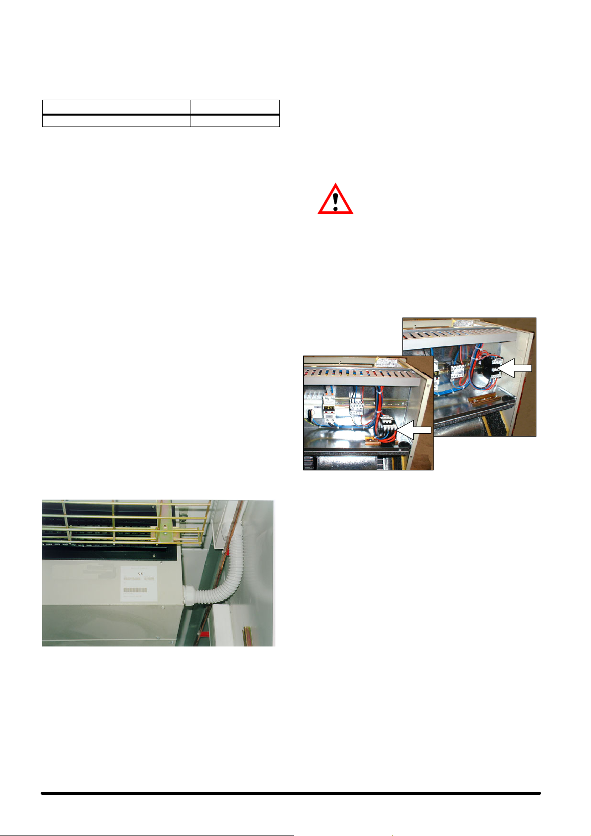
2 . 6 --- C o n e x i o n e s h i d r á u l i c a s
Durante el ciclo de refrigeración, parte de la humedad del aire
se condensa en la batería de evaporación. La humedad condensada queda recogida en un depósito colocado debajo de
la batería y se debe vaciar en el exterior.
Tab. B -- Conexiones hidráulicas (Fig. 10)
EMPALME DIMENSIONES
Descarga de la condensación φ 21 mm
Para descargar el condensado producido:
S Utilizar tubos de acero galvanizado, PVC o politeno flex-
ible.
S IMPORTANTE:NO CONECTAR ENTRE ELLAS LAS DES-
CARGAS DE MAS DE UNA MAQUINA.
S Asegurar una pendiente del 2% hacia la salida de la des-
carga.
S Comprobar que haya un sifón de descarga situado por lo
menos a 30 mm debajo del depósito de descarga (2).
S Llenar de agua el sifón de descarga vertiéndola en el
depósito de recogida del condensado.
2.7 --- Conexioneseléctricas (véaseFig. 6,
Fig. 7 y del esquema eléctrico que
se suministra con el equipo)
1) Antes de efectuar las conexiones eléctricas, cerciorarse de
que:
S los componentes eléctricos estén en buenas condiciones;
S todos los tornillos terminales estén enroscados correcta-
mente;
S la tensión de alimentación y la frecuencia correspondan a
las indicadas en la placa del equipo;
S el interruptor automático QS1 esté en posición abierta
(OFF);
S no haya componentes bajo tensión.
2) Conexiones de los cables de alimentación:
S Equipo de evaporación: el acondicionador se suministra
con el cuadro eléctrico y el tablero de bornes adecuados
para el funcionamiento controlado por microprocesador
integrado Microface.
S En el interior del cuadro eléctrico, conectar el cable de ali-
mentación principal (no suministrado para nosotros) al interruptor QS1 o a los bornes L1--- N (para la sección de los
cables de alimentación, véase Tab. 6), pasando por las
guías de cables especiales colocadas en ambos lados del
equipo.
S Para comunicar 2 o más equipos instalados en el mismo
local, dotados de control MICROFACE, con interfaz HIROMATIC, utilizar el cable HIROBUSS (se suministra con el
equipo) conectándolo tal y como se indica en el esquema
eléctrico. Asimismo, consultar el manual Microface o el
manual Hiromatic para la configuración de los equipos de
reserva.
S Equipo de motocondensación:
IMPORTANTE: EL EQUIPO DE MOTOCONDENSACION
RECIBE ALIMENTACION ELECTRICA DEL EQUIPO DE
EVAPORACION. (Consultar el esquema eléctrico que se
suministra con el acondicionador).
Conectar el cable de alimentación y el cable de alimentación auxiliar (para consultar las secciones correspondientes, véanse Fig. 7 y Fig.7a) entre los tableros de
bornes del acondicionador y del equipo de condensación
(no suministrado para nosotros estos cables).
3) El equipo de evaporación SE se produce de serie
para el montaje en el techo (Fig. G), perotambién
se puede montar sin problemas en la pared: en
este caso, el contactor KM3 del compresor
debe ser girado 90o, desenganchándolode la guía metálica (tipo ”Omega”) donde se encuentra y fijándolo en la segunda guía igual a la anterior que ya está montada
(Fig. G). De esta manera el eje del contactor se encontrará
siempre en posición horizontal. En el equipo SE provisto
de la opción DC Emergency Cooling, tanto el contactor
KM3 como el KM1 (ventiladores de corriente continua de
la sección de evaporación)deben ser girados como se ha
indicado en el párrafo anterior, utilizando la segunda guía
metálica del soporte, montada de serie.
F i g . G --- A s o f f i t t o
F i g . H --- A p a r e t e
2.8 --- Refrigeración de emergencia (opc.)
El Kit de Refrigeración de emergencia está formado por dos
ventiladores radialos de 24 ó 48 V dc y por un cuadro eléctrico
adecuado. Regular la alimentación a 48 ó 24 V dc en el interior
del cuadro eléctrico mediante un cable apantalladode sección
mínima, como se indica en la Tab. 7.
Fig. F --- Detalle de las conexiones eléctricas del SE con fijador de
S Conectar el cable de control Bus entre la tarjeta Microface
S Conectar el cable de tierra amarillo---verde.
En cuanto a los contactos de las alarmas de las distintas versiones, están disponibles en el tablero de bornes del cuadro
eléctrico, con posibilidad de activación a distancia en la caja
remota con pantalla de control. Para la descripción de las alarmas, consultar el Cap. 5 y el manual de control instalado.
cables y funda de plástico (no suministrado para nosotros)
y la pantalla remota correspondiente, pasando por las
guías de cables especiales colocadas en ambos lados y,
en algunos casos, detrás del equipo.
3 --- Puesta en marcha
3.1 --- Circuito de refrigeración
Véanse Fig. 11 y Fig. 12.
3.2---Primerapuestaenmarcha(o
Antes de poner en marcha el acondicionador es aconsejable
volver a comprobar que la tensión y la frecuencia de alimentación correspondan a las que se indican en la placa de identificación del equipo.
Una vez hecho esto, se puede poner en marcha el acondicionador poniendo el interruptor automático QS1 en la posición
ON.
Comprobar el consumo eléctrico de todos los componentes y
comparar con los datos que aparecen en las Tab. 3, Tab. 4 y
Tab. 5.
Comprobar que no haya ninguna alarma activada; esperar
3
después de una larga interrupción)
Español
Page 51

que el sistema se ponga en marcha y efectuar las siguientes
comprobaciones:
S comprobar que los ventiladores funcionencorrectamente;
S asegurarse de que la temperatura sea constante y que el
compresor y las resistencias de la calefacción funcionen
cuando sea necesario;
S asegurarsede que el reguladorde la velocidad (Variex) del
ventilador de la sección de condensación esté regulado
correctamente, y que controle el funcionamiento del ventilador (véase Cap. 4).
3.3 --- Puesta en marcha con temperatura
exterior baja
En caso de que la temperatura exterior sea baja (<0ûC), para
facilitar la puesta en marcha del equipo, éste dispone de un
tiempo de retardo de la activación de las alarmas de baja presión, en el cual las presiones del circuito de refrigeración alcanzan los valores normales de funcionamiento.
3.4 --- Puesta en marcha y parada
En los equipos que disponen de control MICROFACE, el encendido y apagado se obtienen mediante el interruptor principal QS1, al cual se accede quitando el panel superior frontal.
Para encender y apagar los equipos accionar el interruptor
QS1.
En los equipos que disponen de interfaz HIROMATIC:
S poner el equipo en marcha accionando el pulsador ON ---
OFF del Hiromatic (esto queda confirmado cuando aparece SYS.ON en la pantalla);
S apagar el equipo accionando el pulsador ON ---OFF del Hi-
romatic (esto queda confirmado cuando aparece
SYS.OFF. en la pantalla).
NOTA: apagar el interruptor principal QS1 solo si el equipo
está inactivo durante un largo periodo de tiempo.
4 --- Funcionamiento
4.1 --- Generalidades
El funcionamiento del equipo es totalmente automático. La secuencia siguiente explica como funciona el equipo (véanse
también Fig. 11 y Fig. 12 --- Circuito de refrigeración).
El sensor de temperatura colocado en la zona de aspiración,
dentro del local, informa al control de las condiciones del aire
quesedebetratar.
El control compara la información recibida con los valores de
Set Point (= temperatura interior mínima deseada) y los Diferencial programados, y configura el acondicionador para in-
iciar el tratamiento del aire, con las siguientes modalidades:
4.4 --- Refrigeración en Freecooling
(opcional)
Cuando la temperatura exterior es algún grado inferior a la
temperatura interior, esta diferencia puedeservir pararefrescar
el interior del local, mediante la introducción directa del aire exterior , sin utilizar el compresor, naturalmente. Esto permite
ahorrar un poco de energía eléctrica.
En caso de darse las condiciones previstas, el servocomando,
controladopor Microface, abre la compuerta móvil que separa
la circulación de los flujos de aire exterior e interior. De esta forma, el aire exterior aspirado por el ventilador entra y sale del
local por una compuerta de sobrepresión instalada en las paredes del local (opcional), protegida por una rejilla exterior
contra la lluvia.
El grado de apertura de la compuerta se determina en función
delvalordeSetPointquesedebemantener,ydelatemperatura del aire introducida (véase Cap. 5).
4.5 --- Regulación de la velocidad del
ventilador del condensador
Un sensor está colocado de manera que detecta constantemente la presión de condensación del gas de refrigeración. A
partir de esta información, un dispositivo electrónico (Variex)
regula la velocidad de rotación del ventilador para mantener la
presión de condensación dentro de los valores permitidos. De
esta forma, además de optimizar el funcionamiento del compresor, se obtieneuna reducción sensible del nivel de emisión
sonora (especialmente durante la noche), se facilita la puesta
en marcha del compresor en bajas temperaturas, y se ahorra
energía eléctrica. Para más información sobre el regulador de
velocidad, véase el Cap. 8.
4.6 --- Refrigeración de emergencia (opc.)
Esta opción está disponible en todas aquellas aplicaciones en
las que es importante asegurar la circulación del aire en el interior del local, incluso en caso de un corte del suministro eléctrico de la red. En este caso, los equipos se pueden alimentar
con las baterías de emergencia de 48 V dc (o 24 V dc).
La modalidad de intervención del sistema de emergencia dependedecomoestéelinterruptorautomáticoQS1:
S QS1 = ON Si no se producen interrupciones en la alimen-
tación principal, el sistema de emergencia queda inactivo;
si se interrumpe la tensión en la línea de alimentación principal, la energía se obtiene automáticamente de las baterías de emergencia de 48 V dc (o 24 V dc) y se alimentan
los ventiladores de la sección de evaporación y el control
electrónico. De esta manera, todas las funciones del equipo continúan activas, permitiendo que el aire interior circule (o el flujo de aire exterior ,si el equipo dispone del sistema Freecooling), en caso de que la temperatura interior del
local no esté entre las temperaturas permitidas.
4.2 --- Refrigeración (véase Fig. 8)
El compresory los ventiladores se ponen en marcha cuando la
temperatura del local supera el valor fijado. El aire aspiradopor
el ventilador centrifugo entra en el equipo por la rejilla posterior
(rejilla inferioren los equipos con opción Freecooling), pasainmediatamente por el filtro, y finalmente pasa por elevaporador.
El refrigerante frío pasa por el evaporador, refrigerando el aire
que atraviesa. El aire tratado llega hasta el local acondicionado
por la abertura de salida. Se elimina el calor del local, que generan los motores del acondicionador al funcionar, mediante el
condensador, que está situado en el equipo de motocondensación y, gracias al ventilador, se expulsa al exterior.
La velocidad del ventilador varía continuamente (Variex,véase
4.5) en función de la presión de condensación. Para consultar
la lógica de funcionamiento del control véase Cap. 5.
4.3 --- Calefacción (opcional)
El aire se calienta mediante las resistencias eléctricas aisladas,
que están situadas en el flujode aire y se accionan siguiendola
lógica seleccionada en el control,
El reset manual del termostato de seguridad, situado en las resistencias, debe efectuarse accediendo al equipo de evaporación por la rejilla de salida.
Español
5 --- Co n t r o l e s del
microprocesador
La máquina está disponible en cuatro configuraciones diferentes de funcionamiento:
1) equipo sólo de refrigeración;
2) equipo de refrigeración y calefacción;
3) equipo con freecooling, sólo de refrigeración;
4) equipo con freecooling, de refrigeración y calefacción.
En todas las versiones, la pantalla de controles remota y se encuentra en una caja metálica que se debe instalar dentro del
local.
5.1--- Equiposóloderefrigeración
5.1.1 -- Lógica de control
Esta opción la gestiona el control por microprocesador Microface, y en algunos casos, junto con el controlHiromatic para el
controlen pantalla de todos los parámetros de funcionamiento
del equipo (véase el manual adjunto). El algoritmo de control
se basa en una regulación de 1 grado para la refrigeración con
compresor: el control gestiona todos los retrasos de activa-
4
Page 52

ción, a fin de asegurar un funcionamiento correcto y alargar
todo lo posible la vida de la máquina.
PBand
Unidad sólo
de frío
Si hay varios equipos funcionando simultáneamente con un
mismo Set Point, la temperatura utilizada para el control es la
media de las comprobadas; además, en el funcionamiento
con compresor, la banda proporcional está dividida en partes
iguales al doble del número de equipos que forman parte del
sistema, siendo posible así la parcialización de la potencia frigorífica total disponible.
Set Refrigeración °C
Fig. I --- Funcionamiento del equipo sólo de refrigeración.
5.1.2 -- Start--Stop
Existen 2 modos para encender o apagar el equipo:
a) la introducción digital de la tarjeta Microface;
b) el pulsador ON --- OFF situado en el interfaz del Hiromatic
(opcional).
Prioridad con Hiromatic: a) y b) deben considerarse como 2
contactosen serie; el equipo puede funcionar sólo si todos los
contactos están en ON.
5.1.3 -- Gestión de las alarmas
Los 2 contactos de alarma disponibles en el tablero de bornes
del panel de control están utilizados de la siguiente manera:
1) Alarma general:
S baja presión del compresor
S alta presión del compresor (reset del presostato)
S avería del sensor
S avería de la memoria
S avería del ventilador
2) Aviso general --- indicación de varias situaciones irregulares, como las siguientes:
S alta temperatura
S baja temperatura
Notas:
S Tanto de la Alarma como del Aviso el reset se debe efectuar
manualmente en el Microface.
S Unaalarmaparaelfuncionamientodelequipoyactivael
equipo de reserva (si está instalado).
S El aviso no interrumpe el funcionamiento del equipo.
5.1.4 -- Tarjeta de alarmas opcional
Además de todo lo mencionado para la configuración
estándar, en la tarjeta de alarmas opcional hay contactos de
relé para disponer de las siguientes alarmas separadamente:
1) Alta presión y baja presión del compresor
2) Alta temperatura
3) Baja temperatura
4) Alarma de filtro sucio (si está instalado)
5) Avería del ventilador
Estas alarmas provocan la parada del equipo de la misma
manera indicada en el párrafo anterior.
La descripción completa de las alarmas se encuentra en el
manual adjunto de Microface.
5.1.5 -- Equipo de reserva
La gestión del equipo de reserva es completamente automática gracias a que es posible conectar el control Microface. Un
equipo de reserva se pone en funcionamiento si se activa una
alarma que interrumpe el funcionamiento del equipo principal;
estotambién ocurre si el equipo principalse apaga o queda eliminada del sistema por avería en el bus de conexión de los
controles.
La rotación horaria del equipo de reserva se efectúa automáticamente cada 24 horas, permitiendo con ello un desgaste homogéneo de los componentes del sistema.
Si el sistema está conectado al interfaz Hiromatic, es posible
configurar una gestión de la rotación diferente.
5.2 --- Equipo de refrigerac ión y
calefacción
5.2.1 -- Lógica de control
El algoritmo de control se basa en una regulación de 1 grado
para la calefacción y la refrigeración con compresor .
Igual que en el caso anterior, el control gestiona todos los retrasosde activación del compresor,a fin de asegurar un funcionamientocorrectoyalargartodoloposiblelavidadelamáquina.
Dead band!P@ Pband !P@ Pband
Cooling and
heating unit
Heating
Fig. J --- Funcionamiento del equipo de refrigeración + calefacción.
Set Cooling °C
5.2.2 -- Start--Stop
Véase el pár. 5.1.2.
5.2.3 -- Gestión de las alarmas
Véase el pár. 5.1.3.
Además existe otro Aviso general para indicar la siguiente
irregularidad:
S termostato de la resistencia (reset del termostato)
Notas:
S El aviso no interrumpe el funcionamiento del equipo.
S Si interviene el termostato de seguridad de las resistencias,
se debe efectuar el reset del termostato según las modalidades descritas.
5.2.4 -- Tarjeta de alarmas opcional
Véase el pár. 5.1.4.
5.2.5 -- Equipo de reserva
Véase el pár. 5.1.5.
5.3 --- Equipo con freecooling
5.3.1 -- Lógica de control
Esta opción la gestiona el control por microprocesador Microface, y en algunos casos, junto con el controlHiromatic para el
control en pantalla completo de todos los parámetros de funcionamiento del equipo (véase el manual adjunto). El algoritmo de controlse basa en una regulaciónde 1 grado para la calefacción y la refrigeración con compresor,y en una regulación
de tipo proporcional --- Integrada para la refrigeración en
modalidad Freecooling,conintroduccióndel del Set Point y de
la banda proporcional (P) (Fig. K).
El control gestiona todos los retrasos de activación del compresor, tal y como ocurría en los dos casos anteriores, a fin de
asegurar un funcionamiento correcto y alargar todo lo posible
la vida de la máquina.
La modalidad Freecooling se activa en función de la diferencia
(seleccionable) entre la temperaturainterior y exterior.Esto significa que si la diferencia entre las 2 temperaturas aumenta por
encima de un valor concreto, el equipo pasa automáticamente
a la función Freecooling: el compresor se desactiva, y la salida
analógica controla el servomotor de 3 puntos de la compuerta.
El grado de apertura de la compuerta se determina en función
de la diferencia de temperatura en el exterior y el interior , y en
función de la temperatura del aire introducido en el local, que
no puede ser inferior a un valor fijado de seguridad.
5
Español
Page 53
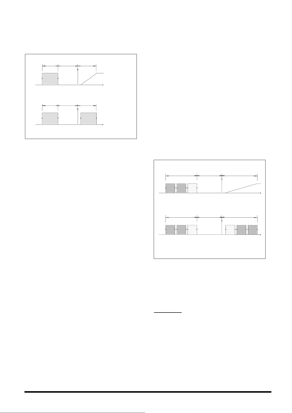
Si la temperatura interior supera la bandaproporcional en más
de un 20%, durante más de 10 minutos, el equipo pasa a la refrigeración con compresor, y la modalidad Freecooling queda
desactivada durante
1
/2hora. Si la temperatura interior supera
la banda proporcional en más de un 50%durante más de 2 minutos, la modalidad Freecooling queda desactivada durante
1
/2horas y se procede a la refrigeración mediante el compresor
de refrigeración.
Dead band!P@ Pband !P@ Pband
Set
CoolingHeating °C
Dead band!P@ Pband !P@ Pband
Set
CoolingHeating °C
Fig. K - -- Funcionamiento del compresor, las resistencias
eléctricas y apertura de la compuerta de Freecooling.
Freecooling
mod
e
Comprescooling mode
sor
5.3.2 -- Start--Stop
Existen 2 modos para encender o apagar el equipo:
a) la introducción digital de la tarjeta Microface;
b) el pulsador ON ---OFF situado en el interfaz del Hiromatic
(opcional).
Prioridad con Hiromatic: a) y b) deben considerarse como 2
contactosen serie; el equipo puede funcionar sólo si todos los
contactos están en ON.
3) Baja temperatura
4) Alarma de filtro sucio (si está instalado)
5) Avería del ventilador
Estas alarmas provocan la parada del equipo de la misma
manera indicada en el párrafo anterior.
La descripción completa de las alarmas se encuentra en el
manual adjunto de Microface.
5.3.5 -- Equipo de reserva
La gestión del equipo de reserva es completamente automática gracias a que es posible conectar el control Microface. Un
equipo de reserva se pone en funcionamiento si se activa una
alarma que interrumpe el funcionamiento del equipo principal;
estotambién ocurre si el equipo principalse apaga o queda eliminado del sistema por avería en el bus de conexión de los
controles.
La rotación horaria del equipo de reserva se efectúa automáticamente cada 24 horas, permitiendo con ello un desgaste homogéneo de los componentes del sistema.
Si el sistema está conectado al interfaz Hiromatic, es posible
configurar una gestión de la rotación diferente.
Si hay varios equipos funcionando simultáneamente con un
mismo Set Point, la temperatura utilizada para el control es la
media de las comprobadas; además, en el funcionamiento
con compresor, la banda proporcional está dividida en partes
iguales al doble del número de equipos que forman parte del
sistema, siendo posible así la parcialización de la potencia frigorífica total disponible.
El funcionamiento en modalidad Freecooling es homogéneo y
simultáneo en todos los equipos.
La Fig. L, por ejemplo,representa el funcionamiento de un sistema compuesto por 3 equipos.
Freecooling mode
1
Dead band
Cooling
Set °C
!P@ Pband !P@ Pband
2
3
Heating
5.3.3 -- Gestión de las alarmas
Los 2 contactos de alarma disponibles en el tablero de bornes
del panel de control están utilizados de la siguiente manera:
1) Alarma general:
S baja presión del compresor
S alta presión del compresor (reset del presostato)
S avería del sensor
S avería de la memoria
S avería del ventilador
2) Aviso general --- indicación de varias situaciones irregu-
lares, como las siguientes:
S alta temperatura
S baja temperatura
S termostato de la resistencia (reset del termostato)
Notas:
S tantodelaAlarmacomodelAvisoelresetsedebenefec-
tuar manualmente en el Microface.
S Unaalarmaparaelfuncionamientodelequipoyactivael
equipo de reserva (si está instalado). Si el equipo funciona
de forma autónoma, las alarmas de alta y baja presión no
interrumpen el funcionamiento de la máquina para permitir
el funcionamiento en modalidad Freecooling cuando las
condiciones sean adecuadas.
S el aviso no interrumpe el funcionamiento del equipo.
S Si interviene el termostato de seguridad de las resistencias,
se debe efectuar el reset del termostato según las modalidades descritas.
5.3.4 -- Tarjeta de alarmas opcional
Además de todo lo mencionado para la configuración
estándar, en la tarjeta de alarmas opcional hay contactos de
relé para disponer de las siguientes alarmas separadamente:
1) Alta presión y baja presión del compresor
2) Alta temperatura
Compressor cooling mode
!P@ Pband !P@ Pband
3
223
Heating
1 = main unit
2 = unit in stand --- by
3 = unit in stand --- by
Fig. L - -- Sistema compuesto por 3 equipos totales, de los cuales
2 son de reserva --- Control Microface
Dead band
11
Set
Cooling
°C
6 --- Carga de refrigerante
R22
IMPORTANTE: LAS OPERACIONES SIGUIENTES DEBE
EFECTUARLAS UN TECNICO FRIGORISTA ESPECIALIZADO.
EL EQUIPO SE SUMINISTRA PREVIAMENTE CARGADO
CON NITROGENO.
6.1 --- Características del líquido de
refrigeración R22
Con una temperatura y una presión normales, se trata de un
gas incoloro de baja toxicidad, no inflamable, con un valor
máximo de exposición permitido (AEL/TLV) igual a 1000 rpm
(valormedio ponderado en 8 horasdiarias). En caso de producirse un escape, ventilar el local antes de permanecer dentro.
Español
6
Page 54
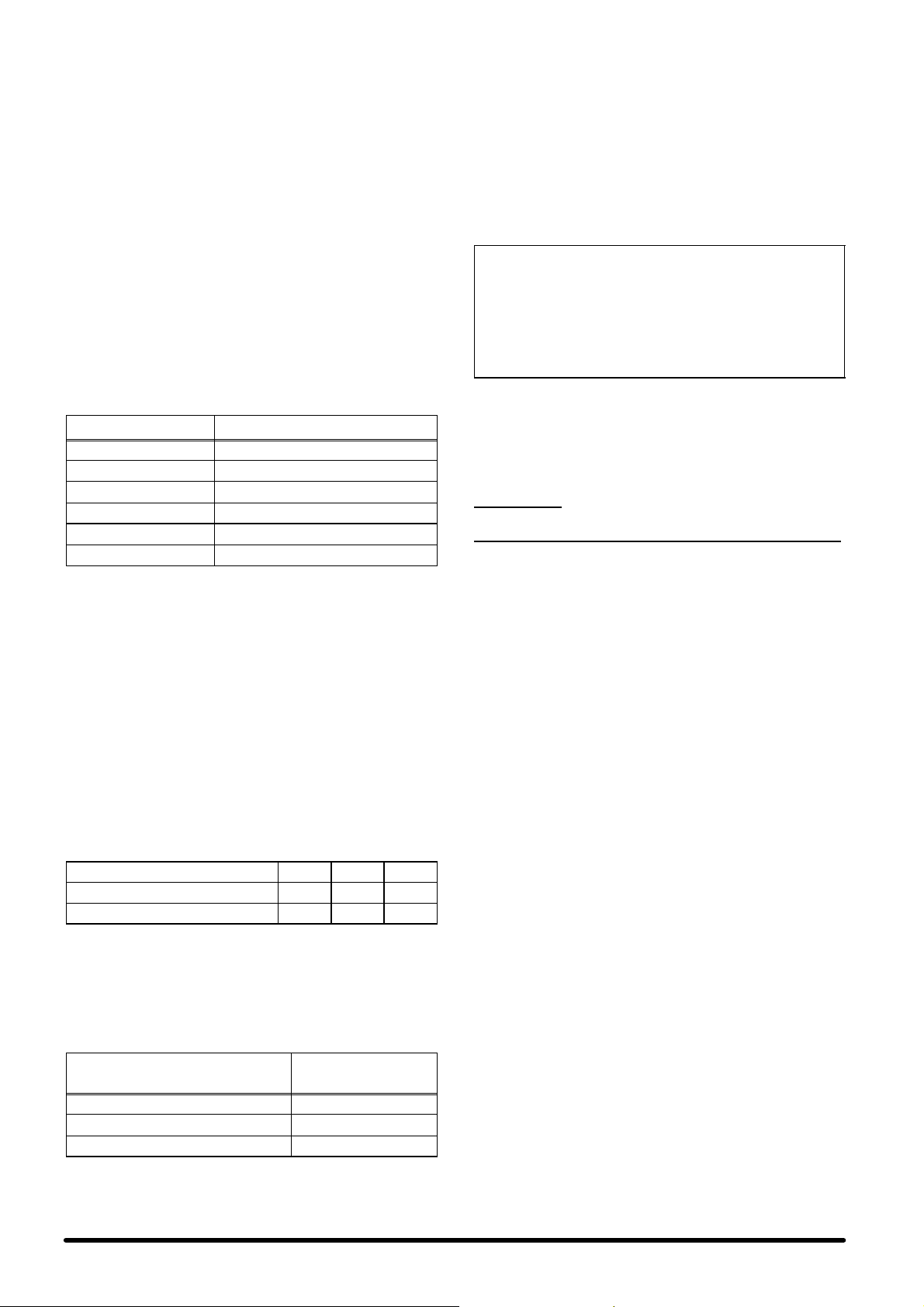
6.2 --- Carga de refrigerante R22
CUANDO SE REPARA EL CIRCUITO DE REFRIGERACIÓN
SE DEBE RECOGER EL REFRIGERANTE EN UN CONTENEDOR: NO SE DEBE DISPERSAR EN EL MEDIO AMBIENTE.
1) Una vez conectados los circuitos de refrigeración a las vías
principales de los grifos situados en el equipo de evaporación y motocondensción, evacuar el nitrógeno cargado
previamente por la vía correspondiente ¼” SAE, equipada
con una válvula de aguja, situada en el equipo de motocondensación.
2) Vaciar el circuito con la bomba de calidad especial para el
vacío, haciendo un vacío di 0,7 mbar absoluto
3) Después de 3 horas comprobar que el valor no supere 1,3
mbar absolutos. Si el vacío no es mantenido, hay perdidas
en el sistema. Reparar el circuito y repetir las operaciones
del punto 2.
4) Conectar el cilindro de carga en el circuito de líquidos del
equipo de motocondensación, y empezar a cargar la cantidadderefrigeranteR22queseindicaenTab.C.
Tab. C -- Carga de refrigerante R22 para una dis-
Hisp SE+SC05 2.2
Hisp SE+SC06 2.5
Hisp SE+SC08 4.3
Hisp SE+SC10 4.4
Hisp SE+SC13 4.4
Hisp SE+SC14 4.4
5) Cuando no sea posible efectuar la carga completa, mover
el cilindro de aspiración del compresor, y finalizar la carga.
En cualquier caso, una vez finalizada procedercomo se indica a continuación:
6) Poner en marcha el equipo, como se indica en el párrafo
3.2.
7) Poner en marcha el compresor manualmente.
8) Asegurar una temperatura de condensación constante
(preferentemente de 50°C); si es necesario, tapar parcialmente la superficie de intercambio del condensador, para
obtener estas condiciones.
9) Esperar a que las condiciones de funcionamiento de todo
el circuito de refrigeración sean normales.
10) Con el equipo enfuncionamiento,comprobarque el sobrecalentamiento respete los valores que se indican en la siguiente Tab. D (se indican las temperaturas del manómetro)
Tab. D -- Tabla del sobrecalentamiento R22
Temperatura interior °C 24 27
Humedad interior %HR 50 50
Sobrecalentamiento del compresor °C 8 12
Valores correspondientes a la T condensación = 50°C
Para distancias del circuito de refrigeración superiores a 5 m e
inferiores a 15 m, aumentar la carga del circuito tal y como se
indica en la siguiente Tab. E:
Tab. E -- Carga adicional de refrigerante R22 para
Diámetro del tubo del líquido
8 mm (exterior tubo) 30
10 mm (exterior tubo) 53
12 mm (exterior tubo) 70
Valores correspondientes a la T condensación = 50°C
tancia de 5 m entre el evaporador y el
equipo de motocondensación.
MODELO Carga de refrigerante R22 [kg]
un metro de distancia adicional (más de
5mhasta15m)
Carga de refriger-
ante R22 [g/m]
NOTA: la distancia hace referencia a la longitudde lastuberías,
incluyendo las curvas, entre los equipos interior y exterior,sólo
en el circuito del líquido (no sumar ida + vuelta).
6 . 3 --- C a r g a d e ac e i t e
El aceite utilizado para el llenado es el SUNISO 3GS; si no
se encuentra disponible SUNISO 3GS, utilizar un aceite de
las mismas características (ver Tab. F).
NO MEZCLAR NUNCA ACEITES DISTINTOS. DRENAR Y
LIMPIAR LAS CONDUCCIONES ANTES DE CAMBIAR EL
TIPO DE ACEITE UTILIZADO.
Tab. F -- Aceite Suniso 3GS (estándar)
peso específico aproximado (a 15_C)
punto de inflamabilidad (C.O.C.)
punto de derrame
viscosidad ENGLER a 50_C
índice de viscosidad
corrosión sobre cobre (100_C, 3 horas) ASTM D130
valor de neutralización
residuo carbónico conradson
rigidez dieléctrica
:
0,91 kg/l
:
170_C
:
--- 4 0 _C
:
2,7 E
:
0
:
1
:
0,03 max.
:
0%
:
>30kV
7 --- Carga de refrigerante
R407C
IMPORTANTE: ESTAS OPERACIONES DEBE EFECTUARLAS UN TECNICO FRIGORISTA.
EL EQUIPO SE ENTREGA CON CARGA DE
7.1 --- Características del líquido de
refrigeración R407C
Con una temperatura y una presión normales, se trata de un
gas incoloro de baja toxicidad, no inflamable, con un valor
máximo de exposición permitido (AEL/TLV) igual a 1000 rpm
(valormedio ponderado en 8 horasdiarias). En caso de producirse un escape, ventilar el local antes de permanecer dentro.
7.2 --- Carga de refrigerante R407C
CUANDO SE REPARA EL CIRCUITO DE REFRIGERACION
SE DEBE RECOGER EL REFRIGERANTE EN UN CONTENEDOR: NO SE DEBE DISPERSAR EN EL MEDIO AMBIENTE.
1) Una vez los circuitos de refrigeración están conectados a
los conductos principales de los grifos del equipo de evaporación y de motocondensación, descargar el nitrógeno
previamente cargado mediante el conducto correspondiente ¼” SAE, equipado con válvula de aguja, del equipo
de motocondensación.
2) Vaciar el circuito con la bomba de calidad especial para el
vacío, haciendo un vacío di 0,3 mbar absoluto
3) Después de 3 horas comprobar que el valor no supere 1,3
mbar absolutos.Si el vacío no es mantenido, hay perdidas
en el sistema. Reparar el circuito y repetir las operaciones
del punto 2.
4) Conectar el cilindro de carga en el circuito de líquido del
equipo de motocondensación y empezar a cargar la cantidad de refrigerante R407C indicada en Tab. G.
5) Poner en marcha el compresor manualmente.
6) Asegurar una temperatura de condensación constante
(preferentemente de 50°C); si es necesario, tapar parcialmente la superficie de intercambio del condensador, para
obtener estas condiciones.
NITROGENO
7
Español
Page 55

Tab. G -- Carga de refrigerante R407C si la distan-
cia entre el equipo de evapo racióny el de
motocondensación es de 5 m.
MODELO Carga de refrigerante R407C [kg]
Hisp SE+SC05 2.2
Hisp SE+SC06 2.5
Hisp SE+SC08 4.3
Hisp SE+SC10 4.4
Hisp SE+SC13 4.4
Hisp SE+SC14 4.4
7) Cuando no sea posible efectuar la carga completa, desplazar el cilindro de aspiración del compresor,y finalizarla carga. En cualquier caso, una vez finalizada proceder como
se indica a continuación:
8) Ponerenmarchaelequipocomoestádescritoenelpárrafo
3.2.
9) Esperar a que las condiciones de funcionamiento de todo
el circuito sean normales.
10) Comprobar que durante el funcionamiento el sobrecalentamiento esté dentro de los valores indicados a continuación T ab. H (están indicadas las temperaturas manométricas)
Ta b. H -- Tabla con valores de sobrecalentamien-
to R407C
Temperatura interior °C 24 27
Humedad interior %RH 50 50
Sobrecalentamiento del compresor °C 8 12
Valores relativos a T condensación = 50°C
Si la longitud de los circuitos de refrigeración es superior 5 metros e inferior a 15, deberá aumentarse la carga introducida en
el circuito según lo indicado a continuación Tab. I:
Tab. I -- Carga adicional de refrigerante R407C
por metro de longitud adicional (más de
5myhasta15m)
Diámetro del tubo del líquido
8 mm (exterior tubo) 30
10 mm (exterior tubo) 53
12 mm (exterior tubo) 70
Valores relativos a T de condensación = 50°C
NOTA:pordistanciaseentiendelalongituddelastuberías,incluyendo las curvas, entre el equipo interior y el exterior, refiriéndose sólo al circuito del líquido (no sumar ida + retorno).
Carga de refrigerante R407C [g/m]
7 . 3 --- C a r g a d e ac e i t e
El aceite utilizado para el llenado es el MOBIL EAL ARCTIC
22CC; si no se encuentra disponible MOBIL EAL ARCTIC
22CC, utilizar un aceite de las mismas características (ver
Tab. J).
NO MEZCLAR NUNCA ACEITES DISTINTOS. DRENAR Y
LIMPIAR LAS CONDUCCIONES ANTES DE CAMBIAR EL
TIPO DE ACEITE UTILIZADO.
Tab. J -- Aceite Mobil Eal Arctic 22CC
peso específico aproximado (a 15_C)
punto de inflamabilidad (C.O.C.)
punto de derrame
índice de viscosidad
viscosidad a 40_C
viscosidad a 100_C
(estándar)
:
0,99 kg/l
:
245_C
:
< --- 5 4 _C
:
116
:
23.6 cST
:
4.7 cST
Los grifosdel compresor sólo deben abrirsedespués de haber
puesto a vacío y a carga parcial toda la instalación.
Español
8
Page 56

8 --- Ta r a d o s
El acondicionador de aire viene tarado y comprobado de fábrica tal como se indica a continuación.
COMPONENTE
Presostato de baja presión
(LP)
Presostato de alta presión
(HP)
Control de la velocidad
del ventilador
(BV)
STOP : 1 bar
START : 2 bar
(tarados fijos)
STOP : 28 bar
START : 20 bar
(tarados fijos)
SET. : 18.8 bar
BAND P : 3,8 bar
(Paralaregulaciónvéanse
instrucciones adjuntas al
bordedelamáquina)
TARADOS NOTAS
9 --- Mantenimiento / Recambios
reset
automático
reset
manual
accionando el pulsador
Porrazonesde seguridad,se puede interrumpir la tensióndel equipo, abriendoel interruptorQS1 antes deefectuar cualquier operación de mantenimiento.
El Programa de Mantenimiento indicado a continuación debe ser llevado a cabo por un técnico especializado, que a ser posible
disponga de un contrato de mantenimiento.
Programa de mantenimiento --- Control mensual
Comprobar que el motor del ventilador gire libremente, sin ruidos irregulares y que no
VENTILADORES
FILTROS DE AIRE
CIRCUITO ELECTRICO
CIRCUITO DE
REFRIGERACION
9.1 --- Desguazado del equipo
Esta máquina ha sido diseñada y fabricada para garantizar un
funcionamiento continuado. La duración de algunos de los
componentes principales, como el ventilador o el compresor,
depende de su mantenimiento.
Sóloun técnico frigoristaespecializadopodrá proceder aldesguazado del equipo.
El fluido de refrigeración y el aceite lubricante que contiene el
circuito deberán reciclarse, de acuerdo con las normas vigentes en el país de instalación.
se sobrecalienten los rodamientos.
Comprobar también el consumo de corriente.
Comprobar el estado del filtro; si es necesario, limpiarlo o sustituirlo. Para sustituirlo:
S extraer el panel inferior del equipo
S extraer la escuadra de fijación y extraer verticalmente el filtro de su posición
S colocar el recambio
S volver a colocar y fijar la escuadra y cerrar el panel
En locales con mucho polvo, realizar este control con mucha frecuencia.
S Comprobar la alimentación eléctrica en todas las fases.
S Comprobarquelasconexioneseléctricasesténbienapretadas.
S Comprobar las presiones de evaporación (se debe encargar un frigorista exper-
to).
S Controlar el consumo de corriente del compresor, la temperatura inicial y la pres-
encia de ruidos irregulares.
S Comprobar que no se forme hielo en el evaporador
9 . 2 --- R e c a m b i o s
Se aconseja utilizar piezas de recambio originales.
Si se desea solicitar piezas, consultar la “Component List” que
se entrega con la máquina y especificar el modelo y el número
de serie del equipo.
9
Español
Page 57

10 --- A p é n d i c e
10.1 --- Comprobación del equipo después de la instalación
En la siguiente lista aparecen los controles quese deben efectuarpara comprobarelbuen estadode Hisp después dela instalación.
IMPORTANTE: TODOS LOS EQUIPOS HAN SIDO PROBADOS EN NUESTROS PLANTAS ANTES DE LA ENTREGA.
A) COMPROBACION ESTATICA
A.1) Equipo de evaporación SE
A.1.a) Comprobar visualmente el buen estado de
los paneles y su fijación; y el buen estado de
los rebordes.
A.1.b) Comprobar que haya una descarga de la
condensación en cada máquina, dotada de
un sifón con un amplio radio del codo.
A.1.c) Comprobar la presencia y la fijación de los
conductos (rígidos o flexibles) de aspiración
del aire del Freecooling (opcional) y de la rejilla exterior de protección contra la lluvia, equipada con un prefiltro metálico (opc.).
A.1.d) Comprobar la presencia y el funcionamiento
correcto (movilidad de las aletas) de la compuerta de sobrepresión, para expulsar el aire
del Freecooling (opc.), equipada con una rejilla exterior de protección contra la lluvia.
A.1.e) Comprobar la fijación al techo o a la pared del
equipo, y la impermeabilidad de todas las fijaciones que atraviesen las paredes del local
quesedebeacondicionar.
A.1.f) Acceder al cuadro eléctrico del local y colo-
carlo en la posición “OFF”.
A.1.g) Extraer los paneles inferiores de inspección
para acceder al interior del equipo de evaporación.
A.1.h) Acceder al cuadro eléctrico y colocar en la
posición “0” el interruptor principal QS1 de
alimentación de la red.
A.1.i) Comprobar que no haya cuerpos extraños en
el cuadro eléctrico.
A.1.l) Comprobar la conexión correcta de los ca-
bles de alimentación y el cable Bus entre Microface y la pantalla remota.
A.1.m) Comprobar la fijación y la polaridad de los ca-
bles para la alimentación de emergencia (baterías) en el inversor. En caso de dudas, consultar el esquema eléctrico. IMPORTANTE:
non modificar la regulación de los potenciómetros en la tarjeta del inversor.
A.1.n) Comprobar la fijación de los cables, los com-
ponentes electrónicos y los fusibles.
A.1.o) Comprobar el estado el ventilador de evapo-
ración, moviéndolo con la mano: debe poder
girar libremente sin hacer ningún ruido extraño. El eje debe estar alineado.
A.1.p) Comprobar la posición correcta del filtro del
aire.
A.1.q) Comprobar el buen estado y la fijación de la
compuerta del Freecooling (en caso de estar
instalado).
A.1.r) Comprobar la orientación de las aletas de sa-
lida, en función de las necesidades.
A.1.s) Comprobar la posición correcta de las resi-
stencias eléctricas de calefacción (opcionales) en el flujo del aire, asegurándose de que
no estén en contacto con las paredes del
acondicionador o con otros componentes.
A.2) Equipo de motocondensación SC
A.2.a) Extraer los paneles frontal y lateral para acce-
der al circuito de refrigeración (siempre que
las condiciones atmosféricas lopermitan: evitar que entre agua en el cuadro eléctrico o en
la caja del compresor).
A.2.b) Comprobar el buen estado del circuito de re-
frigeración, asegurándose de que no haya
manchas de aceite en la caja del compresory
en las tuberías.
A.2.c) Comprobar el estado del ventilador de con-
densación, moviéndolo con un destornillador: debe poder girar libremente sin hacer
ningún ruido extraño.
A.1.i) Comprobar que no haya cuerpos extraños en
el cuadro eléctrico, la conexión correcta al
equipo de evaporación y que todas las conexiones eléctricas estén fijadas.
El equipo está preparado para comprobación dinámica.
B) COMPROBACION DINAMICA
B.1) Volver a cerrar los paneles de inspección del
equipo de evaporación, menos el panel de
acceso al cuadro eléctrico.
B.2) Comprobar la conexión a tierra.
B.3) Acceder al cuadro eléctrico del local y colo-
carlo en la posición “ON”.
B.4) Acceder al cuadro eléctrico del equipo de
evaporación y colocar en la posición “1” el in-
terruptor principal QS1 de alimentación de la
red.
B.5) Comprobar la tensión de los cables de ali-
mentación principal.
B.6) Comprobar la tensión de los cables de ali-
mentación de emergencia.
B.7) Introducir la configuración deseada del siste-
ma en la pantalla de control Microface (o Hiro-
matic) como, por ejemplo, set point, network
(asignando un número de identificación a ca-
da equipo), parámetros compartidos, reser-
va, diferenciales de Freecooling (en caso de
estar instalado), etc.
B.8) Poner la máquina en marcha y calcular el
consumo de corriente del ventilador de eva-
poración, únicamente.
B.9) Poner en marcha el compresor (en caso de
ser necesario, forzar el sistema desde el con-
trol) y esperar que el sistema se estabilice.
Calcular el consumo de corriente, con el ven-
tilador y el compresor en funcionamiento.
B.10) Comprobar todos estos valores, y comparar-
los con los OA (Operating Ampère), que apa-
recenenesteManualparaevitarconsumos
eléctricos inadecuados.
B.11) Comprobar la temperatura de salida con un
termómetro digital.
B.12) Comprobar el sobrecalentamiento, según la
Tab. 10.
B.13) Desconectar la alimentación principal (desde
el cuadro eléctrico del local) y comprobarque
el inversor se active automáticamente.
B.14) Volver a regular correctamente los paráme-
tros de control.
B.15) Volver a cerrar los paneles del equipo de eva-
poracióny del equipo de motocondensación.
A.1.s) Verificare il corretto posizionamento delle re-
sistenze elettriche di riscaldamento (opziona-
li) nel flusso d’aria, controllando che non sia-
no a contatto con le pareti del condizionatore
o con altri componenti.
Español
10
Page 58

Page 59

РспейдпрпйзфйкЭт хрпдеЯоейт
”õМИЫЩФýÌÙ·È Ù· ð·Ò·Í‹Ùù:
S ЦхлЬофе фп рбсьн егчейсЯдйп гйб чсЮуз кби’ ьлз фз дйЬскейб жщЮт фпх мзчбнЮмбфпт
S дйбвЬуфе рспуекфйкЬ фп егчейсЯдйп рсйн брь кЬие есгбуЯб уфп мзчЬнзмб.
S Tп ухгкексймЭнп мзчЬнзмб рсЭрей нб чсзуймпрпйеЯфбй мьнп гйб фп укпрь гйб фпн прпЯп рсппсЯжефбй. Уе ресЯрфщуз
еуцблмЭнзт чсЮузт, п кбфбукехбуфЮт ден бнблбмвЬней кбмЯб ехиэнз.
Фп рбсьн егчейсЯдйп рсппсЯжефбй гйб фпн фелйкь чсЮуфз мьнп гйб есгбуЯет рпх еЯнбй дхнбфь нб екфелеуфпэн ме
клейуфЬ фб рлбЯуйб фпх мзчбнЮмбфпт. Пй есгбуЯет гйб фйт прпЯет брбйфеЯфбй фп Ьнпйгмб фщн рлбйуЯщн ме есгблеЯб, иб
рсЭрей нб екфелпэнфбй мьнп брь ейдйкехмЭнп фечнйкь рспущрйкь. КЬие мзчЬнзмб еЯнбй ецпдйбумЭнп ме мйб дйЬфбоз
брпмьнщузт фпх злекфсйкпэ сеэмбфпт рпх ерйфсЭрей уфп чейсйуфЮ нб есгбуиеЯ хрь буцблеЯт ухниЮкет П дйЬфбоз
бхфЮ рсЭрей нб чсзуймпрпйеЯфбй рЬнфпфе гйб фзн еоЬлейшз рйибнюн кйндэнщн кбфЬ фз дйЬскейб фщн есгбуйюн
ухнфЮсзузт (злекфспрлзоЯб, егкбэмбфб, бхфьмбфз ербнеккЯнзуз, фмЮмбфб рпх всЯукпнфбй уе кЯнзуз кбй
фзлечейсйумьт). Фп ейдйкь клейдЯ гйб фзн бцбЯсеуз фщн рлбйуЯщн, рпх рбсЭчефбй брь фз Hiross мбжЯ ме фпн еопрлйумь,
рсЭрей нб цхлЬууефбй брь фп бсмьдйп рспущрйкь есгбуйюн ухнфЮсзузт.
Гйб фзн бнеэсеуз фщн рспудйпсйуфйкюн уфпйчеЯщн фпх мзчбнЮмбфпт (мпнфЭлп кбй бсйимьт уейсЬт), уе ресЯрфщуз рпх
чсейЬжеуфе фечнйкЮ хрпуфЮсйоз Ю бнфбллбкфйкЬ, дйбвЬуфе фзн рйнбкЯдб фщн уфпйчейюн бнбгнюсйузт рпх всЯукефбй
уфесещмЭнз уфп еущфесйкь Ю уфп еощфесйкь фмЮмб фзт мпнЬдбт .
—–œ”œ◊«: фп рбсьн егчейсЯдйп еЯнбй рспкбфбскфйкь кбй ендЭчефбй нб хрпвлзиеЯ уе бллбгЭт. Щт ек фпэфпх, гйб
рлЮсейт кбй ензмесщмЭнет рлзспцпсЯет п чсЮуфзт иб рсЭрей рЬнфб нб бнбфсЭчей уфп егчейсЯдйп рпх рбсЭчефбй мбжЯ
ме фп мзчЬнзмб
—ßМ·Н·Ъ рВТИВ˜ФП›МùÌ
1 -—ТФН·Щ·ТНЩИН›Ъ ВТ„·ЫßÂÚ 1....................................................................
1.1 - Рсьлпгпт 1......................................................................................
1.2 - Елегчпт кбфЬуфбузт мзчбнЮмбфпт 1..............................................................
1.3 - МефбцпсЬ 1.....................................................................................
1.4 - Уфегбньфзфб чюспх 1............................................................................
1.5 - ¼сйб лейфпхсгЯбт 1...............................................................................
1.6 - РесйпчЭт есгбуйюн ухнфЮсзузт 1..................................................................
2- ≈„Í·Ù‹ÛÙ·ÛÁ 1..............................................................................
2.1 - УхнплйкЭт дйбуфЬуейт 1...........................................................................
2.2 - ФпрпиЭфзуз фзт еущфесйкЮт мпнЬдбт 1............................................................
2.3 - УхндЭуейт бесбгщгюн ухуфЮмбфпт Freecooling (рспбйсефйкь) 1.......................................
2.4 - ФпрпиЭфзуз фзт мпнЬдбт ухмрэкнщузт 2..........................................................
2.5 - ШхкфйкЭт ухндЭуейт 2.............................................................................
2.6 - ХдсбхлйкЭт ухндЭуейт 3..........................................................................
2.7 - ЗлекфсйкЭт ухндЭуейт (влЭре Fig. 6, Fig. 7 кбй фп дйЬгсбммб ухндеумплпгЯбт
2.8 - ЕцедсйкЮ шэоз (рспбйс.) 4.........................................................................
3- ≈ÍÍßÌÁÛÁ 4..................................................................................
3.1 - Шхкфйкь кэклщмб 4...............................................................................
3.2 - Рсюфз еккЯнзуз (Ю мефЬ брь рбсбфефбмЭнз дйбкпрЮ лейфпхсгЯбт) 4...................................
3.3 - ЕккЯнзуз ме чбмзлЮ еощфесйкЮ иесмпксбуЯб 4......................................................
3.4 - ЕккЯнзуз кбй дйбкпрЮ лейфпхсгЯбт 4................................................................
4- АВИЩФõÒ„ß· 4................................................................................
4.1 - ГенйкЭт рлзспцпсЯет 4............................................................................
4.2 - Шэоз (влЭре Fig. 8) 4..............................................................................
4.3 - ИЭсмбнуз (рспбйсефйкь) 4.........................................................................
4.4 - Шэоз ме лейфпхсгЯб Freecooling (рспбйсефйкь) 4......................................................
4.5 - Сэимйуз фзт фбчэфзфбт фпх бнемйуфЮсб фпх ухмрхкнщфЮ 5.........................................
4.6 - ЕцедсйкЮ шэоз (рспбйс.) 5.........................................................................
5 - EОВ„˜ФИ ПВ ПИНТФВрВУВТ„·ЫЩÞ 5............................................................
5.1 - МпнЬдб мьнп шэозт 5.............................................................................
5.2 - МпнЬдб шэозт кбй иЭсмбнузт 6....................................................................
5.3 - МпнЬдб ме лейфпхсгЯб Freecooling 6................................................................
6- —ÎЮТщЫБ ¯хНЩИНФэ R22 7....................................................................
6.1 - ЧбсбкфзсйуфйкЬ фпх шхкфйкпэ хгспэ R22 7.........................................................
6.2 - РлЮсщуз шхкфйкпэ R22 7..........................................................................
6.3 - РлЮсщуз лбдйпэ 8................................................................................
7- —ÎЮТщЫБ ¯хНЩИНФэ R407C 8.................................................................
7.1 - ЧбсбкфзсйуфйкЬ фпх шхкфйкпэ хгспэ R407C 8.......................................................
7.2 - РлЮсщуз шхкфйкпэ R407C 8.......................................................................
7.3 - РлЮсщуз лбдйпэ 9................................................................................
8- –хЛПЯЫВИЪ 9.................................................................................
9- ”хМЩЮТБЫБ/¡МЩ·ОО·НЩИН‹ 9.................................................................
9.1 - БрпоЮлщуз фзт мпнЬдбт 9........................................................................
9.2 - БнфбллбкфйкЬ 9..................................................................................
10 - —·Ò‹ÒÙÁÏ· 10................................................................................
10.1 - Eлегчпт фзт мпнЬдбт мефЬ фзн егкбфЬуфбуз 10....................................................
рпх рбсЭчефбй ме фз мпнЬдб) 3....................................................................
Page 60

1 - —ТФН·Щ·ТНЩИН›Ъ
ÂÒ„·ÛßÂÚ
1.1 - —Ò¸ÎÔ„ÔÚ
Фп рбсьн егчейсЯдйп ресйлбмвЬней рлзспцпсЯет учефйкЬ ме
фзн егкбфЬуфбуз, фз лейфпхсгЯб кбй фз ухнфЮсзуз фпх
клймбфйуфйкпэ HISP, фп прпЯп брпфелеЯфбй брь мЯб мпнЬдб
еоЬфмйузт (SE, Split-Еvaporating) рпх фпрпиефеЯфбй уфпн
еущфесйкьчюспкбйбрьмЯбмпнЬдбухмрэкнщузт(SC,
Split-Condensing) рпх фпрпиефеЯфбй уфпн еощфесйкь чюсп.
”«Ã¡Õ‘…#œ:
БнбфсЭофе ерЯузт уфп егчейсЯдйп фзт мпнЬдбт елЭгчпх
Microface рпх рбсЭчефбй ме фп мзчЬнзмб (ецьупн еЯнбй
егкбфеуфзмЭнп):
1.2 - ≈΄˜ÔÚ Í·Ù‹ÛÙ·ÛÁÚ
ÏÁ˜·ÌÞÏ·ÙÔÚ
КбфЬ фзн рбсблбвЮ фпх мзчбнЮмбфпт, елЭгофе бмЭущт фзн
кбфЬуфбуЮ фпх. Гйб фхчьн жзмйЬ, ерйкпйнщнЮуфе бмЭущт ме
фз мефбцпсйкЮ ефбйсЯб.
1.3 - ÃÂÙ·ˆÔÒ‹
S ФпрпиефеЯфе фз мпнЬдб рЬнфпфе ьсийб уе кбфбкьсхцз
иЭуз кбй мзн фзн бцЮнефе екфеиеймЭнз уе бкЬлхрфпхт
чюспхт.
S КбфЬ фз мефбцпсЬ, нб брпцеэгефбй з Ьукзуз рЯеузт
уфйт ерЬнщ гщнЯет фзт ухукехбуЯбт.
S БрпухукехЬуфе фйт мпнЬдет ьуп гЯнефбй рйп кпнфЬ уфп
узмеЯп егкбфЬуфбузт. МефЬ фзн брпухукехбуЯб иб
рсЭрей нб брпцеэгпнфбй фхчьн чфхрЮмбфб рпх еЯнбй
дхнбфь нб ерзсеЬупхн фб еущфесйкЬ еобсфЮмбфб.
1.4 - ”Ù„·Ì¸ÙÁÙ· ˜þÒÔõ
Гйб фзн ерЯфехоз уфбиесюн хгсп-иесмпмефсйкюн ухнизкюн
уфпн клймбфйжьменп чюсп, енесгЮуфе щт еоЮт:
S БрбйфеЯфбй з дзмйпхсгЯб цсЬгмбфпт хдсбфмюн уфпхт
фпЯчпхт, уфп дЬредп кбй уфзн пспцЮ чсзуймпрпйюнфбт
кЬрпйп уфегбнщфйкь хлйкь.
S ДйбуцблЯуфе фзн беспуфегбньфзфб фпх дщмбфЯпх
уфегбнпрпйюнфбт фхчьн бнпЯгмбфб, ейуьдпхт
кблщдЯщн, к.л.р.
1.5 - ºТИ· ОВИЩФõÒ„ß·Ú
Пй мпнЬдет Эчпхн учедйбуфеЯ гйб нб лейфпхсгпэн енфьт фщн
ендедейгмЭнщн псЯщн лейфпхсгЯбт (влЭре Tab. 1). Фб
ухгкексймЭнб üñéá бнбцЭспнфбй óå мзчбнЮмбфб
кбйнпэсгйбт кбфбукехЮт фб прпЯб Эчпхн егкбфбуфбиеЯ
ущуфЬ Ю гйб мзчбнЮмбфб рпх хрькейнфбй уе ущуфЭт
есгбуЯет ухнфЮсзузт. Пй ьспй фзт еггэзузт кбиЯуфбнфбй
Ькхспй гйб фхчьн влЬвз Ю еуцблмЭнз лейфпхсгЯб рпх
ендЭчефбй нб рбспхуйбуфеЯ кбфЬ фз дйЬскейб Ю ео бйфЯбт
лейфпхсгйюн екфьт фщн фймюн ецбсмпгЮт.
1.6 - —ÂÒÈÔ˜›Ú ÂÒ„·ÛÈþÌÛхМЩЮТБЫБЪ
Уфз мпнЬдб иб рсЭрей нб рспвлЭрефбй п кбфЬллзлпт чюспт
гйб ôéò есгбуЯет ухнфЮсзузт, ьрщт ресйгсЬцефбй
рбсбкЬфщ (влЭре Fig. 3 кбй Fig. 5).
¼лет пй есгбуЯет ухнфЮсзузт уфз мпнЬдб еоЬфмйузт еЯнбй
дхнбфь нб рсбгмбфпрпйзипэн бцбйсюнфбт фсЯб брь фб
кЬфщ рлбЯуйб, гйб рсьувбуз уфпн злекфсйкь рЯнбкб, уфб
фмЮмбфб еоЬфмйузт, бесйумпэ, цЯлфсбнузт кбй уфп уэуфзмб
Freecooling (ецьупн еЯнбй егкбфеуфзмЭнп).
З рсьувбуз уфз мпнЬдб ухмрэкнщузт дйбуцблЯжефбй мЭущ
бцбйспэменщн рлбйуЯщн фб прпЯб еЯнбй уфесещмЭнб ме
бнфйвбндблйкЭт вЯдет (фп ейдйкь есгблеЯп рбсЭчефбй ме фз
мпнЬдб).
2- ≈„Í·Ù‹ÛÙ·ÛÁ
—–œ”œ◊«:
З еущфесйкЮ мпнЬдб рпфЭ ден рсЭрей нб фпрпиефеЯфбй уфпн
еощфесйкь чюсп.
2.1 - ”õМФОИН›Ъ ‰И·ЫЩ‹ЫВИЪ
Гйб фйт ухнплйкЭт дйбуфЬуейт фзт мпнЬдбт еоЬфмйузт (SE)
кбй фзт еощфесйкЮт мпнЬдбт ухмрэкнщузт (SC), влЭре Fig. 1
кбй Fig. 2.
Ейк. A - МпнЬдб еоЬфмйузт SE
2.2 - ‘ÔðÔË›ÙÁÛÁ ÙÁÚ ÂÛùЩВТИНÞÚ
ÏÔÌ‹‰·Ú
S БрпухукехЬуфе фйт мпнЬдет ьуп гЯнефбй рйп кпнфЬ уфп
мЭспт ьрпх рськейфбй нб егкбфбуфбипэн. МефЬ фзн
брпухукехбуЯб иб рсЭрей нб брпцеэгпнфбй фхчьн
чфхрЮмбфб рпх ендЭчефбй нб ерзсеЬупхн фб еущфесйкЬ
еобсфЮмбфб.
S Фп клймбфйуфйкь (еущфесйкЮ мпнЬдб) еЯнбй дхнбфь нб
фпрпиефзиеЯ уе прпйпдЮрпфе мЭспт еущфесйкпэ чюспх,
ме фзн рспырьиеуз ьфй ден еЯнбй екфеиеймЭнп уе Энб
ерйвбсхнфйкь ресйвЬллпн.
S ФпрпиефЮуфе фзн еущфесйкЮ мпнЬдб дЯрлб уфзн кэсйб
рзгЮ иесмьфзфбт.
S Уфесеюуфе фз мпнЬдб
уфзн пспцЮ Ю уфпн
фпЯчп фпрпиефюнфбт
бгкэсйб фэрпх 6 (SE
05- 06) Ю 8 (SE
08-10-13-14),
дйбуфплЮт Ю ресбуфЬ
(уфзн ресЯрфщуз
бхфЮ вевбйщиеЯфе ьфй
фп бгкэсйп еЯнбй
кблЬ уфесещмЭнп)
уфйт прЭт φ 8 mm рпх хрЬсчпхн уфб дэп рлехсйкЬ
уфзсЯгмбфб.
S ВевбйщиеЯфе ьфй спЮ бЭспт ден емрпдЯжефбй.
S Гйб фз дйехкьлхнуз фщн есгбуйюн ухнфЮсзузт фзт
мпнЬдбт, з РесйпчЮ Есгбуйюн УхнфЮсзузт рпх цбЯнефбй
уфзн Ейк. Fig. 5, иб рсЭрей нб рбсбмЭней бнемрьдйуфз
(Уфзн Ейк. Fig. 5c, з елЬчйуфз брьуфбуз 200 mm уфп
рЯущ мЭспт фзт мпнЬдбт еоЬфмйузт еЯнбй кбфЬ
рспуЭггйуз. ЕЯнбй брбсбЯфзфп нб бцЮнефе фзн
кбфЬллзлз брьуфбуз юуфе нб еЯнбй ецйкфЮ з уэндеуз
фщншхкфйкюнущлзнюуещнмефйтвблвЯдетрпх
хрЬсчпхн уфпн рЯущ рЯнбкб).
2.3 - ”õ̉›ÛÂÈÚ ·ÂÒ·„ù„þÌ
ÛõÛÙÞП·ЩФЪ Freecooling
(рТФ·ИТВЩИН¸)
Фп клймбфйуфйкь мрпсеЯ нб еЯнбй ецпдйбумЭнп ме
енущмбфщмЭнп уэуфзмб Freecooling (рспбйсефйкь), фп прпЯп
чсзуймпрпйеЯ еощфесйкь цсЭукп бЭсб гйб фзн шэоз фпх
чюспх, чщсЯт нб енесгпрпйеЯфбй п ухмрйеуфЮт. Фп уэуфзмб
рбсЭчей фзн кбфЬллзлз
Ейк. B - ЛерфпмЭсейб уфесЭщузт
1
≈ООБМИН‹
Page 61
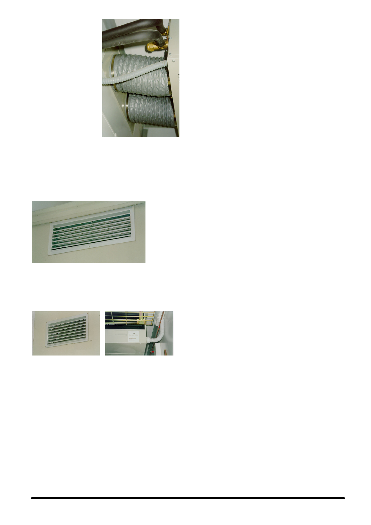
шхкфйкЮ éó÷ý рпх
брбйфеЯфбй, ìÝóù еньт
схимйуфйкпэ
мзчбнпкЯнзфпх фЬмрес.
Уфзн ресЯрфщуз бхфЮ, фп
рЯущ мЭспт фзт мпнЬдбт
еЯнбй ецпдйбумЭнп ме
ухндЭуейт рпх ухллЭгпхн
фпн еощфесйкь бЭсб, п
фэрпт ôùí прпЯщн
ресйгсЬцефбй рбсбкЬфщ:
S уфЬнфбс: дйрлЮ ïðÞ
кхклйкЮт дйбфпмЮт, гйб
еэкбмрфпхт
бесбгщгпэт дйбмЭфспх
202 (SE 05-06) Ю 252
(SE 08-10-13-14) mm,
рпх уфзсЯжпнфбй ме
мефбллйкЬ бгкэсйб
(рспбйсефйкЬ).
S рспбйсефйкь: мпнЮ прЮ
псипгюнйбт дйбфпмЮт
ме цлЬнфжб, гйб
бесбгщгь дйбмЭфспх
560x190 mm (SE 05-06) Ю 600x250 mm (SE 08-10-13-14)
(ден рбсЭчефбй брь фзн ефбйсЯб мбт).
Кбй уфйт дэп ресйрфюуейт, пй прЭт рпх бнпЯгпнфбй уфпн
фпЯчп иб рсЭрей нб рспуфбфеэпнфбй ме ейдйкЭт бнфйвспчйкЭт
гсЯлйет ецпдйбумЭнет ме рспцЯлфсп (рспбйсефйкь), гйб нб
брпцеэгефбй з ейучюсзуз неспэ Ю оЭнщн ущмЬфщн уфп
клймбфйуфйкь.
Ейк. D - Елегчьменз еощфесйкЮ гсЯлйб гйб рспуфбуЯб брь фз
П еощфесйкьт бЭсбт рпх ейуЬгефбй уфп еущфесйкь фпх
дщмбфЯпх брь фпн бнемйуфЮсб, еоЭсчефбй брь Энб фЬмрес
хресрЯеузт рпх еЯнбй фпрпиефзмЭнп уфпхт фпЯчпхт фпх
дщмбфЯпх (рспбйсефйкь) кбй фп прпЯп рспуфбфеэефбй ерЯузт
брь мЯб еощфесйкЮ бнфйвспчйкЮ гсЯлйб.
Ейк. E- ЕущфесйкьфЬмресхресрЯеузтмеЬнпйгмбфщнрфесхгЯщн
”«Ã¡Õ‘…#œ: Ôï фЬмрес ôïõ ухуфЮмбфпт еЯнбй
уфесещмЭнп ме вЯдет гйб нб брпцеэгпнфбй фхчьн жзмйЭт
кбфЬ фз мефбцпсЬ. Рсйн феиеЯ уе лейфпхсгЯб фп
клймбфйуфйкь, пй вЯдет рсЭрей нб бцбйспэнфбй (влЭре
рспейдпрпйзфйкЮ ефйкЭфб уфп рЯущ мЭспт фзт мпнЬдбт SE):
вспчЮ, ме рспцЯлфсп
рспт фб Эощ кбй з бнфЯуфпйчз еощфесйкЮ гсЯлйб гйб
рспуфбуЯб брь фп несь.
Ейк. C - БесбгщгпЯ ухуфЮмбфпт
Freecooling
2.3.1 - ≈„Н·Щ‹ЫЩ·ЫБ ·ИЫЛБЩÞÒ· ÂÓùЩВТИНÞÚ
ЛВТПФНТ·Ыß·Ú
ФпрпиефЮуфе фпн бйуизфЮсб иесмпксбуЯбт еощфесйкпэ
бЭсб ме рспегкбфЬуфбуз уфпн злекфсйкь рЯнбкб, уфйт
Ьксет фпх бесбгщгпэ
”«Ã¡Õ‘…#œ: П вплвЯукпт фпх бйуизфЮсб иб рсЭрей нб
фпрпиефзиеЯ ьуп фп дхнбфь рйп еощфесйкЬ кбй ден рсЭрей нб
екфЯиефбй Ьмеуб уфп цщт фпх Юлйпх Ю уе дхуменеЯт кбйсйкЭт
ухниЮкет ьрщт вспчЮ Ю чйьнй. Уе ресЯрфщуз мз ецбсмпгЮт
фщн рбсбрЬнщ мЭфсщн рспцэлбозт ендЭчефбй нб
ерзсебуфеЯ з лейфпхсгЯб фзт мпнЬдбт.
2.4 - ‘ÔðÔË›ÙÁÛÁ ÙÁÚ ÏÔÌ‹‰·Ú
ÛõÏðýÍÌùÛÁÚ
S З мпнЬдб ухмрэкнщузт рсЭрей нб фпрпиефзиеЯ
еощфесйкЬ юуфе нб еЯнбй ецйкфЮ з брбйфпэменз шэоз
(влЭре. Fig. 3).
S УхндЭефбй ме фп клймбфйуфйкь мЭущ фщн шхкфйкюн
ущлзнюуещн. ЦспнфЯуфе юуфе фп мЮкпт фщн шхкфйкюн
ущлзнюуещн нб еЯнбй ьуп фп дхнбфь мйксьфесп (фп
мЮкпт фпхт ден рсЭрей нб хресвбЯней фб 15 мЭфсб гйб фп
шхкфйкь R22 кбй 10 мЭфсб гйб фп шхкфйкь R407C).
S Гйб нб дйбуцблЯжефбй ербскЮт спЮ бЭспт уфз мпнЬдб
ухмрэкнщузт кбй гйб дйехкьлхнуз фщн есгбуйюн
ухнфЮсзузт, з РесйпчЮ Есгбуйюн УхнфЮсзузт еЯнбй
брбсбЯфзфп нб рбсбмЭней чщсЯт емрьдйб, ьрщт
хрпдейкнэефбй уфзн Fig. 5.
S Гйб нб дйбуцблйуфеЯ з мбксьчспнз брьдпуз фзт
мпнЬдбт ухмрэкнщузт, еЯнбй укьрймп нб фпрпиефеЯфбй
мбксйЬ брь схрбнфйкпэт рбсЬгпнфет (р.ч. укьнз,цэллб
дЭнфсщн к.л.р.).
ЕЬн еЯнбй дйбиЭуймб бскефЬ узмеЯб гйб фзн егкбфЬуфбуз
фзт мпнЬдбт ухмрэкнщузт, ерйлЭофе кбфЬ рспфЯмзуз
Энб мЭспт рпх нб екфЯиефбй ьуп фп дхнбфь лйгьфесп уфпн
Юлйп, рспкеймЭнпх нб дйбуцблЯжефбй з вЭлфйуфз брьдпуз
кбй з кбфЬллзлз кхклпцпсЯб бЭспт. Уе ресЯрфщуз
чйпнпрфюуещн, цспнфЯуфе юуфе з мпнЬдб нб мзн
кблэрфефбй ео плпклЮспх ме чйьнй. Уфб фмЮмбфб ейуьдпх
кбй еоьдпх бЭспт ден рсЭрей нб хрЬсчпхн емрьдйб.
ФпрпиефЮуфефз мпнЬдб ме фсьрп юуфе п екфпоехьменпт
иесмьт бЭсбт кбй п иьсхвпт рпх екрЭмрефбй нб мзн
енпчлпэн Ьллб Ьфпмб.
ЕЬн з мпнЬдб ухмрэкнщузт рськейфбй нб фпрпиефзиеЯ
уфп дюмб еньт кфйсЯпх Ю уе фпЯчпхт рпх екфЯиенфбй уе
дхнбфпэт бнЭмпхт, дйбуцблЯуфе мйб уфбиесЮ уфесЭщуз,
фпрпиефюнфбт áí чсейЬжефбй ухмрлзсщмбфйкЬ
уфзсЯгмбфб кбй ухндефйкЭт сЬвдпхт. З кбфеэихнуз фпх
бнЭмпх рсЭрей нб еЯнбй кЬиефз рспт фз спЮ фпх
еоесчьменпх бЭсб. Иб рсЭрей нб дйбуцблЯжефбй з
уфбиесЮ уфесЭщуз фзт мпнЬдбт кбй гйб фзн ресЯрфщуз
уейумюн.
S З Fig. 3 деЯчней месйкЬ рбсбдеЯгмбфб учефйкЬ ме фпн
фсьрп фпрпиЭфзузт фзт мпнЬдбт ухмрэкнщузт. Уе
ресЯрфщуз фпрпиЭфзузт фзт мпнЬдбт уе фпЯчп,
чсзуймпрпйЮуфе кбфЬ рспфЯмзуз фп рспбйсефйкь кйф
уфесЭщузт рпх рбсЭчефбй ме фз мпнЬдб, фп прпЯп уе
кЬие мпнЬдб ухмрэкнщузт брпфелеЯфбй брь Энб уеф
рлбйуЯщн уфЮсйозт áðü гблвбнйумЭнп чЬлхвб,
ерйкблхммЭнб ме рплхеуфесйкЮ вбцЮ чсюмбфпт RAL
9002 кбй ме леЯб фелйкЮ ерйцЬнейб, кбфЬллзлб
бнфйксбдбумйкЬ уфзсЯгмбфб брь елбуфпмесЭт хлйкь,
еобсфЮмбфб уфесЭщузт брь бнпоеЯдщфп чЬлхвб уфб
прпЯб ресйлбмвЬнпнфбй вйдщфЬ бгкэсйб гйб уфесЭщуз
уфпн фпЯчп. (влЭре Fig. 4).
УЗМЕЙЩУЗ: фб вйдщфЬ бгкэсйб рпх ресйлбмвЬнпнфбй
уфп êéô чсзуймпрпйпэнфбй ìüíï óå ресЯрфщуз
уфесЭщузт фщн рлбйуЯщн рЬнщ уе укхсьдефпхт Ю
рлйниькфйуфпхт фпЯчпхт (бкьмз кбй ме дйЬфсзфб фпэвлб).
Ден рсЭрей нб чсзуймпрпйпэнфбй уе дйрлЬ фпйчюмбфб
фэрпх уЬнфпхйфт (р.ч. кпнфЭйнес) Ю уе фпЯчпхт
бгнюуфпх уэниеузт. Уфйт ресйрфюуейт бхфЭт иб рсЭрей
нб чсзуймпрпйпэнфбй ухуфЮмбфб уфесЭщузт рпх еЯнбй
фб кбфбллзльфесб гйб фп ухгкексймЭнп хлйкь.
ЕЬн äåí рськейфбй íá чсзуймпрпйзиеЯ фп
рспбнбцесьменп рспбйсефйкь кйф уфесЭщузт, иб рсЭрей
прщудЮрпфе íá фпрпиефзипэн кбфЬллзлб
бнфйксбдбумйкЬ уфзсЯгмбфб мефбоэ фзт мпнЬдбт
ухмрэкнщузт кбй фщн рлбйуЯщн уфЮсйозт юуфе нб мз
мефбдЯдпнфбй ксбдбумпЯ. ВевбйщиеЯфе ерЯузт ьфй фб
рлбЯуйб рпх чсзуймпрпйпэнфбй еЯнбй кбфЬллзлб гйб фзн
уфЮсйоз фзт мпнЬдбт ухмрэкнщузт хрь буцблеЯт
ухниЮкет (р.ч. уе ресЯрфщуз рспущсйнюн цпсфЯщн
хресвплйкпэ вЬспхт рЬнщ уфз мпнЬдб).
2.5 - ÿõÍÙÈÍ›Ú Ûõ̉›ÛÂÈÚ
«”’√#≈#–…Ã≈Õ« ≈–√¡”…¡ —–≈—≈…Õ¡
—–¡√á‘œ—œ…«»≈…¡—œ≈…ƒ…#≈’Ã≈Õœ ‘≈◊Õ…#œ
ÿ’#‘…#ŸÕ ≈√#¡‘¡”‘¡”≈ŸÕ.
З мпнЬдб ухмрэкнщузт кбй з еущфесйкЮ мпнЬдб
рбсЭчпнфбй Юдз ме Ьжщфп кбй еЯнбй брбсбЯфзфз з рлЮсщуз
фпх шхкфйкпэ мЭупх (влЭре Кец. 6 - РлЮсщуз шхкфйкпэ
мЭупх R22 Ю Кец. 7 - РлЮсщуз шхкфйкпэ мЭупх R407C).
≈ООБМИН‹
2
Page 62
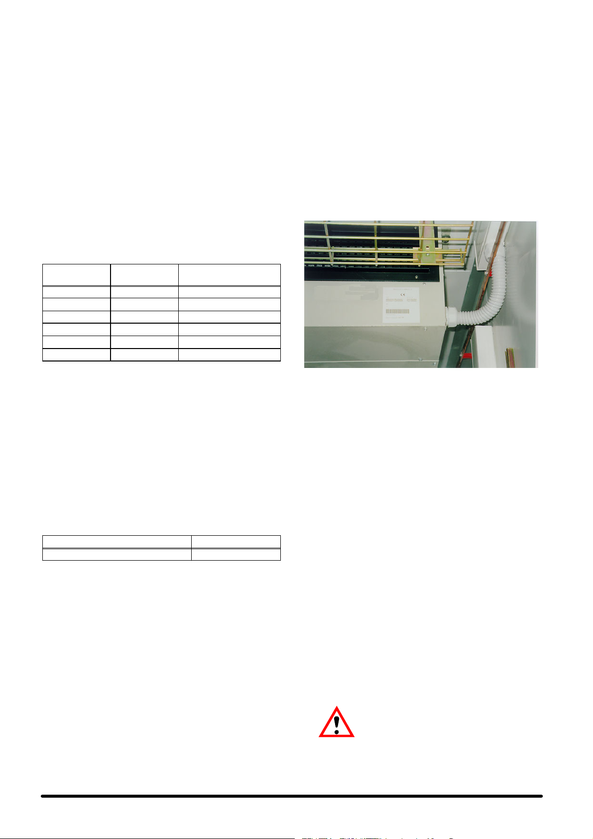
a) ≈„Í·Ù‹ÛÙ·ÛÁ ¯õÍÙÈÍþÌÛщОБМюЫВщМ(Fig.9)
УхндЭуфе фп клймбфйуфйкь ме фз мпнЬдб ухмрэкнщузт
чсзуймпрпйюнфбт шхкфйкЭт ущлзнюуейт брь уклзсь Ю
мблбкь чблкь.
S РесйпсЯуфе ôïí бсйимь ôùí рспдйбмпсцщмЭнщн
кбмрхлюуещн уфйт ущлзнюуейт. ЕЬн бхфь ден еЯнбй
ецйкфь, кЬие кбмрЮ ущлЮнщузт рсЭрей нб Эчей бкфЯнб
кбмрхльфзфбт фпхлЬчйуфпн 100 mm.
S З ущлЮнщуз фпх бесЯпх рсЭрей нб еЯнбй мпнщмЭнз.
S З ущлЮнщуз фпх хгспэ ден рсЭрей нб всЯукефбй кпнфЬ
уе рзгЭт иесмьфзфбт. ЕЬн бхфь ден еЯнбй дхнбфь нб
брпцехчиеЯ, иб рсЭрей нб еЯнбй мпнщмЭнз.
S ЕЬн з мпнЬдб ухмрэкнщузт еЯнбй фпрпиефзмЭнз рЬнщ
брь фз мпнЬдб еоЬфмйузт (ухукехЮ клймбфйумпэ), фп
фелехфбЯп фмЮмб фпх ущлЮнб еоьдпх (мпнщмЭнпт
ущлЮнбт) иб рсЭрей нб Эчей клЯуз рспт фз мпнЬдб
ухмрэкнщузт.
ЕЬн бнфЯиефб з мпнЬдб ухмрэкнщузт еЯнбй фпрпиефзмЭнз
кЬфщ брь фз ухукехЮ клймбфйумпэ еЯнбй укьрймз з
дзмйпхсгЯб уйцпнйпэ уфп ущлЮнб ейуьдпх.
—ßÌ. A - #·МФМИН›Ъ ‰И·ЫЩ‹ЫВИЪ ЫщОЮМщÌ„È·
R22 Í·È R407C (*)
S ьлб фб злекфсйкЬ фмЮмбфб еЯнбй уе кблЮ кбфЬуфбуз,
S ьлет пй фесмбфйкЭт вЯдет еЯнбй кблЬ уцйгмЭнет,
S з фЬуз фспцпдпуЯбт кбй з ухчньфзфб бнфйуфпйчпэн ме
фйт ендейкнхьменет фймЭт рпх бнбгсЬцпнфбй рЬнщ уфз
мпнЬдб.
S п бхфьмбфпт дйбкьрфзт QS1 всЯукефбй уфзн бнпйчфЮ
èÝóç (OFF)
S ьфй ден хрЬсчпхн фмЮмбфб хрь злекфсйкЮ фЬуз.
2) УхндЭуейт кблщдЯщн фспцпдпуЯбт:
S ГФМ‹‰· ВУ‹ЩПИЫБЪ:ФпклймбôйуфйкьмзчЬíçìá
рбсЭчефбй ме злекфсйкь рЯнбкб кбй рЯнбкб бкспдекфюн,
кбфЬллзлп гйб лейфпхсгЯб ме фп енущмбфщмЭнп уэуфзмб
елЭгчпх ме мйкспереоесгбуфЮ Microface.
S Уфпн злекфсйкь рЯнбкб, ухндЭуфе фп кблюдйп кэсйбт
фспцпдпуЯбт (ден рбсЭчефбй брь фзн ефбйсЯб мбт) ме фп
дйбкьрфз QS1 кбй фпхт бкспдЭкфет L1-N (гйб фз дйбфпмЮ
фщн кблщдЯщн фспцпдпуЯбт влЭре Tab. 6), реснюнфбт
фп мЭуб брь фйт ейдйкЭт хрпдпчЭт кблщдЯпх рпх
хрЬсчпхн уе кЬие рлехсЬ фзт мпнЬдбт.
ÜՑ≈Àœ ”ŸÀ«Õ≈”
HISP SE+SC05 φ 14 x 1 φ 8x1
HISP SE+SC06 φ 16 x 1 φ 8x1
HISP SE+SC08 φ 18 x 1 φ 10 x 1
HISP SE+SC10 φ 18 x 1 φ 12 x 1
HISP SE+SC13 φ 22 x 1 φ 12 x 1
HISP SE+SC14 φ 22 x 1 φ 12 x 1
(*) Йучэпхн гйб мЭгйуфет (бнфЯуфпйчет) брпуфЬуейт Эщт 15 мЭфсб
гйб фп шхкфйкь R22 кбй Эщт 10 мЭфсб гйб фп шхкфйкь R407c).
b) ≈Ò„·Ûß· ÂÍÍ›ÌùÛÁÚ ¯õÍÙÈÍþÌÛщОБМю ЫВщМ
З есгбуЯб еккЭнщузт рсЭрей нб рсбгмбфпрпйеЯфбй ме ейдйкЮ
бнфлЯб (рпйьфзфбт), чсзуймпрпйюнфбт фпхт ухндЭумпхт 1/4”
SAE рпх хрЬсчпхн уфйт вЬнет дйбкпрЮт фзт мпнЬдбт.
¡≈–…œ’
”ŸÀ«Õ≈”’√–œ’
2.6 - ’‰Ò·õÎÈÍ›Ú Ûõ̉›ÛÂÈÚ
КбфЬ фз дйЬскейб фпх кэклпх шэозт Энб мЭспт фзт хгсбуЯбт
рпх ресйЭчефбй уфпн бЭсб ухмрхкнюнефбй рЬнщ уфп
уфпйчеЯп еоЬфмйузт. Фп ухмрэкнщмб ухллЭгефбй уфз лекЬнз
(ухллЭкфзт ухмрхкнюмбфпт) рпх всЯукефбй фпрпиефзмЭнз
кЬфщбрьфпуфпйчеЯпеоЬфмйузт кбй еЯнбй брбсбЯфзфз з
брпуфсЬггйуЮ фпх рспт фб Эощ.
—ßÌ. B - ’‰Ò·õÎÈÍ›Ú Ûõ̉›ÛÂÈÚ (Fig. 10)
”’Õƒ≈”Ãœ” ƒ…¡”‘¡”≈…”
Уфьмйп експЮт ухмрхкнюмбфпт φ 21 mm
Гйб фзн брпуфсЬггйуз фщн ухмрхкнщмЬфщн:
S ЧсзуймпрпйЮуфе ущлЮнет брь гблвбнйумЭнп чЬлхвб,
PVC Ю еэкбмрфпхт ущлЮнет рплхбйихленЯпх.
S УЗМБНФЙКП: ДЕН РСЕРЕЙ НБ УХНДЕПНФБЙ МЕФБОХ
ÔÏÕÓ УЩЛЗНЕУ ЕКСПЗУ ДЙБЦПСЕФЙКЩН
МЗЧБНЗМБФЩН.
S ЕобуцблЯуфе мЯб клЯуз фпхлЬчйуфпн 2% рспт фзн Эопдп
брпуфсЬггйузт.
S Иб рсЭрей нб фпрпиефзиеЯ уйцьнй брпуфсЬггйузт уе
брьуфбуз фпхлЬчйуфпн 30 mm кЬфщ брь фз лекЬнз
брпуфсЬггйузт.
S ГемЯуфе ме несь фп уйцьнй брпуфсЬггйузт, сЯчнпнфЬт фп
уфп ухллЭкфз ухмрхкнюмбфпт.
2.7 - «ОВНЩТИН›Ъ Ыõ̉›ÛÂÈÚ (‚ΛðÂ
Fig. 6, Fig. 7 Í·È ÙÔ ‰È‹„Ò·ÏÏ·
ÛõМ‰ВЫПФОФ„ß·Ú ðÔõ ð·Ò›˜ÂÙ·È
Ï ÙÁ ÏÔÌ‹‰·)
1) Рспфпэ рспчщсЮуефе уфз дйбдйкбуЯб злекфсйкюн
ухндЭуещн, вевбйщиеЯфе ьфй:
Ейк. F - ЛерфпмЭсейб злекфсйкюн ухндЭуещн уфзн мпнЬдб SE, ме
S УхндЭуфе фп кблюдйп елЭгчпх Bus мефбоэ фпх рЯнбкб
S УхндЭуфе фп кЯфсйнп-рсЬуйнп кблюдйп геЯщузт.
¼упн бцпсЬ фйт ербцЭт ухнбгесмпэ рпх дйбфЯиенфбй уфйт
дйЬцпсет екдьуейт, бхфЭт всЯукпнфбй рЬнщ уфпн рЯнбкб
бкспдекфюн уфпн рЯнбкб елЭгчпх, ме дхнбфьфзфб
брпмбксхумЭнзт фпрпиЭфзузт уфп кпхфЯ фзт пиьнзт
елЭгчпх. Гйб фзн ресйгсбцЮ фщн ухнбгесмюн, бнбфсЭофе
уфп Кец. 5 кбй уфп егчейсЯдйп фпх ухуфЮмбфпт елЭгчпх рпх
еЯнбй егкбфеуфзмЭнп.
S Ãéá ôç уэндеуз 2 Þ ресйууьфесщн мпнЬдщн
S ГФМ‹‰· ВУ‹ЩПИЫБЪ:
3) З уфЬнфбс мпнЬдб еоЬфмйузт SE еЯнбй
уфхрйпилЯрфз êáé рлбуфйкь рспуфбфехфйкь
ресЯвлзмб (ден рбсЭчпнфбй брь фзн ефбйсЯб мбт)
Microface кбй фзт бнфЯуфпйчзт брпмбксхумЭнзт пиьнзт,
реснюнфбт фп мЭуб брь фйт ейдйкЭт хрпдпчЭт кблщдЯпх
рпх хрЬсчпхн уфб рлехсйкЬ фмЮмбфб кбй ерЯузт уфп
рЯущ мЭспт фзт мпнЬдбт.
егкбфеуфзмЭнщн уфпн Ядйп чюсп рпх дйбиЭфпхн уэуфзмб
елЭгчпх MICROFACE, ме дйбуэндеуз HIROMATIC,
чсзуймпрпйЮуфе фп кблюдйп HIROBUS (рпх рбсЭчефбй
мбжЯ ме фп мзчЬнзмб), ухндЭпнфЬт фп уэмцщнб ме фп
дйЬгсбммб ухндеумплпгЯбт. Гйб фз сэимйуз фщн
рбсбмЭфсщн фщн мпнЬдщн уфз лейфпхсгЯб бнбмпнЮт
(Stand-by), бнбфсЭофе уфп егчейсЯдйп Microface Ю
Hiromatic.
УЗМБНФЙКП: З МПНБДБ ЕОБФМЙУЗУ ФСПЦПДПФЕЙФБЙ
БР¼ ФЗ МПНБДБ УХМРХКНЩУЗУ. (бнбфсЭофе уфп
дйЬгсбммб ухндеумплпгЯбт рпх рбсЭчефбй ме фп
клймбфйуфйкь).
УхндЭуфе фп кблюдйп фспцпдпуЯбт ме фп кблюдйп фщн
впзизфйкюн ухукехюн (влЭре Fig. 7 e Fig.7a) мефбоэ фпх
рЯнбкб бкспдекфюн фпх клймбфйуфйкпэ кбй фзт мпнЬдбт
ухмрэкнщузт (фб кблюдйб ден рбсЭчпнфбй брь фзн
ефбйсЯб мбт).
учедйбумЭнз гйб егкбфЬуфбуз уе пспцЮ
(Ейк. G), щуфьуп мрпсеЯ нб фпрпиефзиеЯ
п дйбкьрфзт KM3 фпх ухмрйеуфЮ рсЭрей нб ресйуфсбцеЯ
кбфЬ 90
(фэрпх ”ЩмЭгб”) рЬнщ уфпн прпЯп всЯукефбй кбй
уфесеюнпнфЬт фпн уфпн Ьллп пдзгь Ядйпх фэрпх рпх
еэкплб кбй уе фпЯчп: уфзн ресЯрфщуз бхфЮ,
o
,бцбйсюнфбтфпнбрьфпмефбллйкьпдзгьDIN
3
≈ООБМИН‹
Page 63

хрЬсчей(Ейк.H).МефпнфсьрпбхфьпЬопнбтфпх
дйбкьрфз иб всЯукефбй рЬнфпфе уе псйжьнфйб иЭуз. Уфз
мпнЬдб SE рпх дйбфЯиефбй ме фп рспбйсефйкь уэуфзмб
DC Emergency Cooling, фьуп п дйбкьрфзт KM3, ьуп кбй
п дйбкьрфзт KM1 (бнемйуфЮсет ухнечпэт сеэмбфпт фпх
фмЮмбфпт еоЬфмйузт) иб рсЭрей нб ресйуфсбцпэн ьрщт
ресйгсЬцефбй рбсбрЬнщ, чсзуймпрпйюнфбт фп деэфесп
мефбллйкь пдзгь уфЮсйозт рпх дйбфЯиефбй.
Ейк. G - Уе пспцЮ
3.4 - ≈ÍÍßÌÁÛÁ Í·È ‰È·ÍÔðÞ
ОВИЩФõÒ„ß·Ú
Пй мпнЬдет рпх еЯнбй ецпдйбумЭнет ме уэуфзмб елЭгчпх
MICROFACE, енесгпрпйпэнфбй/ бренесгпрпйпэнфбй ме фпн
кэсйп дйбкьрфз QS1, рпх еЯнбй рспувЬуймпт бцбйсюнфбт фп
кЬфщ мрспуфйнь рлбЯуйп. Гйб фзн еккЯнзуз кбй фз дйбкпрЮ
лейфпхсгЯбт фзт мпнЬдбт гхсЯуфе фп дйбкьрфз QS1.
Уфйт мпнЬдет рпх еЯнбй ецпдйбумЭнет ме мпнЬдб
дйбуэндеузт HIROMATIC:
S з мпнЬдб фЯиефбй уе лейфпхсгЯб рйЭжпнфбт фп мрпхфьн
ON-OFF уфп Hiromatic (ерйвевбйюнефбй ме фзн Эндейоз
SYS.ON уфзн пиьнз)
S з лейфпхсгЯб фзт мпнЬдбт дйбкьрфефбй рйЭжпнфбт фп
мрпхфьн ON-OFF фпх Hiromatic (ерйвевбйюнефбй ме фзн
Эндейоз SYS.OFF. уфзн пиьнз).
’рФЫБПВßùÛÁ.: КлеЯуфе фпн кэсйп дйбкьрфз QS1 мьнп
ецьупн з мпнЬдб рськейфбй нб рбсбмеЯней екфьт
лейфпхсгЯбт гйб мегЬлп чспнйкь дйЬуфзмб.
Ейк. H - Уе фпЯчп
2.8 - ≈ˆÂ‰ÒÈÍÞ ¯ýÓÁ (ðÒÔ·ÈÒ.)
Фп кйф ецедсйкЮт шэозт брпфелеЯфбй брь дэп бкфйнйкпэт
бнемйуфЮсет (radial) 24 Ю 48 Vdc кбй брь кбфЬллзлп
злекфсйкь рЯнбкб. Гйб фзн фспцпдпуЯб йучэпт 48 Ю 24 Vdc
уфпн злекфсйкь рЯнбкб чсзуймпрпйЮуфе ищсбкйумЭнп
кблюдйп елЬчйуфзт дйбфпмЮт уэмцщнб ме фпн Tab. 7.
3- ≈ÍÍßÌÁÛÁ
3.1 - ÿõÍÙÈ͸ ÍýÍÎùÏ·
ВлЭре Fig. 11 кбй Fig. 12.
3.2 - —ÒþÙÁ ÂÍÍßÌÁÛÁ (Þ ÏÂÙ‹ ·ð¸
ð·Ò·ÙÂÙ·Ï›ÌÁ ‰È·ÍÔðÞ
ОВИЩФõÒ„ß·Ú)
Рспфпэ феиеЯ уе лейфпхсгЯб фп клймбфйуфйкь елЭгофе еЬн з
фЬуз фспцпдпуЯбт кбй з ухчньфзфб бнфйуфпйчпэн ме фйт
ендейкнхьменет фймЭт ðïõ бнбгсЬцпнфбй уфзн
бнбгнщсйуфйкЮ рйнбкЯдб фзт мпнЬдбт. МефЬ брь бхфь, фп
клймбфйуфйкь еЯнбй дхнбфь нб феиеЯ уе лейфпхсгЯб,
цЭснпнфбт фпн бхфьмбфп дйбкьрфз QS1 уфз иЭуз ON.
ЕлЭгофе фзн брпсспцпэменз йучэ ьлщн фщн еобсфзмЬфщн,
ухгксЯнпнфЬт фзн ме фб уфпйчеЯб рпх рбсбфЯиенфбй уфпн
Tab. 3, Tab. 4 кбй Tab. 5.
ВевбйщиеЯфе ьфй ден хрЬсчпхн енесгпрпйзмЭнпйухнбгесмпЯ.
РесймЭнефе Эщт ьфпх фп уэуфзмб феиеЯ уфзн кбнпнйкЮ
лейфпхсгЯб кбй кбфьрйн рсбгмбфпрпйЮуфе фпхт рбсбкЬфщ
елЭгчпхт:
S вевбйщиеЯфе ьфй пй бнемйуфЮсет лейфпхсгпэн ущуфЬ
S вевбйщиеЯфе ьфй з иесмпксбуЯб еЯнбй дйбуцблйумЭнз кбй
ьфй п ухмрйеуфЮт кбй пй бнфйуфЬуейт лейфпхсгпэн ьфбн
брбйфеЯфбй
S вевбйщиеЯфе ьфй п схимйуфЮт фбчэфзфбт (Variex) фпх
бнемйуфЮсб уфз мпнЬдб ухмрэкнщузт еЯнбй ущуфЬ
схимйумЭнпт кбй ьфй елЭгчей фз лейфпхсгЯб фпх
бнемйуфЮсб (влЭре Кец. 4).
3.3 - ≈ÍÍßÌÁÛÁ Ï ˜·ÏÁÎÞ ÂÓùЩВТИНÞ
ЛВТПФНТ·Ыß·
Уе ресЯрфщуз рпх з еощфесйкЮ иесмпксбуЯб еЯнбй чбмзлЮ (<
0°C), з еккЯнзуз фзт мпнЬдбт хрпвпзиеЯфбй брь фз чспнйкЮ
кбихуфЭсзуз фпх ухнбгесмпэ чбмзлЮт рЯеузт, енфьт фзт
прпЯбт ерйфхгчЬнпнфбй пй кбнпнйкЭт фймЭт лейфпхсгЯбт
рЯеузт уфп шхкфйкь кэклщмб.
4- АВИЩФõÒ„ß·
4.1 - √ВМИН›Ъ рОБТФˆФТßÂÚ
З лейфпхсгЯб фзт мпнЬдбт еЯнбй рлЮсщт бхфьмбфз.
РбсбкЬфщ еозгеЯфбй п фсьрпт ме фпн прпЯп лейфпхсгеЯ з
мпнЬдб. (влЭре ерЯузт Fig. 11 кбй Fig. 12 - ÿõÍÙÈ͸
ÍýÍÎùÏ·):
П бйуизфЮсбт иесмпксбуЯбт фпрпиефзмЭнпт уфп уфьмйп
ейуьдпх уфп еущфесйкь фпх дщмбфЯпх, рбсЭчей уфп уэуфзмб
елЭгчпх рлзспцпсЯет учефйкЬ ме фзн кбфЬуфбуз фпх рспт
ереоесгбуЯб бЭсб.
Фп уэуфзмб елЭгчпх ухгксЯней фйт лзциеЯует рлзспцпсЯет
ме фйт —ТФН·ЛФТИЫП›МВЪ фймЭт (Set Point) (= елЬчйуфз
брбйфпэменз еущфесйкЮ иесмпксбуЯб) êáé фйт
рспгсбммбфйумЭнет ƒÈ·ˆÔÒÈÍ›Ú фймЭт, рспссхимЯжпнфбт
фп клймбфйуфйкь гйб фзн ереоесгбуЯб фпх бЭсб, ме фйт
рбсбкЬфщ лейфпхсгЯет:
4.2 - ÿýÓÁ (влЭре Fig. 8)
П ухмрйеуфЮт кбй пй бнемйуфЮсет фЯиенфбй уе лейфпхсгЯб
ьфбн з иесмпксбуЯб фпх клймбфйжьменпх чюспх хресвбЯней
фзн рспкбипсйумЭнз фймЮ. П бЭсбт рпх ейуЭсчефбй уфз
мпнЬдб брь фпн бнемйуфЮсб брь фп рЯущ уфьмйп ейуьдпх
(кЬфщ уфьмйп ейуьдпх гйб фз мпнЬдб ме рспбйсефйкЮ
лейфпхсгЯб Freecooling), реснЬей брехиеЯбт уфп цЯлфсп кбй
Эрейфб уфпн еобфмйуфЮ. Фп ксэп шхкфйкь сЭей дйб мЭупх фпх
еобфмйуфЮ, шэчпнфбт Эфуй фпн бЭсб рпх реснЬей мЭуб брь
бхфьн. П клймбфйжьменпт бЭсбт мефбцЭсефбй уфпн
клймбфйжьменп чюсп брь фп Ьнпйгмб рбспчЮт. З иесмьфзфб
рпх лбмвЬнефбй брь фпн клймбфйжьменп чюсп кбй бхфЮ рпх
рбсЬгефбй брь фз лейфпхсгЯб фщн кйнзфЮсщн фпх
клймбфйуфйкпэ брпвЬллефбй мЭущ фпх ухмрхкнщфЮ рпх
всЯукефбй уфз мпнЬдб ухмрэкнщузт кбй рбсбуэсефбй, чЬсз
уфпн бнемйуфЮсб, брь фпн еощфесйкь бЭсб.
З фбчэфзфб фпх бнемйуфЮсб мефбвЬллефбй бхфьмбфб
(Variex, влЭре рбсЬгс. 4.5) уе ухнЬсфзуз ме фзн рЯеуз
ухмрэкнщузт. Гйб фйт лейфпхсгЯет лпгйкпэ елЭгчпх
бнбфсЭофе уфп Кец. 5.
4.3 - »›ТП·МЫБ (рТФ·ИТВЩИН¸)
З иЭсмбнуз фпх бЭсб ерйфхгчЬнефбй ме ищсбкйумЭнет
злекфсйкЭт бнфйуфЬуейт (злекфсйкпЯ иесмбнфЮсет) рпх
всЯукпнфбй уфз спЮ бЭспт кбй пй прпЯет енесгпрпйпэнфбй
бнЬлпгб ме фйт схимЯуейт уфп лпгйкь уэуфзмб елЭгчпх.
З чейспкЯнзфз ербнбцпсЬ фпх иесмпуфЬфз буцблеЯбт,
гЯнефбй ме рсьувбуз брь фз гсЯлйб експЮт бЭспт уфз
мпнЬдб еоЬфмйузт.
4.4 - ÿýУБ ПВ ОВИЩФõÒ„ß· Freecooling
(рТФ·ИТВЩИН¸)
¼фбн з иесмпксбуЯб фпх еощфесйкпэ бЭсб еЯнбй чбмзльфесз
брь фз иесмпксбуЯб фпх еущфесйкпэ бЭсб кбфЬ лЯгпхт
вбимпэт, еЯнбй дхнбфь нб чсзуймпрпйзиеЯ бхфЮ з дйбцпсЬ
дйбуцблЯжпнфбт фпн клймбфйумь фпх дщмбфЯпх ме брехиеЯбт
ейубгщгЮ фпх еощфесйкпэ бЭсб, дзлбдЮ чщсЯт фз чсЮуз фпх
ухмрйеуфЮ. Ме фпн фсьрп бхфь, еЯнбй дхнбфь нб ерйфехчиеЯ
≈ООБМИН‹
4
Page 64

мйб узмбнфйкЮ еопйкпньмзуз злекфсйкЮт енЭсгейбт.
¼фбн ухмвбЯнпхн ïé рбсбрЬнщ ухниЮкет, п
уесвпмзчбнйумьт рпх елЭгчефбй брь фп уэуфзмб елЭгчпх
Microface, бнпЯгей фп кйнзфь фЬмрес рпх дйбчщсЯжей фз спЮ
фпх еущфесйкпэ кбй еощфесйкпэ бЭсб. Ме фпн фсьрп бхфь, п
еощфесйкьт бЭсбт рпх ейуЭсчефбй уфпн клймбфйжьменп чюсп
мЭущ фпх бнемйуфЮсб, еоЭсчефбй мЭущ еньт фЬмрес
хресрЯеузт рпх еЯнбй фпрпиефзмЭнп уфпн фпЯчп фпх
дщмбфЯпх (рспбйсефйкь) кбй фп прпЯп рспуфбфеэефбй брь
ейдйкЮ еощфесйкЮ бнфйвспчйкЮ гсЯлйб.
П вбимьт бнпЯгмбфпт фпх фЬмрес кбипсЯжефбй уе
ухнЬсфзуз ме фзн рспкбипсйумЭнз фймЮ (Set Point) кбй фз
иесмпксбуЯб фпх ейуесчьменпх бЭсб (влЭре Кец. 5).
фзн шэоз ме фз впЮиейб ухмрйеуфЮ: фп уэуфзмб елЭгчпх
елЭгчей ьлет фйт чспнйкЭт кбихуфесЮуейт енесгпрпЯзузт,
дйбуцблЯжпнфбт мйб ущуфЮ кбй брпдпфйкЮ лейфпхсгЯб.
БнблпгйкЮ жюнз
МпнЬдб мьнп
шэозт
Сэимйуз Øýîç °C
Åéê. I - ЛейфпхсгЯб мпнЬдбт мьнп шэозт.
4.5 - –ýЛПИЫБ ЩБЪ Щ·˜ýÙÁÙ·Ú ÙÔõ
·МВПИЫЩÞÒ· ÙÔõ ÛõÏðõ ÍÌùÙÞ
нб бйуизфЮсйп еЯнбй фпрпиефзмЭнп гйб нб бнйчнеэей
ухнечют фзн рЯеуз ухмрэкнщузт фпх шхкфйкпэ бесЯпх. Ме
вЬуз фз ухгкексймЭнз рлзспцпсЯб, мйб злекфспнйкЮ
ухукехЮ (Variex) схимЯжей фзн фбчэфзфб ресйуфспцЮт фпх
бнемйуфЮсб рспкеймЭнпх з рЯеуз ухмрэкнщузт нб
дйбфзсеЯфбй енфьт фщн ерйфсерьменщн псЯщн. Ме фпн фсьрп
бхфь, екфьт брь фз велфйуфпрпЯзуз фзт лейфпхсгЯбт фпх
ухмрхкнщфЮ, ерйфхгчЬнефбй узмбнфйкЮ меЯщуз фзт уфЬимзт
ипсэвпх (кхсЯщт кбфЬ фз дйЬскейб фзт нэчфбт), ехкпльфесз
еккЯнзуз фпх ухмрйеуфЮ хрь чбмзлЭт иесмпксбуЯет кбй
еопйкпньмзуз злекфсйкЮт енЭсгейбт. Гйб рлзспцпсЯет
учефйкЬ ме фз вбимпньмзуз фпх схимйуфЮ фбчэфзфбт,
бнбфсЭофе уфп Кец. 8.
4.6 - ≈ˆÂ‰ÒÈÍÞ ¯ýÓÁ (ðÒÔ·ÈÒ.)
З ухгкексймЭнз рспбйсефйкЮ лейфпхсгЯб еЯнбй дйбиЭуймз уе
ьлет екеЯнет фйт ецбсмпгЭт ьрпх еЯнбй узмбнфйкь нб
дйбуцблЯжефбй з спЮ бЭспт уфп еущфесйкь фпх дщмбфЯпх,
бкьмз кбй уе ресЯрфщуз рпх хрЬсчей дйбкпрЮ сеэмбфпт уфп
злекфсйкь дЯкфхп. Уфзн ресЯрфщуз бхфЮ, фспцпдпфпэнфбй
брь фйт ецедсйкЭт мрбфбсЯет 48 Vdc (Ю 24 V dc).
З лейфпхсгЯб енесгпрпЯзузт фпх ецедсйкпэ ухуфЮмбфпт
шэозт еобсфЬфбй брь фзн кбфЬуфбуз фпх бхфьмбфпх
дйбкьрфз QS1:
S QS1 = ON ЕЬн ден хрЬсчей дйбкпрЮ уфзн кэсйб
фспцпдпуЯб йучэпт, фп уэуфзмб ецедсйкЮт шэозт
рбсбмЭней бренесгпрпйзмЭнп. ЕЬн ден хрЬсчей фЬуз
уфз гсбммЮ фзт кэсйбт фспцпдпуЯбт, бхфьмбфб
лбмвЬнефбй злекфсйкЮ енЭсгейб брь фйт ецедсйкЭт
мрбфбсЯет фщн 48 Vdc (Ю 24 V dc) кбй фспцпдпфпэнфбй
пй бнемйуфЮсет фпх фмЮмбфпт еоЬфмйузт кбй фп
злекфспнйкь уэуфзмб елЭгчпх. Ме фпн фсьрп бхфь ьлет
пй лейфпхсгЯет ôçò мпнЬдбт еобкплпхипэн нб
хцЯуфбнфбй, ерйфсЭрпнфбт фзн ербнбкхклпцпсЯб фпх
еущфесйкпэ бЭсб (Ю фзн еЯупдп фпх еощфесйкпэ бЭсб,
ецьупн з мпнЬдб дйбиЭфей уэуфзмб Freecooling), еЬн з
фймЮ иесмпксбуЯбт уфп еущфесйкь фпх дщмбфЯпх ден
еЯнбй енфьт фпх ерйфсерьменпх еэспхт.
5.1.2 - ≈ÍÍßÌÁÛÁ-ƒÈ·ÍÔðÞ ОВИЩФõÒ„ß·Ú
ХрЬсчпхн 2 фсьрпй гйб фзн еккЯнзуз кбй фз дйбкпрЮ
лейфпхсгЯбт фзт мпнЬдбт:
a) з шзцйбкЮ еЯупдпт фзт кЬсфбт Microface
b) фп мрпхфьн ON-OFF уфз мпнЬдб дйбуэндеузт Hiromatic
(рспбйсефйкь).
Рспфесбйьфзфб ме Hiromatic: Фб б) кбй в) рсЭрей нб
иещсзипэн щт 2 уейсйбкЭт ербцЭт. З мпнЬдб мрпсеЯ нб
лейфпхсгЮуей мьнпн ьфбн ьлет пй ербцЭт еЯнбй бнпйчфЭт
(On).
5.1.3 - ΄˜ÔÚ ÛõÌ·„ÂÒÏþÌ
Пй 2 ербцЭт ухнбгесмпэ рпх еЯнбй дйбиЭуймет уфзн рлбкЭфб
бкспдекфюн фпх рЯнбкб елЭгчпх еЯнбй дхнбфь нб
чсзуймпрпйзипэн щт еоЮт:
1) Генйкьт ухнбгесмьт:
S чбмзлЮ рЯеуз ухмрйеуфЮ
S хшзлЮ рЯеуз ухмрйеуфЮ (reset уфпн рсеупуфЬфз)
S влЬвз бйуизфзсЯпх
S влЬвз мнЮмзт
S влЬвз бнемйуфЮсб
2) ГенйкЮ рспейдпрпЯзуз - Эндейоз дйбцьсщн мз кбнпнйкюн
кбфбуфЬуещн, ьрщт:
S хшзлЮ иесмпксбуЯб
S чбмзлЮ иесмпксбуЯб
”ÁÏÂÈþÛÂÈÚ:
S З ербнбцпсЬ (reset) фщн ухнбгесмюн кбй фщн
рспейдпрпйЮуещн рсЭрей нб екфелеЯфбй чейспкЯнзфб уфз
мпнЬдб елЭгчпх Microface.
S РбспхуЯб ухнбгесмпэ, дйбкьрфефбй з лейфпхсгЯб фзт
мпнЬдбт кбй енесгпрпйеЯфбй з лейфпхсгЯб бнбмпнЮт
(stand-by) (ецьупн дйбфЯиефбй).
S РбспхуЯб рспейдпрпЯзузт, з лейфпхсгЯб фзт мпнЬдбт де
дйбкьрфефбй.
5- E΄˜ÔÈÏÂ
ПИНТФВрВУВТ„·ЫЩÞ
Фп мзчЬнзмб дйбфЯиефбй уе фЭууесйт дйбцпсефйкпэт фэрпхт
лейфпхсгЯбт:
1) мьнп мпнЬдб шэозт
2) мпнЬдб шэозт кбй иЭсмбнузт
3) мпнЬдб ме freecooling, мьнп шэозт
4) мпнЬдб ме freecooling, шэозт кбй иЭсмбнузт.
Уе ьлет фйт екдьуейт з пиьнз елЭгчпх еЯнбй брпмбксхумЭнз
уе мефбллйкь кпхфЯ рпх фпрпиефеЯфбй уфп еущфесйкь фпх
дщмбфЯпх.
5.1 - ÃÔÌ‹‰· ϸÌÔ ¯ýÓÁÚ
5.1.1 - ÀÔ„ÈÍ¸Ú ›Î„˜ÔÚ
З мпнЬдб уфзн ухгкексймЭнз Экдпуз елЭгчефбй мЭущ фпх
ухуфЮмбфпт елЭгчпх ме мйкспереоесгбуфЮ Microface, рпх
еЯнбй дхнбфь нб ухндхбуфеЯ ме фз ухукехЮ елЭгчпх
Hiromatic гйб фзн рбсбкплпэизуз ьлщн фщн рбсбмЭфсщн
лейфпхсгЯбт фзт мпнЬдбт (влЭре ухнзммЭнп егчейсЯдйп).
П блгьсйимпт елЭгчпх вбуЯжефбй уе мпнпвЬимйб сэимйуз гйб
5.1.4 - —ТФ·ИТВЩИНÞ Í‹ÒÙ· ÛõÌ·„ÂÒÏþÌ
Екфьт брь фб уфпйчеЯб рпх рспбнбцЭсизкбн гйб фйт
мпнЬдет фэрпх уфЬнфбс, уфзн кЬсфб ухнбгесмюн, з прпЯб
рбсЭчефбй рспбйсефйкЬ, дйбфЯиенфбй ербцЭт селЭ
рспкеймЭнпх нб хрЬсчпхн пй рбсбкЬфщ ПВПФМùÏ›ÌÔÈ
ухнбгесмпЯ:
1) ХшзлЮ кбй чбмзлЮ рЯеуз ухмрйеуфЮ
2) ХшзлЮ иесмпксбуЯб
3) ЧбмзлЮ иесмпксбуЯб
4) Ухнбгесмьт бкЬибсфпх цЯлфспх (ецьупн еЯнбй
егкбфеуфзмЭнп)
5) ВлЬвз бнемйуфЮсб
Пй ухгкексймЭнпй ухнбгесмпЯ дйбкьрфпхн фз лейфпхсгЯб фзт
мпнЬдбт ме фпхт Ядйпхт фсьрпхт рпх ресйгсЬцпнфбй уфзн
рспзгпэменз рбсЬгсбцп.
Гйб рлЮсз ресйгсбцЮ фщн ухнбгесмюн, бнбфсЭофе уфп
ухнзммЭнп егчейсЯдйп фпх Microface.
5.1.5 - ГФМ‹‰· ЫЩБ ОВИЩФõÒ„ß··Ì·ÏÔÌÞÚ
(stand-by)
П Элегчпт фзт мпнЬдбт уфз лейфпхсгЯб бнбмпнЮт (stand-by)
еЯнбй рлЮсщт бхфьмбфпт, ÷Üñç óôç дхнбфьфзфб
дйбуэндеузт фзт мпнЬдбт елЭгчпх Microface. МЯб мпнЬдб
5
≈ООБМИН‹
Page 65
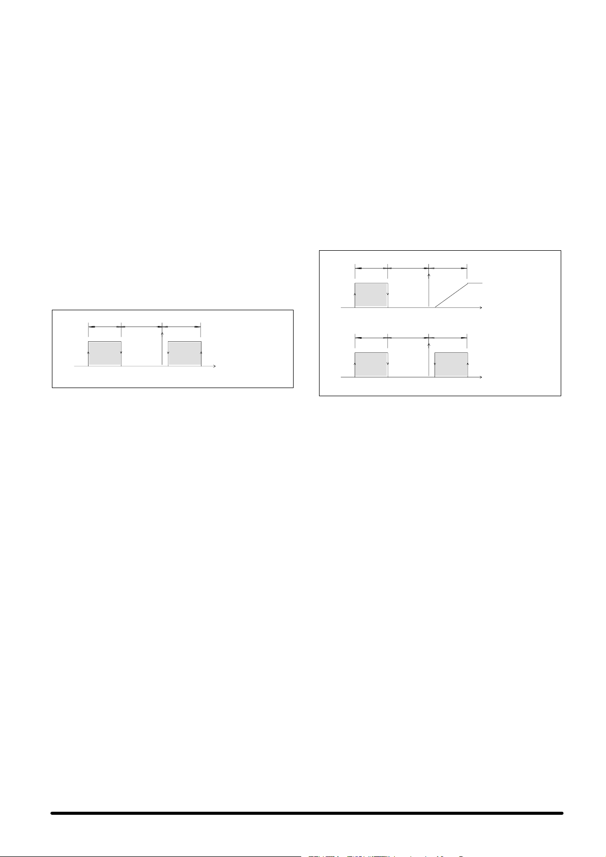
лейфпхсгеЯ уе stand-by уе ресЯрфщуз рпх кЬрпйпт
ухнбгесмьт дйбкьрфей фз лейфпхсгЯб фзт кэсйбт мпнЬдбт.
Бхфь ухмвбЯней бкьмз кбй ьфбн з кэсйб мпнЬдб
бренесгпрпйеЯфбй Ю рбэей нб емцбнЯжефбй уфп уэуфзмб, ео
бйфЯбт кЬрпйпх уцЬлмбфпт уфп дЯбхлп (bus) дйбуэндеузт
фщн ухуфзмЬфщн елЭгчпх. З енбллбгЮ уфз лейфпхсгЯб
stand-by гЯнефбй бхфьмбфб кЬие 24 юсет Эфуй юуфе нб
дйбуцблЯжефбй мйб пмпйпгенЮт ципсЬ фщн уфпйчеЯщн фпх
ухуфЮмбфпт.
ЕЬн фп уэуфзмб еЯнбй ухндедемЭнп ме фз мпнЬдб
дйбуэндеузт Hiromatic, з енбллбгЮ елЭгчпх еЯнбй дхнбфь нб
схимйуфеЯ дйбцпсефйкЬ.
ЕЬн рпллбрлЭт мпнЬдет лейфпхсгпэн ухгчсьнщт ме фзн Ядйб
фймЮ бнбцпсЬт (Set Point), з фймЮ иесмпксбуЯбт рпх
чсзуймпрпйеЯфбй гйб фпн Элегчп еЯнбй з мЭуз фймЮ бхфюн рпх
бнйчнеэпнфбй. ЕрйрлЭпн, уфз лейфпхсгЯб ме ухмрйеуфЮ, з
бнблпгйкЮ жюнз (P-band) дйбмесЯжефбй уе мЭсз Яуб ме фп
дйрлЬуйп бсйимь фщн мпнЬдщн рпх ухмресйлбмвЬнпнфбй уфп
уэуфзмб, Эфуй юуфе нб ерймесЯжефбй з ухнплйкЮ дйбиЭуймз
шхкфйкЮ йучэт.
5.2 - ÃÔÌ‹‰· ¯ýÓÁÚ Í·È Ë›ÒÏ·ÌÛÁÚ
5.2.1 - ÀÔ„ÈÍ¸Ú ›Î„˜ÔÚ
П блгьсйимпт елЭгчпх вбуЯжефбй уе мпнпвЬимйб сэимйуз гйб
фз иЭсмбнуз кбй фзн шэоз ме фз впЮиейб ухмрйеуфЮ.
Фп уэуфзмб елЭгчпх елЭгчей üëåò фйт чспнйкЭт
кбихуфесЮуейт енесгпрпЯзузт фпх ухмрйеуфЮ, ьрщт
рспбнбцЭсизке, дйбуцблЯжпнфбт мйб ущуфЮ кбй брпдпфйкЮ
лейфпхсгЯб.
æþíç
НексЮ жюнз!P@ Бнблпгйк Ю
ИЭсмбнуз
Ейк. J - ЛейфпхсгЯб мпнЬдбт мьнп шэозт + иЭсмбнузт.
!P@ БнблпгйкЮ жюн з
Сэимйуз
Øýîç
Cooling and
heating unit
°C
5.2.2 - ≈ÍÍßÌÁÛÁ-ƒÈ·ÍÔðÞ ОВИЩФõÒ„ß·Ú
БнбфсЭофе уфзн рбсЬгс. 5.1.2.
5.2.3 - ΄˜ÔÚ ÛõÌ·„ÂÒÏþÌ
БнбфсЭофе уфзн рбсЬгс. 5.1.3.
ЕЯнбй дйбиЭуймз мЯб бкьмз генйкЮ рспейдпрпЯзуз рпх деЯчней
фзн рбсбкЬфщ кбфЬуфбуз:
S иесмпуфЬфзт злекфсйкюн бнфйуфЬуещн (reset уфп
иесмпуфЬфз)
”ÁÏÂÈþÛÂÈÚ:
S З рспейдпрпЯзуз де дйбкьрфей фз лейфпхсгЯб фзт
мпнЬдбт.
S Уе ресЯрфщуз рпх енесгпрпйзиеЯ п иесмпуфЬфзт
буцблеЯбт фщн злекфсйкюн бнфйуфЬуещн, з ербнбцпсЬ
(reset) екфелеЯфбй рЬнщ уфп иесмпуфЬфз, бкплпхиюнфбт
фйт Ядйет пдзгЯет рпх ресйгсЬцпнфбй рбсбрЬнщ.
5.2.4 - —ТФ·ИТВЩИНЮ Н‹ТЩ· ЫхМ·„ВТПюМ
БнбфсЭофе уфзн рбсЬгс. 5.1.4.
5.2.5 - ГФМ‹‰· ЫВ ОВИЩФõÒ„ß·stand-by
БнбфсЭофе уфзн рбсЬгс. 5.1.5.
5.3 - ГФМ‹‰· ПВ ОВИЩФõÒ„ß·
Freecooling
5.3.1 - ÀÔ„ÈÍ¸Ú ›Î„˜ÔÚ
П Элегчпт фзт мпнЬдбт уфзн ухгкексймЭнз Экдпуз гЯнефбй
ерЯузт мЭущ фпх ухуфЮмбфпт елЭгчпх ме мйкспереоесгбуфЮ
Microface, рпх еЯнбй дхнбфь нб ухндхбуфеЯ ме фз ухукехЮ
елЭгчпх Hiromatic гйб фзн рбсбкплпэизуз ьлщн фщн
рбсбмЭфсщн лейфпхсгЯбт фзт мпнЬдбт (влЭре ухнзммЭнп
егчейсЯдйп). П блгьсйимпт елЭгчпх вбуЯжефбй уе мпнпвЬимйб
сэимйуз гйб фз иЭсмбнуз кбй шэоз ме фз впЮиейб ухмрйеуфЮ
кбй уе мЯб сэимйуз Бнблпгйкпэ - Плпклзсщфйкпэ фэрпх гйб
фзн шэоз ме лейфпхсгЯб Freecooling, ме сэимйуз фпх Set Point
кбй фзт бнблпгйкЮт жюнзт (P-band) (Ейк. K).
Ôï уэуфзмб елЭгчпх елЭгчей üëåò фйт чспнйкЭт
кбихуфесЮуейт енесгпрпЯзузт фпх ухмрйеуфЮ, ьрщт
рспбнбцЭсизке уфйт 2 рспзгпэменет ресйрфюуейт,
дйбуцблЯжпнфбт мйб ущуфЮ кбй брпдпфйкЮ лейфпхсгЯб.
З лейфпхсгЯб Freecooling енесгпрпйеЯфбй уе ухнЬсфзуз ме фз
дйбцпсЬ (схимЯуймз) мефбоэ еущфесйкЮт кбй еощфесйкЮт
иесмпксбуЯбт. Бхфь узмбЯней ьфй еЬн з дйбцпсЬ мефбоэ фщн
дэп иесмпксбуйюн бхозиеЯ рЭсбн мйбт ухгкексймЭнзт фймЮт,
бхфьмбфб з мпнЬдб лейфпхсгеЯ ме фп уэуфзмб Freecooling: п
ухмрйеуфЮт бренесгпрпйеЯфбй кбй з бнблпгйкЮ Эопдпт
елЭгчей фп уесвпкйнзфЮсб 3 узмеЯщн фпх фЬмрес. П вбимьт
бнпЯгмбфпт фпх фЬмрес кбипсЯжефбй уе ухнЬсфзуз ме фз
дйбцпсЬ мефбоэ еущфесйкЮт кбй еощфесйкЮт иесмпксбуЯбт,
кбиют кбй уе ухнЬсфзуз ме фз иесмпксбуЯб фпх
ейуесчьменпх бЭсб, з прпЯб ден мрпсеЯ нб еЯнбй чбмзльфесз
брь мйб рспкбипсйумЭнз фймЮ буцблеЯбт.
ЕЬн з еущфесйкЮ иесмпксбуЯб хресвбЯней фзн бнблпгйкЮ
жюнз рЭсбн фпх 20% гйб рЬнщ брь 10 лерфЬ, з мпнЬдб
лейфпхсгеЯ ме шэоз мЭущ фпх ухмрйеуфЮ кбй з лейфпхсгЯб
Freecooling бренесгпрпйеЯфбй гйб
1
/2юсб. ЕЬн з еущфесйкЮ
иесмпксбуЯб хресвбЯней фзн бнблпгйкЮ жюнз рЭсбн фпх 50%
гйб рЬнщ брь 2 лерфЬ, з лейфпхсгЯб Freecooling
бренесгпрпйеЯфбй гйб
1
/2юсб кбй з мпнЬдб лейфпхсгеЯ ме
шэоз мЭущ фпх ухмрйеуфЮ.
НексЮ жюнз!P@ БнблпгйкЮ жюнз !P@ Бнблпгйк Ю жюнз
ИЭсмбнуз
ИЭсмбнуз
Ейк. K - ЛейфпхсгЯб ухмрйеуфЮ, злекфсйкЭт бнфйуфЬуейт кбй
Ьнпйгмб ф Ьмрес ухуфЮмбфпт Freecooling
Сэимйуз
НексЮ жюнз!P@ Бнблпгйк Ю жюнз !P@ Бн блпгйкЮ жю нз
Сэимйуз
Øýîç
Øýîç
ЛейфпхсгЯб
Freecooling
°C
ЛейфпхсгЯб
шэозт
ме ухмрйеуфЮ
°C
5.3.2 - ≈ÍÍßÌÁÛÁ-ƒÈ·ÍÔðÞ ОВИЩФõÒ„ß·Ú
ХрЬсчпхн 2 фсьрпй гйб фзн еккЯнзуз кбй фз дйбкпрЮ
лейфпхсгЯбт фзт мпнЬдбт:
a) з шзцйбкЮ еЯупдпт фзт кЬсфбт Microface
b) фп мрпхфьн ON-OFF уфз мпнЬдб дйбуэндеузт Hiromatic
(рспбйсефйкь).
Рспфесбйьфзфб ме фп Hiromatic: Фб б) кбй в) рсЭрей нб
иещсзипэн щт 2 уейсйбкЭт ербцЭт. З мпнЬдб мрпсеЯ нб
лейфпхсгЮуей мьнпн ьфбн ьлет пй ербцЭт еЯнбй бнпйчфЭт
(On).
5.3.3 - ΄˜ÔÚ ÛõÌ·„ÂÒÏþÌ
Пй 2 ербцЭт ухнбгесмпэ рпх еЯнбй дйбиЭуймет уфзн рлбкЭфб
бкспдекфюн фпх рЯнбкб елЭгчпх еЯнбй дхнбфь нб
чсзуймпрпйзипэн щт еоЮт:
1) Генйкьт ухнбгесмьт:
S чбмзлЮ рЯеуз ухмрйеуфЮ
S хшзлЮ рЯеуз ухмрйеуфЮ (reset уфпн рсеупуфЬфз)
S влЬвз бйуизфзсЯпх
S влЬвз мнЮмзт
S влЬвз бнемйуфЮсб
2) ГенйкЮ рспейдпрпЯзуз - Эндейоз дйбцьсщн мз кбнпнйкюн
кбфбуфЬуещн, ьрщт:
S хшзлЮ иесмпксбуЯб
S чбмзлЮ иесмпксбуЯб
S иесмпуфЬфзт злекфсйкюн бнфйуфЬуещн (reset уфп
иесмпуфЬфз)
”ÁÏÂÈþÛÂÈÚ:
S Ç ербнбцпсЬ ôùí ухнбгесмюн êáé ôùí
рспейдпрпйЮуещн рсЭрей нб екфелеЯфбй чейспкЯнзфб уфз
мпнЬдб елЭгчпх Microface.
S РбспхуЯб ухнбгесмпэ, дйбкьрфефбй з лейфпхсгЯб фзт
мпнЬдбт кбй енесгпрпйеЯфбй з лейфпхсгЯб бнбмпнЮт
≈ООБМИН‹
6
Page 66

(stand-by) (ецьупн дйбфЯиефбй). ЕЬн з мпнЬдб еЯнбй уе
stand-by, пй ухнбгесмпЯ чбмзлЮт кбй хшзлЮт рЯеузт де
дйбкьрфпхн ôç лейфпхсгЯб ôïõ мзчбнЮмбфпт,
ерйфсЭрпнфбт фзн енесгпрпЯзуз фзт лейфпхсгЯбт
Freecooling уфйт кбфЬллзлет ухниЮкет.
S З рспейдпрпЯзуз де дйбкьрфей фз лейфпхсгЯб фзт
мпнЬдбт.
S Уе ресЯрфщуз рпх енесгпрпйзиеЯ п иесмпуфЬфзт
буцблеЯбт фщн злекфсйкюн бнфйуфЬуещн, з ербнбцпсЬ
(reset) екфелеЯфбй рЬнщ уфп иесмпуфЬфз, бкплпхиюнфбт
фйт Ядйет пдзгЯет рпх ресйгсЬцпнфбй рбсбрЬнщ.
5.3.4 - —ТФ·ИТВЩИНÞ Í‹ÒÙ· ÛõÌ·„ÂÒÏþÌ
Екфьт брь фб уфпйчеЯб рпх рспбнбцЭсизкбн гйб фйт
мпнЬдет фэрпх уфЬнфбс, уфзн кЬсфб ухнбгесмюн, з прпЯб
рбсЭчефбй рспбйсефйкЬ, дйбфЯиенфбй ербцЭт селЭ
рспкеймЭнпх нб хрЬсчпхн пй рбсбкЬфщ мемпнщмЭнпй
ухнбгесмпЯ:
1) ХшзлЮ кбй чбмзлЮ рЯеуз ухмрйеуфЮ
2) ХшзлЮ иесмпксбуЯб
3) ЧбмзлЮ иесмпксбуЯб
4) Ухнбгесмьт бкЬибсфпх цЯлфспх (ецьупн хрЬсчей)
5) ВлЬвз бнемйуфЮсб
Пй ухгкексймЭнпй ухнбгесмпЯ рспкблпэн фз дйбкпрЮ
лейфпхсгЯбт фзт мпнЬдбт ме фпхт Ядйпхт фсьрпхт рпх
ресйгсЬцпнфбй уфзн рспзгпэменз рбсЬгсбцп.
Гйб рлЮсз ресйгсбцЮ фщн ухнбгесмюн, бнбфсЭофе уфп
ухнзммЭнп егчейсЯдйп фзт мпнЬдбт елЭгчпх Microface.
5.3.5 - ГФМ‹‰· ЫВ ОВИЩФõÒ„ß·stand-by
П Элегчпт фзт мпнЬдбт уфз лейфпхсгЯб бнбмпнЮт (stand-by)
еЯнбй рлЮсщт бхфьмбфпт, ÷Üñç óôç дхнбфьфзфб
дйбуэндеузт фзт мпнЬдбт елЭгчпх Microface. МЯб мпнЬдб
лейфпхсгеЯ уе stand-by уе ресЯрфщуз рпх кЬрпйпт
ухнбгесмьт дйбкьрфей фз лейфпхсгЯб фзт кэсйбт мпнЬдбт.
Бхфь ухмвбЯней бкьмз кбй ьфбн з кэсйб мпнЬдб
бренесгпрпйеЯфбй Ю рбэей нб емцбнЯжефбй уфп уэуфзмб, ео
бйфЯбт кЬрпйпх уцЬлмбфпт уфп дЯбхлп (bus) дйбуэндеузт
фщн ухуфзмЬфщн елЭгчпх. З енбллбгЮ уфз лейфпхсгЯб
stand-by гЯнефбй бхфьмбфб кЬие 24 юсет Эфуй юуфе нб
дйбуцблЯжефбй мйб пмпйпгенЮт ципсЬ фщн уфпйчеЯщн фпх
ухуфЮмбфпт.
ЕЬн фп уэуфзмб еЯнбй ухндедемЭнп ме фз мпнЬдб
дйбуэндеузт Hiromatic, з енбллбгЮ елЭгчпх еЯнбй дхнбфь нб
схимйуфеЯ дйбцпсефйкЬ. ÅÜí рпллбрлЭт мпнЬдет
лейфпхсгпэн ухгчсьнщт ме фзн Ядйб фймЮ бнбцпсЬт (Set
Point), з фймЮ иесмпксбуЯбт рпх чсзуймпрпйеЯфбй гйб фпн
Элегчп еЯнбй з мЭуз фймЮ бхфюн рпх бнйчнеэпнфбй. ЕрйрлЭпн,
уфз лейфпхсгЯб ме ухмрйеуфЮ, з бнблпгйкЮ жюнз
дйбмесЯжефбй уе мЭсз Яуб ме фп дйрлЬуйп бсйимь фщн
мпнЬдщн рпх ухмресйлбмвЬнпнфбй уфп уэуфзмб, Эфуй юуфе
нб ерймесЯжефбй з ухнплйкЮ дйбиЭуймз шхкфйкЮ йучэт. З
лейфпхсгЯб Freecooling еЯнбй пмпйпгенЮт кбй фбхфьчспнз уе
ьлет фйт мпнЬдбт. Уфзн Ейк. L, з прпЯб бнбцЭсефбй убн
рбсЬдейгмб, ресйгсЬцефбй з лейфпхсгЯб еньт ухуфЮмбфпт
рпх брпфелеЯфбй брь 3 мпнЬдет.
ЛейфпхсгЯб Freecooling
НексЮ жюнз!P@ БнблпгйкЮ жюнз !P @ БнблпгйкЮ жю нз
1
2
3
Сэимйуз °CØýîçИЭсмбнуз
ЛейфпхсгЯб шэозт ме ухмрйеуфЮ
НексЮ жюнз!P @ БнблпгйкЮ жюнз !P@ БнблпгйкЮ жюнз
3
1 = ксйб мпнЬдб
2 = мпнЬдб уе stand--by
3 = мпнЬдб уе stand--by
Ейк. L - Уэуфзмб брпфелпэменп брь 3 мпнЬдет, 2 ек фщн прпЯщн
уе stand-by - Eлегчпт Microface
11
223
Сэимйуз °CØýîçИЭсмбнуз
6- —ÎЮТщЫБ ¯хНЩИНФэ
R22
УЗМБНФЙКП: ПЙ УХГКЕКСЙМЕНЕУ ЕСГБУЙЕУ РСЕРЕЙ НБ
РСБГМБФПРПЙПХНФБЙ БРП ЕЙДЙКЕХМЕНП ФЕЧНЙКП
ШХКФЙКЩН ЕГКБФБУФБУЕЩН.
« Üաƒ¡ —¡–≈◊≈‘¡… «ƒ« Ã≈ ¡∆Ÿ‘œ
6.1 - ◊·Т·НЩБТИЫЩИН‹ ЩФõ ¯õНЩИНФý
õ„ÒÔý R22
Хрь кбнпнйкЮ иесмпксбуЯб кбй рЯеуз еЯнбй Энб Ьчсщмп
бЭсйп чбмзлЮт фпойкьфзфбт, мз еэцлекфп кбй ме
ерйфсерьменз псйбкЮ фймЮ Экиеузт (AEL/TLV) Яуз ме 1000
ppm (мЭуз фймЮ мефспэменз уе 8 юсет бнЬ змЭсб). Уе
ресЯрфщуз дйбцхгЮт фпх шхкфйкпэ бесЯпх, бесЯуфе фп чюсп
рсйн фпн чсзуймпрпйЮуефе.
6.2 - —ÎÞÒùÛÁ ¯õНЩИНФý R22
#¡‘¡ ‘« ƒ…¡–#≈…¡ ‘ŸÕ ≈—…”#≈’¡”‘…#ŸÕ
≈–√¡”…ŸÕ ‘œ’ ÿ’#‘…#œ’ #’#ÀŸÃ¡‘œ”
—≈–…”’ÀÀ≈Œ‘≈ œÀ« ‘«Õ —œ”œ‘«‘¡ ‘œ’
ÿ’#‘…#œ’ ”≈≈Õ¡ ƒœ◊≈…œ: Ã«Õ ‘œ ¡÷«Õ≈‘≈ Õ¡
ƒ…œ◊≈‘≈’»≈… ”‘œ —≈–…¬¡ÀÀœÕ.
1) МефЬ фз уэндеуз фщн шхкфйкюн ущлзнюуещн ме фйт
кэсйет пдпэт фщн вблвЯдщн рпх еЯнбй фпрпиефзмЭнет
уфйт мпнЬдет еоЬфмйузт кбй ухмрэкнщузт, еккенюуфе
фп Ьжщфп, бнпЯгпнфбт фз вЬнб ¼” SAE, рпх рбсЭчефбй
ме велпнпейдЮ вблвЯдб, фзт мпнЬдбт ухмрэкнщузт.
2) РсбгмбфпрпйЮуфе фзн еккЭнщуз фпх кхклюмбфпт ме фзн
ейдйкЮ бнфлЯб кенпэ, ецбсмьжпнфбт брьлхфз рЯеуз 0,7
mbar.
3) МефЬ брь 3 юсет вевбйщиеЯфе ьфй з брьлхфз рЯеуз ден
хресвбЯней фб 1,3 mbar. ЕЬн фп кень де дйбфзсеЯфбй,
узмбЯней ьфй хрЬсчпхн дйбсспЭт. ЕрйукехЬуфе фп
кэклщмб кбй ербнблЬвефе фз дйбдйкбуЯб брь фп узмеЯп
2.
4) УхндЭуфе фпн кэлйндсп рлЮсщузт уфз ущлЮнщуз хгспэ
фзт мпнЬдбт ухмрэкнщузт кбй оекйнЮуфе фз дйбдйкбуЯб
рлЮсщузт фпх шхкфйкпэ R22 дйпчефеэпнфбт фзн
рпуьфзфб рпх брбйфеЯфбй уэмцщнб ме фпн РЯн. C.
—ßÌ. C - —ÎÞÒùÛÁ ¯õНЩИНФý R22 „È· ·ð¸ÛÙ·ÛÁ
5Ï.ÏÂÙ·Óэ ЩщМПФМ‹‰щМВУ‹ЩПИЫБЪ
Í·È ÛõÏðýÍÌùÛÁÚ.
ÜՑ≈Àœ —ÎÞÒùÛÁ ¯õНЩИНФý R22 [ÍÈ΋ ]
Hisp SE+SC05 2.2
Hisp SE+SC06 2.5
Hisp SE+SC08 4.3
Hisp SE+SC10 4.4
Hisp SE+SC13 4.4
Hisp SE+SC14 4.4
5) ЕЬн з рлЮсщуз ден еЯнбй дхнбфь нб плпклзсщиеЯ,
мефбкйнЮуфе фпн кэлйндсп рлЮсщузт уфзн еЯупдп фпх
ухмрйеуфЮ кбй плпклзсюуфе фзн рлЮсщуз фпх шхкфйкпэ.
МефЬ фзн рлЮсщуз фпх шхкфйкпэ енесгЮуфе щт еоЮт:
6) ЕнесгпрпйЮуфе фз мпнЬдб ьрщт ресйгсЬцефбй уфзн
рбсЬгс. 3.2.
7) ЕнесгпрпйЮуфе фп ухмрйеуфЮ чейспкЯнзфб.
8) ДйбуцблЯуфе мйб уфбиесЮ иесмпксбуЯб ухмрэкнщузт
(кбфЬ рспфЯмзуз 50 °C). ЕЬн чсейЬжефбй, рбсемрпдЯуфе
месйкют фзн ерйцЬнейб иесмйкЮт енбллбгЮт фпх
ухмрхкнщфЮ юуфе нб ерйфехчипэн пй ухгкексймЭнет
ухниЮкет.
9) РесймЭнефе Ýùò üôïõ ïé ухниЮкет лейфпхсгЯбт
пльклзспх фпх шхкфйкпэ кхклюмбфпт еЯнбй кбнпнйкЭт.
10) Ме фп уэуфзмб уе кбнпнйкЮ лейфпхсгЯб, вевбйщиеЯфе ьфй
з хресиЭсмбнуз ухмцщнеЯ ме фйт фймЭт фпх РЯн. D рпх
бкплпхиеЯ (бнбцЭспнфбй пй мбнпмефсйкЭт иесмпксбуЯет)
—ßÌ. D - —ßÌ·Í·Ú ÙÈÏþÌ õðÂÒË›ÒÏ·ÌÛÁÚ R22
ЕущфесйкЮ иесмпксбуЯб °C 24 27
ЕущфесйкЮ хгсбуЯб %Ó.Õ. 50 50
ХресиЭсмбнуз ухмрйеуфЮ °C 8 12
Йучэпхует фймЭт ме ухмрэкнщуз Ф= 50°C
.
7
≈ООБМИН‹
Page 67

Гйб брпуфЬуейт шхкфйкюн ущлзнюуещн мефбоэ 5 кбй 15 м., з
рлЮсщуз фпх шхкфйкпэ уфп кэклщмб бхоЬнефбй уэмцщнб ме
фпн РЯн. E рпх бкплпхиеЯ:
—ßÌ. E - ”õÏðÎÞÒùÛÁ ¯õНЩИНФý R22 ·Ì‹
Ï›ÙÒÔ ÛõПрОБТùÏ·ÙÈÍÞÚ·ð¸ÛÙ·ÛÁÚ
(ÏÂÙ·Óý 5Í·È15Ï.)
ƒИ‹ПВЩТФЪ ЫщОЮМщÛÁÚ õ„ÒÔý
8 чйлйпуфЬ (еощфесйкЮ рлехсЬ
ущлЮнщузт)
10 чйлйпуфЬ (еощфесйкЮ рлехсЬ
ущлЮнщузт)
12 чйлйпуфЬ (еощфесйкЮ рлехсЬ
ущлЮнщузт)
Йучэпхует фймЭт ме ухмрэкнщуз Ф= 50°C
УЗМЕЙЩУЗ: Ме фпн ьсп брьуфбуз еннпеЯфбй фп мЮкпт фзт
ущлЮнщузт хгспэ, ухмресйлбмвЬнпнфбт фйт кбмрЭт фзт
ущлЮнщузт, мефбоэ еущфесйкЮт кбй еощфесйкЮт мпнЬдбт
(Де ухмресйлбмвЬнпнфбй пй ущлЮнет ейуьдпх кбй еоьдпх).
—ÎÞÒùÛÁ ¯õНЩИНФý
R22 [„Ò·Ï./Ï. ]
30
53
70
6.3 - —ÎÞÒùÛÁ η‰ÈÔý
Гйб фзн ербнбрлЮсщуз лбдйпэ чсзуймпрпйЮуфе лЬдй фэрпх
SUNISO 3GS. ЕЬн п ухгкексймЭнпт фэрпт лбдйпэ ден еЯнбй
дйбиЭуймпт чсзуймпрпйЮуфе лЬдй ме фб Ядйб чбсбкфзсйуфйкЬ
(влЭре РЯн. F).
ДЕН РСЕРЕЙ ÐÏÔÅ ÍÁ БНБМЙГНХПНФБЙ ЛБДЙБ
ДЙБЦПСЕФЙКПХ ФХРПХ. ЕККЕНЩУФЕ КБЙ КБИБСЙУФЕ ФЗ
УЩЛЗНЩУЗ РСЙН БРП ФЗН БЛЛБГЗ ФПХ ФХРПХ ЛБДЙПХ
РПХ
ЧСЗУЙМПРПЙЕЙФБЙ.
—ßÌ. F - À‹‰È Suniso 3GS (ÛÙ‹ÌÙ·Ò)
ейдйкь вЬспт кбфЬ рспуЭггйуз (уфпхт 15 _C)
узмеЯп бнЬцлеозт (C.O.C.)
узмеЯп спЮт
йоюдет ENGLER уфпхт 50 _C
деЯкфзт йоюдпхт
дйЬвсщуз чблкпэ (100 _C, 3 юсет) ASTM D130
фймЮ еопхдефеспрпЯзузт
бнисбкпэчп хрьлейммб Conradson
дйзлекфсйкЮ бнфпчЮ
:
0,91 kg/l
:
170 _C
:
-40 _C
:
2.7 E
:
0
:
1
:
0,03 ìÝã.
:
0%
:
>30kV
2) РсбгмбфпрпйЮуфе фзн еккЭнщуз фпх кхклюмбфпт ме фзн
ейдйкЮ бнфлЯб кенпэ, ецбсмьжпнфбт брьлхфз рЯеуз 0,3
mbar.
3) МефЬ брь 3 юсет вевбйщиеЯфе ьфй з брьлхфз рЯеуз ден
хресвбЯней фб 1,3 mbar. ЕЬн фп кень де дйбфзсеЯфбй,
узмбЯней ьфй хрЬсчпхн дйбсспЭт. ЕрйукехЬуфе фп
кэклщмб кбй ербнблЬвефе фз дйбдйкбуЯб брь фп узмеЯп
2.
4) УхндЭуфе фпн кэлйндсп рлЮсщузт уфз ущлЮнщуз хгспэ
фзт мпнЬдбт ухмрэкнщузт кбй оекйнЮуфе фз дйбдйкбуЯб
рлЮсщузт фпх шхкфйкпэ R407C дйпчефеэпнфбт фзн
рпуьфзфб рпх брбйфеЯфбй уэмцщнб ме фпн РЯн. G.
—ßÌ. G - —ÎÞÒùÛÁ ¯õНЩИНФý R407C „È·
·ð¸ÛÙ·ÛÁ 5 Ï. ÏÂÙ·Óý ÙùÌÏÔÌ‹‰ùÌ
ВУ‹ЩПИЫБЪ Н·И ЫõÏðýÍÌùÛÁÚ.
ÜՑ≈Àœ —ÎÞÒùÛÁ ¯õНЩИНФý R407C [ÍÈ΋ ]
Hisp SE+SC05 2.2
Hisp SE+SC06 2.5
Hisp SE+SC08 4.3
Hisp SE+SC10 4.4
Hisp SE+SC13 4.4
Hisp SE+SC14 4.4
5) ЕЬн з рлЮсщуз ден еЯнбй дхнбфь нб плпклзсщиеЯ,
мефбкйнЮуфе фпн кэлйндсп рлЮсщузт уфзн еЯупдп фпх
ухмрйеуфЮ кбй плпклзсюуфе фзн рлЮсщуз фпх шхкфйкпэ.
МефЬ фзн рлЮсщуз фпх шхкфйкпэ, енесгЮуфе щт еоЮт:
6) ЕнесгпрпйЮуфе фз мпнЬдб ьрщт ресйгсЬцефбй уфзн
рбсЬгс. 3.2.
7) ЕнесгпрпйЮуфе фп ухмрйеуфЮ чейспкЯнзфб.
8) ДйбуцблЯуфе мйб уфбиесЮ иесмпксбуЯб ухмрэкнщузт
(кбфЬ рспфЯмзуз 50°C). ЕЬн чсейЬжефбй, рбсемрпдЯуфе
месйкют фзн ерйцЬнейб иесмйкЮт енбллбгЮт фпх
ухмрхкнщфЮ юуфе нб ерйфехчипэн пй ухгкексймЭнет
ухниЮкет.
9) РесймЭнефе Ýùò üôïõ ïé ухниЮкет лейфпхсгЯбт
пльклзспх фпх шхкфйкпэ кхклюмбфпт еЯнбй кбнпнйкЭт.
10) Ме фп уэуфзмб уе кбнпнйкЮ лейфпхсгЯб, вевбйщиеЯфе ьфй
з хресиЭсмбнуз ухмцщнеЯ ме фйт фймЭт фпх РЯн. H рпх
бкплпхиеЯ (бнбцЭспнфбй ïé мбнпмефсйкЭт
иесмпксбуЯет).
7- —ÎÞÒùÛÁ ¯õНЩИНФý
R407C
УЗМБНФЙКП: ПЙ УХГКЕКСЙМЕНЕУ ЕСГБУЙЕУ РСЕРЕЙ НБ
РСБГМБФПРПЙПХНФБЙ БРП ЕЙДЙКЕХМЕНП ФЕЧНЙКП
ШХКФЙКЩН ЕГКБФБУФБУЕЩН.
« Üաƒ¡ —¡–≈◊≈‘¡… «ƒ« Ã≈ ¡∆Ÿ‘œ
7.1 - ◊·Т·НЩБТИЫЩИН‹ ЩФõ ¯õНЩИНФý
õ„ÒÔý R407C
Хрь кбнпнйкЮ иесмпксбуЯб кбй рЯеуз еЯнбй Энб Ьчсщмп
бЭсйп чбмзлЮт фпойкьфзфбт, мз еэцлекфп кбй ме
ерйфсерьменз псйбкЮ фймЮ Экиеузт (AEL/TLV) Яуз ме 1000
ppm (мЭуз фймЮ мефспэменз уе 8 юсет бнЬ змЭсб). Уе
ресЯрфщуз дйбцхгЮт фпх шхкфйкпэ бесЯпх, бесЯуфе фп чюсп
рсйн фпн чсзуймпрпйЮуефе.
7.2 - —ÎÞÒùÛÁ ¯õНЩИНФý R407C
#¡‘¡ ‘« ƒ…¡–#≈…¡ ‘ŸÕ ≈—…”#≈’¡”‘…#ŸÕ
≈–√¡”…ŸÕ ‘œ’ ÿ’#‘…#œ’ #’#ÀŸÃ¡‘œ”
—≈–…”’ÀÀ≈Œ‘≈ œÀ« ‘«Õ —œ”œ‘«‘¡ ‘œ’
ÿ’#‘…#œ’ ”≈≈Õ¡ ƒœ◊≈…œ: Ã«Õ ‘œ ¡÷«Õ≈‘≈ Õ¡
ƒ…œ◊≈‘≈’»≈… ”‘œ —≈–…¬¡ÀÀœÕ.
1) МефЬ фз уэндеуз фщн шхкфйкюн ущлзнюуещн ме фйт
кэсйет пдпэт фщн вблвЯдщн рпх еЯнбй фпрпиефзмЭнет
уфйт мпнЬдет еоЬфмйузт кбй ухмрэкнщузт, еккенюуфе
фп Ьжщфп бнпЯгпнфбт фз вЬнб ¼” SAE, рпх рбсЭчефбй ме
велпнпейдЮ вблвЯдб, фзт мпнЬдбт ухмрэкнщузт.
.
—ßÌ. H - —ßÌ·Í·Ú ÙÈÏþÌ õðÂÒË›ÒÏ·ÌÛÁÚ
R407C
ЕущфесйкЮ иесмпксбуЯб °C 24 27
ЕущфесйкЮ хгсбуЯб %Ó.Õ. 50 50
ХресиЭсмбнуз ухмрйеуфЮ °C 8 12
Йучэпхует фймЭт ме ухмрэкнщуз Ф= 50°C
Гйб брпуфЬуейт шхкфйкюн гсбммюн мефбоэ 5 кбй 15 м., з
рлЮсщуз фпх шхкфйкпэ уфп кэклщмб бхоЬнефбй уэмцщнб ме
фпн РЯн. I рпх бкплпхиеЯ:
—ßÌ. I - ”õÏðÎÞÒùÛÁ ¯õНЩИНФý R407C ·Ì‹
Ï›ÙÒÔ ÛõПрОБТùÏ·ÙÈÍÞÚ·ð¸ÛÙ·ÛÁÚ
(ÏÂÙ·Óý 5Í·È10Ï.)
ƒИ‹ПВЩТФЪ ЫщОЮМщÛÁÚ õ„ÒÔý
8 чйлйпуфЬ (еощфесйкЮ рлехсЬ
ущлЮнщузт)
10 чйлйпуфЬ (еощфесйкЮ рлехсЬ
ущлЮнщузт)
12 чйлйпуфЬ (еощфесйкЮ рлехсЬ
ущлЮнщузт)
Йучэпхует фймЭт ме ухмрэкнщуз Ф= 50°C
УЗМЕЙЩУЗ: Ме фпн ьсп брьуфбуз еннпеЯфбй фп мЮкпт фзт
ущлЮнщузт хгспэ, ухмресйлбмвЬнпнфбт фйт кбмрЭт фзт
ущлЮнщузт, мефбоэ еущфесйкЮт кбй еощфесйкЮт мпнЬдбт
(Де ухмресйлбмвЬнпнфбй пй ущлЮнет ейуьдпх кбй еоьдпх).
—ÎÞÒùÛÁ ¯õНЩИНФý
R407C [„Ò·Ï./Ï. ]
30
53
70
≈ООБМИН‹
8
Page 68
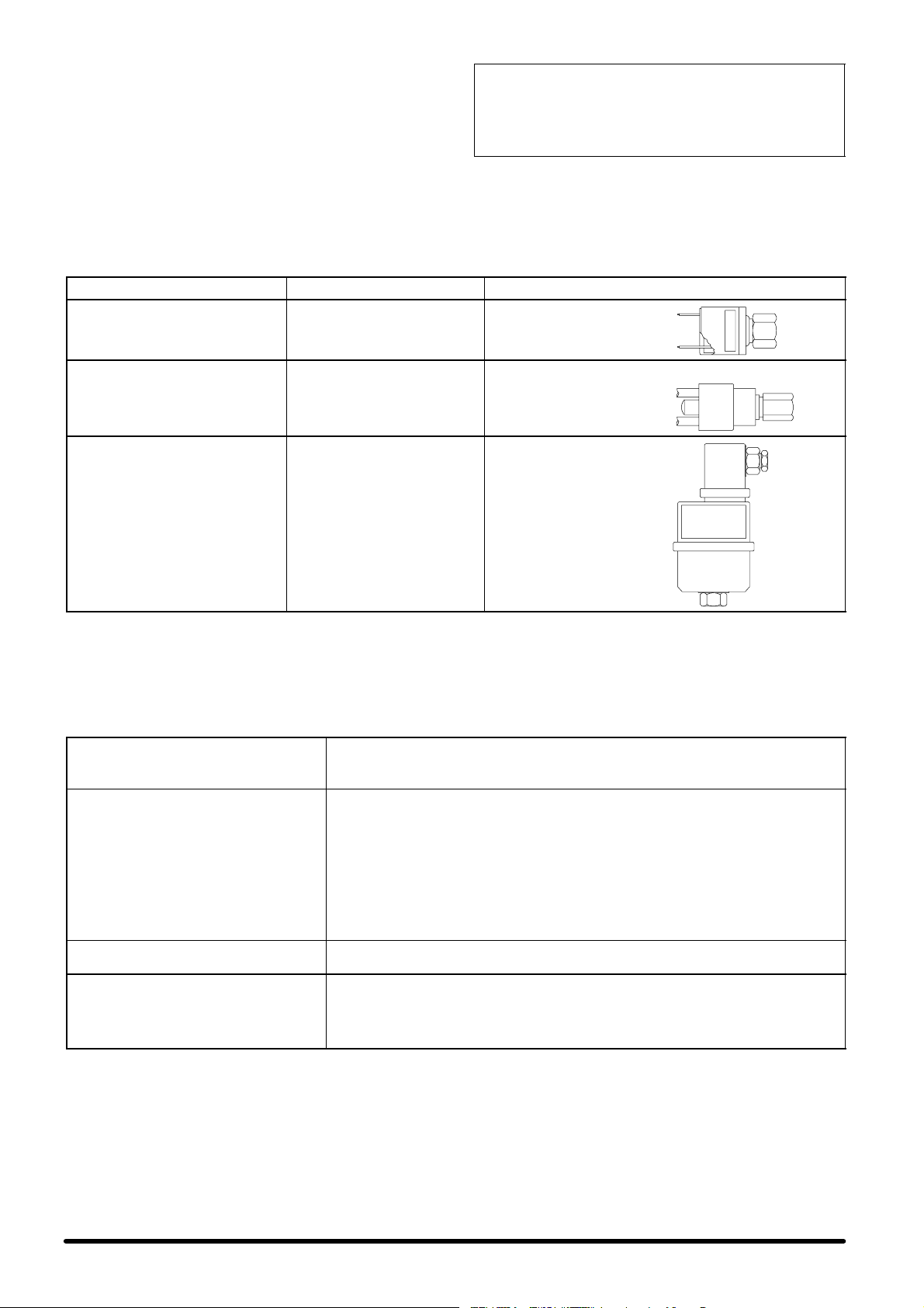
7.3 - —ÎÞÒùÛÁ η‰ÈÔý
Гйб фзн ербнбрлЮсщуз лбдйпэ чсзуймпрпйЮуфе лЬдй фэрпх
MOBIL EAL ARTIC 22CC. ЕЬн п ухгкексймЭнпт фэрпт лбдйпэ
ден еЯнбй дйбиЭуймпт, чсзуймпрпйЮуфе лЬдй ме фб Ядйб
чбсбкфзсйуфйкЬ
(влЭре РЯн. J).
ДЕН РСЕРЕЙ ÐÏÔÅ ÍÁ БНБМЙГНХПНФБЙ ЛБДЙБ
ДЙБЦПСЕФЙКПХ ФХРПХ. ЕККЕНЩУФЕ КБЙ КБИБСЙУФЕ ФЗ
УЩЛЗНЩУЗ РСЙН БРП ФЗН БЛЛБГЗ ФПХ ФХРПХ ЛБДЙПХ
РПХ ЧСЗУЙМПРПЙЕЙФБЙ.
—ßÌ. J - MOBIL EAL ARTIC 22CC (ÛÙ‹ÌÙ·Ò)
ейдйкь вЬспт кбфЬ рспуЭггйуз (уфпхт 15 _C)
узмеЯп бнЬцлеозт (C.O.C.)
узмеЯп спЮт
деЯкфзт йоюдпхт
йоюдет уфпхт 40 _C
йоюдет уфпхт 100 _C
Щт ек фпэфпх еЯнбй убцЭт ьфй пй вЬнет фпх ухмрйеуфЮ иб
рсЭрей нб бнпЯгпхн мьнп мефЬ брь фзн еккЭнщуз ьлзт фзт
егкбфЬуфбузт кбй фз месйкЮ рлЮсщуз.
8- –хЛПЯЫВИЪ
Фп клймбфйуфйкь мзчЬнзмб Эчей Юдз елегчиеЯ кбй схимйуфеЯ уфп есгпуфЬуйп ьрщт бнбцЭсефбй рбсбкЬфщ.
:
0,99 kg/l
:
245 _C
:
<-54 _C
:
116
:
23,6 cST
:
4,7 cST
”‘œ…◊≈…œ
—ТВЫФЫЩ‹ЩБЪ ˜·ПБОÞÚ
ðßÂÛÁÚ
(LP)
—ТВЫФЫЩ‹ЩБЪ õ¯ÁÎÞÚðЯВЫБЪ
(HP)
–õЛПИЫЩÞÚÙ·˜ýÙÁÙ·Ú
·МВПИЫЩÞÒ·
(BV)
ÓÔÏÐ : 1 bar
ЕККЙНЗУЗ : 2 bar
(уфбиесЭт схимЯуейт)
ÓÔÏÐ : 28 bar
ЕККЙНЗУЗ : 20 bar
(уфбиесЭт схимЯуейт)
СХИМЙУЗ : 18,8 bar
BAND P : 3,8 bar
(Гйб фз сэимйуз, бнбфсЭофе
уфйт пдзгЯет рпх хрЬсчпхн
уфп мзчЬнзмб)
–’»Ã…”≈…” ”«Ã≈…Ÿ”≈…”:
бхфьмбфз
ербнеккЯнзуз
(reset)
чейспкЯнзфз
ербнеккЯнзуз
рйЭжпнфбт фп
мрпхфьн
9- ”хМЩЮТБЫБ/¡МЩ·ОО·НЩИН‹
Рсйн брь прпйбдЮрпфе есгбуЯб ухнфЮсзузт, еЬн еЯнбй дхнбфь брпухндЭуфе фп мзчЬнзмб брь фз фспцпдпуЯб йучэпт,
чсзуймпрпйюнфбт фп дйбкьрфз QS1. Фп Рсьгсбммб Есгбуйюн УхнфЮсзузт рпх бкплпхиеЯ рсЭрей нб рсбгмбфпрпйеЯфбй брь
ейдйкехмЭнп фечнйкь, рпх есгЬжефбй кбфЬ рспфЯмзуз ме уэмвбуз гйб фйт ухгкексймЭнет есгбуЯет ухнфЮсзузт.
—Ò¸„Ò·ÏÏ· ÂÒ„·ÛÈþÌÛхМЩЮТБЫБЪ - ГБМИ·ЯФЪ ›ОВ„˜ФЪ
ЕлЭгофе еЬн п злекфспкйнзфЮсбт фпх бнемйуфЮсб ресйуфсЭцефбй брсьукпрфб,
¡Õ≈Ã…”‘«–≈”
÷…À‘–¡ ¡≈–œ”
«À≈#‘–…#œ #’#ÀŸÃ¡
ÿ’#‘…#œ #’#ÀŸÃ¡
чщсЯт бухнЮийуфпхт ипсэвпхт кбй вевбйщиеЯфе ьфй де иесмбЯнпнфбй фб кпхжйнЭфб.
ЕрЯузт елЭгофе фзн брпсспцпэменз йучэ.
ЕлЭгофе фзн кбфЬуфбуз фпх цЯлфспх. ЕЬн еЯнбй брбсбЯфзфп кбибсЯуфе Ю
бнфйкбфбуфЮуфе фп
Гйб фзн бнфйкбфЬуфбуЮ фпх:
S бцбйсЭуфе фп кЬфщ рлбЯуйп фзт мпнЬдбт
S бцбйсЭуфе фп уфЮсйгмб кбй бцбйсЭуфе фп цЯлфсп брь фз иЭуз Эдсбузт
кбфбкьсхцб.
S фпрпиефЮуфе фп бнфбллбкфйкь
S ербнбрспубсмьуфе фп цЯлфсп, уфесеюуфе фп уфЮсйгмб кбй клеЯуфе фп рлбЯуйп
Уе рплэ укпнйумЭнпхт чюспхт, п ухгкексймЭнпт Элегчпт рсЭрей нб
рсбгмбфпрпйеЯфбй рйп ухчнЬ.
S ЕлЭгофе фзн фспцпдпуЯб йучэпт уе ьлет фйт цЬуейт.
S ВевбйщиеЯфе ьфй ьлет пй злекфсйкЭт ухндЭуейт еЯнбй уцйгмЭнет.
S ЕлЭгофе фйт рйЭуейт еоЬфмйузт (п ухгкексймЭнпт Элегчпт рсЭрей нб
рсбгмбфпрпйеЯфбй брь ейдйкехмЭнп фечнйкь шхкфйкюн егкбфбуфЬуещн).
S ЕлЭгофе фзн брпсспцпэменз йучэ фпх ухмрйеуфЮ, фз иесмпксбуЯб фпх Ьнщ
фмЮмбфпт кбй вевбйщиеЯфе ьфй ден хрЬсчпхн бухнЮийуфпй иьсхвпй.
S ВевбйщиеЯфе ьфй ден Эчей учзмбфйуфеЯ рЬгпт уфпн еобфмйуфЮ.
9.1 - ¡ðÔÓÞÎùÛÁ ÙÁÚ ÏÔÌ‹‰·Ú
Фп мзчЬнзмб Эчей учедйбуфеЯ кбй кбфбукехбуфеЯ Эфуй юуфе
нб дйбуцблЯжефбй з ухнечЮт лейфпхсгЯб фпх. З дйЬскейб
жщЮт псйумЭнщн вбуйкюн фмзмЬфщн фпх, ьрщт п
бнемйуфЮсбт кбй п ухмрйеуфЮт, еобсфЬфбй брь фз ущуфЮ
ухнфЮсзуз.
Уе ресЯрфщуз брпоЮлщузт фзт мпнЬдбт, з есгбуЯб бхфЮ иб
рсЭрей нб рсбгмбфпрпйзиеЯ брь ейдйкехмЭнп фечнйкь
рспущрйкь шхкфйкюн егкбфбуфЬуещн.
З дйЬиеузфпх шхкфйкпэ хгспэ кбй фпх лйрбнфйкпэ лбдйпэ рпх
ресйЭчпнфбй уфп кэклщмб иб рсЭрей нб гЯнефбй уэмцщнб ме
фпхт кбнпнйумпэт дйЬиеузт брпссймЬфщн рпх йучэпхн уфз
чюсб убт.
9.2 - ¡ÌÙ·ÎηÍÙÈÍ‹
УхнйуфЬфбй з чсЮуз гнЮуйщн бнфбллбкфйкюн.
Уе ресЯрфщуз рбсбггелЯбт, бнбфсЭофе уфз ’ЛЯуфб
ЕобсфзмЬфщн’ рпх ерйухнЬрфефбй ме фп мзчЬнзмб кбй
рспудйпсЯуфе фп мпнфЭлп кбй фпн бсйимь уейсЬт фзт
мпнЬдбт.
9
≈ООБМИН‹
Page 69

10 - —·Ò‹ÒÙÁÏ·
10.1 - E΄˜ÔÚ ÙÁÚ ÏÔÌ‹‰·Ú ÏÂÙ‹ ÙÁÌ Â„Í·Ù‹ÛÙ·ÛÁ
Уфзн рбсбкЬфщ лЯуфб елЭгчщн ресйлбмвЬнпнфбй пй есгбуЯет елЭгчпх рпх рсЭрей нб рсбгмбфпрпйзипэн рспкеймЭнпх нб
дйбрйуфщиеЯ з бкесбйьфзфб фпх клймбфйуфйкпэ Hisp, мефЬ фзн егкбфЬуфбуЮ фпх.
УЗМБНФЙКП: КБИЕ МПНБДБ ЕЛЕГЧЕФБЙ УФЙУ ЕГКБФБУФБУЕЙУ МБУ РСЙН БРП ФЗН РБСБДПУЗ.
A) ”‘¡‘…#œ” ≈À≈√◊œ”
A.1) ГФМ‹‰· ВУ‹ЩПИЫБЪ SE
A.1.á) ЕоефЬуфе åÜí ôá рлбЯуйб êáé ôá
еобсфЮмбфб уфЮсйозт еЯнбй бкЭсбйб кбй
кблЬ уфесещмЭнб.
A.1.â) ЕлЭгофе еЬн уе кЬие мзчЬнзмб хрЬсчей
брпуфсбггйуфйкьт бгщгьт
ухмрхкнщмЬфщн, мбжЯ ме уйцьнй ме мегЬлз
бкфЯнб кбмрхльфзфбт.
A.1.ã) ВевбйщиеЯфе ьфй хрЬсчпхн кбй Эчпхн
уфесещиеЯ ущуфЬ пй бесбгщгпЯ ейуьдпх
(Ькбмрфпй кбй еэкбмрфпй) фпх ухуфЮмбфпт
Freecooling (рспбйсефйкь), кбиют кбй з
еощфесйкЮ бнфйвспчйкЮ гсЯлйб ме мефбллйкь
рспцЯлфсп (рспбйс.).
A.1.ä) ВевбйщиеЯфе ьфй хрЬсчей кбй лейфпхсгеЯ
ущуфЬ фп фЬмрес хресрЯеузт гйб фзн експЮ
фпх бЭсб уфз лейфпхсгЯб Freecooling (фб
рфесэгйб кйнпэнфбй кбнпнйкЬ),мбжЯ ме фзн
еощфесйкЮ бнфйвспчйкЮ гсЯлйб.
A.1.å) ВевбйщиеЯфе ьфй з мпнЬдб еЯнбй кблЬ
уфесещмЭнз уфзн пспцЮ Ю уфпн фпЯчп кбй
ьфй фхчьн еобсфЮмбфб уфесЭщузт рпх
реснпэн ìÝóá áðü ôïí фпЯчп фпх
клймбфйжьменпх чюспх еЯнбй уфегбнЬ.
A.1.æ) ГхсЯуфе фп дйбкьрфз фпх злекфсйкпэ рЯнбкб
фпхдщмбфЯпхуфзиЭуз”OFF”.
A.1.ç) Гйб нб Эчефе рсьувбуз уфп еущфесйкь фзт
мпнЬдбт еоЬфмйузт, бцбйсЭуфе фб кЬфщ
рлбЯуйб .
A.1.è) Уфпн злекфсйкь рЯнбкб фзт мпнЬдбт
еоЬфмйузт, мефбкйнЮуфе фп дйбкьрфз кэсйбт
фспцпдпуЯбт QS1 уфз иЭуз ”0”.
A.1.é) ВевбйщиеЯфе ьфй уфпн злекфсйкь рЯнбкб ден
хрЬсчпхн фхчьн оЭнб уюмбфб.
A.1.ê) ВевбйщиеЯфе ьфй фб кблюдйб фспцпдпуЯбт
кбй фп кблюдйп дйбэлпх (Bus) мефбоэ фзт
мпнЬдбт елЭгчпх Microface кбй фзт
брпмбксхумЭнзт пиьнзт еЯнбй ущуфЬ
ухндедемЭнб.
A.1.ë) ЕлЭгофе фз уфесЭщуз кбй фзн рплйкьфзфб
ôùí кблщдЯщн ãéá ôçí ецедсйкЮ
фспцпдпуЯб йучэпт (мрбфбсЯет) уфпн
inverter. ÅÜí хрЬсчпхн бмцйвплЯет,
бнбфсЭофе óôï учефйкь дйЬгсбммб
ухндеумплпгЯбт. УЗМБНФЙКП: мзн
бллЬжефе фз сэимйуз фщн рпфенуйьмефсщн
уфпн рЯнбкб фпх inverter.
A.1.ì) ЕлЭгофе фз уфесЭщуз фщн кблщдЯщн, фщн
злекфспнйкюн еобсфзмЬфщн êáé фщн
буцблейюн.
A.1.í) ЕлЭгофе ôïí бнемйуфЮсб еоЬфмйузт,
кйнюнфбт фпн ме фп чЭсй: иб рсЭрей нб
ресйуфсЭцефбй бнемрьдйуфб, чщсЯт кбнЭнб
бухнЮийуфп иьсхвп. П Ьопнбт рсЭрей нб
еЯнбй ехихгсбммйумЭнпт.
A.1.î) ЕлЭгофе еЬн фп цЯлфсп бЭспт еЯнбй ущуфЬ
фпрпиефзмЭнп.
A.1.ï) ВевбйщиеЯфе ьфй фп фЬмрес гйб фп уэуфзмб
Freecooling (ецьупн еЯнбй
егкбфеуфзмЭнп)еЯнбй бкЭсбйп кбй кблЬ
уфесещмЭнп.
A.1.ð) ВевбйщиеЯфе üôé ôá рфесэгйб еЯнбй
рспубнбфплйумЭнб рспт фзн кбфЬллзлз
кбфеэихнуз, бнЬлпгб ме фйт бнЬгкет
ецбсмпгЮт.
A.1.ñ) ВевбйщиеЯфе ьфй пй злекфсйкпЯ иесмбнфЮсет
(рспбйсефйкпЯ) еЯнбй ущуфЬ фпрпиефзмЭнпй
уфз спЮ бЭспт кбй ьфй ден Эсчпнфбй уе
ербцЮ ме фб фпйчюмбфб фпх клймбфйуфйкпэ
Ю ме Ьллб еобсфЮмбфб.
A.2) ÃÔÌ‹‰· ÛõÏðýÍÌùÛÁÚ SC
A.2.á) БцбйсЭуфе фп мрспуфйнь кбй рлехсйкь
рлбЯуйп гйб нб Эчефе рсьувбуз уфп шхкфйкь
кэклщмб (ецьупн пй кбйсйкЭт ухниЮкет фп
ерйфсЭрпхн: емрпдЯуфе фзн ейуспЮ неспэ
уфпн злекфсйкь рЯнбкб кбй уфп чюсп фпх
ухмрйеуфЮ).
A.2.â) ВевбйщиеЯфе ьфй шхкфйкь кэклщмб еЯнбй
бкЭсбйп кбй ьфй ден хрЬсчпхн кзлЯдет
лбдйпэ уфп чюсп фпх ухмрйеуфЮ кбй уфпхт
бгщгпэт.
A.1.ã) ЕлЭгофе фпн бнемйуфЮсб ухмрэкнщузт,
кйнюнфбт фпн ме Энб кбфубвЯдй: иб рсЭрей
нб ресйуфсЭцефбй бнемрьдйуфб, чщсЯт
кбнЭнб бухнЮийуфп иьсхвп.
A.2.ä) ВевбйщиеЯфе ьфй ден хрЬсчпхн фхчьн оЭнб
уюмбфб уфпн злекфсйкь рЯнбкб, ьфй з
уэндеуз ме фз мпнЬдб еоЬфмйузт еЯнбй
ущуфЮ кбй ьфй ьлет пй злекфсйкЭт ухндЭуейт
еЯнбй уцйгмЭнет.
З мпнЬдб еЯнбй фюсб Эфпймз гйб фп дхнбмйкь Элегчп.
B) ƒ’Õ¡Ã…#œ” ≈À≈√◊œ”
B.1) КлеЯуфе ôá рлбЯуйб рсьувбузт фзт
мпнЬдбт еоЬфмйузт, екфьт брь фп рлбЯуйп
рсьувбузт уфпн злекфсйкь рЯнбкб.
B.2) ЕлЭгофе фз уэндеуз геЯщузт.
B.3) ГхсЯуфе фп дйбкьрфз фпх злекфсйкпэ рЯнбкб
фпхдщмбфЯпхуфзиЭуз”ON”.
B.4) Уфпн злекфсйкь рЯнбкб фзт мпнЬдбт
еоЬфмйузт, мефбкйнЮуфе фпн кэсйп дйбкьрфз
фспцпдпуЯбт QS1 уфз иЭуз ”1”.
B.5) ЕлЭгофе фзн фЬуз уфб кблюдйб кэсйбт
фспцпдпуЯбт.
B.6) ЕлЭгофе фзн фЬуз уфб кблюдйб ецедсйкЮт
фспцпдпуЯбт.
B.7) СхимЯуфе фйт рбсбмЭфспхт фпх ухуфЮмбфпт
ьрщт брбйфеЯфбй, брь фзн пиьнз елЭгчпх
Microface (Ю Hiromatic), гйб рбсЬдейгмб set
point (фймЮ бнбцпсЬт), дЯкфхп (псЯжпнфбт
Ýíá рспудйпсйуфйкь бсйимь óå êÜèå
мпнЬдб), дйбмесйумьт рбсбмЭфсщн,
stand-by, дйбцпсйкЮ лейфпхсгЯб ухуфЮмбфпт
Freecooling (ецьупн еЯнбй егкбфбуфзмЭнп)
êáé Üëëá.
B.8) ИЭубфе фп мзчЬнзмб уе лейфпхсгЯб кбй
елЭгофе фзн брпсспцпэменз йучэ мьнп фпх
бнемйуфЮсб еоЬфмйузт.
B.9) ИЭубфе фп ухмрйеуфЮ уе лейфпхсгЯб(еЬн
чсейЬжефбй, еобнбгкЬжпнфбт фп уэуфзмб
брь фз мпнЬдб елЭгчпх) кбй ресймЭнефе
Эщт ьфпх уфбиеспрпйзиеЯ з лейфпхсгЯб фпх
ухуфЮмбфпт. МефсЮуфе ôçí
брпсспцпэменз йучэ, ме фпн бнемйуфЮсб
кбй фп ухмрйеуфЮ уе лейфпхсгЯб.
B.10) ЕлЭгофе üëåò бхфЭт ôéò фймЭт,
ухгксЯнпнфЬт фет ме фб бмрЭс лейфпхсгЯбт
OA (Operating Ampиre)рпх бнбцЭспнфбй
óôïí рбсьн ЕгчейсЯдйп þóôå íá
дйбуцблйуфеЯ з ущуфЮ брпсспцпэменз
йучэт.
В.11) ЕлЭгофе фз иесмпксбуЯб рбспчЮт ме
шзцйбкь иесмьмефсп.
B.12) ЕлЭгофе фзн хресиЭсмбнуз, уэмцщнб ме
ôïí Ðßí. 10.
B.13) Уе ресЯрфщуз рпх дйбфЯиефбй ецедсйкЮ
рбспчЮ йучэпт, брпухндЭуфе фзн кэсйб
фспцпдпуЯб йучэпт (брь фпн злекфсйкь
рЯнбкб фпх дщмбфЯпх)кбй вевбйщиеЯфе ьфй п
inverter енесгпрпйеЯфбй бхфьмбфб.
B.14) ЕрбнбцЭсбфе фйт ущуфЭт схимЯуейт фщн
рбсбмЭфсщн елЭгчпх.
B.15) КлеЯуфе фб рлбЯуйб фщн мпнЬдщн еоЬфмйузт
кбй ухмрэкнщузт.
≈ООБМИН‹
10
Page 70

Page 71

Tab. 1 -- Operating limits -- Limiti operativi
Outdoorconditions(**)
runningcompressor
g
ppy
g
)
Outdoorconditions()
ningcompresso
r
g
50 Hz
MODEL --- MODELLO
HISP 05 HISP 06 HISP 08 HISP 10 HISP 13 HISP 14
Power supply voltage
Alimentazione elettrica
from
Condizioni esterne (**)
Indoor conditions with
runningcompressor
Condizioni interne con
compressore in funzione
Storing conditions
Condizioni di immagazzinamento
**
da:
from
da:
from
da:
60 Hz
Power supply voltage
Alimentazione elettrica
from
Outdoor conditions(**
Condizioni esterne
Indoor conditions with runningcompressor
Condizioni interne con
compressore in funzione
Storing conditions
Condizioni di immagazzi-
namento
Notes: Values are referred to R22. For details of R407C limits, please contact the Technical Support Department.
(*) Emergency Cooling option is requested.
(**) Maximum outdoor temperature referred to indoor air temperature = 24
da:
to
a:
from
da:
to
a:
from
da:
to
a:
230 Vac ± 10%/1/50 Hz 400 Vac ± 10%/3/50 Hz
24±17% Vdc with emergency cooling (*) --- con raffreddamento di emergenza (*)
48±17% Vdc with emergency cooling (*) --- con raffreddamento di emergenza (*)
--- 2 5 °C
to
a:
20°C, 30% R.H. and/e 20°C, 80% R.H.
to
a:
to
a:
MODEL --- MODELLO
HISP 06 HISP 08 HISP 10 HISP 13 HISP 14 HISP 08 HISP 10 HISP 13 HISP 14
230 Vac
± 10% /
1 / 60Hz
24±17% Vdc with emergency cooling (*) --- con raffreddamento di emergenza (*)
48±17% Vdc with emergency cooling (*) --- con raffreddamento di emergenza (*)
230 Vac ± 10%/3/60 Hz 460 Vac ± 10%/3/60 Hz
20°C, 30% R.H. and/e 20°C, 80% R.H.
_
45°C
30°C, 40% R.H.
--- 4 0 °C, 5% R.H.
55°C, 90% R.H.
--- 2 5 °C
45°C
30°C, 40% R.H.
--- 4 0 °C, 5% R.H.
55°C, 90% R.H.
C (5 m equivalent distance between SE and SC units).
Note: I valori sono riferiti a R22. Per i dettagli sui limiti dell’R407C, contattare l’Ufficio Supporto Te cnico.
(*) E’ richiesta l’opzione di raffreddamento d’emergenza.
(**) Massima temperatura esterna riferita alla temperatura aria interna = 24_C (lunghezza equivalente linea frigorifera tra unità SE e SC pari a 5
m).
11
Page 72
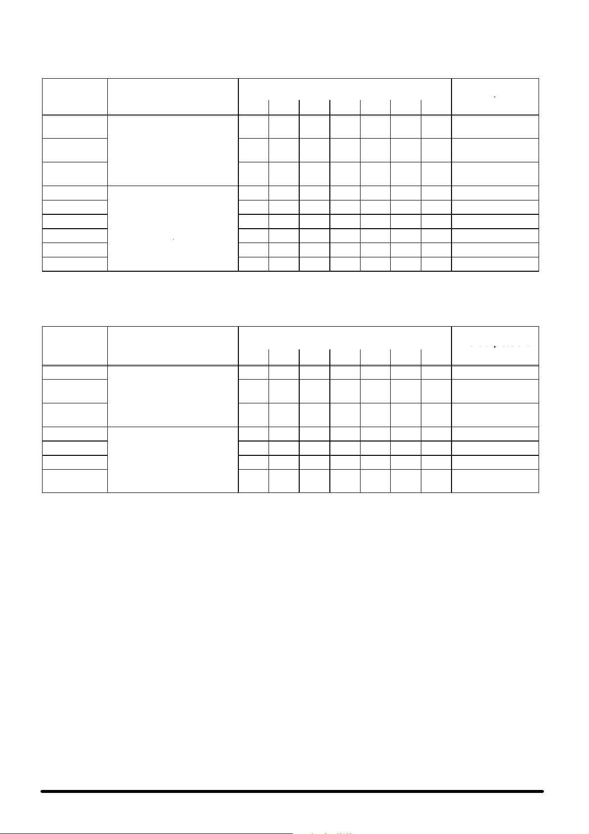
Tab. 2 -- Sound pressure levels -- Livelli pressione sonora
Modello
p
f
A
Ambienteinterno,a2mdifronte
theunit
,
Modello
eodpessoe
A
Ambienteesterno,a2mdifronte
Sound pressure levels, for measurement carried out with standard fan speed regulator (Variex).
Livelli di pressione sonora, per misurazioni eseguite con regolatore di velocità ventilatore (Variex)
Model
Modello
50Hz
SE 05
SE 06
SE 08
SE 10
SE 13
SE 14
SC 05 45 49 49 45 41 38 36 47
SC 06 46 50 50 46 42 39 37 48
SC 08
SC 10
SC 13
SC 14 54 58 59 57 53 49 45 58
Note: Values are referred to an ambient temperature of 35_C.
Nota: I valori sono riferiti ad una temperatura ambiente di 35
Model
60Hz
SE 06 53 57.5 57 53.5 49.5 47 44.5 56
SE 08
SE 10
SE 13
SE 14
SC 06 49.5 53 57 52 49.5 46 42 55
SC 08
SC 10
SC 13
SC 14
Indoor,freefield at 2 m infront o
the unit
mbiente interno, a 2 m difronte
all’unità, campo libero
Outdoor, free field at 2 m in front of
the unit
Ambiente esterno, a 2 m di fronte
all’unità, campo libero
Indoor, free field at 2 m in front of
the unit
mbiente interno, a 2 m difronte
all’unità, campo libero
Outdoor, free field at 2 m in front of
the unit
all’unità, campo libero
63 125 250 500 1000 2000 4000
52 56 50 48 51 49 46 55
55 61 58 56 54 52 51 60
56 61 58 57 55 52 51 62
49 54 54 50 46 43 40 52
51 56 56 52 48 45 43 54
53 57 58 54 51 47 43 56
_
63 125 250 500 1000 2000 4000
60 61 56 54.5 56 54.5 52 61
63 60.5 57.5 59 60 59 56 65
57.5 62.5 57.5 54.5 50 49 44 57
53.5 58 61 57 52 50.5 46 59
54.5 59 64 61.5 57.5 53 48.5 63
Octave band frequency (Hz)
Frequenza di banda d’ottava (Hz)
C.
Octave band frequency (Hz)
Frequenza di banda d’ottava (Hz)
Sound pressure level
Livello di pressione
sonora
[dB(A)]
Sound pressure level
Livello di pressione
sonora
[dB(A)]
12
Page 73
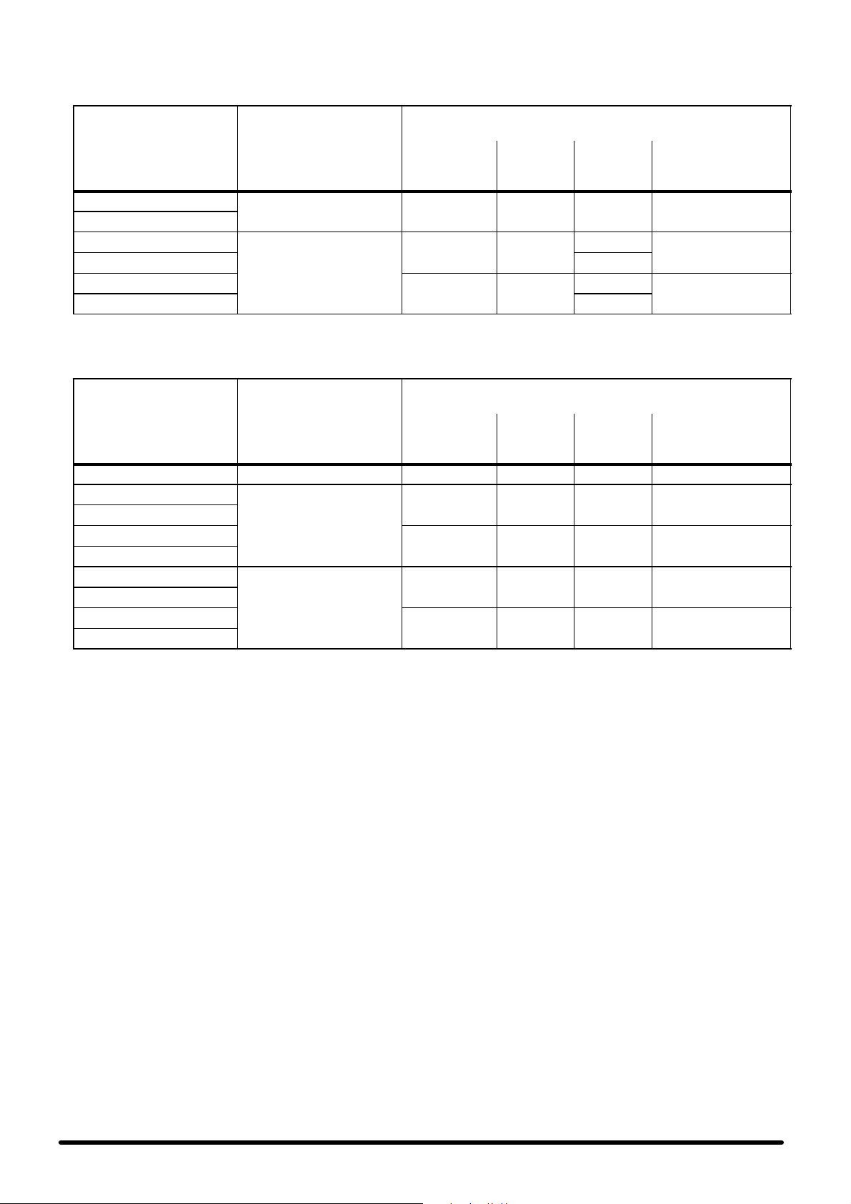
Tab. 3 -- Electrical characteristics -- evaporating unit (internal)
Caratteristiche elettriche -- unità evaporante (interna)
50 Hz
MODEL
MODELLO
Hisp SE05
Hisp SE06
Hisp SE08
Hisp SE10
Hisp SE13
Hisp SE14
Power supply
Alimentazione elettrica
230/1/50 1.1 1.2 1.75 0.2
400/3/50
OA
[A]
3.20 5
2.5x2 3.6x2
60 Hz
MODEL
MODELLO
Hisp SE06 230/1/60 1.4 1.6 2.1 0.32
Hisp SE08
Hisp SE10
Hisp SE13
Hisp SE14
Hisp SE08
Hisp SE10
Hisp SE13
Hisp SE14
NOTE:
The OA fan is referred to a standard unit operating at standard pressure drop.
Power supply
Alimentazione elettrica
230/3/60
460/3/60
OA
[A]
3.8 4.5 6.1 0.82
2x3.4 2x5 2x8.0 2x0.8
3.8 4.5 6.1 0.82
2x3.4 2x5 2x8.0 2x0.8
EVAPORATOR FAN
VENTILATORE EVAPORATORE
FLA
[A]
EVAPORATOR FAN
VENTILATORE EVAPORATORE
FLA
[A]
LRA
[A]
---
---
---
---
LRA
[A]
Absorbed power
Potenza assorbita
(kW)
0.7
0.6x2
Absorbed power
Potenza assorbita
(kW)
NOTA:
L’OA del ventilatore si riferisce al funzionamento stdandard dell’unità alla perdita di carico standard.
13
Page 74

Tab. 4 -- Electrical characteristics -- motor condensing unit (external)
1.11.252.70.2
6
6
Caratteristiche elettriche -- unita’ motocondensante (esterna)
50 Hz
CONDENSER FAN
VENTILATORE CONDENSATORE
MODEL
MODELLO
Hisp SC05
Hisp SC06
Hisp SC08 3.2 4.8 31 1.7
Hisp SC10
Hisp SC13
Hisp SC14 3.4 3.5 7.4 0.8 8.0 12.4 65 4.3
Power supply
Alimentazione elettrica
230/1/50 0.8 1.2 1.4 0.18
400/3/50
OA
FLA
[A]
1.1 1.25 2.7 0.26
[A]
LRA
[A]
Absorbed
power
Potenza
assorbita
(kW)
OA
[A]
5.5 10 35 1.21
7.5 11.4 47 1.62
4.6 6.6 43 2.6
6.2 7.5 51 3.4
COMPRESSOR
COMPRESSORE
FLA
LRA
[A]
[A]
60 Hz
CONDENSER FAN
VENTILATORE CONDENSATORE
MODEL
MODELLO
Hisp SC06 230/1/60 2.4 2.9 7.4 0.54 7.5 11.3 45.0 1.62
Hisp SC08
Hisp SC10
Hisp SC13
Hisp SC14 3.1 3.8 8.0 0.71 12.1 15.5 91.0 4.0
Hisp SC08
Hisp SC10
Hisp SC13
Hisp SC14 3.1 3.8 8.0 0.71 6.3 7.4 50.0 4.0
Power supply
Alimentazione elettrica
230/3/60
460/3/60
OA
FLA
[A]
3.1 3.8 8.0 0.71
3.1 3.8 8.0 0.71 10.6 13.5 88.0 3.4
3.1 3.8 8.0 0.71
3.1 3.8 8.0 0.71 5.3 6.6 44.0 3.4
[A]
LRA
[A]
Absorbed
power
Potenza
assorbita
(kW)
OA
[A]
5.2 7.3 45.0 1.5
8.1 10.9 77.0 2.5
2.8 3.8 22.4 1.6
4.0 5.5 39.0 2.5
COMPRESSOR
COMPRESSORE
FLA
LRA
[A]
[A]
Absorbed
power
Potenza
assorbita
(kW)
Absorbed
power
Potenza
assorbita
(kW)
Tab. 5 -- Electrical characteristics (optional) -- Caratteristiche elettriche (opzionali)
EVAPORATOR FAN 48 Vdc
VENTILATORE EVAP. 48 Vdc
MODEL
MODELLO
Hisp SE05
Hisp SE06
Hisp SE08
Hisp SE10
Hisp SE13
Hisp SE14 300x2 NA NA 7.5 (460/3/60) 6
NOTES:
The electrical heating values are referred to maximum heating (1 step).
NA: Not available at the current time. This feature will be available in the near future: please contact the Technical Support Department
NOTE:
NA: Non disponibile attualmente. Disponibile a breve: contattare l’Ufficio Supporto Tecnico
I valori di riscaldamento elettrico si riferiscono al riscaldamento massimo (1 gradino).
FLA
[A]
3.0x2 70x2 5.8x2 140x2 13.1 3
8.4x2
Absorbed
power
Potenza
assorbita
(W)
170x2 9.6x2 230x2
250x2 NA NA 7.5 (460/3/60)
EVAPORATOR FAN 24 Vdc
VENTILATORE EVAP. 24 Vdc
Absorbed
FLA
[A]
14
power
Potenza
assorbita
(W)
ELECTRIC HEATING
RISCALDAMENTO ELETTRICO
Absorbed
FLA
[A]
8.7 (400/3/50)
15.1 (230/3/60)
power
Potenza
assorbita
(kW)
6
Page 75

Tab. 6 -- Differential current protection switch and cable size, AC supply
()V
g
g
Cooling
()V
g
f
f
f
f
Raffreddamento+
V
g
(24/
)
(24/48Vdc
)
Interruttore di protezione e dimensioe cavi, alimentazione AC
UNIT VERSION (50 Hz)
ERSIONE UNITA’ (50 Hz)
Coolin
Raffreddamento
Cooling + Heating
Raffreddamento +
Riscaldamento
Cooling + Heating
+ Freecooling
Raffreddamento +
Riscaldamento +
Freecooling
UNIT VERSION (60 Hz)
ERSIONE UNITA’ (60 Hz)
Cooling
Ra
reddamento
Raffreddamento +
Riscaldamento
Cooling + Heating
Cooling + Heating
+ Freecooling
Ra
reddamento +
Riscaldamento +
Freecooling
HISP 05--- 06 20 A --- 2x10mm2+Tx10mm
H I S P 0 8 --- 1 0 --- 1 3 --- 1 4 --- 20 A 4x10mm2+Tx10mm
HISP 05--- 06 20 A --- 2x10mm2+Tx10mm
H I S P 0 8 --- 1 0 --- 1 3 --- 1 4 --- 20 A 4x10mm2+Tx10mm
HISP 05--- 06 20 A --- 2x10mm2+Tx10mm
H I S P 0 8 --- 1 0 --- 1 3 --- 1 4 --- 20 A 4x10mm2+Tx10mm
HISP 06 20 A --- --- 2x10mm2+Tx10mm
HISP
0 8 --- 1 0 --- 1 3 --- 1 4
HISP
0 8 --- 1 0 --- 1 3 --- 1 4
HISP 06 20 A --- --- 2x10mm2+Tx10mm
HISP
0 8 --- 1 0 --- 1 3 --- 1 4
HISP
0 8 --- 1 0 --- 1 3 --- 1 4
HISP 06 20 A --- --- 2x10mm2+Tx10mm
HISP
0 8 --- 1 0 --- 1 3 --- 1 4
HISP
0 8 --- 1 0 --- 1 3 --- 1 4
Protection switch with differential current I∆n=0.3A
Interruttore di protezione a corrente diff. I∆n=0.3A
230V / 1 / 50H z 400V / 3 / 50Hz
Interruttore di protezione a corrente differ. I∆n=0.3A
Protection switch with differential current I∆n=0.3A
230V / 1 / 60H z 230V / 3 / 60Hz 460V / 3 / 60Hz
--- 32 A --- 4x16mm2+Tx16mm
--- --- 25 A 4x10mm2+Tx10mm
--- 32 A --- 4x16mm2+Tx16mm
--- --- 25 A 4x10mm2+Tx10mm
--- 32 A --- 4x16mm2+Tx16mm
--- --- 25 A 4x10mm2+Tx10mm
Cable siz ing
Dimensionamento cavo
Cable sizing
Dimensionamento cavo
2
2
2
2
2
2
2
2
2
2
2
2
2
2
2
Tab. 7 -- Main disconnector switch and cable size, DC supply
Interruttore di sezionamento e dimensione cavi, alimentazione DC
UNIT VERSION
ERSIONE UNITA’
Emergency cooling
48 Vdc
Raffreddamento di
emergenza (24/48Vdc)
HISP 05--- 06 10 A 16 A 2x2.5mm
H I S P 0 8 --- 1 0 --- 1 3 --- 1 4 20 A 32 A 2x4mm
(*) With emergency cooling 48 Vdc option
(**) With emergency cooling 24 Vdc option
(*) Con opzione di raffreddamento d’emergenza a 48 V dc
(**) Con opzione di raffreddamento d’emergenza a 24 V dc
48 Vdc (*) 24 Vdc (**)
Switch
Interruttore
Cable sizing
Dimensionamento cavo
2
2
15
Page 76
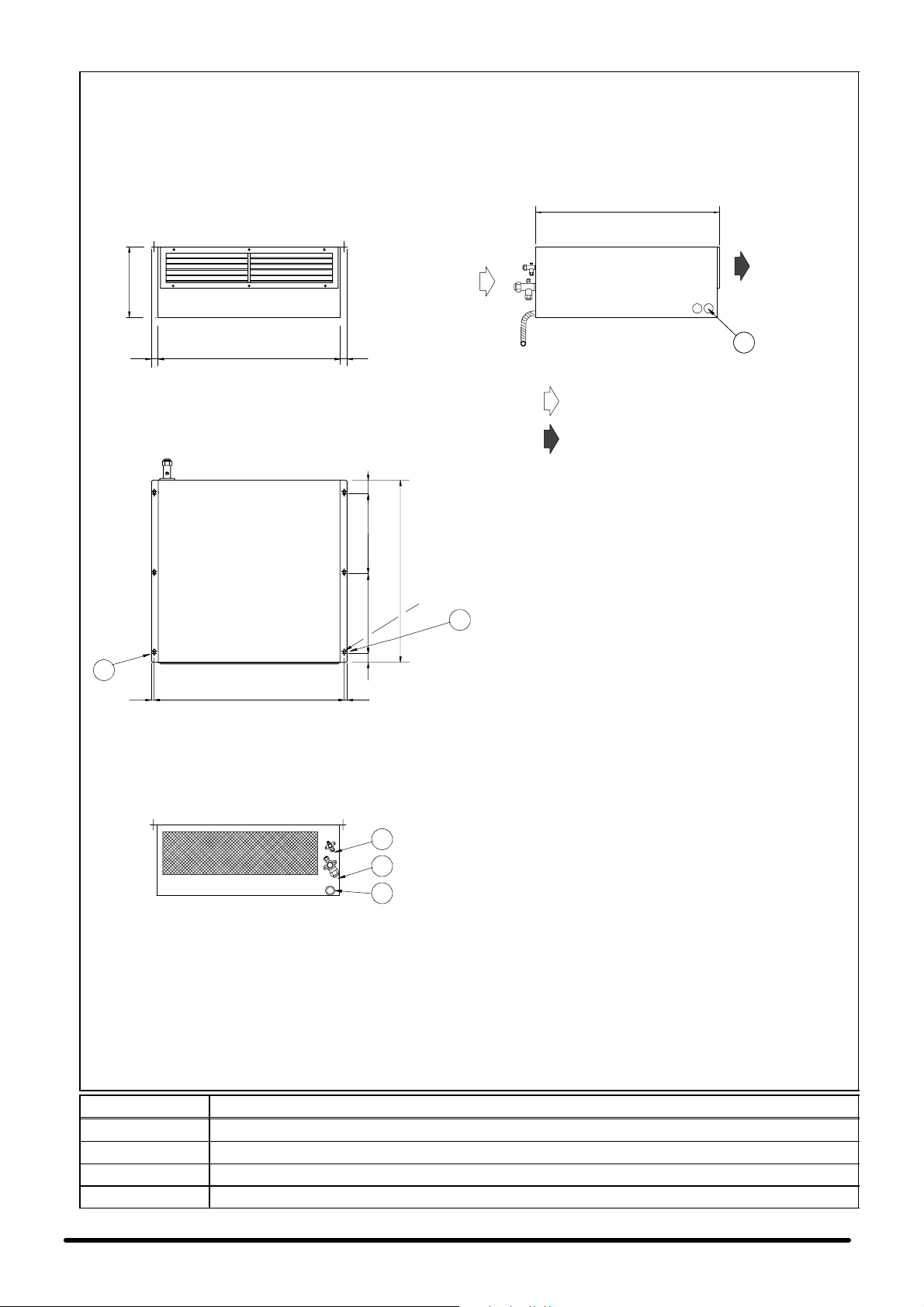
F i g . 1 --- O v e r a l l di m e n s i o n s --- D i m e n s i o n i d i i n g o m b r o
Fig. 1a --- Evaporator version without freecooling SE 05---06
Unità evaporante versione senza freecooling SE 05 ---06
F R O N T V I E W --- V I S T A F R O N T A L E
310
80029 29
TOP VIEW --- VISTA DALL’ALTO
SIDE VIEW --- VISTA LATERALE
800
E
E
air return --- ripresa aria
conditioned air --- aria trattata
350 6035040
800
N . 6 H O L E S --- FO R I ø 8
E
E
12
834 12
REAR VIEW --- VISTA POSTERIORE
I
U
S
POS. Description --- Descrizioni
E Electrical connections --- Collegamenti elettrici
S Condensate drain --- Scarico condensa
U Refrigerant outlet --- Uscita refrigerante
I Refrigerant inlet --- Ingresso refrigerante
1
Page 77

Fig. 1b --- Evaporator version with freecooling SE 05 ---06
Unità evaporante versione con freecooling SE 05 ---06
F R O N T V I E W --- V I S T A F R O N T A L E
310
80029 29
TOP VIEW --- VISTA DALL’ALTO
SIDE VIEW --- VISTA LATERALE
1050
E
inlet air return --- ripresa aria interna
conditioned air --- aria trattata
250800
350 6035040
freecooling air --- aria di freecooling
E
834 1212
REAR VIEW --- VISTA POSTERIORE
Circular ducts version --- Versione con collari circolari
N.2 COLLARS 4 200 HEIGHT 35 mm
N.2 COLLARI 4 200 ALTEZZA 35 mm
310
185 125
220 300 280
N . 6 H O LES --- F O R I 4 8
E
REAR VIEW --- VISTA POSTERIORE
Rectangular duct version --- Versione con collare rettangolare
COLLAR 190 X 560 HEIGHT 35 mm
COLLARE 190 X 560 ALTEZZA 35 mm
I
U
S
310
90 190 30
90 560 150
I
U
S
POS. Description --- Descrizioni
E Electrical connections --- Collegamenti elettrici
S Condensate drain --- Scarico condensa
U Refrigerant outlet --- Uscita refrigerante
I Refrigerant inlet --- Ingresso refrigerante
2
Page 78

Fig. 1c --- Condensing unit --- Unità condensante SC 05 ---06
SIDE VIEW --- VISTA LATERALE
285
190 4042
N. 2+2 SQUARE CAGED NUTS M6
REAR VIEW --- VISTA POSTERIORE
F R O N T V I E W --- V I S T A F R O N T A L E
15
770
N. 2+2 SQUARE CAGED NUTS M6
800
TOP VIEW --- VISTA DALL’ALTO
AIR FLOW
FLUSSO ARIA
537
15
U
I
E
POS. Description --- Descrizioni
E Electrical connections --- Collegamenti elettrici
U Refrigerant outlet --- Uscita refrigerante
I Refrigerant inlet --- Ingresso refrigerante
AIR FLOW
FLUSSO ARIA
3
Page 79

F i g . 1 d --- E v a p o r a t o r v e r s i o n w i t h o u t f r e e c o o l i n g S E 0 8 --- 1 0 --- 1 3 --- 1 4
U n i t à e v a p o r a n t e v e r s i o n e s e n z a f r e e c o o l i n g S E 0 8 --- 1 0 --- 1 3 --- 1 4
F R O N T V I E W --- V I S T A F R O N T A L E
395
105530 30
TOP VIEW --- VISTA DALL’ALTO
320
320 9032050
1100
N.6 HOLES ø8
N.6 FORI ø8
SIDE VIEW --- VISTA LATERALE
1100
air return --- ripresa aria
conditioned air --- aria trattata
E
E
E
12
1086 12
E
REAR VIEW --- VISTA POSTERIORE
U
395
I
S
POS. Description --- Descrizioni
E Electrical connections --- Collegamenti elettrici
S Condensate drain --- Scarico condensa
U Refrigerant outlet --- Uscita refrigerante
I Refrigerant inlet --- Ingresso refrigerante
4
Page 80

F i g . 1 e --- Ev a p o r a t o r v e r s i o n w i t h f r e e c o o l i n g S E 0 8 --- 1 0 --- 1 3 --- 1 4
U n i t à e v a p o r a n t e v e r s i o n e c o n f r e e c o o l i n g S E 0 8 --- 1 0 --- 1 3 --- 1 4
F R O N T V I E W --- V I S T A F R O N T A L E
395
105530 30
TOP VIEW --- VISTA DALL’ALTO
320 90320 320
295
1100
SIDE VIEW --- VISTA LATERALE
1395
E
inlet air return --- ripresa aria interna
conditioned air --- aria trattata
freecooling air --- aria di freecooling
N . 6 H O LES --- F O R I 4 8
E
E
REAR VIEW --- VISTA POSTERIORE
Circular ducts version --- Versione con collari circolari
N.2 COLLARS 4 250 HEIGHT 35 mm
N.2 COLLARI 4 250 ALTEZZA 35 mm
50
REAR VIEW --- VISTA POSTERIORE
Rectangular duct version --- Versione con collare rettangolare
U
395
220 175
220 175
I
395
25095 50
S
350 395310
POS. Description --- Descrizioni
E Electrical connections --- Collegamenti elettrici
S Condensate drain --- Scarico condensa
U Refrigerant outlet --- Uscita refrigerante
I Refrigerant inlet --- Ingresso refrigerante
COLLAR 250 X 600 HEIGHT 35 mm
COLLARE 250 X 600 ALTEZZA 35 mm
600 270185
U
I
S
5
Page 81

F i g . 1 f --- C o n d e n s i n g u n i t --- U n i t à c o n d e n s a n t e S C 0 8 --- 1 0 --- 1 3 --- 1 4
SIDE VIEW --- VISTA LATERALE
F R O N T V I E W --- V I S T A F R O N T A L E
1050
REAR VIEW --- VISTA POSTERIORE
690
U
I
500
SIDE VIEW --- VISTA LATERALE
E
TOP VIEW --- VISTA DALL’ALTO
AIR FLOW
FLUSSO ARIA
N. 4 x ø8
AIR FLOW
FLUSSO ARIA
887==
AIR FLOW
FLUSSO ARIA
526
POS. Description --- Descrizioni
E Electrical connections --- Collegamenti elettrici
U Refrigerant outlet --- Uscita refrigerante
I Refrigerant inlet --- Ingresso refrigerante
AIR FLOW
FLUSSO ARIA
6
Page 82

Fig. 2 --- Examples of installation --- Esempi di installazione
Fig. 2a --- Hisp SE with freecooling option --- Hisp SE con opzione freecooling
1
2
6
11
7
8
9
3
5
4
POS. DESCRIPTION --- DESCRIZIONE
Hisp SE with FC option (optional rectangular hole)
1
Hisp SE con opzione FC (foro rettangolare opzionale)
Hisp SE with FC option (standard circular hole)
2
Hisp SE con opzione FC (foro circolare standard)
3 Overpressure damper --- Serranda di sovrapressione 134948 134992
4 Grille for overpressure damper --- Griglia per serranda di sovrapressione 270206 117832
5 Hole in the wall --- Foro a parete 400 x 200 mm 600 x 400 mm
2 FC flexible ducts L=0.5 m, with fixing clamps
6
2 condotti flessibili FC L=0.5 m, con fascette di fissaggio
7 Wall plate for FC circular duct --- Piastra a muro per condotto FC circolare 13503801 13536101
8 Aluminium grille with metallic prefilter --- Griglia in alluminio con prefiltro metallico 270202 270219
9 Metallic prefilter (included in (8) - -- Prefiltro metallico (incluso in (8)
10 Hole in the wall --- Foro a parete 550 x 210 mm 590 x 230 mm
11 Wall plate for FC rectangular duct --- Piastra a muro per condotto FC rettangolare 13501801 13536001
10
CODE --- CODICE
SE+SC
05 ---06
270190 (∅ 202) 270191 (∅ 254)
SE+SC
0 8 --- 1 0 --- 1 3 --- 1 4
7
Page 83

Fig. 2b --- Hisp SE without freecooling option --- Hisp SE senza opzione freecooling
Fig. 3 --- Condenser positioning --- Posizionamento unità condensante
AA
A
Hisp 05 --- 06 H i s p 0 8 --- 1 0 --- 1 3 --- 1 4
250 100
8
Page 84

Fig. 4 --- Wall fixing of condensing unit --- Fissaggio a parete unità motocondensante
1
5
Condensingunitinstallationkit(optional)
1--- screw anchor
tassello nylon
6 --- washer / rondella inox
5 --- s e r r a t e d l o c k w a sh e r
Rosetta dentellata inox
4--- nut / dado inox
4 --- nut / dado inox
5 --- s e r r a t e d l o c k w a sh e r
Rosetta dentellata inox
6 --- washer / rondella inox
2 --- washer / rondella inox
3 --- s c r e w / v i t e i n o x
7 --- a n t i --- v i b r a t i n g m o u n t
supporto antivibrante
8 --- b r a c k e t / m e n s o l a
POS. DESCRIPTION --- DESCRIZIONE
---
---
---
--- 6 --- 7 --- 8
--Kit mensole per installazione unità condensante (optional)
9
---2---3---4---
CODE --- CODICE
SC 05---06 S C 0 8 --- 1 0 --- 1 3 --- 1 4
129160 ---
--- 129161
Page 85

F i g . 5 --- S e r v i c e a r e a --- A r e a d i se r v i z i o
Fig. 5a --- Service area room unit --- Area di servizio unità ambiente
A
CB D
Fig. 5b
Fig. 5c --- Service area condenser
Area di servizio unità
condensante
E
Hisp 05 --- 06
250
H i s p 0 8 --- 1 0 --- 1 3 --- 1 4
100
Hisp SE with freecooling option
(wall installation)
Hisp SE con opzione freecooling
(installazione a parete)
AIR CON DITIONED
ARIA CONDIZIONATA
SIDE
LATO
VERSION WITH FREECOOLING
VERSIONE CON FREECOOLING
VERSION WITHOUT FREECOOLING
VERSIONE SENZA FREECOOLING
200 300 300 0
200 100 0 0
E
500
Hisp SE without freecooling option
(wall installation)
Hisp SE senza opzione freecooling
(installazione a parete)
BC DA
200
AIR CON DITIONED
ARIA CONDIZIONATA
1300 (SE 08 --- 10---13--- 14)
SIDE
LATO
AIR RETURN
RIPRESA ARIA
1050 (SE 05 --- 06)
1395 (SE 08 --- 10---13--- 14))
1550 (SE 05 --- 06)
1895 (SE 08 --- 10---13--- 14)
OUTSIDE AIR
ARIA ESTERNA
min. 500
AIR RETURN
RIPRESA ARIA
800 (SE 05 --- 06)
min. 200
1100 (SE 08 --- 10---13--- 14)
1000 (SE 05 --- 06)
10
Page 86

Fig. 6 --- Electrical c onnecti ons --- Collegamenti elettrici
AC
DC
(optional)
AC power supply / alimentazione elettrica AC
DC power supply (optional) / alimentazione elettrica DC (opzionale)
SCcontrol/ControllounitàSC
Microface display / Display Microface
F i g . 7 --- E l e c t r i c a l di a g r a m SE + S C 0 5 --- 0 6 --- S c h e m a e l e t t r i c o S E + S C 0 5 --- 0 6
SPLIT UNIT -- SE.. + SC.. ELECTRICAL CONNECTIONS
OR Ext. INVERTER 230Vac (optional)
MAINSUPPLY 230Vac
EMERGENCY SUPPLY 24/48Vdc
TO MICROFACE
57 55 057
57 55
56
SHIELDED CABLE 4X1.5 mm
CAVOSCHERMATO 4X1.5 mm
2
2
057
56
U6
A CURA DELL’INSTALLATORE
TO BE DONE BY INSTALLER
U6
N2
CABLE4+PE2.5mm
CAVO4+PE 2.5 mm
2
2
U2
N2
N6
PE
PE
U2N6
SHIELDEDHIROBUS CABLE 8 POLES COD.275635
PE
CAVO HIROBUS8 POLI SCHERMATO COD.275635
PE
402
400 302
401
300
SHIELDED CABLE 7X1 mm2
CAVOSCHERMATO 7X1 mm2
400 402
300
401
TO DISPLAY
OPTIONAL--OPZIONALI
34
301
CAVOSCHERMATO 2X1 mm2
301
34
302
020 1
64
35
65
A CURA DELL’INSTALLATORE
CAVOSCHERMATO 2X1 mm2
SHIELDED CABLE 2X1 mm2
CAVOSCHERMATO 2X1 mm2
SHIELDED CABLE 2X1 mm2
TO BE DONE BY INSTALLER
SHIELDED CABLE 2X1 mm2
G0 G 70
SHIELDED CABLE 3X1 mm2
CAVOSCHERMATO 3X1 mm2
FASTON 6,3 mm
70
G0
020
1
64
35
65
REMOTE SWITCH
ON/OFF
FASTON 6,3 mm
G
G0
Y2
G
OPZIONALE HIROSS CON SCHEDA ALLARMI
OPTIONAL HIROSS WITHALLARM BOARD
SCHEDA ALLARMI (OPZIONALE)
ALLARM BOARD (OPTIONAL)
ON OFF
11
FASTON 6,3 mm
R1R2C2R3C3R4R5
C1
Page 87
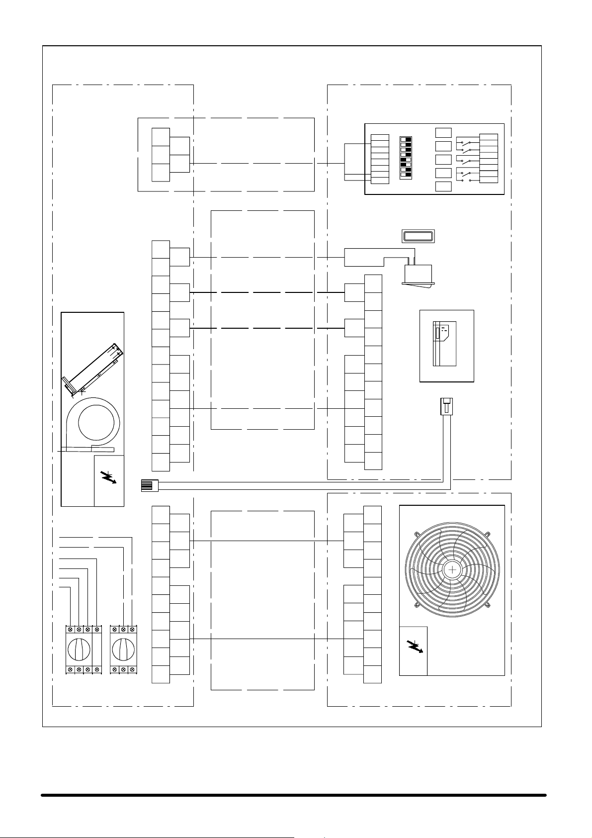
F i g . 7 a --- E l e c t r i c a l d i a g r a m S E + S C 0 8 --- 1 0 --- 1 3 --- 1 4 --- S c h e m a e l e t t r i c o S E + S C 0 8 --- 1 0 --- 1 3 --- 1 4
SPLIT UNIT -- SE.. + SC.. ELECTRICAL CONNECTIONS
SCHEDA ALLARMI (OPZIONALE)
OPTIONAL HIROSS WITHALLARM BOARD
OPZIONALE HIROSS CON SCHEDA ALLARMI
70
SHIELDED CABLE 3X1 mm2
G0 G 70
CAVOSCHERMATO 3X1 mm2
FASTON 6,3 mm
G
G0
ALLARM BOARD (OPTIONAL)
ON OFF
Y2
G
G0
C1
R1
R2
C2
R3
C3
R4
R5
FASTON 6,3 mm
TO MICROFACE
EMERGENCY SUPPLY 24/48Vdc
OR Ext. INVERTER 230Vac (optional)
MAINSUPPLY 400Vac
TO BE DONE BY INSTALLER
A CURA DELL’INSTALLATORE
SHIELDED CABLE 2X1 mm2
020 1
65
64
35
34
OPTIONAL--OPZIONALI
301
300
402
401
400 302
PE
CAVOSCHERMATO 2X1 mm2
SHIELDED CABLE 2X1 mm2
CAVOSCHERMATO 2X1 mm2
SHIELDED CABLE 2X1 mm2
CAVOSCHERMATO 2X1 mm2
SHIELDED CABLE 7X1 mm2
CAVOSCHERMATO 7X1 mm2
1
020
65
64
35
34
302
301
300
401
400 402
PE
ON/OFF
REMOTE SWITCH
FASTON 6,3 mm
TO DISPLAY
CAVO HIROBUS8 POLI SCHERMATO COD.275635
SHIELDEDHIROBUS CABLE 8 POLES COD.275635
057
56
SHIELDED CABLE 4X1.5 mm
CAVOSCHERMATO 4X1.5 mm
2
2
057
56
QS1 QS2
57 55
PE
N2
T2
S2
CABLE5+PE2.5mm
CAVO5+PE 2.5 mm
2
2
R2
R20
TO BE DONE BY INSTALLER
A CURA DELL’INSTALLATORE
57 55
PE
N2
T2
S2
R2
R20
12
Page 88
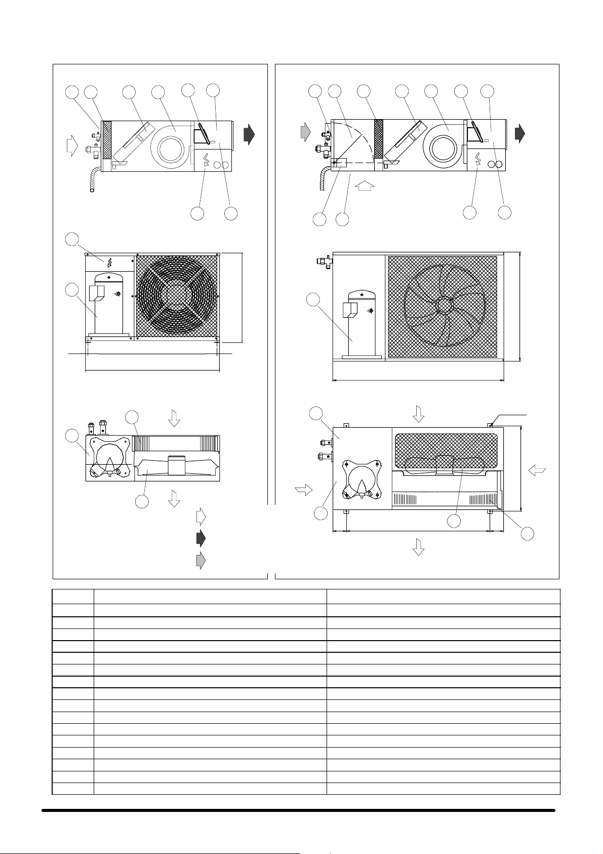
Fig. 8 --- Operation diagram --- Schema di funzionamento
SC 05--06
Unit without freecooling
Unità senza freecooling
13
F R O N T A L V I E W --- V I S T A F R O N T A L E
14
15
SIDE VIEW --- VISTA LATERALE
9
5
431
770
800
6
11 10
SC 08--10--13 --14
SIDE VIEW --- VISTA LATERALE
5 92 438
Unit with freecooling
1
7
Unità con freecooling
F R O N T A L V I E W --- V I S T A F R O N T A L E
537
15
14
1050
6
11
10
690
TOP VIEW --- VISTA DALL’ALTO
16
15
12
AIR FLOW
FLUSSO ARIA
AIR FLOW
FLUSSO ARIA
air return --- ripresa aria
conditioned air --- aria trattata
TOP VIEW --- VISTA DALL’ALTO
13
AIR FLOW
FLUSSO ARIA
15
AIR FLOW
FLUSSO ARIA
887==
12
AIR FLOW
FLUSSO ARIA
N. 4 x ø8
526
outside air --- aria esterna
POS. DESCRIPTION DESCRIZIONE
1 Air return grille Griglia aspirazione aria
2 Freecooling damper (Freecooling version only) Serranda Freecooling (solo versione Freecooling)
3 Air filter Filtro aria
4 Evaporator coil Evaporatore
5 Evaporator unit fan Ventilatore unità evaporante
6 Air discharge duct Canale mandata aria
7 Damper motor (Freecooling version only) Motore serranda (solo versione Freecooling)
8 Air suction grille (Freecooling version only) Griglia ripresa aria di rinnovo (solo versione Freecooling)
9 Electric heaters (optional) Resistenze elettriche (opzionale)
10 Heater safety thermostat (heating version only) Termostato sicurezza resistenze (solo vers. riscaldamento)
11 Electrical panel evaporating unit Quadro elettrico unità evaporante
12 Condenser fan Ventilatore condensatore
13 Electrical panel condensing unit Quadro elettrico unità condensante
14 Refrigeration compressor Compressore
15 Variex Variex
16 Condenser coil Condensatore
AIR
FLOW
FLUSSO
ARIA
16
13
Page 89

Fig. 9 --- Refrigeration connections --- Collegamenti frigoriferi
Hmax=3m
Hmax=3m
F i g . 1 0 --- C o n d e n s a t e d r a i n --- S c a r i c o c o n d e n s a
>30mm
NOTE:
FILL THE DRAIN TRAP WITH WATER BEFORE STARTING UNIT
NOTA:
RIEMPIRE IL SIFONE CON ACQUA PRIMA DI AVVIARE L’IMPIANTO
14
Page 90

Fig. 11 --- Refrigeration circuit --- Schema frigorifero SE+SC 05---06
5
5
SE05+SC05 ø14
SE06+SC06 ø16
1
2
CONNECTION PIPING
TUBAZIONE DI COLLEGAMENTO
INTERNAL UNIT
UNITA’ INTERNA
3
4
5
SE05+SC05 ø8
SE06+SC06 ø8
5
SUPPLY LIMIT --- LIMITE DI FORNITURA
CONNECTION PIPING
TUBAZIONE DI COLLEGAMENTO
SUPPLY LIMIT --- LIMITE DI FORNITURA
12
EV
8
10
LP HP
6
MC
7
11
EXTERNAL UNIT
UNITA’ ESTERNA
9
POS. DESCRIPTION DESCRIZIONE
1 Evaporator fan Ventilatore evaporatore
2 Evaporator Evaporatore
3 Expansion capillary Capillare d’espansione
4 Filter dryer Filtro deidratore
5 Shut---off valve Rubinetto di intercettazione
6 Compressor Compressore
7 Crankcase heating element Resistenza carter
8 Condenser fan Ventilatore condensatore
9 Air cooled condenser Condensatore ad aria
10 Low pressure switch Pressostato bassa pressione
11 High pressure switch Pressostato alta pressione
12 Fan pressure switch control adjuster Regolatore pressostatico del ventilatore
15
Page 91

F i g . 1 2 --- R e f r i g e r a t i o n ci r c u i t --- Sc h e m a fr i g o r i f e r o S E + S C 0 8 --- 1 0 --- 1 3 --- 1 4
1
2
5
SE08+SC08 ø18 CONNECTION PIPING
SE10+SC10 ø18 TUBAZIONE DI COLLEGAMENTO
SE13+SC13 ø22
SE14+SC14 ø22
5
INTERNAL UNIT
UNITA’ INTERNA
3
13
4
14
5
SE08+SC08 ø10 CONNECTION PIPING
SE10+SC10 ø12 TUBAZIONE DI COLLEGAMENTO
SE13+SC13 ø12
SE14+SC14 ø12
5
SUPPLY LIMIT --- LIMITE DI FORNITURA
SUPPLY LIMIT --- LIMITE DI FORNITURA
12
EV
8
10
LP HP
6
MC
7
11
EXTERNAL UNIT
UNITA’ ESTERNA
9
POS. DESCRIPTION DESCRIZIONE
1 Evaporator fan Ventilatore evaporatore
2 Evaporator Evaporatore
3 Thermostatic expansion valve Valvola d’espansione termostatica
4 Filter dryer Filtro deidratore
5 Shut---off valve Rubinetto di intercettazione
6 Compressor Compressore
7 Crankcase heating element Resistenza carter
8 Condenser fan Ventilatore condensatore
9 Air cooled condenser Condensatore ad aria
10 Low pressure switch Pressostato bassa pressione
11 High pressure switch Pressostato alta pressione
12 Fan pressure switch control adjuster Regolatore pressostatico del ventilatore
13 Sight glass Spia di flusso
14 Shut--- off solenoid valve Elettrovalvola intercettazione
16
Page 92

Fig. 13 ---Maintenance example --- Esempio di manutenzione
1
5
2
3
POS. DESCRIPTION DESCRIZIONE
1 Panel for air filter and freecooling section (if installed) Pannello per il filtro aria e la sezione freecooling (se installata)
2 Panel for fan and coil Pannello per il ventilatore e la batteria
3 Panel for electrical panel Pannello per il quadro elettrico
4 Two rows grille, for electrical heating (if installed) Griglia a due ranghi, per riscaldamento elettrico (se installato)
5 Panel for damper motor (freecooling version only) Pannello per il motore della serranda (solo versione freecooling)
4
17
Page 93

Il Fabbricante dichiara che questo prodotto è conforme alle direttive Europee:
The Manufacturer hereby declares that this product conforms to the European Union directives:
Der Hersteller erklärt hiermit, dass dieses Produkt den Anforderungen der Europäischen Richtlinien gerecht wird:
Le Fabricant déclare que ce produit est conforme aux directives Européennes:
El Fabricante declara que este producto es conforme a las directivas Europeas:
O Fabricante declara que este produto está em conformidade com as directivas Europeias:
Tillverkare försäkrar härmed att denna produkt överensstämmer med Europeiska Uniones direktiv:
De Fabrikant verklaart dat dit produkt conform de Europese richtlijnen is:
Vaimistaja vakuuttaa täten, että tämä tuote täyättää seuraavien EU-direktiivien vaatimukset:
Produsent erklærer herved at dette produktet er i samsvar med EU-direktiver:
Fabrikant erklærer herved, at dette produkt opfylder kravene i EU direktiverne:
Since the Liebert HIROSS Company has a policy of continuous
Ο ΚατασÀευαστÞj δηλþνει üτι το παÃüνπÃοΪüνεßναι ÀατασÀευασmÝνο αýmφωνα mετιj οδηγßεj τηj Ε.Ε.:
product improvement, it reserves the right to change design and
specifications without previous notice.
98/37/CE; 89/336/CEE; 73/23/CEE
Printed in Italy by Liebert HIROSS S.p A.
Issued by T.D.Service
Page 94

Zona Industriale Tognana
Via Leonardo da Vinci, 8
35028 Piove di Sacco (PD)
ITALY
Tel. +39 049 9719111
Telefax +39 049 5841257
Internet :
www.liebert-hiross.com
Since the Liebert HIROSS Company has a policy of continuous
product improvement, it reserves the right to change design and
specifications without previous notice.
Liebert HIROSS
is a division of
EMERSON
Printed in Italy by Liebert HIROSS S.p A.
Issued by T.D.Service
 Loading...