

Liebert Hinet 10kVA, Hinet 15kVA, Hinet 20kVA, Hinet 30kVA User Manual
Manual Reference number : 6390001 H - 2 (12/01) Rev ENP Au 07/2002
HHIINNEETT UUPPSS SSYYSSTTEEM
M
1100 –– 3300 kkVVAA 33xx1
1
UUsseerr M
Maannuuaall

(08/01) Page I
This manual describes Hinet Series UPS with the following P.N. :
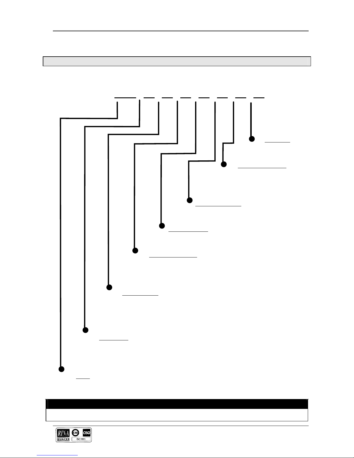
Part Numbering System
HNLCD- XX X X X X X X X
Free Option
0 = No additional option
1 = SNMPE3 card
Insulation Transformer
0 = No Ins. Transformer
1 = Ins. Transf. for 10kVA Unit
2 = Ins. Transf. for 20kVA Unit
3 = Ins. Transf. for 30kVA Unit
Frequency Converter
0 = No Frequency Converter
1 = Frequency Converter
3° Harmonic Filter
0 = No 3° Harmonic Filter
1 = 3° Harmonic Filter
THDi Reduction Filter
0 = No THDi Reduction Filter
1 = THDi filter for 10kVA Unit
2 = THDi filter for 15-20kVA Unit
3 = THDi filter for 30kVA Unit
Internal Batteries
0 = No Internal Battery
1 = 1 Battery String
2 = 2 Battery Strings
3 = 3 Battery Strings
4 = 4 Battery Strings
Output Power
0 = 10kVA
1 = 15kVA
2 = 20kVA
3 = 30kVA
Model
33 = 3 Phase-Input, 3 Phase-Output
31 = 3 Phase-Input, 1 Phase-Output
IMPORTANT
All models in the UPS range are similar in both operation and use.

Hinet UPS System USER MANUAL
Page II (12/01)
Options Part Numbers
OPTIONS (Rev 07/2002)
Description Part Number
Hinet Internal Extended Battery Kit HNINTBATT
Hinet Battery Connecting Kit HNBATTCABLE
Hinet External Battery Cabinet HNBATTCAB
38Ah, 5 Years Batteries for External Battery Cabinet (32 Bloks x 12V ) HN38AH5Y
65Ah, 5 Years Batteries for External Battery Cabinet (32 Bloks x 12V) HN65AH5Y
Hinet Additional Communications Card Kit (Relays) HNRELAYCARD
Hinet Communication SNMP card SNMPE3
Remote Alarm Monitor HNRAM
PLEASE NOTE:
These products are intended for Commercial/Industrial use only, and are not
suitable for use in any life supporting applications.

USER MANUAL Hinet UPS System
(12/01) Page III
IMPORTANT INSTRUCTIONS FOR SAFE USE
? The UPS must be commissioned by a Liebert approved engineer before it is put into service. Failure to observe this
condition will invalidate any implied warranty.
? Do not apply power to this equipment before it has been commissioned by a Liebert approved engineer. This
information is required to substantiate any warranty claims that might be made.
? If you encounter any problems with the procedures contained in this manual you should seek immediate assistance
from the Liebert Sales Office from whom the equipment was purchased. Alternatively, contact the Liebert's Customer
Service & Support department at the address shown below:
Liebert Hiross Service
Customer Service and Support Department
Via Risorgimento 16
20098 S. Giuliano M.se
Milan - Italy
Telephone +39 (0) 298250310
Fax +39 (0) 298250346
This department also arranges service contracts and full commissioning service.
? These units contain no user serviceable parts.
? Due to risk of electrical shock or burn do not attempt to gain internal access
? The UPS is for indoor use only.
It must be protected from rain or excessive moisture and installed in a clean environment, free from flammable liquids,
gasses, or corrosive substances.
Do not put drinks, plants, or any other containers holding liquids, on top of the unit.
? Competent personnel must be consulted if liquid spills into the product.
? Ventilation grills are provided beneath and at the front of the cabinet. Do not block or cover these openings otherwise
overheating may occur and UPS operation become unreliable.
Never insert any object into these ventilation holes or openings.
? Do not place magnetic storage media on top of the unit as it can corrupt the data stored on them.
WARNING
This is a CLASS A Uninterruptible Power Supply (UPS) product. In a domestic environment, this product
may cause radio interference, in which case, the user may be required to take additional measures.
? Storing:
Should the equipment not be installed immediately it must be stored in a room so as to protect it against excessive
humidity (not higher than 90%) and against very high heat sources (not higher than +40°C), and moistureless.
CAUTION: Additionally, make sure that not more than 6 months passed from the time the battery had last been
recharged.
After such period temporarily connect the UPS to mains and activate it for the time required to recharge the batteries.
Hinet UPS System USER MANUAL
Page IV (12/01)
? Batteries:
The following general battery safety precautions and WARNINGS must be observed at all times:
a) Particular attention should be paid to the recommendations concerning local environmental conditions and the
provision of protective clothing, first aid and fire-fighting facilities.
b) A battery can present risk of electric shock or burn from high short circuit currents.
c) When connected in a string the voltage could be 400V d.c.. This voltage is potentially lethal. Always observe high
precautions.
d) Only qualified personnel must install or service batteries.
e) Eye protection must be worn to prevent injury from accidental electrical arcs.
f) Remove rings, watches, necklace’s, bracelets and all metal objects.
g) Only use tools with insulated handles.
h) Wear rubbers gloves and a rubber apron when handling batteries.
i) If a battery leaks electrolyte, or is otherwise physically damaged, it must be placed in a container resistant to
sulphuric acid and disposed of in accordance with local regulations.
j) If electrolyte comes into contact with the skin the affected area must be washed immediately with clean water.
k) Batteries must always be disposed of according to local environmental laws.
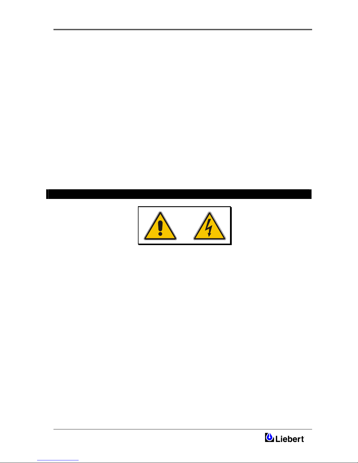
Guide to the Instructions
The warning triangle indicates all the personal safety instructions.
Follow these instructions carefully to avoid injury.

USER MANUAL Hinet UPS System
(12/01) Page V

Hinet UPS System USER MANUAL
Page VI (12/01)
Table of Contents
1 GENERAL DESCRIPTION.......................................................................................................................................... 1
1.1 INTRODUCTION...........................................................................................................................................................1
1.2 EQUIPMENT CONSTRUCTION.......................................................................................................................................1
1.2.1 Principle of operation ...................................................................................................................................... 2
1.2.2 UPS Power Configuration...............................................................................................................................3
1.2.3 Battery fuses switch.......................................................................................................................................... 3
2 INSTALLATION (MECHANICAL) ...........................................................................................................................5
2.1 PRELIMINARY CHECKS ...............................................................................................................................................5
2.1.1 Material admittance......................................................................................................................................... 5
2.1.2 Identification..................................................................................................................................................... 5
2.1.3 Packing material removal................................................................................................................................ 5
2.1.4 Moving the cabinets ......................................................................................................................................... 5
2.1.5 Placing it in the operative position.................................................................................................................. 5
2.1.6 Clearances........................................................................................................................................................6
2.1.7 Raised floor installation................................................................................................................................... 6
2.1.8 Cable entry ....................................................................................................................................................... 6
2.1.9 UPS Mechanical Characteristics.....................................................................................................................6
3 INSTALLATION (ELECTRICAL) .............................................................................................................................7
3.1 POWER CABLING ........................................................................................................................................................7
3.1.1 Power Cable connections................................................................................................................................. 7
3.1.2 Safety earth....................................................................................................................................................... 7
3.1.3 Protective devices.............................................................................................................................................7
3.2 SETTING STANDARD RELAY CARD.............................................................................................................................9
3.2.1 Setting options on the standard Relay Card.................................................................................................... 9
3.2.2 Remote EPO (Emergency Power Off)............................................................................................................10
3.2.3 Emergency Power Off (E.P.O.) push-button connection .............................................................................. 10
3.2.4 Connection to Personal Computer................................................................................................................. 10
3.2.5 UPS Monitoring....................................................................................................................................................11
4 OPERATOR CONTROL PANEL .............................................................................................................................13
4.1 INTRODUCTION.........................................................................................................................................................13
4.2 LCD CONTROL PANEL..............................................................................................................................................14
4.2.1 Control panel indicator LEDs........................................................................................................................ 14
4.2.2 STATUS ALARM MENU................................................................................................................................ 16
4.2.3 COMMAND MODE MENU .......................................................................................................................... 17
4.2.4 EVENT HISTORY MENU.............................................................................................................................. 18
4.2.5 OPERATING LANGUAGE MENU ...............................................................................................................19
4.2.6 CLOCK MENU...............................................................................................................................................19
4.2.7 UPS SETTING MENU...................................................................................................................................19
5 OPERATING INSTRUCTIONS ................................................................................................................................21
5.1 INTRODUCTION.........................................................................................................................................................21
5.2 POWER SWITCHES ....................................................................................................................................................21
5.2.1 UPS Start-Up instructions..............................................................................................................................22
5.2.2 Inverter Turn-on and LCD panel LEDs activation ....................................................................................... 22
5.2.3 Load insertion test.......................................................................................................................................... 22
5.2.4 Hinet UPS switch-off Procedure.................................................................................................................... 23
5.2.5 Manual bypass procedure..............................................................................................................................23
5.2.6 Return from Manual Bypass to normal Operation........................................................................................24
5.2.7 Emergency Power Off (EPO)......................................................................................................................... 24
6 TECHNICAL SPECIFICATION...............................................................................................................................25
7 OPTIONAL EQUIPMENT......................................................................................................................................... 28
7.1 COMMUNICATION CARD KIT (RELAYS)....................................................................................................................28

USER MANUAL Hinet UPS System
(12/01) Page VII
7.2 SNMP CARD............................................................................................................................................................28
7.3 UPGRADE KIT...........................................................................................................................................................28
7.4 ISOLATION TRANSFORMER (INTERNAL OPTION).....................................................................................................28
7.5 INPUT FILTER FOR CURRENT THD REDUCTION (INTERNAL OPTION)......................................................................28
7.6 INPUT 3° HARMONICS FILTER (INTERNAL OPTION) ..................................................................................................28
7.7 INTERNAL EXTENDED BATTERY KIT........................................................................................................................28
7.8 BATTERY CONNECTING KIT .....................................................................................................................................28
7.9 EXTENDED BATTERY CABINET ................................................................................................................................29
7.10 BATTERIES FOR EXTERNAL BATTERY CABINET .......................................................................................................30
7.11 REMOTE ALARM MONITOR......................................................................................................................................31
7.12 FREQUENCY CONVERTER.........................................................................................................................................32
8 LIMITED WARRANTY .............................................................................................................................................33


Hinet UPS User Manual
(12/01) Page 1
1 General Description
1.1 Introduction
This chapter describes the purpose, principle of operation and user controls of the Hinet series on-line Uninterruptible
Power Supply (UPS).
The Hinet series UPS is connected between a critical load, such as a computer, and the mains. Its purpose is to provide
the load with regulated power under all rated load and input supply conditions; i.e. the power provided by the UPS will
be protected from any voltage or frequency variations on the input power supply, or variations in the supply due to
electrical noise, and will continue during periods of input power supply failure. A battery provides a standby power
source for the UPS when the input power supply fails.
1.2 Equipment construction
The equipment is constructed around a steel frame with removable panels. The door can be open to give easy access to
the input, bypass, output, reserve line circuit breakers and battery C.B. fused switch, while protecting them from
accidental operation.
An LCD control panel on the front of the cabinet permits the operator to monitor the UPS.
The cabinet houses both the power components and the batteries.
It is carried on four wheels. Jacking feet help to support the UPS, and also prevent it from moving once it has been
wheeled into its final position. These feet are also used to secure the equipment to its shipping pallet during transit.
Cooling is by internal fan. Air is drawn in from beneath the UPS and exhausted through ventilation grills of the front
panel. These areas must be kept free of anything that may avoid the air flow into and out of the unit.
Figure 1-1 Front view of the Hinet cabinet. Note the location of the Operator control panel
EMERGENCY
Hinet
NORMAL
ALARM
LOAD ON INVERTER
LOAD ON BYPASS
NEXT
BACK
MENU
CLEAR
ENTER

Hinet UPS User Manual
Page 2 (12/01)
1.2.1 Principle of operation
Normal operation
During normal operation, i.e. when the UPS input supply is present and within specification, both the converter and
inverter sections are active and the automatic by-pass is turned on to connect the inverter output to the critical load
terminals. The battery fuse-holder switch is also closed and the battery is therefore permanently float charged at the d.c.
terminals voltage level.
Mains Failure
If the mains has a failure or is out of tolerance the converter will be supplied from the battery, while the inverter will
continue to operate for a period of time which depends on the load and the capacity of the battery. If the mains supply
has not returned within this time, the inverter will go off automatically and an alarm condition will appear on the UPS
operator control panel.
Critical load will not be interrupted in the event of a drop or return of the AC power mains.
Return of power mains
When the mains returns within the required tolerance, the converter will be automatically supplied from mains,
supplying power to the inverter and recharging the battery at the same time. There will be no interruption of the critical
load.
UPS fault
In the event of an inverter failure, the automatic by-pass will automatically transfer the load onto the mains with no
interruption. In such an event, request qualified technical assistance.
The load will be transferred with no interruption if the inverter is synchronised with the mains; if this is not the case,
there will be an interruption of some milliseconds.
The intervention of the automatic by-pass line is shown on the front panel by the yellow led on.
WARNING
CAUTION: When the load is being supplied from the bypass line through the automatic bypass, it is connected
directly to the mains supply and is therefore no longer protected against main faults.
Maintenance Bypass
A second bypass circuit contained in the UPS cabinet, identified as the ‘Maintenance Bypass’ line is included to enable
the reserve supply to be made available to the load while facilitating a safe working environment for carrying out
scheduled UPS system maintenance or trouble shooting. The circuit is manually selected by the Manual Bypass Switch
(3) which can be padlocked in the OFF position.
WARNING
CAUTION: If an automatic circuit breaker device is not present in the input distribution panel, there remains a
dangerous voltage at the output terminals and also on the input terminals of the UPS module that is switched off.
Note: The load is not protected from main aberrations when operating on the maintenance bypass mode .

Hinet UPS User Manual
(12/01) Page 3
Figure 1-2 Hinet’s “Common Bypass” configuration
LEGENDA
?
INPUT MAINS SWITCH
?
RESERVE LINE SWITCH (Bypass)
?
MAINTENANCE BYPASS SWITCH
?
UPS OUTPUT SWITCH
?
BATTERY FUSES SWITCH
?
STEP-UP CONVERTER
?
INVERTER
?
AUTOMATIC BYPASS
?
BATTERY
??
EXTERNAL BATTERY PLUG
These links must be removed for split bypass
1.2.2 UPS Power Configuration
Figure 1-2 illustrates the Hinet UPS in what is known as the “Common Bypass” configuration. In the “Split Bypass”
configuration the static bypass line is connected by a separate power switch to a dedicated `bypass' power source that
also feeds the maintenance bypass line. Where a separate power source is not available the Reserve and Converter input
supply connections would be linked together.
With the exception of the maintenance bypass switch (3), all the isolators shown must be closed during normal UPS
operation.
1.2.3 Battery fuses switch
The battery is connected to the d.c. bus through a battery fuses switch (5) fitted inside the UPS cabinet.
Output
Input
UPS
 Loading...