

Liebert Hiflex, Hiflex Series Product Documentation
Hiflex
Product Documentation
English
cod. 272055 - rev. 24.07.2002


Hiflex
INDEX
1 -The serie 1. . . . . . . . . . . . . . . . . . . . . . . . . . . . . . . . . . . . . . . . . . . . . . . . . . . . . . . . . . . . . . . . . . . . .
1.1 - Unit coding 1. . . . . . . . . . . . . . . . . . . . . . . . . . . . . . . . . . . . . . . . . . . . . . . . . . . . . . . . . . . . . . . . . . . . . . . . . . . .
1.2 - Main features and advantages 1. . . . . . . . . . . . . . . . . . . . . . . . . . . . . . . . . . . . . . . . . . . . . . . . . . . . . . . . . . .
2 -Configuration 2. . . . . . . . . . . . . . . . . . . . . . . . . . . . . . . . . . . . . . . . . . . . . . . . . . . . . . . . . . . . . . . . .
2.1 - Version A 2. . . . . . . . . . . . . . . . . . . . . . . . . . . . . . . . . . . . . . . . . . . . . . . . . . . . . . . . . . . . . . . . . . . . . . . . . . . . . .
2.2 - Version W 3. . . . . . . . . . . . . . . . . . . . . . . . . . . . . . . . . . . . . . . . . . . . . . . . . . . . . . . . . . . . . . . . . . . . . . . . . . . . .
2.3 - Version D 4. . . . . . . . . . . . . . . . . . . . . . . . . . . . . . . . . . . . . . . . . . . . . . . . . . . . . . . . . . . . . . . . . . . . . . . . . . . . .
2.4 - Version H 5. . . . . . . . . . . . . . . . . . . . . . . . . . . . . . . . . . . . . . . . . . . . . . . . . . . . . . . . . . . . . . . . . . . . . . . . . . . . .
2.5 - Version F 6. . . . . . . . . . . . . . . . . . . . . . . . . . . . . . . . . . . . . . . . . . . . . . . . . . . . . . . . . . . . . . . . . . . . . . . . . . . . . .
2.6 - Version C 7. . . . . . . . . . . . . . . . . . . . . . . . . . . . . . . . . . . . . . . . . . . . . . . . . . . . . . . . . . . . . . . . . . . . . . . . . . . . .
2.7 - Hiflex Constant versione A 7. . . . . . . . . . . . . . . . . . . . . . . . . . . . . . . . . . . . . . . . . . . . . . . . . . . . . . . . . . . . . . .
2.8 - Hiflex Constant versione W 7. . . . . . . . . . . . . . . . . . . . . . . . . . . . . . . . . . . . . . . . . . . . . . . . . . . . . . . . . . . . . .
2.9 - Air control 9. . . . . . . . . . . . . . . . . . . . . . . . . . . . . . . . . . . . . . . . . . . . . . . . . . . . . . . . . . . . . . . . . . . . . . . . . . . . .
2.10 -Dimensions and accessibility 9. . . . . . . . . . . . . . . . . . . . . . . . . . . . . . . . . . . . . . . . . . . . . . . . . . . . . . . . . . . .
3 -Operating limits 10. . . . . . . . . . . . . . . . . . . . . . . . . . . . . . . . . . . . . . . . . . . . . . . . . . . . . . . . . . . . . .
4 -Component features 11. . . . . . . . . . . . . . . . . . . . . . . . . . . . . . . . . . . . . . . . . . . . . . . . . . . . . . . . . .
4.1 - Fan 11. . . . . . . . . . . . . . . . . . . . . . . . . . . . . . . . . . . . . . . . . . . . . . . . . . . . . . . . . . . . . . . . . . . . . . . . . . . . . . . . . .
4.2 - Compressor 11. . . . . . . . . . . . . . . . . . . . . . . . . . . . . . . . . . . . . . . . . . . . . . . . . . . . . . . . . . . . . . . . . . . . . . . . . .
4.3 - Coils 11. . . . . . . . . . . . . . . . . . . . . . . . . . . . . . . . . . . . . . . . . . . . . . . . . . . . . . . . . . . . . . . . . . . . . . . . . . . . . . . . .
4.4 - Frame and panels 11. . . . . . . . . . . . . . . . . . . . . . . . . . . . . . . . . . . . . . . . . . . . . . . . . . . . . . . . . . . . . . . . . . . . .
4.5 - Filters 12. . . . . . . . . . . . . . . . . . . . . . . . . . . . . . . . . . . . . . . . . . . . . . . . . . . . . . . . . . . . . . . . . . . . . . . . . . . . . . . .
4.6 - Refrigerants 12. . . . . . . . . . . . . . . . . . . . . . . . . . . . . . . . . . . . . . . . . . . . . . . . . . . . . . . . . . . . . . . . . . . . . . . . . .
4.7 - Electric board 12. . . . . . . . . . . . . . . . . . . . . . . . . . . . . . . . . . . . . . . . . . . . . . . . . . . . . . . . . . . . . . . . . . . . . . . . .
4.8 - Accessibility 12. . . . . . . . . . . . . . . . . . . . . . . . . . . . . . . . . . . . . . . . . . . . . . . . . . . . . . . . . . . . . . . . . . . . . . . . . .
4.9 - Control system 12. . . . . . . . . . . . . . . . . . . . . . . . . . . . . . . . . . . . . . . . . . . . . . . . . . . . . . . . . . . . . . . . . . . . . . . .
4.10 -Packing 13. . . . . . . . . . . . . . . . . . . . . . . . . . . . . . . . . . . . . . . . . . . . . . . . . . . . . . . . . . . . . . . . . . . . . . . . . . . . . .
4.11 -Product quality and safety 13. . . . . . . . . . . . . . . . . . . . . . . . . . . . . . . . . . . . . . . . . . . . . . . . . . . . . . . . . . . . . .
5 -Condensing section 14. . . . . . . . . . . . . . . . . . . . . . . . . . . . . . . . . . . . . . . . . . . . . . . . . . . . . . . . . .
5.1 - Air condensers 14. . . . . . . . . . . . . . . . . . . . . . . . . . . . . . . . . . . . . . . . . . . . . . . . . . . . . . . . . . . . . . . . . . . . . . . .
5.2 - Water condensers. 17. . . . . . . . . . . . . . . . . . . . . . . . . . . . . . . . . . . . . . . . . . . . . . . . . . . . . . . . . . . . . . . . . . . .
5.3 - Dry coolers 17. . . . . . . . . . . . . . . . . . . . . . . . . . . . . . . . . . . . . . . . . . . . . . . . . . . . . . . . . . . . . . . . . . . . . . . . . . .
6 -Technical remarks 20. . . . . . . . . . . . . . . . . . . . . . . . . . . . . . . . . . . . . . . . . . . . . . . . . . . . . . . . . . . .
6.1 - Fluid R407C. 20. . . . . . . . . . . . . . . . . . . . . . . . . . . . . . . . . . . . . . . . . . . . . . . . . . . . . . . . . . . . . . . . . . . . . . . . . .
7 -Electrical characteristics 22. . . . . . . . . . . . . . . . . . . . . . . . . . . . . . . . . . . . . . . . . . . . . . . . . . . . . .
8 -Aeraulic features 27. . . . . . . . . . . . . . . . . . . . . . . . . . . . . . . . . . . . . . . . . . . . . . . . . . . . . . . . . . . . .
8.1 - Useful available heads 27. . . . . . . . . . . . . . . . . . . . . . . . . . . . . . . . . . . . . . . . . . . . . . . . . . . . . . . . . . . . . . . . .
9 -Sound Pressure Level 30. . . . . . . . . . . . . . . . . . . . . . . . . . . . . . . . . . . . . . . . . . . . . . . . . . . . . . . .
9.1 - Sound emission spectra 30. . . . . . . . . . . . . . . . . . . . . . . . . . . . . . . . . . . . . . . . . . . . . . . . . . . . . . . . . . . . . . .
10 -Technical data and performances 35. . . . . . . . . . . . . . . . . . . . . . . . . . . . . . . . . . . . . . . . . . . . . .
11 -Optional 91. . . . . . . . . . . . . . . . . . . . . . . . . . . . . . . . . . . . . . . . . . . . . . . . . . . . . . . . . . . . . . . . . . . . .
11.1 -Filters 91. . . . . . . . . . . . . . . . . . . . . . . . . . . . . . . . . . . . . . . . . . . . . . . . . . . . . . . . . . . . . . . . . . . . . . . . . . . . . . . .
11.2 -HP-FAN 93. . . . . . . . . . . . . . . . . . . . . . . . . . . . . . . . . . . . . . . . . . . . . . . . . . . . . . . . . . . . . . . . . . . . . . . . . . . . .
11.3 -Reheating and humidity control (optional) 96. . . . . . . . . . . . . . . . . . . . . . . . . . . . . . . . . . . . . . . . . . . . . . . .
11.4 -Humidification and dehumidification system 103. . . . . . . . . . . . . . . . . . . . . . . . . . . . . . . . . . . . . . . . . . . . .
11.5 -Water control valve (models W/H) 104. . . . . . . . . . . . . . . . . . . . . . . . . . . . . . . . . . . . . . . . . . . . . . . . . . . . . .
11.6 -Flooding alarm (Liquistat) 104. . . . . . . . . . . . . . . . . . . . . . . . . . . . . . . . . . . . . . . . . . . . . . . . . . . . . . . . . . . . .
11.7 -Smoke alarm (Smokestat) 104. . . . . . . . . . . . . . . . . . . . . . . . . . . . . . . . . . . . . . . . . . . . . . . . . . . . . . . . . . . . .
11.8 -Fire alarm (Firestat) 104. . . . . . . . . . . . . . . . . . . . . . . . . . . . . . . . . . . . . . . . . . . . . . . . . . . . . . . . . . . . . . . . . . .
English

11.9 - Fresh air 105. . . . . . . . . . . . . . . . . . . . . . . . . . . . . . . . . . . . . . . . . . . . . . . . . . . . . . . . . . . . . . . . . . . . . . . . . . . .
11.10 -Suction and delivery ducts 105. . . . . . . . . . . . . . . . . . . . . . . . . . . . . . . . . . . . . . . . . . . . . . . . . . . . . . . . . . . .
11.11 -Deadening cartridges for delivery channels - Silent Carts (models Over) 106. . . . . . . . . . . . . . . . . . .
11.12 -Delivery plenum with horizontal throw (models Over) 107. . . . . . . . . . . . . . . . . . . . . . . . . . . . . . . . . . . .
11.13 -Grid with one deflection rank (models Over) 107. . . . . . . . . . . . . . . . . . . . . . . . . . . . . . . . . . . . . . . . . . . . .
11.14 -Base-frames: models TBD 107. . . . . . . . . . . . . . . . . . . . . . . . . . . . . . . . . . . . . . . . . . . . . . . . . . . . . . . . . . . .
11.15 -Base-modules (models Over) 107. . . . . . . . . . . . . . . . . . . . . . . . . . . . . . . . . . . . . . . . . . . . . . . . . . . . . . . . .
11.16 -Automatic condensate drain pump 107. . . . . . . . . . . . . . . . . . . . . . . . . . . . . . . . . . . . . . . . . . . . . . . . . . . . .
11.17 -Non-return valve (models A and D) 108. . . . . . . . . . . . . . . . . . . . . . . . . . . . . . . . . . . . . . . . . . . . . . . . . . . .
11.18 -Additional temperature and humidity sensor (EEAP) 108. . . . . . . . . . . . . . . . . . . . . . . . . . . . . . . . . . . . . .
11.19 -Microprocessor control with graphic display HIROMATIC G 108. . . . . . . . . . . . . . . . . . . . . . . . . . . . . . . .
11.20 -Deadening insulation coating 109. . . . . . . . . . . . . . . . . . . . . . . . . . . . . . . . . . . . . . . . . . . . . . . . . . . . . . . . . .
11.21 -Duct with deadening insulation coating 109. . . . . . . . . . . . . . . . . . . . . . . . . . . . . . . . . . . . . . . . . . . . . . . . .
11.22 -Power supply at 230/3/50 110. . . . . . . . . . . . . . . . . . . . . . . . . . . . . . . . . . . . . . . . . . . . . . . . . . . . . . . . . . . . .
11.23 -Special packing 110. . . . . . . . . . . . . . . . . . . . . . . . . . . . . . . . . . . . . . . . . . . . . . . . . . . . . . . . . . . . . . . . . . . . . .
11.24 -Air intake from the bottom (models Over) 110. . . . . . . . . . . . . . . . . . . . . . . . . . . . . . . . . . . . . . . . . . . . . . . .
11.25 -Accessory combination 110. . . . . . . . . . . . . . . . . . . . . . . . . . . . . . . . . . . . . . . . . . . . . . . . . . . . . . . . . . . . . . .
12 -Overall dimensions 111. . . . . . . . . . . . . . . . . . . . . . . . . . . . . . . . . . . . . . . . . . . . . . . . . . . . . . . . . .
Hiflex
The HIFLEX Product Documentation can also be surfed on the Web at the address: www.HIROSS.IT/pde/TDS/Hiflex
This document is password-protected. Ask for the password to your Dealer/Area Manager.
English

1 - The serie
HIFLEX is the new series of air conditioners developed by Liebert HIROSS to allow maximum flexibility
of application in technological environments, from data processing centers to manned control rooms and
electronic centers for telecommunication. This series includes units with a rated cooling capacity ranging
from 5 to 40 kW.
1.1 - Unit coding
A mark with four alphanumeric characters identifies the model.
Hiflex
4LOA
is the numeric value
identifying the size of
the unit (4-6-8-)
Models 5-7-9 are
double.
M Small type - R22
S Small size - R22
L Large size - R22
P Small size - R407C
G Large size - R407C
U underfloor air flow (Under)
O upward air flow (Over)
C constant
1.2 - Main features and advantages
The air conditioners of HIFLEX series have the following features:
High sensible cooling capacity; high EER (Energy Efficiency Ratio)
Total front accessibility for the maintenance
Low acoustic emission
Exact electronic control by microprocessor
Small plant dimensions
A Direct expansion unit with external air
cooled condenser
C Chilled water unit
D Direct expansion unit and chilled water
unit (DUALFLUID) with external air
cooled condenser
F Direct expansion unit and chilled water
unit (FREECOOLER) with water cooled
condenser - one water circuit.
H Direct expansion unit and chilled water
unit (DUALFLUID) with water cooled
condenser
W Direct expansion unit with water cooled
condenser
English
1All Versions
Hiflex
2 - Configuration
Here is a short description of the peculiar features of each of the six available versions.
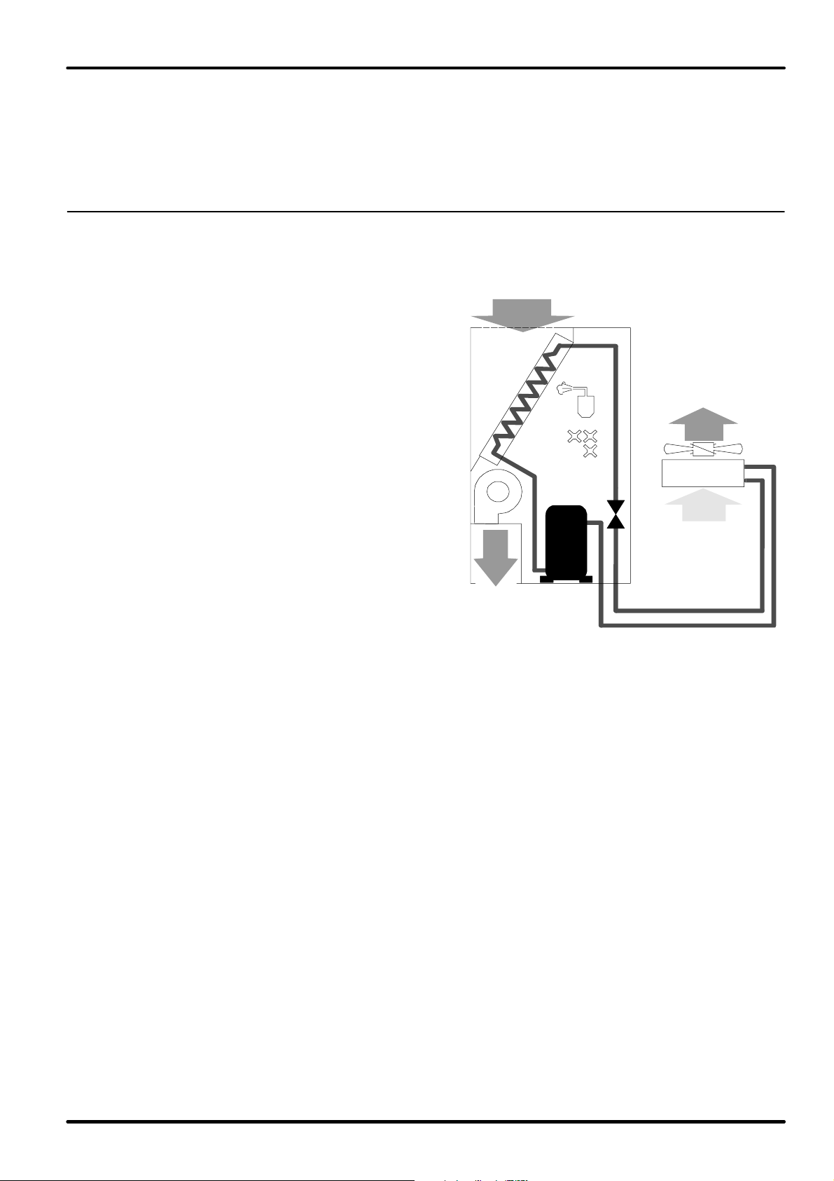
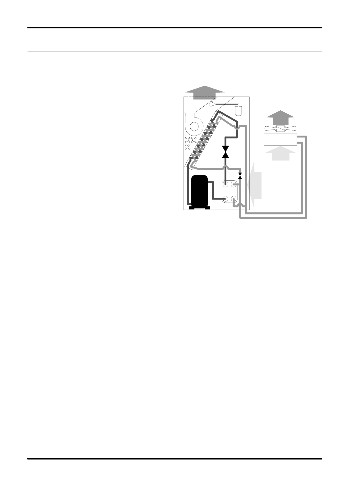
2.1 - Version A
Refrigerating circuit
The 4-6-8 models are provided with a
single refrigerating circuit, the units
5-7-9 have two refrigerating circuits. The
refrigerating circuit includes the compres
sor and the thermal expansion valve with an
external equalizer (or in the M version, the
cappilary) controlling the refrigerant flow to
the evaporator so as to keep a steady over
heating degree. Before the thermal expan
sion valve there is a sight glass enabling
the visual check of the refrigerant charge. A
dryer filter is installed in the liquid line for
better cleaning and less humidity in the cir
cuit. The welded steel liquid receiver is
available in the refrigerating circuit to en
able the constant and even refrigerant flow
to the expansion valve. On-off valves are
installed as standard to help the extraordi
nary maintenance of the circuits.
For a safe operation, during the start-up it
is advisable to install the non-return valve
(supplied as optional on request) on the
connection of the refrigerant with the exter
nal condenser to protect the compressor
from unexpected refrigerant migrations
(see installation diagramme). A suitably sized safety valve is installed on the liquid receiver; the valve is
equipped with flanged connections to allow the refrigerant to be discharged outside through suitable
pipes. All low temperature parts of the refrigerating circuit are insulated. The refrigerating circuit is also
provided with a high pressure switch and a low pressure switch. The low pressure switch has automatic
resetting, whereas - for safety reasons due to possible high pressure in the compressor - the high pres
sure switch has manual resetting. The pressure switch calibration values are shown in the installation
manual supplied with the machine.
The units are supplied without the external condenser and with nitrogen-pressed refrigerating circuit. The
customer himself has to make the connection with the external condenser and the refrigerant charging.
All the instructions for the necessary operations are contained in the installation manual.
Direct expansion air-condensed units
External condensing unit
The units are coupled with the air condensers of Liebert HIROSS wide range in the versions with stan
dard axial fans and with low noise axial fans.For technical data and performances refer to the relevant tech
nical documentation.The following paragraphs describe the suggested couplings for the HIFLEX units as
a function of the outdoor air temperature. The data given below are approximate and must always be veri
fied on the basis of the specific performances and working conditions required.
2 All Versions
English
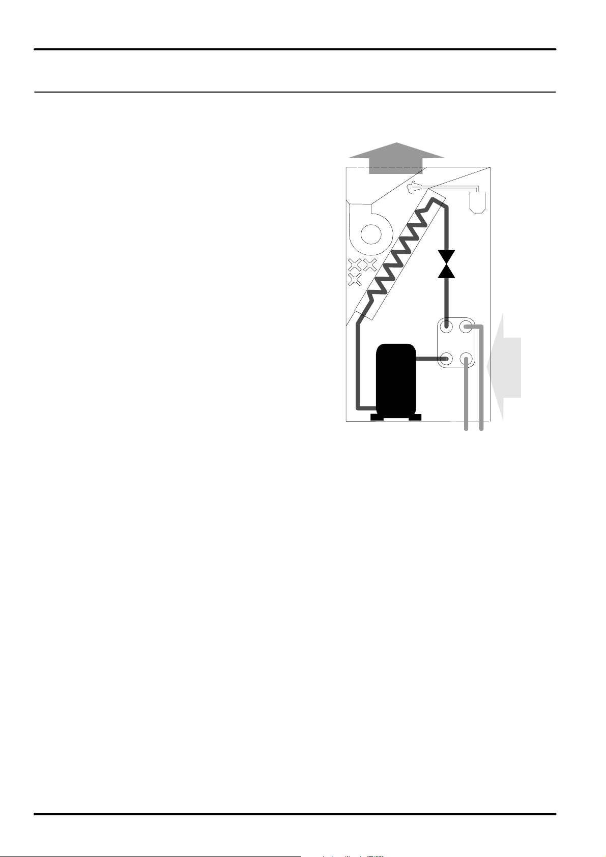
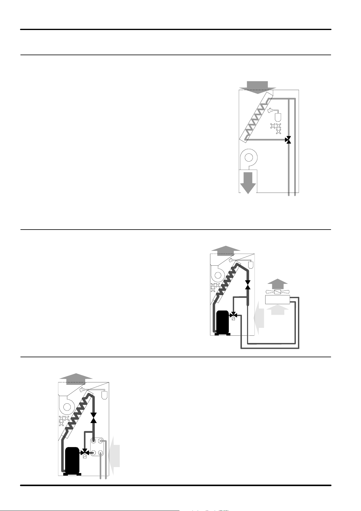
2.2 - Version W
Refrigerating circuit
The 4-6-8 models are provided with a
single refrigerating circuit, the units
5-7-9 have two refrigerating circuits. The
refrigerating circuit includes the compres
sor and the thermal expansion valve with an
external equalizer controlling the refriger
ant flow to the evaporator so as to keep a
steady overheating degree. Before the
thermal expansion valve there is a sight
glass enabling the visual check of the re
frigerant charge. A dryer filter is installed in
the liquid line for better cleaning and less
humidity in the circuit. On-off valves are
installed as standard to help the extraordi
nary maintenance of the circuits.
A suitably sized safety valve is installed af
ter the condenser; the valve is equipped
with flanged connections to allow the refrig
erant to be discharged outside through
suitable pipes. All low temperature parts of
the refrigerating circuit are insulated. The
refrigerating circuit is also provided with a
high pressure switch and a low pressure
switch. The low pressure switch has auto
matic resetting, whereas - for safety rea
sons due to possible high pressure in the
compressor - the high pressure switch
has manual resetting. The pressure switch
calibration values are shown in the installa
tion manual supplied with the machine.
Hiflex
Direct expansion water-condensed units
Condenser
The units are provided with a built-in stainless steel water condenser with braze-welded plates; this ad
vanced exchanger type gives the highest efficiency in heat exchange. In addition, a certain oversizing of
the exchanger has been provided so as to reduce pressure drops (and energy consumption of the water
pump) as much as possible and thus to allow the unit to operate with the external chiller in closed circuit,
even at high outdoor temperatures.
The units shall operate with throwaway water, tower water or water in closed circuit with external chill
er. In the operation with closed circuit, the water is cooled by the outdoor air in a heat exchanger; in this
case, to avoid unwished ice formation during winter, it is advisable to obtain the mixture always with a gly
col percentage (refer to the installation manual for the suitable percentages). The circulation of the waterglycol mixture is forced (the pump is not supplied). If throwaway water or tower water is used, when instal
ling the unit fit a mechanical filter on the water line to protect the condenser against possible impurities
contained in the water (for the condenser cleaning see the installation manual).
English
3All Versions
Hiflex
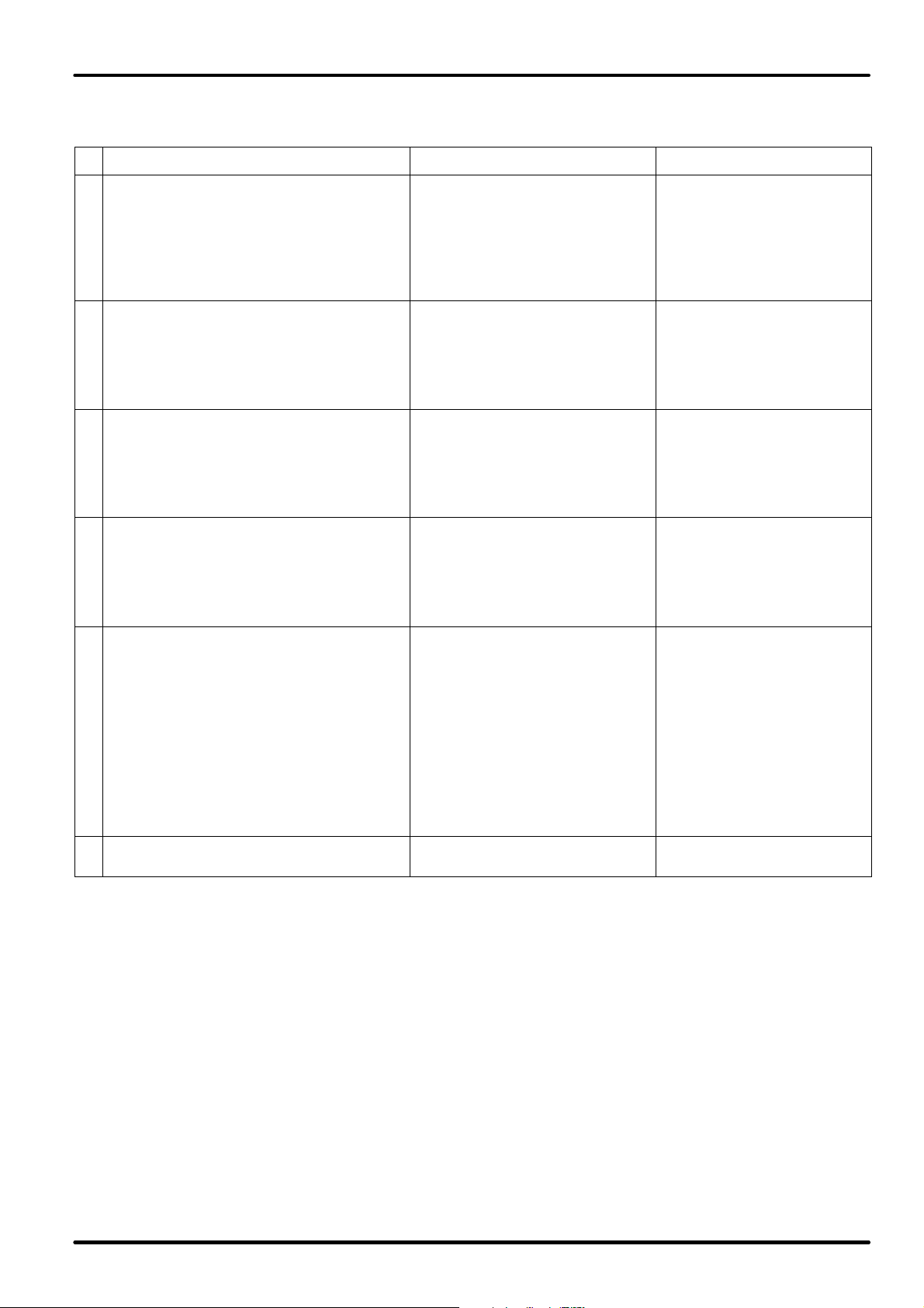
2.3 - Version D
Refrigerating circuit
The 8 models are provided with a single re
frigerating circuit, the units 9 have two re
frigerating circuits. The refrigerating circuit
includes the compressor and the thermal
expansion valve with an external equalizer
controlling the refrigerant flow to the evapo
rator so as to keep a steady overheating de
gree. Before the thermal expansion valve
there is a sight glass enabling the visual
check of the refrigerant charge. A dryer fil
ter is installed in the liquid line for better
cleaning and less humidity in the circuit.
The welded steel liquid receiver is avail
able in the refrigerating circuit to enable the
constant and even refrigerant flow to the ex
pansion valve. On-off valves are installed
as standard to help the extraordinary main
tenance of the circuits. For a safe opera
tion, during the start-up it is advisable to
install the non-return valve (supplied as
optional on request) on the connection of
the refrigerant with the external condenser
to protect the compressor from unexpected
refrigerant migrations (see installation dia
gramme).
A suitably sized safety valve is installed on the liquid receiver; the valve is equipped with flanged connec
tions to allow the refrigerant to be discharged outside through suitable pipes. All low temperature parts
of the refrigerating circuit are insulated. The refrigerating circuit is also provided with a high pressure
switch and a low pressure switch. The low pressure switch has automatic resetting, whereas - for safety
reasons due to possible high pressure in the compressor - the high pressure switch has manual reset
ting. The pressure switch calibration values are shown in the installation manual supplied with the ma
chine.
Air-condensed dualfluid units
External condensing unit
The units are coupled with the air condensers of Liebert HIROSS wide range in the versions with stan
dard axial fans and with low noise axial fans.For technical data and performances refer to the relevant tech
nical documentation.The following paragraphs describe the suggested couplings for the HIFLEX units as
a function of the outdoor air temperature. The data given follow are approximate and must always be veri
fied on the basis of the specific performances and working conditions required.
Hydraulic circuit
The unit is provided with a 3-way modulating valve, complete with incremental motor for the water flow
control to the coil; the opening or closing signals, generated by the electronic control, adjust the valve in
order to keep the ambient temperature at the required value. Through a series of menus it is possible to
set all parameters on the control for a correct adjustment, i.e. set-points, proportional bands, proportional
or proportional+integral adjustment, integrating factor and valve feature. It is possible to adjust the valve
manually in closing position (coil side) by means of a suitable wrench.
4 All Versions
English

2.4 - Version H
Refrigerating circuit
The 8 models are provided with a single refriger
ating circuit, the units 9 have two refrigerating cir
cuits. The refrigerating circuit includes the com
pressor and the thermal expansion valve with an
external equalizer controlling the refrigerant flow
to the evaporator so as to keep a steady overheat
ing degree. Before the thermal expansion valve
there is a sight glass enabling the visual check of
the refrigerant charge. A dryer filter is installed in
the liquid line for better cleaning and less humidity
in the circuit. On-off valves are installed as stan
dard to help the extraordinary maintenance of the
circuits. A suitably sized safety valve is installed
after the condenser; the valve is equipped with
flanged connections to allow the refrigerant to be
discharged outside through suitable pipes. All low
temperature parts of the refrigerating circuit are in
sulated. The refrigerating circuit is also provided
with a high pressure switch and a low pressure
switch. The low pressure switch has automatic re
setting, whereas - for safety reasons due to pos
sible high pressure in the compressor - the high
pressure switch has manual resetting. The pres
sure switch calibration values are shown in the
installation manual supplied with the machine.
Hiflex
Water-condensed dualfluid units
Condenser
The units are provided with a built-in stainless steel water condenser with braze-welded plates; this ad
vanced exchanger type gives the highest efficiency in heat exchange. In addition, a certain oversizing of
the exchanger has been provided so as to reduce pressure drops (and energy consumption of the water
pump) as much as possible and thus to allow the unit to operate with the external chiller in closed circuit,
even at high outdoor temperatures.
The units shall operate with throwaway water, tower water or water in closed circuit with external chiller.
In the operation with closed circuit, the water is cooled by the outdoor air in a heat exchanger; in this case,
to avoid unwished ice formation during winter, it is advisable to obtain the mixture always with a glycol
percentage (refer to the installation manual for the suitable percentages). The circulation of the water-gly
col mixture is forced (the pump is not supplied). If throwaway water or tower water is used, when installing
the unit fit a mechanical filter on the water line to protect the condenser against possible impurities con
tained in the water (for the condenser cleaning see the installation manual).
Hydraulic circuit
The unit is provided with a 3-way modulating valve, complete with incremental motor for the water flow
control to the coil; the opening or closing signals, generated by the electronic control, adjust the valve in
order to keep the ambient temperature at the required value. Through a series of menus it is possible to
set all parameters on the control for a correct adjustment, i.e. set-points, proportional bands, proportional
or proportional+integral adjustment, integrating factor and valve feature. It is possible to adjust the valve
manually in closing position (coil side) by means of a suitable wrench.
English
5All Versions
Hiflex
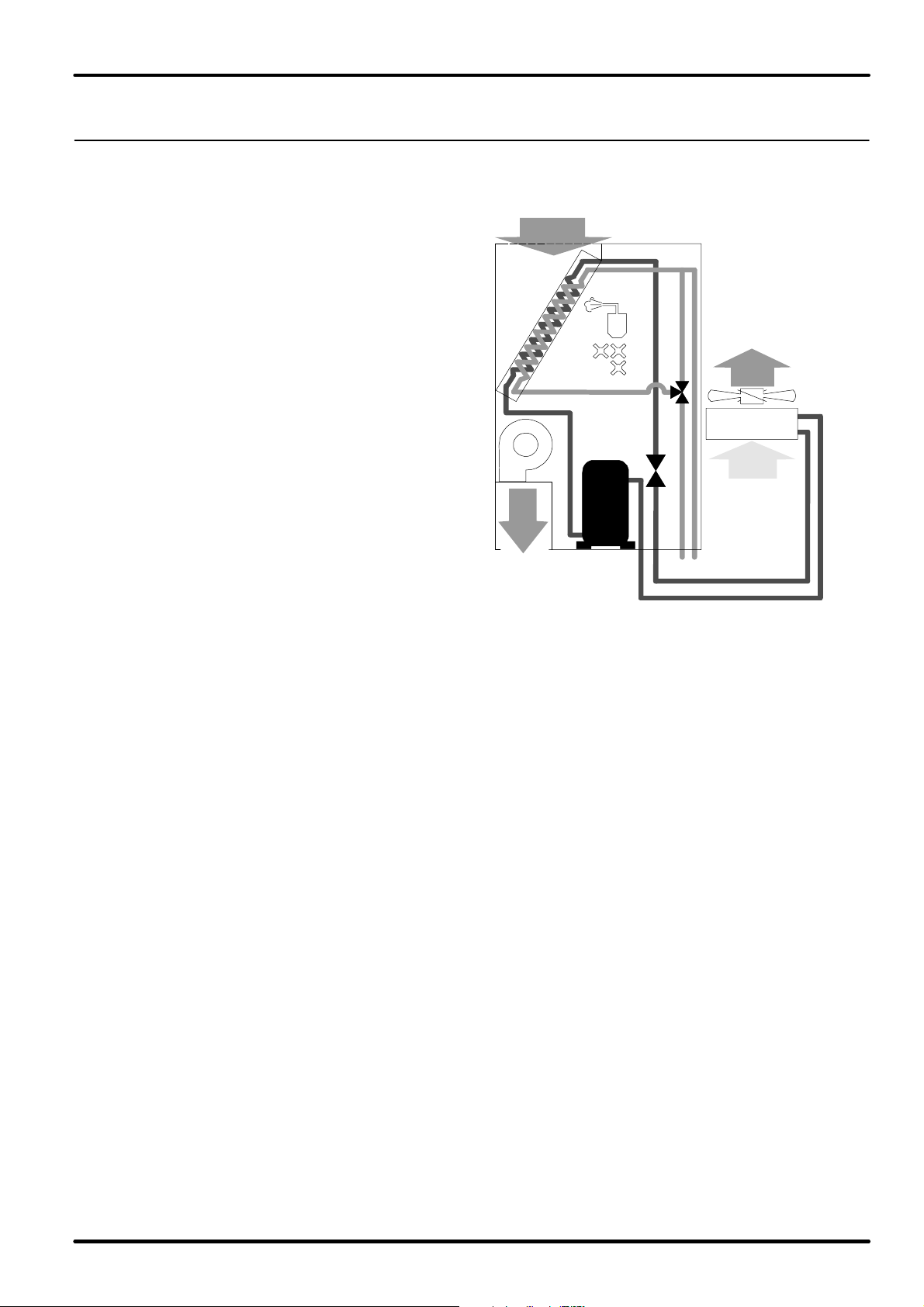
2.5 - Version F
Refrigerating circuit
The 8 models are provided with a single re
frigerating circuit, the units 9 have two re
frigerating circuits. The refrigerating circuit
includes the compressor and the thermal
expansion valve with an external equalizer
controlling the refrigerant flow to the evapo
rator so as to keep a steady overheating de
gree. Before the thermal expansion valve
there is a sight glass enabling the visual
check of the refrigerant charge. A dryer fil
ter is installed in the liquid line for better
cleaning and less humidity in the circuit.
On-off valves are installed as standard to
help the extraordinary maintenance of the
circuits. A suitably sized safety valve is
installed after the condenser; the valve is
equipped with flanged connections to allow
the refrigerant to be discharged outside
through suitable pipes. All low temperature
parts of the refrigerating circuit are insu
lated. The refrigerating circuit is also pro
vided with a high pressure switch and a low
pressure switch. Il pressostato di minima è
a riarmo automatico, mentre, per ragioni di sicurezza derivanti dalle possibili alte pressioni nel compres
sore, il pressostato di massima è dotato di riarmo manuale. I valori di taratura dei pressostati sono indicati
nel manuale di installazione, fornito a bordo macchina.
The low pressure switch has automatic resetting, whereas - for safety reasons due to possible high pres
sure in the compressor - the high pressure switch has manual resetting. The pressure switch calibration
values are shown in the installation manual supplied with the machine.
Freecooler units
Condenser
The units are provided with built-in stainless steel water condensers with braze-welded plates; this ad
vanced exchanger type gives the highest efficiency in heat exchange. In addition, a certain oversizing of
the exchanger has been provided so as to reduce pressure drops (and energy consumption of the water
pump) as much as possible and thus to allow the unit to operate with the external chiller in closed circuit,
even at high outdoor temperatures. The units shall operate with water in closed circuit with external chill
er. In the operation with closed circuit, the water is cooled by the outdoor air in a heat exchanger; in this
case, to avoid unwished ice formation during winter, it is advisable to obtain the mixture always with a gly
col percentage (refer to the installation manual for the suitable percentages). The circulation of the waterglycol mixture is forced (the pump is not supplied). To minimize water consumption and the condensing
pressure check during the different seasons of the year, the unit is provided with a water register supplied
as standard on the machine.
Hydraulic circuit
The unit is provided with a 2-way modulating valve, complete with incremental motor for the water flow
control to the freecooling coil; the opening or closing signals, generated by the electronic control, manage
the valve in order to keep the ambient temperature at the required value.
6 All Versions
English
2.6 - Version C
Hydraulic circuit
Each unit is provided with one hydraulic circuit.
The unit is provided with a 3-way modulating
valve, complete with incremental motor for the
water flow control to the coil; the opening or clos
ing signals, generated by the electronic control,
manage the valve in order to keep the ambient
temperature at the required value.
Through a series of menus it is possible to set all
parameters on the control for a correct adjust
ment, i.e. set-points, proportional bands, pro
portional or proportional+integral adjustment, in
tegrating factor and valve feature. It is possible to
adjust the valve manually in closing position (coil
side) by means of a suitable wrench.
Hiflex
Chilled water units
2.7 - Hiflex Constant versione A
Refrigerating circuit
Each unit is provided with a single refrigerat
ing circuit.. This is similar to the version's re
frigerant circuit (see para. 2.1), but a modulat
ing hot gas bypass valve is present. This valve
permits high precision evaporating tempera
ture regulation.
For other carachteristics, see para. 2.1.
2.8 - Hiflex Constant versione W
Direct expansion water-condensed unit with high precision control
Direct expansion air-condensed unitswith high precision control
Refrigerating circuit
Each unit is provided with a single refrigerating circuit..This is
similar to the version's refrigerant circuit (see para. 2.2), but a
modulating hot gas bypass valve is present. This valve permits
high precision evaporating temperature regulation.
For other carachteristics, see para. 2.2.
Here is a summary list of the peculiar features of the different ver
sions:
English
7All Versions
Hiflex
Here is a summary list of the peculiar features of the different versions:
Heat exchange Refrigerating circuit Installation
The unit cools the air by an air/refrigerant
coil (direct expansion).
A
The refrigerating circuit condenser is ex
ternally mounted, air-cooled.
The unit cools the air by an air/refrigerant
coil (direct expansion).
W
The refrigerating circuit plate condenser is
indoor, cooled by a water flow.
The dualfluid unit cools the air flow by
means of an air/refrigerant coil (direct ex
pansion) or, as an alternative, an air/water
D
coil.
The refrigerating circuit condenser is ex
ternally mounted, air-cooled.
The dualfluid unit cools the air flow by
means of an air/refrigerant coil (direct ex
pansion) or, as an alternative, an air/water
H
coil.
The refrigerating circuit plate condenser is
indoor, cooled by a water flow.
The freecooler unit cools the air flow by
means of an air/refrigerant coil (direct ex
pansion) or, as an alternative, an air/water
coil. The water flow is cooled by an exter
nal rad-cooler. When the external tempe
rature is higher than the ZET, the water
F
exchanges heat with the refrigerant in the
internal water/refrigerant plate condenser.
When the external temperature is lower
than the ZET, the water is cooled as much
as sufficiently to cool the air directly in the
air/water coil.
The unit cools the air flow by an air/water
C
coil.
The refrigerating circuits are not
pre-charged with refrigerant.
There is a liquid receiver on
which the safety valve is instal
led.
The Constant units are equiped
with hot gas by-pass valve.
The refrigerating circuits are
pre-charged with refrigerant.
The safety valve is installed
downstream the condenser.
The Constant units are equiped
with hot gas by-pass valve.
The refrigerating circuits are not
pre-charged with refrigerant.
There is a liquid receiver on
which the safety valve is instal
led.
The refrigerating circuits are
pre-charged with refrigerant.
The safety valve is installed
downstream the condenser.
The refrigerating circuits are
pre-charged with refrigerant.
The safety valve is installed
downstream the condenser.
The unit has no refrigerating cir
cuit.
The unit must be connected
to the external condenser
and the refrigerant must be
charged.
The unit must be connected
to the piping of the cooling
water of the water/refrigerant
condenser.
It is necessary to connect
the unit to the external con
denser, to charge it with re
frigerant and to connect the
chilled water piping for the
air/water coil.
The unit must be connected
to the chilled water piping
for the air/water coil and to
the cooling water piping of
the water/refrigerant con
denser.
The unit must be connected
to the closed water circuit
with the rad-cooler.
The unit must be connected
to the chilled water piping.
8 All Versions
English

2.9 - Air control
All units are available in the three configurations shown below. The Hiflex Constant units are supply with
upward air flow (Over) only.
UNDER
2.10 - Dimensions and accessibility
Hiflex
OVER
The unit structures are made in three sizes with the following dimensions:
W D H
Size 4: 750 450 1950
Size 6: 750 600 1950
Size 8: 750 750 1950
Size 5: 1490 450 1950
Size 7: 1490 600 1950
Size 9: 1490 750 1950
Ordinary and special maintenance is easier thanks to the front access enabling the replacement of the
air filters, the intervention on the components of the refrigerating circuit - such as compressor, liquid re
ceiver, thermal expansion valve, refrigerant sight glass, drying filter - or on the fan, the humidifier, the elec
tric board, the electronic control, the electric heating elements.
The refrigerant, electric and hydraulic connections are placed on the lower part of the unit.
English
9All Versions

Hiflex
3 - Operating limits
All versions
HIFLEX units are provided for operating within the following working ranges (the limits concern new units
on which correct installation and maintenance have already been made):
Ambient conditions:
from 18.0C, 45% R.H. to 27.0C, 55% R.H.
To avoid the formation of too much condensate which might cause water drops entrainment, it is important
to check that the latent capacity - difference between total and sensible load at the selected conditions
doesn't exceed the value of 5.5 kW.
Air flow
The minimum and maximum values are shown in the tables of the useful available heads. However, safety
devices are provided as standard to protect the various components from any damages due to operation
outside the indicated limits.
Power tolerances
Standard voltage (V): 10%
Standard frequency (Hz): 2
Versions A and D
Outdoor conditions:
low limit = +10C (from +9C to -20C with Variex accessory installed on the condenser)
high limit determined by the size of the coupled condenser. Exceeding these limits causes the compressor
lock due to the safety pressure switch, which can be restored only by hand.
Condensing unit installation:
Maximum distance between ambient unit and external air condenser: 30 m (equivalent lentgh).
Max. geodetic height difference between condenser and unit: 3 m (if the condenser is placed underneath
the ambient unit).
Attenzione:
I ventilatori centrifughi dispongono di prevalenza pari a quella nominale di progetto. Se le perdite di
carico del condotto di espulsione sono esigue (condotto molto corto o sovradimensionato) la corren
te assorbita dal motore può superare il valore di targa del motore. In questi casi è assolutamente
necessario attenersi ad una delle seguenti istruzioni:
1) Introdurre nel circuito delle perdite di carico supplementari (inserendo nel condotto una serranda
manuale o una tagliola).
2) Ridurre il numero di giri del ventilatore ovunque sia possibile, ossia quando il ventilatore è
accoppiato mediante cinghie al motore oppure quando è dotato di motore monofase a più
velocità.
N.B.: L'operazione può considerarsi definitiva quando l'assorbimento del ventilatore sarà
prudenzialmente inferiore al valore di targa di almeno il 10%.
10 All Versions
English

4 - Component features
4.1 - Fan
Double section, galvanized steel, centrifugal fan, forward blades.
High efficiency.
The motor is single-phase; provided with internal thermal protec
tion.
The fan wheel is statically and dynamically balanced; the bearings
are self-lubricating.
4.2 - Compressor
SCROLL compressors
High COP (Coefficient Of Performance)
High MTBF (Minimum Time Between Failures)
Low sound level.
Vibration-damped.
Provided with internal thermal protection.
Low pickup current (equalization of the internal pressures).
Hiflex
4.3 - Coils
High front surface.
Made of copper pipes and aluminium fins.
Fins treated with hydrofile styrol acrylic paints to with
stand corrosive atmospheres.
Low pressure drop.
High SHR (Sensible Heat Ratio).
4.4 - Frame and panels
The sheet steel structure, painted with RAL 7035 epoxypolyester powders, is assembled by stainless steel screws;
the paneling system ensures higher stiffness; there will also
be some pluggings (compressor space and fan) for guaran
teeing both safety and high acoustic absorption.
The electric board protecting panel is assembled on hinges
to make the access easier; this can be opened by the fast
closing lock. The side panels are screwed to the supports.
The rear panel is screwed directly to the frame.
The air returns from the machine top in machines with un
derfloor air delivery, whereas in machines with upward air delivery it returns through the metal grid on the
front panel.
The compressor is housed in a closed space in the lower part of the unit and is completely insulated
against the air flow. The compressor section can be reached even during the unit operation by removing
the front panel and the protection plugging.
The panels are lined with thermoacoustic insulating material - class 1.
English
11All Versions
Hiflex
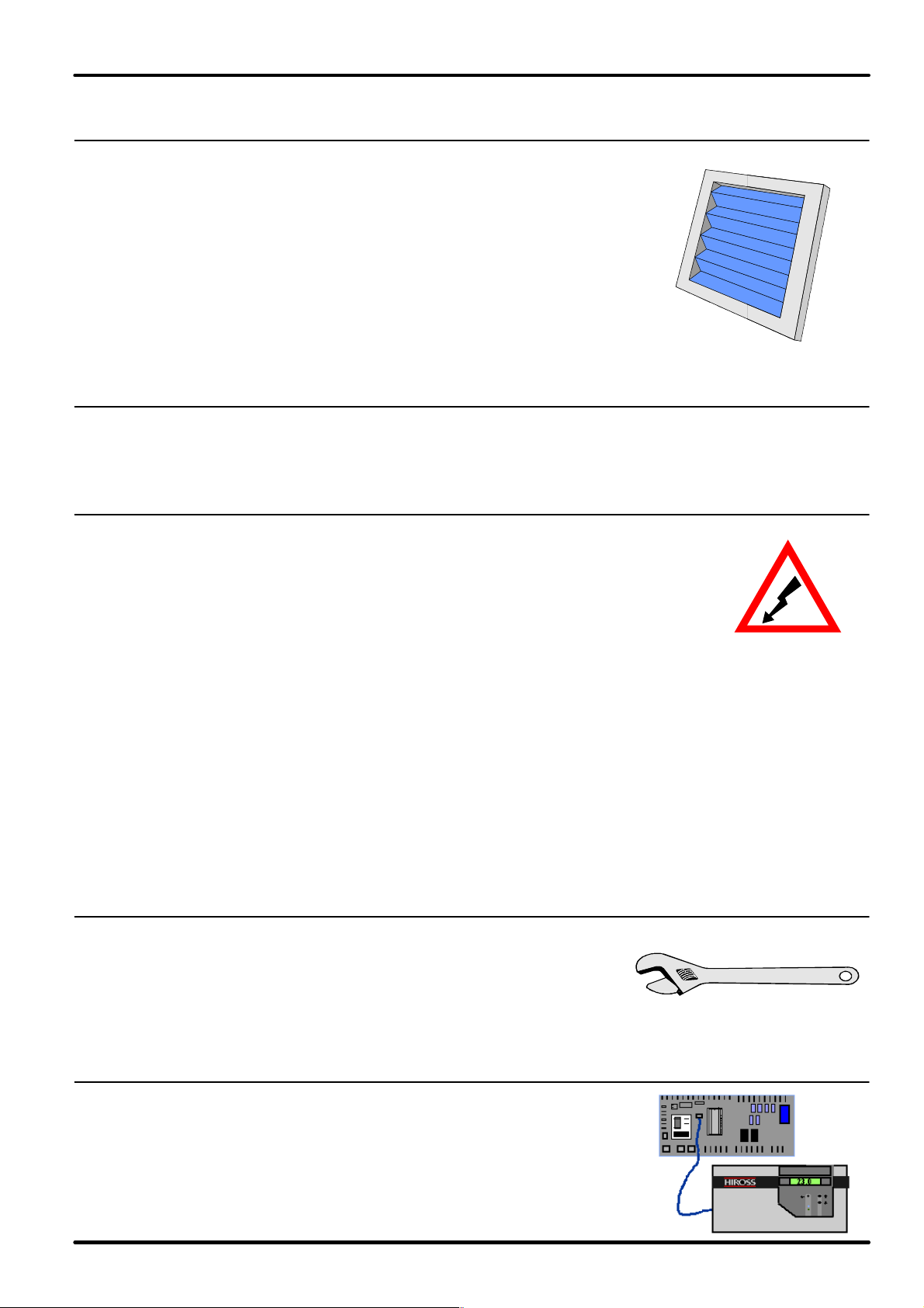
4.5 - Filters
Removable filters.
The guaranteed efficiency degree is from G3 and F9 (CEN EN 779,
corresponding to EU3 and EU9 according to Eurovent EU4/5).
The folded structure of the filters gives high filtration efficiency and
low pressure drop.
The filter media used consists of synthetic fibre cells. The frame is
made of cardboard.
Pre-filtration system for Over models.
4.6 - Refrigerants
The units are designed for being used with refrigerant R22 or, as optional, R407C.
4.7 - Electric board
The electric board is housed in the front part in a space insulated against
the air flow and protected by a plastic crankcase, so as to avoid tamper
ing by non-authorized personnel and to protect the electric board parts
supplied with a voltage higher than 24 V.
The electric board complies with the norm 204-1 IEC.
The air conditioners have been provided for operating at 400 V/3/50
Hz+N+G (as special alternative execution, the version with 220V/3/50Hz
+ G can be supplied) and at 380 V/3/60 Hz+N+G and 230 /3/60 Hz+G.
Magnetothermal switches are supplied as protection of every electric component.
A single-phase transformer has been provided for supplying power to the secondary circuit at 24 V.
A main switch with door-locking handle is installed in series on the safety crankcase to prevent it from
being removed when the switch is in the operating position.
There will be an automatic start-up after a possible stop due to power supply lack.
Additional terminals for remote start-up and carry of some operating conditions (fans and compressors)
or connection of additional devices (Liquistat, Firestat, Smokestat, clogged filters) are set in series on the
terminal board of the electric board. On the terminal board there is also a clean contact for the remote
signalling of the general alarm.
4.8 - Accessibility
Having access to the compressor is possible even when the unit
is operating by removing the front panel. The access to the fan is
executed with the greatest care for easier interventions (mainte
nance and/or fan replacement).
4.9 - Control system
Very simple user interface.
Immediately intelligible utilization of the control unit system with
LCD.
Net connectivity of several units.
Possible utilization of the Hiromatic graphic terminal.
12 All Versions
English

4.10 -Packing
The air conditioners are usually packed in wooden pallets and carton
boxes. An air bubble plastic film protects the painted surfaces.
On request,
wooden crates or cases can be supplied for the sea transport.
4.11 -Product quality and safety
The product conforms to European Union directives
98/37/CE (89/392/CEE; 91/368/CEE; 93/68/CEE),
89/336/CEE; 73/23/CEE; 97/23/EC.
Further, the Company Quality System of Air Condi
tioning Division is approved by LRQA according to
the standards UNI EN ISO 9001: 2000 and the prod
uct is the result of activities performed in compliance with the provisions contained in the Quality proce
dures and plans.
The unit is supplied complete with a test certificate and conformity declaration and
control component list.
The units of the Hiflex series are marked as they comply with the European directives con
cerning mechanical, electrical, electromagnetic and pressure equipment safety.
Hiflex
English
13All Versions

Hiflex
5 - Condensing section
5.1 - Air condensers
The units may be connected to a wide range of our condensers
single circuit (HCA) or double circuit (HBA).
The following paragraphs describe the suggested coupling for
Hiflex units as a function of the outdoor air temperature. The data
given below are approximate and must always be verified on the
basis of the specific performances and different operating condi
tions.
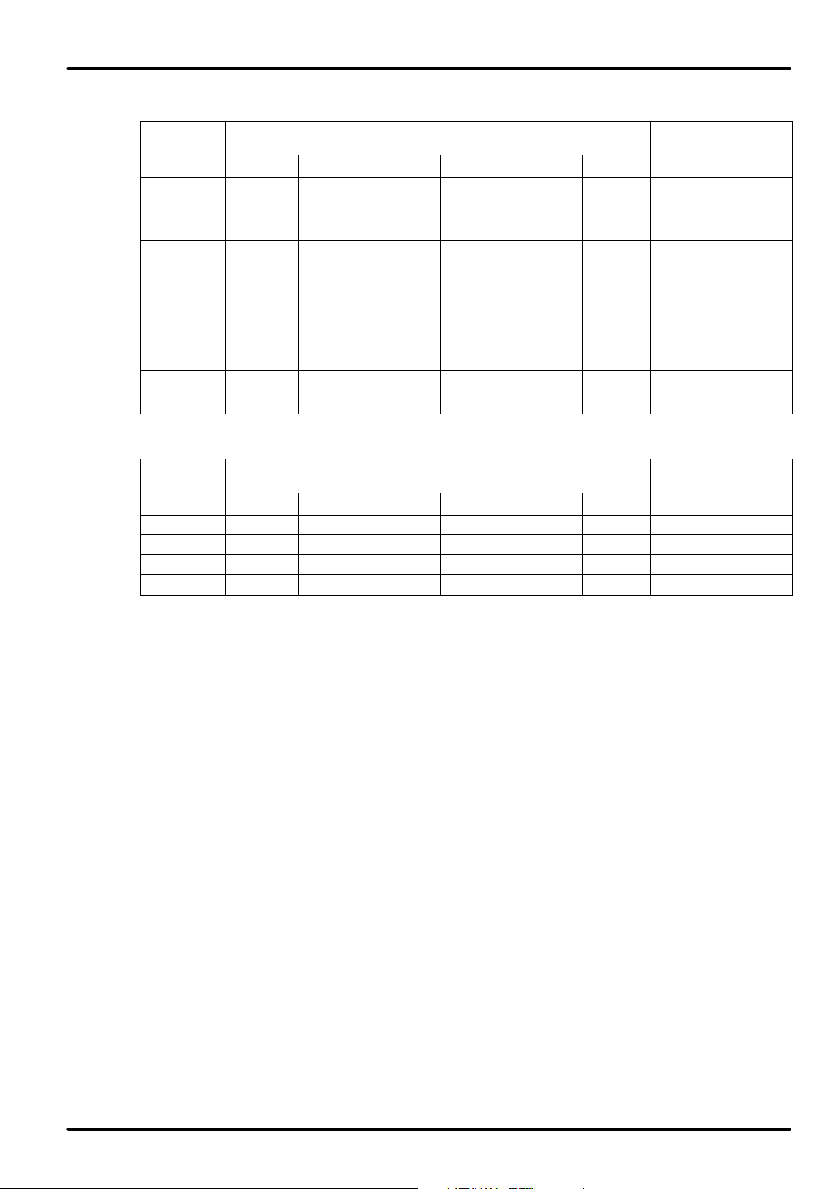
Performances Electric data Overall dimensions
Standard
Model
HCA07 7.1 1900 44 230/1/50(a) 1 0.18 803 451 703
HCA10 9.4 4100 47 230/1/50(a) 2 0.36 1253 451 703
HCA14 14.5 4430 44 230/1/50(a) 1 0.29 1175 797 890
HCA17 16.5 4160 44 230/1/50(a) 1 0.29 1175 797 890
HCA24 24.0 7950 51 230/1/50(b) 1 0.52 1325 1098 992
HCA29 28.3 7530 51 230/1/50(b) 1 0.52 1325 1098 992
HCA33 32.1 8320 47 230/1/50(a) 2 0.58 2125 797 890
HBA33 32.1 8320 47 230/1/50(a) 2 0.58 2125 797 890
HCA42 41.6 15900 54 230/1/50(b) 2 1.04 2425 1098 992
HCA49 47.9 15900 54 230/1/50(b) 2 1.04 2425 1098 992
HBA49 47.9 15900 54 230/1/50(b) 2 1.04 2425 1098 992
HCA58 56.6 15060 54 230/1/50(b) 2 1.04 2425 1098 992
HCA74 72 23850 57 230/1/50(b) 3 1.56 3526 1098 992
HBA74 72 23850 57 230/1/50(b) 3 1.56 3526 1098 992
HCA87 84.9 22590 57 230/1/50(b) 3 1.56 3526 1098 992
HBA87 84.9 22590 57 230/1/50(b) 3 1.56 3526 1098 992
HCA95 91.5 21750 57 230/1/50(b) 3 1.56 3526 1098 992
HBA99 113 30120 58 230/1/50(b) 4 2.08 4625 1098 992
Duty (d) Air flow
kW m3/h dB(A) V/ph/Hz nº kW mm mm mm
SPL 5 m
Supply
Number
of fans
Total
absorbed power
Width Depth
Height
c
(
)
14 All Versions
English

Performances Electric data Overall dimensions
Model
Low noise
Model
Duty (d) Air flow
SPL 5 m
Supply
Number of
fans
Total
absorbed
power
Width Depth
kW m3/h db(A) V/ph/Hz nº kW mm mm mm
HCA07 5.0 1230 38 230/1/50(a) 1 0.16 803 451 703
HCA10 7.2 2750 41 230/1/50(a) 2 0.32 1253 451 703
HCA14 11.1 3230 40 230/1/50(a) 1 0.20 1175 797 890
HCA17 12.7 2920 40 230/1/50(a) 1 0.20 1175 797 890
HCA24 20.4 6260 45 230/1/50(b) 1 0.37 1325 1098 992
HCA29 23.6 5950 45 230/1/50(b) 1 0.37 1325 1098 992
HCA33 25 5840 43 230/1/50(a) 2 0.39 2125 797 890
HBA33 25 5840 43 230/1/50(a) 2 0.39 2125 797 890
HCA42 36.4 12520 48 230/1/50(b) 2 0.74 2425 1098 992
HCA49 40.8 12520 48 230/1/50(b) 2 0.74 2425 1098 992
HBA49 40.8 12520 48 230/1/50(b) 2 0.74 2425 1098 992
HCA58 47.2 11900 48 230/1/50(b) 2 0.74 2425 1098 992
HCA74 61.2 18780 51 230/1/50(b) 3 1.11 3526 1098 992
HBA74 61.2 18780 51 230/1/50(b) 3 1.11 3526 1098 992
HCA87 70.8 17850 51 230/1/50(b) 3 1.11 3526 1098 992
HBA87 70.8 17850 51 230/1/50(b) 3 1.11 3526 1098 992
HCA95 73.5 16710 51 230/1/50(b) 3 1.11 3526 1098 992
HBA99 95 25380 51 230/1/50(b) 4 1.63 4625 1098 992
(a): available with 230V/1ph/60Hz.
(b): available with 400V/3ph/60Hz
(c): vertical flow installation.
(d): at the following conditions: dT (condensing temp - outdoor temp) = 15°C; outdoor temperature 35°C; 0 m a.s.l.
Hiflex
Height
c
(
)
Coupling of remote air condensers
Coupling of Condensers for HIFLEX single circuit
External temperature
Model
up to 30oC
Standard Low noise Standard Low noise Standard Low noise Standard Low noise
4M U/O A HCA 07 HCA 07 HCA 07 HCA 07 HCA 07 HCA 10 HCA 14 HCA 14
4S/P U/O A HCA 07 HCA 07 HCA 07 HCA 07 HCA 07 HCA 10 HCA 14 HCA 14
4L/G U/O A HCA 07 HCA 10 HCA 10 HCA 10 HCA 10 HCA 14 HCA 14 HCA 14
6S/P U/O A HCA 10 HCA 10 HCA 10 HCA 14 HCA 14 HCA 14 HCA 14 HCA 14
6L/G U/O A HCA 10 HCA 14 HCA 14 HCA 14 HCA 14 HCA 24 HCA 24 HCA 24
8S/P U/O A HCA 14 HCA 14 HCA 14 HCA 17 HCA 17 HCA 24 HCA 24 HCA 29
8L/G U/O A/D HCA 14 HCA 14 HCA 14 HCA 24 HCA 24 HCA 24 HCA 29 HCA 42
External temperature
up to 35oC
External temperature
up to 40oC
External temperature
up to 46oC
English
15All Versions
Hiflex
Model
Model
Coupling of Condensers for HIFLEX double circuit
External temperature
Model
5S/P U/O A 2 x HCA07 2 x HCA07 2 x HCA07 2 x HCA07 2 x HCA07 2 x HCA10 2 x HCA14 2 x HCA14
5L/G U/O A 2 x HCA07 2 x HCA10 2 x HCA10 2 x HCA10 2 x HCA10 2 x HCA14 2 x HCA14
7S/P U/O A 2 x HCA10 2 x HCA10 2 x HCA10 2 x HCA14 2 x HCA14
7L/G U/O A 2 x HCA10 2 x HCA14 2 x HCA14 2 x HCA14 2 x HCA14
9S/P U/O A 2 x HCA14 2 x HCA14 2 x HCA14
9L/G U/O A/D 2 x HCA14 2 x HCA14 2 x HCA14
up to 30oC
Standard Low noise Standard Low noise Standard Low noise Standard Low noise
External temperature
up to 35oC
2 x HCA17
or
1 x HBA33
2 x HCA24
or
1 x HBA49
External temperature
up to 40oC
2 x HCA17
or
1 x HBA33
2 x HCA24
or
1 x HBA49
2 x HCA17
or
1 x HBA33
2 x HCA24
or
1 x HBA49
2 x HCA24
or
1 x HBA49
2 x HCA24
or
1 x HBA49
External temperature
up to 46oC
2 x HCA24
or
1 x HBA49
2 x HCA24
or
1 x HBA49
2 x HCA24
or
1 x HBA49
2 x HCA24
or
1 x HBA49
2 x HCA29
2 x HCA24
or
1 x HBA49
2 x HCA24
or
1 x HBA49
2 x HCA29
2 x HCA42
or
1 x HBA87
Coupling of Condensers for HIFLEX constant
External temperature
Model
4S/P CA HCA 07 HCA 07 HCA 07 HCA 07 HCA 07 HCA 10 HCA 10 HCA 14
4L/G CA HCA 07 HCA 07 HCA 07 HCA 10 HCA 10 HCA 14 HCA 14 HCA 24
6S/P CA HCA 10 HCA 10 HCA 10 HCA 14 HCA 14 HCA 14 HCA 24 HCA 24
8S/P CA HCA 14 HCA 14 HCA 14 HCA 14 HCA 14 HCA 24 HCA 24 HCA 29
The coupling applies for a total equivalent distance of max. 30 m and in compliance with the instructions for the unit installation.
Max. geodetic height difference between condenser and unit: 3 m (if the condenser is placed underneath the ambient unit).
up to 30oC
Standard Low noise Standard Low noise Standard Low noise Standard Low noise
External temperature
up to 35oC
External temperature
up to 40oC
External temperature
up to 46oC
16 All Versions
English

5.2 - Water condensers.
The water-condensed units are provided with a water/refrigerant
exchanger with braze-welded plates made of stainless steel;
this advanced exchanger type gives the highest efficiency in heat
exchange. In addition, a certain oversizing of the exchanger has
been provided so as to reduce pressure drops (and energy con
sumption of the water pump) as much as possible and thus to
allow the unit to operate with the external chiller in closed circuit,
even at high outdoor temperatures.
The O/UW units are designed for operating with mains water,
tower water or water in closed circuit with an external chiller. When
operating in a closed circuit, the water is cooled by the outdoor air
in a heat exchanger; in this case, to avoid unwanted ice formation
during winter, it is advisable to use a water/glycol mixture. The cir
culation of the water-glycol mixture is forced (the pump is not
supplied). If mains water or tower water is used, when installing
the unit fit a mechanical filter on the water line to protect the con
denser against possible impurities contained in the water (for condenser cleaning see the installation man
ual).
Hiflex
5.3 - Dry coolers
Our dry-coolers are built with a copper/aluminium cooling coil and axial fan(s).
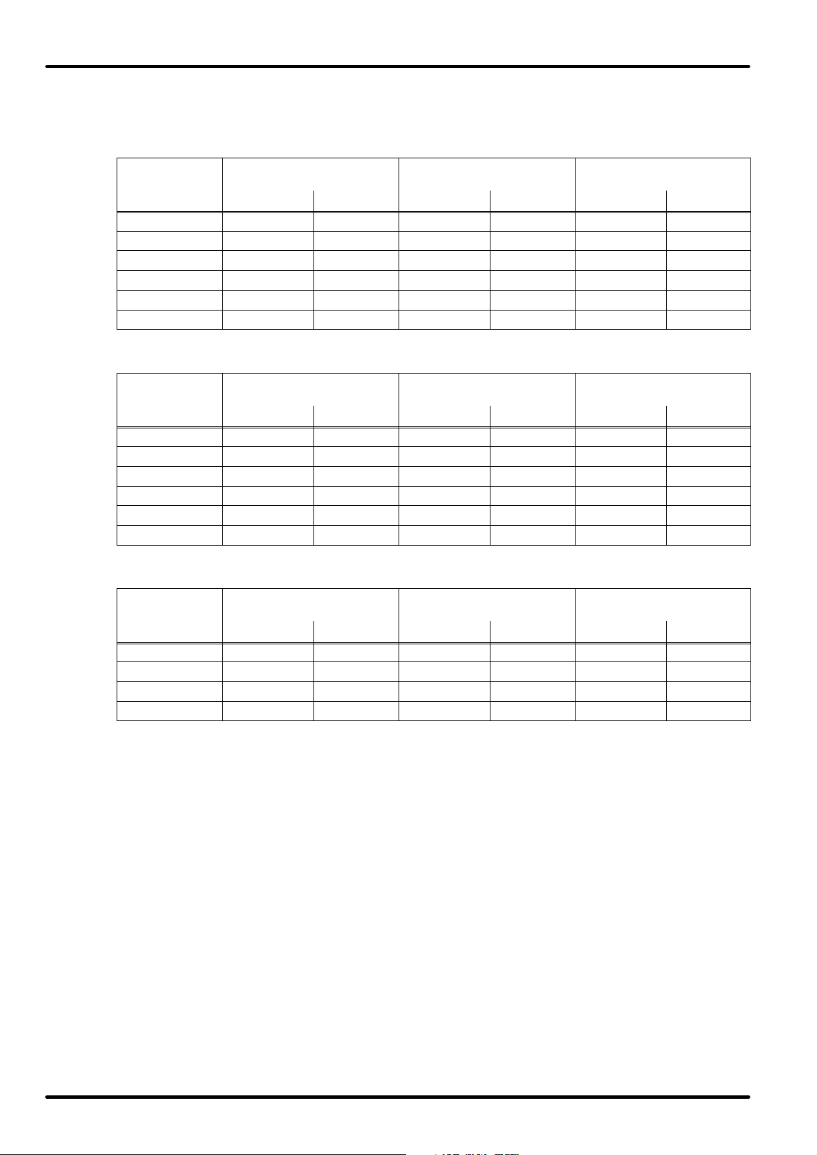
The main data on dry coolers is shown in the following table:
Standard
Model
DSM009 9 6.600 50 230/1/50 1 0.64 1.250 900 990
DSM013 13.5 5.100 50 230/1/50 1 0.64 1.250 900 990
DSM018 17.6 13.200 53 230/1/50 2 1.28 2.050 900 990
DSM022 22.4 12.600 53 230/1/50 2 1.28 2.050 900 990
DSM028 27.5 18.900 54 230/1/50 3 1.92 2.850 1.260 990
DST030 33 20.500 55 400/3/50 2 1.44 2.750 1.260 1.140
DST040 39 20.000 55 400/3/50 2 1.44 2.730 1.260 1.140
DST050 50 30.750 57 400/3/50 3 2.16 3.900 1.260 1.140
DST060 58 30.000 57 400/3/50 3 2.16 3.900 1.260 1.140
DST070 68 28.350 57 400/3/50 3 2.16 3.900 1.260 1.140
DST080 80 40.000 58 400/3/50 4 2.88 5.060 1.260 1.140
DST110 108 52.500 59 400/3/50 3 4.35 5.010 1.640 1.500
DST135 134 70.000 60 400/3/50 4 5.8 6.520 1.640 1.500
DST175 175 110.000 64 400/3/50 4 12.8 6.520 1.640 1.570
DST220 220 106.000 64 400/3/50 4 12.8 6.520 1.640 1.570
DST270 270 132.500 65 400/3/50 5 16 8.055 1.640 1.570
DST290 284 204.000 67 400/3/50 8 25.6 6.155 2.420 1.570
DST330 326 208.000 63 400/3/50 8 17.6 7.355 2.440 1.770
DST360 362 255.000 68 400/3/50 10 32 7.555 2.420 1.770
DST400 400 190.000 63 400/3/50 8 17.6 7.355 2.440 1.770
DST450 447 235.000 68 400/3/50 10 2 7.555 2.420 1.570
DST500 500 237.500 64 400/3/50 10 32 9.055 2.440 1.770
Duty (a) Air flow
kW m3/h db(A) V/ph/Hz nº kW mm mm mm
Performances Electric data Overall dimensions
SPL
10 m
Supply
Number of
fans
Total
absorbed
power
Width Depth
Height
(b)
English
17All Versions

Hiflex
Performances Electric data Overall dimensions
Low Noise
Model
Duty(
a
) Air flow
SPL
10 m (c)
Supply
Number of
fans
Total
absorbed
power
Width Depth Height (
kW m3/h db(A) V/ph/Hz nº kW mm mm mm
DLM008 7.5 4.700 39 230/1/50 1 0.29 1250 900 990
DLM011 10.5 3.700 39 230/1/50 1 0.29 1250 900 990
DLM015 15.5 9.500 42 230/1/50 2 0.58 2.050 900 990
DLM018 18 9.000 42 230/1/50 2 0.58 2.050 900 990
DLM023 23 14.000 43 230/1/50 3 0.87 2.850 1260 990
DLT027 27.5 15.000 47 400/3/50 2 0.7 2.750 1260 1.140
DLT030 30 14.500 47 400/3/50 2 0.7 2.730 1260 1.140
DLT040 40 22.500 49 400/3/50 3 1.05 3.900 1260 1.140
DLT047 47 21.750 49 400/3/50 3 1.05 3.900 1260 1.140
DLT055 54 20.250 49 400/3/50 3 1.05 3.900 1260 1.140
DLT065 65 29.000 50 400/3/50 4 1.4 5.060 1260 1.140
DLT085 84 40.500 54 400/3/50 3 2.16 5.010 1.640 1.500
DLT110 112 54.000 55 400/3/50 4 2.88 6.520 1.640 1.500
DLT130 130 67.000 51 400/3/50 4 3.72 6.520 1.640 1.570
DLT160 157 62.000 51 400/3/50 4 3.72 6.520 1.640 1.570
DLT190 190 77.500 52 400/3/50 5 4.65 8.055 1.640 1.570
DLT210 212 123.000 54 400/3/50 8 7.44 6.155 2.420 1.570
DLT250 253 132.000 51 400/3/50 8 6.88 7.355 2.440 1.770
DLT270 270 153.750 55 400/3/50 10 9.3 7.555 2.420 1.770
DLT290 290 118.000 51 400/3/50 8 6.88 7.355 2.440 1.770
DLT310 310 137.500 55 400/3/50 10 9.3 7.555 2.420 1.570
DLT350 350 147.500 52 400/3/50 10 8.6 9.055 2.440 1.770
(a): at the following conditions: outdoor temperature = 35°C, inlet/outlet water temperature = 45°C/40°C.
(b): vertical flow installation.
(c): according to DIN45635.
b
)
18 All Versions
English
Coupling of Dry-coolers
Model
Model
Model
Coupling of Dry Coolers for HIFLEX single circuit
External temperature
Model
4S/P U/O W DSM009 DLM008 DSM009 DLM008 DSM013 DLM011
4L/G U/O W DSM009 DLM008 DSM009 DLM008 DSM013 DLM011
6S/P U/O W DSM009 DLM008 DSM009 DLM008 DSM018 DLM015
6L/G U/O W DSM009 DLM011 DSM013 DLM011 DSM018 DLM015
8S/P U/O W DSM013 DLM011 DSM013 DLM011 DSM018 DLM015
8L/G U/O W/F/H DSM013 DLM011 DSM013 DLM015 DSM022 DLM018
up to 30oC
Standard Low noise Standard Low noise Standard Low noise
Coupling of Dry Coolers for HIFLEX double circuit
External temperature
Model
5S/P U/O W DSM009 DLM008 DSM013 DLM011 DSM018 DLM015
5L/G U/O W DSM013 DLM011 DSM013 DLM015 DSM028 DLM018
7S/P U/O W DSM013 DLM015 DSM018 DLM015 DSM028 DLM018
7L/G U/O W DSM018 DLM015 DSM018 DLM015 DST030 DLM023
9S/P U/O W DSM018 DLM015 DSM022 DLM018 DST040 DLT027
9L/G U/O W/F/H DSM022 DLM018 DSM028 DLM023 DST050 DLT040
up to 30oC
Standard Low noise Standard Low noise Standard Low noise
External temperature
up to 35oC
External temperature
up to 35oC
External temperature
up to 40oC
External temperature
up to 40oC
Hiflex
Coupling of Dry Coolers for HIFLEX constant
External temperature
Model
4S/P CW DSM009 DLM008 DSM009 DLM008 DSM013 DLM011
4L/G CW DSM009 DLM008 DSM009 DLM008 DSM013 DLM011
6S/P CW DSM009 DLM008 DSM009 DLM008 DSM018 DLM015
8S/P CW DSM013 DLM011 DSM013 DLM011 DSM018 DLM015
up to 30oC
Standard Low noise Standard Low noise Standard Low noise
External temperature
up to 35oC
External temperature
up to 40oC
English
19All Versions

Hiflex
6 - Technical remarks
6.1 - Fluid, R407C
Recent international agreements (Montreal, London,
Copenhagen, Vienna and San Josè) have abolished
- with precise expiry dates - the production of the
HCFC fluids (e.g.: R22) considered as harmful for the
ozone layer. The new HFC fluids (hydrofluorocar
bons) which have to replace them contain no chlo
rine, a dangerous substance for the ozone layer. The
refrigerant R407C replace the fluid R22.
Its main features are:
Non-azeotropic mixture made of
R32/R125/R134a in which the percentage weight composition is, in ratio, 23/25/52.
Thermophysical features similar to R22.
ODP (Ozone Depletion Potential) equal to 0.
Not flammable in the air.
Low toxicity degree.
The new HFC fluids are essentially incompatible with the mineral oils which are usually used with the fluids
R12 and R22.
Therefore, new synthetic lubricants based on polyester molecules have been developed for their use.
Note: considering the peculiar thermophysical features of the fluid we give the description of the refrigera
ting cycle shown in the phase diagram of the R407C.
Attention
The differences between the units
operating with the fluid R407C and
those operating with the fluid R22 are
described below.
P (bar)
PC
PE
High pressure side Low pressure side
TCB: condensation temperature
bubble point (Liquid)
TCR: condensation temperature
dew point (Vapor)
TCM: average condensation temperature
(TCB+TCM)/2
TL: temperature of the refrigerant at
the expansion valve inlet
Overheating = TAC - TER
Isoterms
h (kJ/kg)
TLV: liquid-steam temperature
TER: evaporation temperature
dew point (Vapor)
TEM: average evaporation temperature
(TLV+TER)/2
TAC: temperature of the refrigerant at
the compressor inlet
Sub-cooling = TCB -TL
20 All Versions
English

40%
35%
30%
25%
20%
15%
Hiflex
10%
Percentage of ethylene glycol mixed with water
5%
0%
0 -5 -10 -15 -20 -25
% in weight
% in volume
Freezing temperature
English
21All Versions
Hiflex
Model
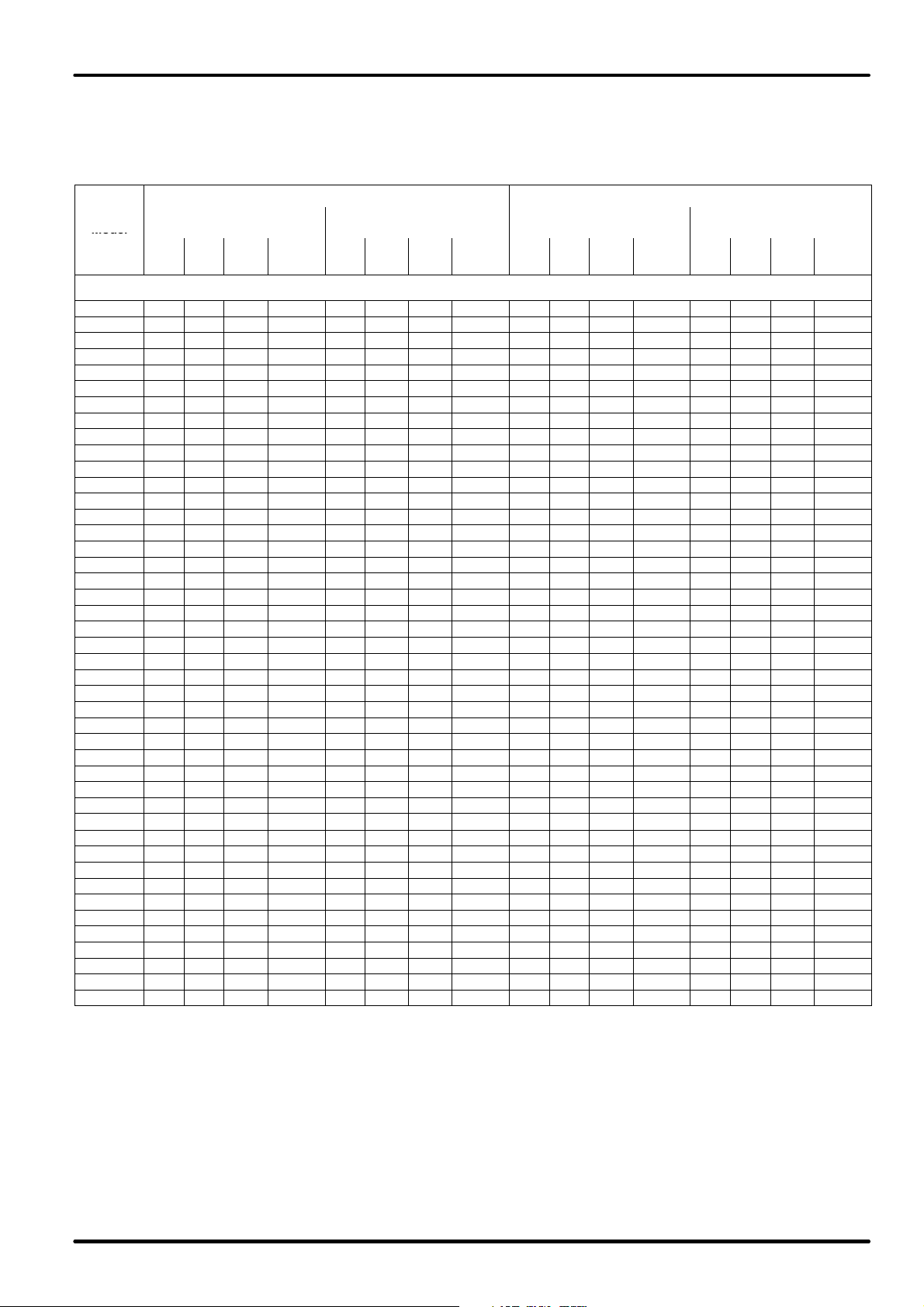
7 - Electrical characteristics
50 Hz / R 22
STANDARD POWER SUPPLY OPTIONAL POWER SUPPLY
FAN
Model
OA FLA LRA
(*)
4MUA
4SUA/W
4LUA/W 2.6 3.8 4.4 0.6 3.8 5.5 38.5 2.0 2.6 3.8 4.4 0.6 6.6 10.9 80.9 2.0
6SUA/W 2.6 4.5 8.0 0.4 4.5 6.3 43.5 2.5 2.6 6.5 5.5 0.4 7.8 12.4 91.4 2.5
6LUA/W 3.3 4.5 8.0 0.5 5.9 7.5 51.0 2.9 3.3 6.5 5.5 0.5 10.2 14.8 108.0 2.9
8SUA/W 4.5 6.8 11.0 0.9 5.9 7.5 51.0 2.9 4.5 6.8 11.0 0.9 10.2 14.8 108.0 2.9
8LUA/W 5.4 6.8 11.0 1.2 7.4 9.6 59.5 3.6 5.4 6.8 11.0 1.2 12.8 19.1 136.0 3.6
5SUA/W
5LUA/W 2.6 x 2 3.8 x 2 4.4 x 2 1.21 3.8 x 2 5.5 x 2 38.5 x 2 4.0 2.6 x 2 3.8 x 2 4.4 x 2 1.2 6.6 x 2 10.9x 2 80.9x 2 4.0
7SUA/W 2.6 x 2 4.5 x 2 8.0 x 2 0.8 4.5 x 2 6.3 x 2 43.5 x 2 5.0 2.6 x 2 6.5 x 2 5.5 x 2 0.8 7.8 x 2 12.4x 2 91.4x 2 5.0
7LUA/W 3.3 x 2 4.5 x 2 8.0 x 2 1.0 5.9 x 2 7.5 x 2 51.0 x 2 5.8 3.3 x 2 6.5 x 2 5.5 x 2 1.0 10.2x 2 14.8x 2 108.0x2 5.8
9SUA/W 4.5 x 2 6.8 x 2 11.0 x 2 1.8 5.9 x 2 7.5 x 2 51.0 x 2 5.8 4.5 x 2 6.8 x 2 11.0 x 2 1.8 10.2x 2 14.8x 2 108.0x2 5.8
9LUA/W 5.4 x 2 6.8 x 2 11.0 x 2 2.4 7.4 x 2 9.6 x 2 59.5 x 2 7.2 5.4 x 2 6.8 x 2 11.0 x 2 2.4 12.8x 2 19.1x 2 136.0x2 7.2
4MOA
4SOA/W
4LOA/W 2.5 3.8 4.4 0.5 3.8 5.5 38.5 2.0 2.5 3.8 4.4 0.5 6.6 10.9 80.9 2.0
6SOA/W 2.2 4.5 8.0 0.3 4.5 6.3 43.5 2.5 2.2 4.5 8.0 0.3 7.8 12.4 91.4 2.5
6LOA/W 3.1 4.5 8.0 0.5 5.9 7.5 51.0 2.9 3.1 4.5 8.0 0.5 10.2 14.8 108.0 2.9
8SOA/W 3.9 6.8 11.0 0.8 5.9 7.5 51.0 2.9 3.9 6.8 11.0 0.8 10.2 14.8 108.0 2.9
8LOA/W 4.7 6.8 11.0 1.1 7.4 9.6 59.5 3.6 4.7 6.8 11.0 1.1 12.8 19.1 136.0 3.6
4SCA/W
4LCA/W 2.4 3.8 4.4 0.6 3.8 5.5 38.5 2.1 2.4 3.8 4.4 0.6 6.6 10.9 80.9 2.1
6SCA/W 2.2 4.5 8.0 0.4 4.5 6.3 43.5 2.5 2.2 4.5 8.0 0.4 7.8 12.4 91.4 2.5
8SCA/W 4.2 6.8 11.0 0.8 5.9 7.5 51.0 2.9 4.2 6.5 11.0 0.8 10.2 14.8 108.0 2.9
5SOA/W
5LOA/W 2.5 x 2 3.8 x 2 4.4 x 2 1.0 3.8 x 2 5.5 x 2 38.5 x 2 4.0 2.5 x 2 3.8 x 2 4.4 x 2 1.0 6.6 x 2 10.9x 2 80.9x 2 4.0
7SOA/W 2.2 x 2 4.5 x 2 8.0 x 2 0.6 4.5 x 2 6.3 x 2 43.5 x 2 5.0 2.2 x 2 4.5 x 2 8.0 x 2 0.6 7.8 x 2 12.4x 2 91.4x 2 5.0
7LOA/W 3.1 x 2 4.5 x 2 8.0 x 2 1.0 5.9 x 2 7.5 x 2 51.0 x 2 5.8 3.1 x 2 4.5 x 2 8.0 x 2 1.0 10.2x 2 14.8x 2 108.0x2 5.8
9SOA/W 3.9 x 2 6.8 x 2 11.0 x 2 1.6 5.9 x 2 7.5 x 2 51.0 x 2 5.8 3.9 x 2 6.8 x 2 11.0 x 2 1.6 10.2x 2 14.8x 2 108.0x2 5.8
9LOA/W 4.7 x 2 6.8 x 2 11.0 x 2 2.2 7.4 x 2 9.6 x 2 59.5 x 2 7.2 4.7 x 2 6.8 x 2 11.0 x 2 2.2 12.8x 2 19.1x 2 136.0x2 7.2
4LUC 2.6 3.8 4.4 0.6 2.6 3.8 4.4 0.6
6LUC 3.3 4.5 8.0 0.5 3.3 4.5 8.0 0.5
8LUC 5.4 6.8 11.0 1.2 5.4 6.5 11.0 1.2
4LOC 2.5 3.8 4.4 0.5 2.5 3.8 4.4 0.5
6LOC 3.1 4.5 8.0 0.5 3.1 4.5 8.0 0.5
8LOC 4.7 6.8 11.0 1.1 4.7 6.5 11.0 1.1
8LUD/H 5.0 6.8 11.0 1.1 7.3 9.6 59.5 3.6 5.0 6.5 11.0 1.1 12.6 19.1 136.0 3.6
8LOD/H 4.5 6.8 11.0 1.0 7.3 9.6 59.5 3.6 4.5 6.5 11.0 1.0 12.6 19.1 136.0 3.6
8LUF 5.0 6.8 11.0 1.1 8.1 9.6 59.5 4.4 5.0 6.5 11.0 1.1 14.0 19.1 136.0 4.4
8LOF 4.5 6.8 11.0 1.0 8.0 9.6 59.5 4.4 4.5 6.5 11.0 1.0 13.9 19.1 136.0 4.4
9LUD/H 5.0 x 2 6.8 x 2 11.0 x 2 2.2 7.3 x 2 9.6 x 2 59.5 x 2 7.2 5.0 x 2 6.5 x 2 11.0 x 2 2.2 12.6x 2 19.1x 2 136.0x2 7.2
9LOD/H 4.5 x 2 6.8 x 2 11.0 x 2 2.0 7.3 x 2 9.6 x 2 59.5 x 2 7.2 4.5 x 2 6.5 x 2 11.0 x 2 2.0 12.6x 2 19.1x 2 136.0x2 7.2
9LUF 5.0 x 2 6.8 x 2 11.0 x 2 2.2 8.1 x 2 9.6 x 2 59.5 x 2 8.8 5.0 x 2 6.5 x 2 11.0 x 2 2.2 14.0x 2 19.1x 2 136.0x2 8.8
9LOF 4.5 x 2 6.8 x 2 11.0 x 2 2.0 8.0 x 2 9.6 x 2 59.5 x 2 8.8 4.5 x 2 6.5 x 2 11.0 x 2 2.0 13.9x 2 19.1x 2 136.0x2 8.8
1.2 1.6 2.9 0.3 6.0 8.7 36.5 1.4 1.2 1.6 2.9 0.3 6.0 8.7 36.5 1.4
(*)
1.4 2.1 3.1 0.3 6.5 10.9 45.0 1.4 1.4 2.1 3.1 0.3 6.5 10.9 45.0 1.4
(*)
1.4 x 2 2.1 x 2 3.1 x 2 0.6 6.5 x 2 10.9 x 2 45.0 x 2 2.8 1.4 x 2 2.1 x 2 3.1 x 2 0.6 6.5 x 2 10.9x 2 45.0x 2 2.8
(*)
0.9 1.6 2.9 0.2 6.0 8.7 36.5 1.4 0.9 1.6 2.9 0.2 6.0 8.7 36.5 1.4
(*)
1.2 2.1 3.1 0.3 6.5 10.9 45.0 1.4 1.2 2.1 3.1 0.3 6.5 10.9 45.0 1.4
(*)
1.4 2.1 3.1 0.3 6.5 10.9 45.0 1.4 1.4 2.1 3.1 0.3 6.5 10.9 45.0 1.4
(*)
1.2 x 2 2.1 x 2 3.1 x 2 0.6 6.5 x 2 10.9 x 2 45.0 x 2 2.8 1.2 x 2 2.1 x 2 3.1 x 2 0.6 6.5 x 2 10.9x 2 45.0x 2 2.8
1ph - 230V
operating
power
(kW)
COMPRESSOR
3ph - 400V
OA FLA LRA
STANDARD R 22
operating
power
(kW)
FAN
1ph - 230V
OA FLA LRA
operating
power
(kW)
COMPRESSOR
3ph - 230V
OA FLA LRA
operating
power
(kW)
22 All Versions
English

50 Hz / R 407C
Model
STANDARD POWER SUPPLY OPTIONAL POWER SUPPLY
FAN
Model
OA FLA LRA
(*)
4PUA/W
4GUA/W 2.6 3.8 4.4 0.6 4.2 5.5 38.5 2.2 2.6 3.8 4.4 0.6 7.3 10.9 80.9 2.2
6PUA/W 2.6 4.5 8.0 0.4 4.8 6.3 43.5 2.5 2.6 6.5 5.5 0.4 8.3 12.4 91.4 2.5
6GUA/W 3.3 4.5 8.0 0.5 6.0 7.5 51.0 3.1 3.3 6.5 5.5 0.5 10.4 14.8 108.0 3.1
8PUA/W 4.5 7.0 7.1 0.9 6.0 7.5 51.0 3.1 4.5 7.0 7.1 0.9 10.4 14.8 108.0 3.1
8GUA/W 5.4 7.0 7.1 1.2 7.6 9.6 59.5 3.8 5.4 7.0 7.1 1.2 13.1 19.1 136.0 3.8
5PUA/W
5GUA/W 2.6 x 2 3.8 x 2 4.4 x 2 1.2 4.2 x 2 5.5 x 2 38.5 x 2 4.4 2.6 x 2 3.8 x 2 4.4 x 2 1.2 7.3 x 2 10.9x 2 80.9x 2 4.4
7PUA/W 2.6 x 2 4.5 x 2 8.0 x 2 0.8 4.8 x 2 6.3 x 2 43.5 x 2 5.0 2.6 x 2 6.5 x 2 5.5 x 2 0.8 8.3 x 2 12.4x 2 91.4x 2 5.0
7GUA/W 3.3 x 2 4.5 x 2 8.0 x 2 1.0 6.0 x 2 7.5 x 2 51.0 x 2 6.2 3.3 x 2 6.5 x 2 5.5 x 2 1.0 10.4x 2 14.8x 2 108.0x2 6.2
9PUA/W 4.5 x 2 7.0 x 2 7.1 x 2 1.8 6.0 x 2 7.5 x 2 51.0 x 2 6.2 4.5 x 2 7.0 x 2 7.1 x 2 1.8 10.4x 2 14.8x 2 108.0x2 6.2
9GUA/W 5.4 x 2 7.0 x 2 7.1 x 2 2.4 7.6 x 2 9.6 x 2 59.5 x 2 7.6 5.4 x 2 7.0 x 2 7.1 x 2 2.4 13.1x 2 19.1x 2 136.0x2 7.6
4POA/W
4GOA/W 2.5 3.8 4.4 0.5 4.2 5.5 38.5 2.2 2.5 3.8 4.4 0.5 7.3 10.9 80.9 2.2
6POA/W 2.2 4.5 8.0 0.3 4.8 6.3 43.5 2.5 2.2 6.5 5.5 0.3 8.3 12.4 91.4 2.5
6GOA/W 3.1 4.5 8.0 0.5 6.0 7.5 51.0 3.1 3.1 6.5 5.5 0.5 10.4 14.8 108.0 3.1
8POA/W 3.9 6.8 11.0 0.8 6.0 7.5 51.0 3.1 3.9 7.0 7.1 0.8 10.4 14.8 108.0 3.1
8GOA/W 4.7 6.8 11.0 1.1 7.6 9.6 59.5 3.8 4.7 7.0 7.1 1.1 13.1 19.1 136.0 3.8
4PCA/W
4GCA/W 2.4 3.8 4.4 0.6 4.2 5.5 38.5 2.2 2.4 3.8 4.4 0.6 7.3 10.9 80.9 2.2
6PCA/W 2.2 4.5 8.0 0.4 4.8 6.3 43.5 2.5 2.2 4.5 8.0 0.4 8.3 12.4 91.4 2.5
8PCA/W 4.2 6.8 11.0 0.8 6.0 7.5 51.0 3.1 4.2 6.8 11.0 0.8 10.4 14.8 108.0 3.1
5POA/W
5GOA/W 2.5 x 2 3.8 x 2 4.4 x 2 1.0 4.2 x 2 5.5 x 2 38.5 x 2 4.4 2.5 x 2 3.8 x 2 4.4 x 2 1.0 7.3 x 2 10.9x 2 80.9x 2 4.4
7POA/W 2.2 x 2 4.5 x 2 8.0 x 2 0.6 4.8 x 2 6.3 x 2 43.5 x 2 5.0 2.2 x 2 6.5 x 2 5.5 x 2 0.6 8.3 x 2 12.4x 2 91.4x 2 5.0
7GOA/W 3.1 x 2 4.5 x 2 8.0 x 2 1.0 6.0 x 2 7.5 x 2 51.0 x 2 6.2 3.1 x 2 6.5 x 2 5.5 x 2 1.0 10.4x 2 14.8x 2 108.0x2 6.2
9POA/W 3.9 x 2 6.8 x 2 11.0 x 2 1.6 6.0 x 2 7.5 x 2 51.0 x 2 6.2 3.9 x 2 7.0 x 2 7.1 x 2 1.6 10.4x 2 14.8x 2 108.0x2 6.2
9GOA/W 4.7 x 2 6.8 x 2 11.0 x 2 2.2 7.6 x 2 9.6 x 2 59.5 x 2 7.6 4.7 x 2 7.0 x 2 7.1 x 2 2.2 13.1x 2 19.1x 2 136.0x2 7.6
8GUD/H 5.0 6.8 11.0 1.1 7.6 9.6 59.5 3.8 5.0 6.8 11.0 1.1 13.1 19.1 136.0 3.8
8GOD/H 4.5 6.8 11.0 1.0 7.6 9.6 59.5 3.8 4.5 6.8 11.0 1.0 13.1 19.1 136.0 3.8
8GUF 5.0 6.8 11.0 1.1 8.6 9.6 59.5 4.7 5.0 6.8 11.0 1.1 14.9 19.1 136.0 4.7
8GOF 4.5 6.8 11.0 1.0 8.5 9.6 59.5 4.6 4.5 6.8 11.0 1.0 14.7 19.1 136.0 4.6
9GUD/H 5.0 x 2 6.8 x 2 11.0 x 2 2.2 7.6 x 2 9.6 x 2 59.5 x 2 7.6 5.0 x 2 6.8 x 2 11.0 x 2 2.2 13.1x 2 19.1x 2 136.0x2 7.6
9GOD/H 4.5 x 2 6.8 x 2 11.0 x 2 2.0 7.6 x 2 9.6 x 2 59.5 x 2 7.6 4.5 x 2 6.8 x 2 11.0 x 2 2.0 13.1x 2 19.1x 2 136.0x2 7.6
9GUF 5.0 x 2 6.8 x 2 11.0 x 2 2.2 8.6 x 2 9.6 x 2 59.5 x 2 9.4 5.0 x 2 6.8 x 2 11.0 x 2 2.2 14.9x 2 19.1x 2 136.0x2 9.4
9GOF 4.5 x 2 6.8 x 2 11.0 x 2 2.0 8.5 x 2 9.6 x 2 59.5 x 2 9.2 4.5 x 2 6.8 x 2 11.0 x 2 2.0 14.7x 2 19.1x 2 136.0x2 9.2
1.4 2.1 3.1 0.3 6.8 10.9 45.0 1.5 1.4 2.1 3.1 0.3 6.8 10.9 45.0 1.5
(*)
1.4 x 2 2.1 x 2 3.1 x 2 0.6 6.8 x 2 10.9 x 2 45.0 x 2 3.0 1.4 x 2 2.1 x 2 3.1 x 2 0.6 6.8 x 2 10.9x 2 45.0x 2 3.0
(*)
1.2 2.1 3.1 0.3 6.8 10.9 45.0 1.5 1.2 2.1 3.1 0.3 6.8 10.9 45.0 1.5
(*)
1.4 2.1 3.1 0.3 6.8 10.9 45.0 1.5 1.4 2.1 3.1 0.3 6.8 10.9 45.0 1.5
(*)
1.2 x 2 2.1 x 2 3.1 x 2 0.6 6.8 x 2 10.9 x 2 45.0 x 2 3.0 1.2 x 2 2.1 x 2 3.1 x 2 0.6 6.8 x 2 10.9x 2 45.0x 2 3.0
1ph - 230V
operating
power
(kW)
1) Fan OA is for standard unit operating at the standard pressure drop.
2) Compressor OA is referred to - room conditions: 24C, 50% RH; condensing temperature: 45C. A/W/D/H models
3) Compressor OA is referred to - room conditions: 24C, 50% RH; ext. temperature: 35C. F models
4) Compressor FLA is for the contemporary conditions of minimum evaporating pressure and maximum condensing pressures.
COMPRESSOR
3ph - 400V
OA FLA LRA
OPTIONAL R 407C
operating
power
(kW)
FAN
1ph - 230V
OA FLA LRA
operating
power
(kW)
COMPRESSOR
3ph - 230V
OA FLA LRA
Hiflex
operating
power
(kW)
English
23All Versions

Hiflex
Model
60 Hz / R 22
FAN
1ph - 230V
OA FLA LRA
operating power
(kW)
OA FLA LRA
STANDARD R 22
4MUA 1.5 1.5 2.7 0.3 6.0 10.3 36.5 1.7 230/1/60
4SUA/W 2.3 2.9 4.3 0.5 6.5 11.4 56.0 1.7 208-230/1/60
4LUA/W 4.3 4.8 5.6 1.0 6.6 11.4 83.0 2.5 200-230/3/60
6SUA/W 3.7 5.4 9.6 0.7 7.8 13.4 95.0 3.0 200-230/3/60
6LUA/W 4.0 5.4 9.6 0.8 5.9 7.8 57.0 3.5 380/3/60
8SUA/W 5.9 7.0 11.3 1.3 5.9 7.8 57.0 3.5 380/3/60
8LUA/W 7.1 7.0 11.3 1.6 7.4 10.7 64.0 4.3 380/3/60
5SUA/W 2.3 x 2 2.9 x 2 4.3 x 2 1.0 6.5 x 2 11.4 x 2 56.0 x 2 3.4 208-230/1/60
5LUA/W 4.3 x 2 4.8 x 2 5.6 x 2 2.0 6.6 x 2 11.4 x 2 83.0 x 2 5.0 200-230/3/60
7SUA/W 3.7 x 2 5.4 x 2 9.6 x 2 1.4 7.8 x 2 13.4 x 2 95.0 x 2 6.0 200-230/3/60
7LUA/W 4.0 x 2 5.4 x 2 9.6 x 2 1.6 5.9 x 2 7.8 x 2 57.0 x 2 7.0 380/3/60
9SUA/W 5.9 x 2 7.0 x 2 11.3 x 2 2.6 5.9 x 2 7.8 x 2 57.0 x 2 7.0 380/3/60
9LUA/W 7.1 x 2 7.0 x 2 11.3 x 2 3.2 7.4 x 2 10.7 x 2 64.0 x 2 8.6 380/3/60
4MOA 1.2 1.5 2.7 0.2 5.9 10.3 36.5 1.7 230/1/60
4SOA/W 2.1 2.9 4.3 0.5 6.5 11.4 56.0 1.7 208-230/1/60
4LOA/W 4.1 4.8 5.6 1.0 6.6 11.4 83.0 2.5 200-230/3/60
6SOA/W 3.3 5.4 9.6 0.7 7.8 13.9 95.0 3.0 200-230/3/60
6LOA/W 3.7 5.4 9.6 0.8 5.9 7.8 57.0 3.5 380/3/60
8SOA/W 5.1 7.0 11.3 1.1 5.9 7.8 57.0 3.5 380/3/60
8LOA/W 6.2 7.0 11.3 1.4 7.4 10.7 64.0 4.3 380/3/60
4SCA/W 1.9 2.9 4.3 0.4 6.5 11.4 56.0 1.7 208-230/1/60
4LCA/W 3.9 4.8 5.6 1.0 6.6 11.4 83.0 2.5 200-230/3/60
6SCA/W 2.5 6.4 9.6 0.5 7.8 13.9 95.0 3.0 200-230/3/60
8SCA/W 4.6 7.0 11.3 1.1 5.9 7.8 57.0 3.5 380/3/60
5SOA/W 2.1 x 2 2.9 x 2 4.3 x 2 3.0 6.5 x 2 11.4 x 2 56.0 x 2 3.4 208-230/1/60
5LOA/W 4.1 x 2 4.8 x 2 5.6 x 2 2.0 6.6 x 2 11.4 x 2 83.0 x 2 5.0 200-230/3/60
7SOA/W 3.3 x 2 5.4 x 2 9.6 x 2 1.4 7.8 x 2 13.9 x 2 95.0 x 2 6.0 200-230/3/60
7LOA/W 3.7 x 2 5.4 x 2 9.6 x 2 1.6 5.9 x 2 7.8 x 2 57.0 x 2 7.0 380/3/60
9SOA/W 5.1 x 2 7.0 x 2 11.3 x 2 2.2 5.9 x 2 7.8 x 2 57.0 x 2 7.0 380/3/60
9LOA/W 6.2 x 2 7.0 x 2 11.3 x 2 2.8 7.4 x 2 10.7 x 2 64.0 x 2 8.6 380/3/60
4LUC 4.3 4.8 5.6 1.0
6LUC 4.0 5.4 9.6 0.8
8LUC 7.1 7.0 11.3 1.6
4LOC 4.1 4.8 5.6 1.0
6LOC 3.7 6.4 9.6 0.8
8LOC 6.2 7.0 11.3 1.4
8LUD/H 6.6 7.0 11.3 1.5 7.3 10.7 64.0 4.4 380/3/60
8LOD/H 5.8 7.0 11.3 1.4 7.2 10.7 64.0 4.4 380/3/60
8LUF 6.6 7.0 11.3 1.5 8.7 10.7 64.0 5.2 380/3/60
8LOF 5.8 7.0 11.3 1.4 8.7 10.7 64.0 5.2 380/3/60
9LUD/H 6.6 x 2 7.0 x 2 11.3 x 2 3.0 7.3 x 2 10.7 x 2 64.0 x 2 8.8 380/3/60
9LOD/H 5.8 x 2 7.0 x 2 11.3 x 2 2.8 7.2 x 2 10.7 x 2 64.0 x 2 8.8 380/3/60
9LUF 6.6 x 2 7.0 x 2 11.3 x 2 3.0 8.8 x 2 10.7 x 2 64.0 x 2 10.4 380/3/60
9LOF 5.8 x 2 7.0 x 2 11.3 x 2 2.8 8.8 x 2 10.7 x 2 64.0 x 2 10.4 380/3/60
COMPRESSOR
operating power
(kW)
power supply
(V/ph/Hz)
24 All Versions
English

60 Hz / R 407C
Model
FAN
1ph - 230V
OA FLA LRA
operating power
(kW)
OA FLA LRA
OPTIONAL R 407C
4PUA/W 2.3 2.9 4.3 0.5 6.8 11.4 56.0 1.7 208-230/1/60
4GUA/W 4.3 4.8 5.6 1.0 7.3 11.4 83.0 2.6 200-230/3/60
6PUA/W 3.7 5.4 9.6 0.7 8.3 13.9 95.0 3.0 200-230/3/60
6GUA/W 4.0 5.4 9.6 0.8 6.0 7.8 57.0 3.7 380/3/60
8PUA/W 5.9 7.0 11.3 1.3 6.0 7.8 57.0 3.7 380/3/60
8GUA/W 7.1 7.0 11.3 1.6 7.6 10.7 64.0 4.6 380/3/60
5PUA/W 2.3 x 2 2.9 x 2 4.3 x 2 1.0 6.8 x 2 11.4 x 2 56.0 x 2 3.4 208-230/1/60
5GUA/W 4.3 x 2 4.8 x 2 5.6 x 2 2.0 7.3 x 2 11.4 x 2 83.0 x 2 5.2 200-230/3/60
7PUA/W 3.7 x 2 5.4 x 2 9.6 x 2 1.4 8.3 x 2 13.9 x 2 95.0 x 2 6.0 200-230/3/60
7GUA/W 4.0 x 2 5.4 x 2 9.6 x 2 1.6 6.0 x 2 7.8 x 2 57.0 x 2 7.4 380/3/60
9PUA/W 5.9 x 2 7.0 x 2 11.3 x 2 2.6 6.0 x 2 7.8 x 2 57.0 x 2 7.4 380/3/60
9GUA/W 7.1 x 2 7.0 x 2 11.3 x 2 3.2 7.6 x 2 10.7 x 2 64.0 x 2 9.2 380/3/60
4POA/W 2.1 2.9 4.3 0.5 6.8 11.4 56.0 1.8 208-230/1/60
4GOA/W 4.1 4.8 5.6 1.0 7.3 11.4 83.0 2.6 200-230/3/60
6POA/W 3.3 5.4 9.6 0.7 8.3 13.9 95.0 3.0 200-230/3/60
6GOA/W 3.7 5.4 9.6 0.8 6.0 7.8 57.0 3.7 380/3/60
8POA/W 5.1 7.0 11.3 1.1 6.0 7.8 57.0 3.7 380/3/60
8GOA/W 6.2 7.0 11.3 1.4 7.6 10.7 64.0 4.6 380/3/60
4PCA/W 1.9 2.9 4.3 0.4 6.8 11.4 56.0 1.8 208-230/1/60
4GCA/W 2.9 4.8 5.6 1.0 7.3 11.4 83.0 2.6 200-230/3/60
6PCA/W 3.9 5.4 9.6 0.5 8.3 13.9 95.0 3.0 200-230/3/60
8PCA/W 4.6 7.0 11.3 1.1 6.0 7.8 57.0 3.7 380/3/60
5POA/W 2.1 x 2 2.9 x 2 4.3 x 2 1.0 6.8 x 2 11.4 x 2 56.0 x 2 3.6 208-230/1/60
5GOA/W 4 x 2.1 4.8 x 2 5.6 x 2 2.0 7.3 x 2 11.4 x 2 83.0 x 2 5.2 200-230/3/60
7POA/W 3.3 x 2 5.4 x 2 9.6 x 2 1.4 8.3 x 2 13.9 x 2 95.0 x 2 6.0 200-230/3/60
7GOA/W 3.7 x 2 5.4 x 2 9.6 x 2 1.6 6.0 x 2 7.8 x 2 57.0 x 2 7.4 380/3/60
9POA/W 5.1 x 2 7.0 x 2 11.3 x 2 2.2 6.0 x 2 7.8 x 2 57.0 x 2 7.4 380/3/60
9GOA/W 6.2 x 2 7.0 x 2 11.3 x 2 2.8 7.6 x 2 10.7 x 2 64.0 x 2 9.2 380/3/60
8GUD/H 6.6 7.0 11.3 1.5 7.6 10.7 64.0 4.6 380/3/60
8GOD/H 5.8 7.0 11.3 1.4 7.6 10.7 64.0 4.6 380/3/60
8GUF 6.6 7.0 11.3 1.5 7.5 10.7 64.0 5.5 380/3/60
8GOF 5.8 7.0 11.3 1.4 7.5 10.7 64.0 5.5 380/3/60
9GUD/H 6.6 x 2 7.0 x 2 11.3 x 2 3.0 7.6 x 2 10.7 x 2 64.0 x 2 9.2 380/3/60
9GOD/H 5.8 x 2 7.0 x 2 11.3 x 2 2.8 7.6 x 2 10.7 x 2 64.0 x 2 9.2 380/3/60
9GUF 6.6 x 2 7.0 x 2 11.3 x 2 3.0 7.5 x 2 10.7 x 2 64.0 x 2 11.0 380/3/60
9GOF 5.8 x 2 7.0 x 2 11.3 x 2 2.8 7.5 x 2 10.7 x 2 64.0 x 2 11.0 380/3/60
1) Fan OA is for standard unit operating at the standard pressure drop.
2) Compressor OA is referred to - room conditions: 24C, 50% RH; condensing temperature: 45C. A/W/D/H models
3) Compressor OA is referred to - room conditions: 24C, 50% RH; ext. temperature: 35C. F models
4) Compressor FLA is for the contemporary conditions of minimum evaporating pressure and maximum condensing pressure.
COMPRESSOR
operating power
(kW)
Hiflex
power supply
(V/ph/Hz)
English
25All Versions

Hiflex
Model
MODEL
COMPONENTS
H P
F A N
OPTIONAL
400 V/3 ph/50-60 Hz 230 V/3 ph/50-60 Hz
Electrical heating Humidifier Electrical heating Humidifier
FLA
power
FLA
[kW]
nominal
(*)
(*)
6.5 4.5 6.5 1.5 11.3 4.5 6.5 1.5
6.5 4.5 6.5 1.5 11.3 4.5 6.5 1.5
4S/P/M U/O/C A/W
4L/G U/O/C A/W/C
6S/P U/O/C A/W 6.5 4.5 5.0 3.4 11.3 4.5 8.1 3.4
6L/G U/O A/W/C 6.5 4.5 5.0 3.4 11.3 4.5 8.1 3.4
8S/P U/O A/W 6.5 4.5 5.0 3.4 11.3 4.5 8.1 3.4
8L/G U/O A/W/F/D/H/C 6.5 4.5 5.0 3.4 11.3 4.5 8.1 3.4
5S/P U/O A/W
5L/G U/O A/W/C
(*)
(*)
6.5 x 2 9.0 6.5 3.0 11.3 x 2 9.0 6.5 3.0
6.5 x 2 9.0 6.5 3.0 11.3 x 2 9.0 6.5 3.0
7S/P U/O A/W 6.5 x 2 9.0 5.0 6.8 11.3 x 2 9.0 8.1 6.8
7L/G U/O A/W/C 6.5 x 2 9.0 5.0 6.8 11.3 x 2 9.0 8.1 6.8
9S/P U/O A/W 6.5 x 2 9.0 5.0 6.8 11.3 x 2 9.0 8.1 6.8
9L/G U/O A/W/F/D/H/C 6.5 x 2 9.0 5.0 6.8 11.3 x 2 9.0 8.1 6.8
Electrical heating values are for maximum heating (3 steps).
(*) The humidifiers in the models 4 M and 4Sx and 4Lx are single-phase (230V/1ph/50-60 Hz)
nominal
power
[kW]
FLA
nominal
power
[kW]
FLA
nominal
power
[kW]
CONFIGURATION WITH OPTIONAL FANS TYPE HPFan"
POWER SUPPLY 230-400/3/50 + N POWER SUPPLY 230-380/3/60 + N
OA FLA LRA OA FLA LRA
4S/P/M U A/W
4S/P/M O A/W
4S/P C A/W
4L/G U A/W/C
4L/G O A/W/C
4L/G C A/W
6S/P U A/W
6S/P O A/W
6S/P C A/W
6L/G U A/W/C
6L/G O A/W/C
8S/P U A/W
8S/P O A/W
8S/P C A/W
8L/G U
A/W/C/D/F/H
8L/G O
A/W/C/D/F/H
5S/P U A/W
5S/P O A/W
5L/G U A/W/C
5L/G O A/W/C
7S/P U A/W
7S/P O A/W
7L/G U A/W/C
7L/G O A/W/C
9S/P U A/W
9S/P O A/W
9L/G U
A/W/C/D/F/H
9L/G O
A/W/C/D/F/H
Fan OA is for standard unit operating at the standard pressure drop.
2.4 3.2 6.5 3.72 4.3
2.3 3.2 6.5 3.48 4.3
3.2 6.5 3.01 4.3
2.9 3.2 6.5 4.82 6.3
2.8 3.2 6.5 5.03 6.3
3.2 6.5 4.86 6.3
5.3 6.5 12.0 5.71 6.3
5.6 6.5 12.0 5.51 6.3
6.5 12.0 5.11 6.3
5.4 6.5 12.0 6.09 6.3
5.6 6.5 12.0 5.89 6.3
7.5 9.4 17.0
7.6 9.4 17.0
7.6 9.4 17.0
7.8 9.4 17.0
2.4 x 2 3.2 x 2 6.5 x 2 3.72 x 2 4.3 x 2
2.3 x 2 3.2 x 2 6.5 x 2 3.48 x 2 4.3 x 2
2.9 x 2 3.2 x 2 6.5 x 2 4.82 x 2 6.3 x 2
2.8 x 2 6.5 x 2 6.5 x 2 5.03 x 2 6.3 x 2
5.3 x 2 6.5 x 2 12.0 x 2 5.71 x 2 6.3 x 2
5.6 x 2 6.5 x 2 12.0 x 2 5.51 x 2 6.3 x 2ì
5.4 x 2 6.5 x 2 12.0 x 2 6.09 x 2 6.3 x 2
5.6 x 2 6.5 x 2 12.0 x 2 5.89 x 2 6.3 x 2
7.5 x 2 9.4 x 2 17.0 x 2
7.6 x 2 9.4 x 2 17.0 x 2
7.6 x 2 9.4 x 2 17.0 x 2
7.8 x 2 9.4 x 2 17.0 x 2
17.0
26 All Versions
English
 Loading...