

Page 1

Liebert®
GXT5™ UPS
Installer/User Guide
200 V to 240 V, 5,000 VA to 20,000 VA
Page 2

The information contained in this document is subject to change
without notice and may not be suitable for all applications. While
every precaution has been taken to ensure the accuracy and
completeness of this document, Vertiv assumes no responsibility
and disclaims all liability for damages resulting from use of this
information or for any errors or omissions. Refer to other local
practices or building codes as applicable for the correct methods,
tools, and materials to be used in performing procedures not
specifically described in this document.
The products covered by this instruction manual are manufactured
and/or sold by Vertiv. This document is the property of Vertiv and
contains confidential and proprietary information owned by Vertiv.
Any copying, use or disclosure of it without the written permission
of Vertiv is strictly prohibited.
Names of companies and products are trademarks or registered
trademarks of the respective companies. Any questions regarding
usage of trademark names should be directed to the original
manufacturer.
Technical Support Site
If you encounter any installation or operational issues with your product, check the pertinent
section of this manual to see if the issue can be resolved by following outlined procedures.
Visit https://www.VertivCo.com/en-us/support/ for additional assistance.
Vertiv | Liebert® GXT5™ Installer/User G uide
Page 3

TABLE OF CONTENTS
Important Safety Information 1
1 GXT5 Description 3
1.1 UPS Features and Available Models 3
1.2 Front Panels 4
1.3 Rear Panels 4
1.4 Removable Power-distribution Boxes 10
1.5 Internal Battery Packs 12
1.6 Major Internal Components and Operating Principle 13
1.6.1 Maintenance Bypass 14
1.7 UPS States and Operating Modes 14
1.7.1 Normal Mode 14
1.7.2 Bypass Mode 15
1.7.3 Battery Mode 16
1.7.4 ECO Mode 17
1.7.5 Maintenance Bypass Mode 18
2 Installation 21
2.1 Unpacking and Inspection 21
2.2 Pre-installation Preparation 21
2.2.1 Installation Clearances 21
2.3 Installing the UPS 22
2.3.1 Tower Installation 22
2.3.2 Rack Installation 22
2.4 Installing External Battery Cabinets 23
2.5 Installing a Power-distribution Box 24
2.6 Hardwired Input/Output Connections 25
2.6.1 Branch Circuit Breaker 26
2.6.2 Terminal-block Connections 27
2.6.3 Connecting to Terminal Blocks on 5-kVA and 6-kVA models 29
2.6.4 Connecting to Terminal Blocks on 8-kVA and 10-kVA models 29
2.6.5 Connecting to Terminal Blocks on 16-kVA and 20-kVA models 30
2.7 Communication Connections 32
2.7.1 Connecting IntelliSlot Communication 32
2.7.2 Connecting to the Dry-contact Port 32
2.7.3 Connecting a Remote Emergency Power-off (REPO) Switch 33
2.7.4 Connecting a USB Cable 34
2.7.5 Connecting CLI Communication Cables 35
2.7.6 Connecting Sensors to the Control Port 35
2.8 Installing a Parallel System 35
2.8.1 First-time Start-up of Parallel System 37
2.8.2 Commissioning Parallel System 37
Vertiv | Liebert® GXT5™ Installer/User Guide | iii
Page 4

2.8.3 Adding a Single UPS to the Parallel System 38
3 Operating the UPS 39
3.1 Silencingthe Audible Alarm 39
3.2 Starting-up the UPS 39
3.3 Transferring to Battery Mode 39
3.4 Transferring from Normal to Bypass Mode 40
3.5 Transferring from Bypass to Normal Mode 40
3.6 Shutting-down the UPS Completely 40
3.7 Remote Emergency Power-off (REPO) 40
4 Operation and Display Panel 41
4.1 LED Indicators 42
4.2 LCD Menu and Screens 43
4.2.1 Start-up and Flow Screens 43
4.2.2 Main Menu 43
4.3 Editing Display and Operation Settings 51
4.3.1 Changing the Password 51
4.3.2 Selecting the Display Language 52
4.3.3 Setting the Date and Time 52
5 Maintenance 53
5.1 Replacing Batteries 53
5.2 Charging Batteries 55
5.3 Checking UPS Operation 56
5.4 Cleaning the UPS 56
5.5 Removing the Power-distribution Box 56
6 Troubleshooting 59
6.1 Symptoms that Require Troubleshooting 59
6.2 Audible Alarm (Buzzer) 59
6.2.1 Faults 59
6.3 Troubleshooting UPS Issues 60
7 Specifications 61
7.1 Battery Run Times 69
Appendices 73
Appendix A: Technical Support 73
Vertiv | Liebert® GXT5™ Installer/User Guide | iv
Page 5

IMPORTANT SAFETY INFORMATION
IMPORTANT! This manual contains important safety instructions that must be followed during the
installation and maintenance of the UPS and batteries. Read this manual thoroughly and the safety and
regulatory information, available at https://www.vertivco.com/ComplianceRegulatoryInfo, before
attempting to install, connect to supply, or operate this UPS.
1
Page 6

This page intentionally left blank
2
Vertiv | Liebert® GXT5™ Installer/User G uide
Page 7

1 GXT5 DESCRIPTION
The Liebert® GXT5 is a compact, online uninterruptible power system (UPS) that continuously conditions
and regulates its output voltage. The Liebert® GXT5 supplies microcomputers and other sensitive
equipment with clean sine-wave input power.
Upon generation, AC power is clean and stable. However, during transmission and distribution it is subject
to voltage sags, spikes, and complete failure that may interrupt computer operations, cause data loss, and
damage equipment.
The Liebert® GXT5 protects equipment from these disturbances. The Liebert® GXT5 continuously
charges its batteries from the mains, enabling it to supply power to connected loads, even when the mains
fail.
1.1 UPS Features and Available Models
The GXT5 includes the following features. Table 1.1 on the next page, lists the available models and
power ratings.
• Enhanced load capacity with an output power factor of 1.
• Optional tower or rack installation to meet varying installation requirements.
• Parallel-connection capability for 10-kVA, 16-kVA, and 20-kVA models achieves up to 2 + 1
parallel redundant power.
• Adapts to areas with unstable power-mains supply via high-frequency double-conversion
topology structure, with high input-power factor, wide input-voltage range, and output
immune to grid interference.
• Full digital-control platform and hardware-design platform adapts to unstable mains supply
and load impact
• Programmable terminals with cascade protection on 5-kVA to 10-kVA models protect key
devices when load is heavy.
• Innovative design layout and process greatly increase product reliability.
• Operation and display panel with model-specific color LCD offers simple configuration and
control of the UPS.
• ECO power-supply mode and smart-sleep mode help you save the maximum amount of energy.
1 GXT5 Description
Table 1.1 UPS Models and Power Ratings
MODEL NU MBER NOMINAL POWER RATING
GXT5-5000IRT5UXLN
5kVA/5kWGXT5-5000IRT5UXLE
GXT5-5000HVRT5UXLN
GXT5-6000IRT5UXLN
6kVA/6kW
GXT5-6000IRT5UXLE
GXT5-8000IRT5UXLN
8kVA/8kWGXT5-8000IRT5UXLE
GXT5-8000HVRT5UXLN
3
Page 8
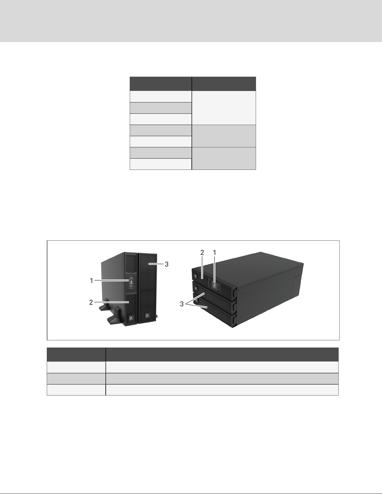
Table 1.1 UPS Models and Power Ratings
(continued)
MODEL NU MBER NOMINAL POWER RATING
GXT5-10KIRT5UXLN
10kVA/10kWGXT5-10KIRT5UXLE
GXT5-10KHVRT5UXLN
GXT5-16KIRT9UXLN
GXT5-16KIRT9UXLE
GXT5-20KIRT9UXLN
GXT5-20KIRT9UXLE
16kVA/16kW
20kVA/20kW
1.2 Front Panels
The various GXT5 models have the same general appearance, with the main difference being the
receptacle types on the rear panel. Figure 1.1 below, shows the 5-kVAto10-kVA model in a tower and a
rack configuration. When mounted in a rack, the 5- to 10-kVA units are turned 90 degrees. The
orientation of the 16-kVA to 20-kVA models is the same in a rack or tower configuration.
Figure 1.1 Front View
ITEM DESCRIPTION
1 Operation/Displaypanel
2 Upper bezel
3 Lower bezel/battery-access door
1.3 Rear Panels
The following figures detail the rear-panel features for each GXT5 model.
4
Vertiv | Liebert® GXT5™ Installer/User G uide
Page 9
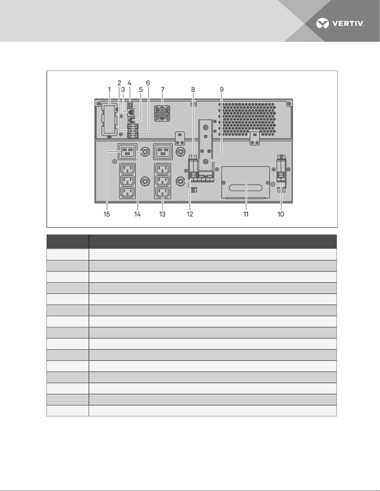
Figure 1.2 GXT5-5000/6000IRT5UXLN (XLE) Rear Panel
ITEM DESCRIPTION
1 Liebert® IntelliSlot™ port
2 Terminal-block communication connectors
3 RS-485 port
4 USB port
5 RS-232 port
6 REPOconnector
7 External-battery-cabinet connector
8 Output circuit breaker
9 Maintenance-bypassbreaker
10 Input circuit breaker
11 Removable POD with cable-entry for hard-wire I/O
12 Overload protector, 10-A (x2)
13 Programmable C13 output receptacles (x2)
14 Overloadprotector, 15-A (x2)
15 C19 output receptacles (x2)
1 GXT5 Description
5
Page 10
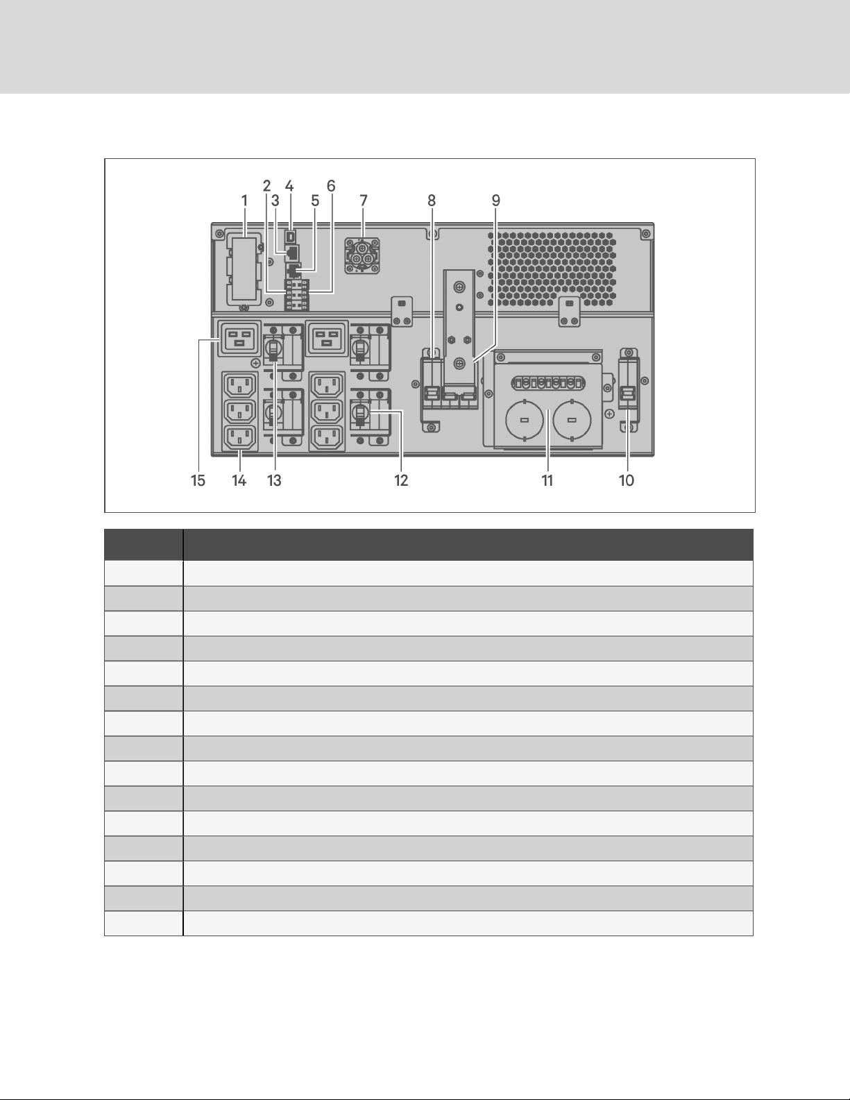
Figure 1.3 GXT5-5000HVRT5UXLN Rear Panel
ITEM DESCRIPTION
1 Liebert® IntelliSlot™ port
2 Terminal-block communication connectors
3 RS-485 port
4 USB port
5 RS-232 port
6 REPOconnector
7 External-battery-cabinet connector
8 Output circuit breaker
9 Maintenance-bypassbreaker
10 Input circuit breaker
11 Removable POD with knock-outs/cable-entry for hard-wire I/O
12 Programmable output circuit breaker, 10-A (x2)
13 C19 output circuit breaker
14 Programmable C13 output receptacles (x2)
15 C19 output receptacles (x2)
6
Vertiv | Liebert® GXT5™ Installer/User G uide
Page 11
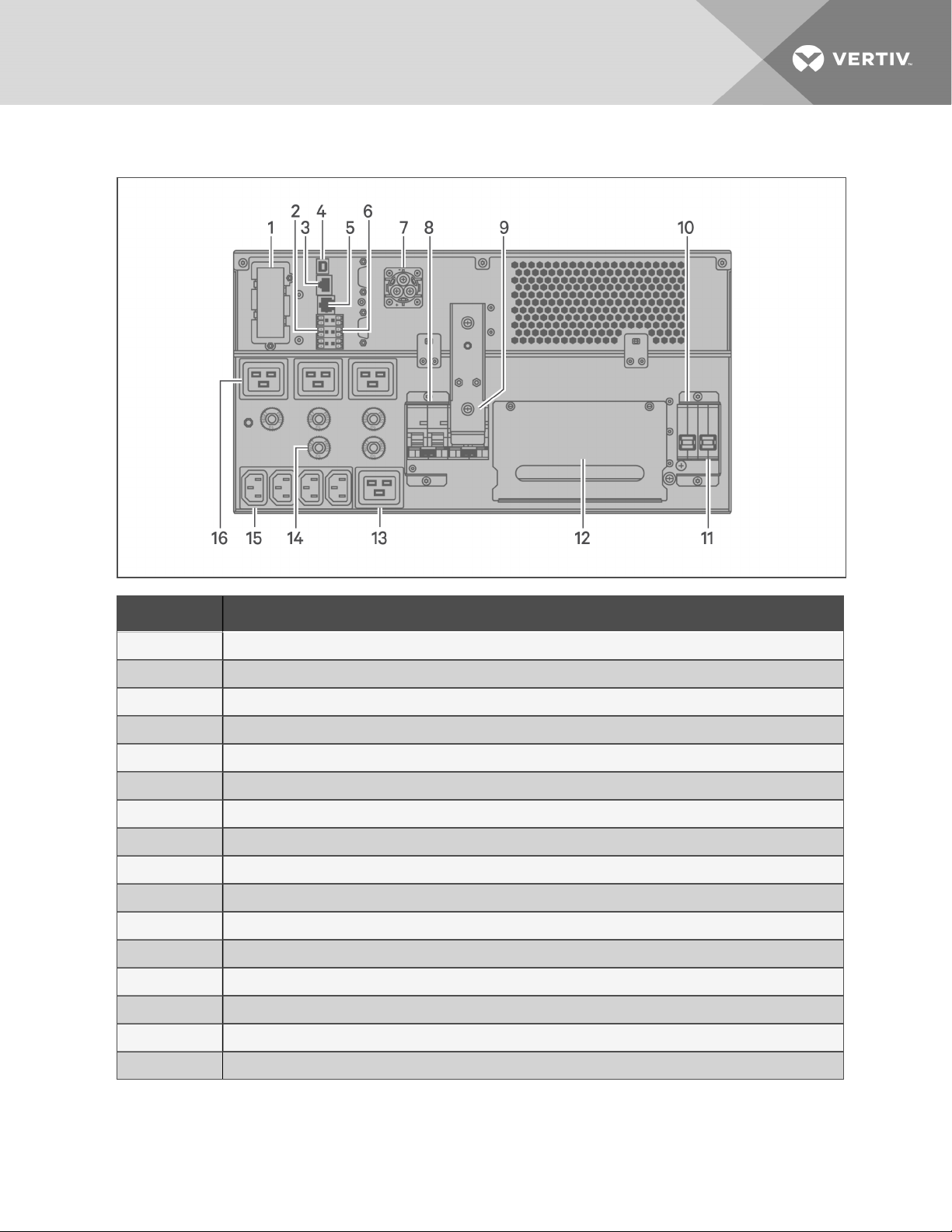
Figure 1.4 GXT5-8000/10KIRT5UXLN (XLE) Rear Panel
ITEM DESCRIPTION
1 Liebert® IntelliSlot™ port
2 Terminal-block communication connectors
3 RS-485 port
4 USB port
5 RS-232 port
6 REPOconnector
7 External-battery-cabinet connector
8 Output circuit breaker
9 Maintenance-bypassbreaker
10 Bypass circuit breaker
11 Input circuit breaker
12 Removable POD with cable-entry for hard-wire I/O
13 Programmable C19 output receptacle
14 Overloadprotector, 10-A
15 Programmable C13 output receptacles
16 Overloadprotector, 15-A (x4)
1 GXT5 Description
7
Page 12
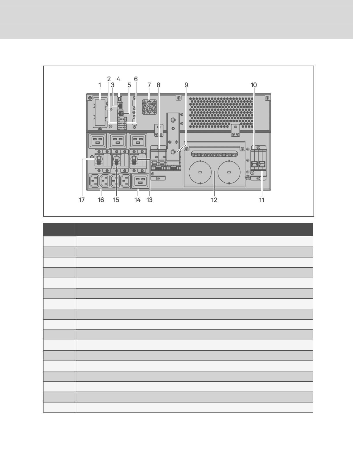
Figure 1.5 GXT5-8000/10KHVRT5UXLN Rear Panel
ITEM DESCRIPTION
1 Liebert® IntelliSlot™ port
2 Terminal-block communication connectors
3 RS-485 port
4 USB port
5 RS-232 port
6 REPOconnector
7 External-battery-cabinet connector
8 Output circuit breaker
9 Maintenance-bypassbreaker
10 Bypass circuit breaker
11 Input circuit breaker
12 Removable POD with knock-outs/cable-entry for hard-wire I/O
13 Programmable output circuit breaker, 15-A
14 Programmable C19 output receptacle
15 Programmable output circuit breaker, 10-A
16 Programmable C13 output receptacles
17 C19 output circuit breaker, 15-A
8
Vertiv | Liebert® GXT5™ Installer/User G uide
Page 13
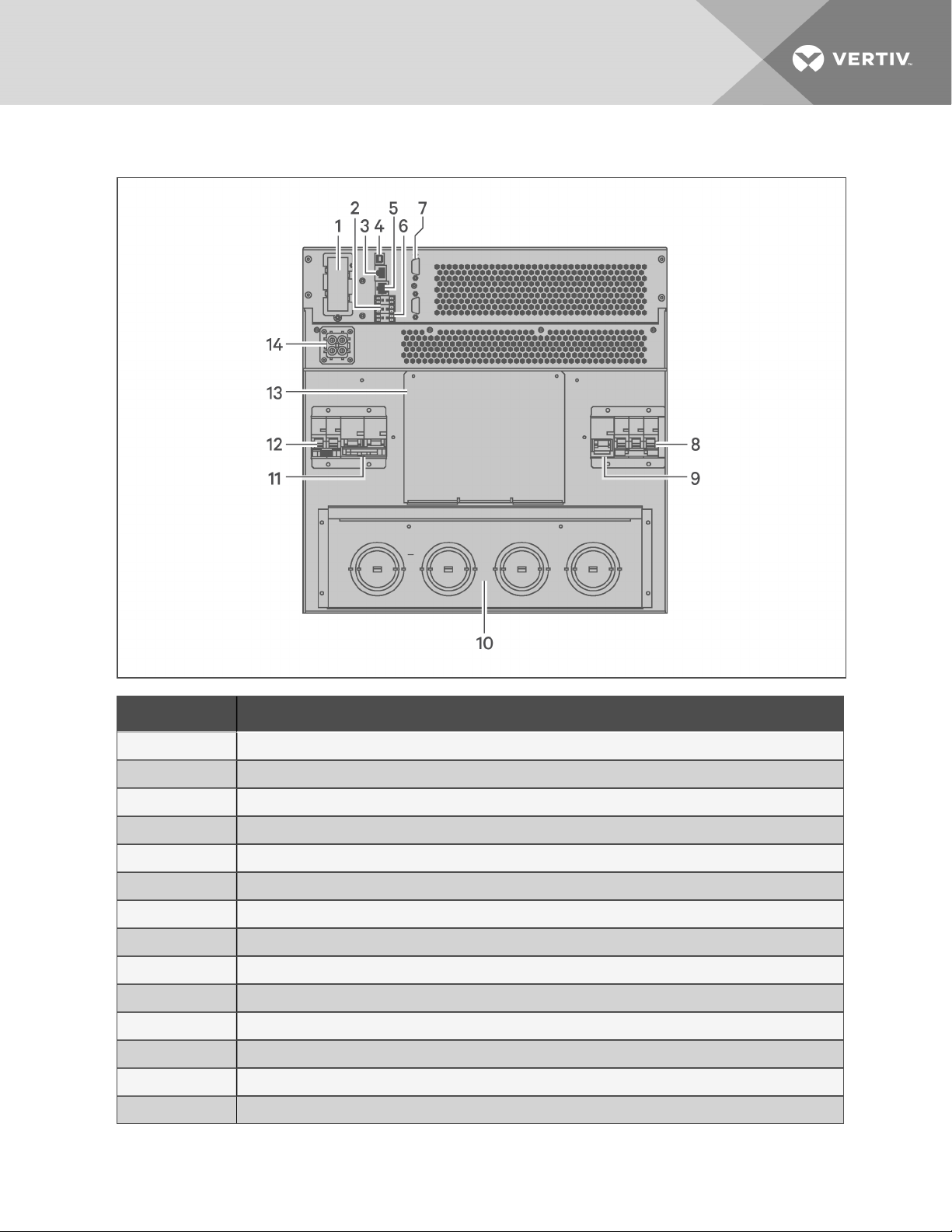
Figure 1.6 GXT5-16K/20KIRT9UXLN (XLE) Rear Panel
ITEM DESCRIPTION
1 Liebert® IntelliSlot™ port
2 Terminal-block communication connectors
3 RS-485 port
4 USB port
5 RS-232 port
6 REPOconnector
7 DB9 ports (parallel communication)
8 Input circuit breaker
9 Bypass circuit breaker
10 Knock-outs/c able-entry for hard-wire I/O
11 Output circuit breaker
12 POD breaker
13 Cover for optionalPOD-installation location
14 External-battery-cabinet connector
1 GXT5 Description
9
Page 14
1.4 Removable Power-distribution Boxes
The 16-kVA and 20-kVA do not ship with an installed power-distribution box (POD). The optional PODs
for the 16-kVA and 20-kVA models models are:
• PD2-108 for models ending in "N"only (North America)
• PD2-200
• PD2-201
• PD2-202
• PD2-204 for models ending in "E"only (European Union)
The 5-kVA to 10-kVA models ship with the POD installed. This POD includes the input circuit breaker for
the UPS, and the features for each POD are detailed in the following figures.
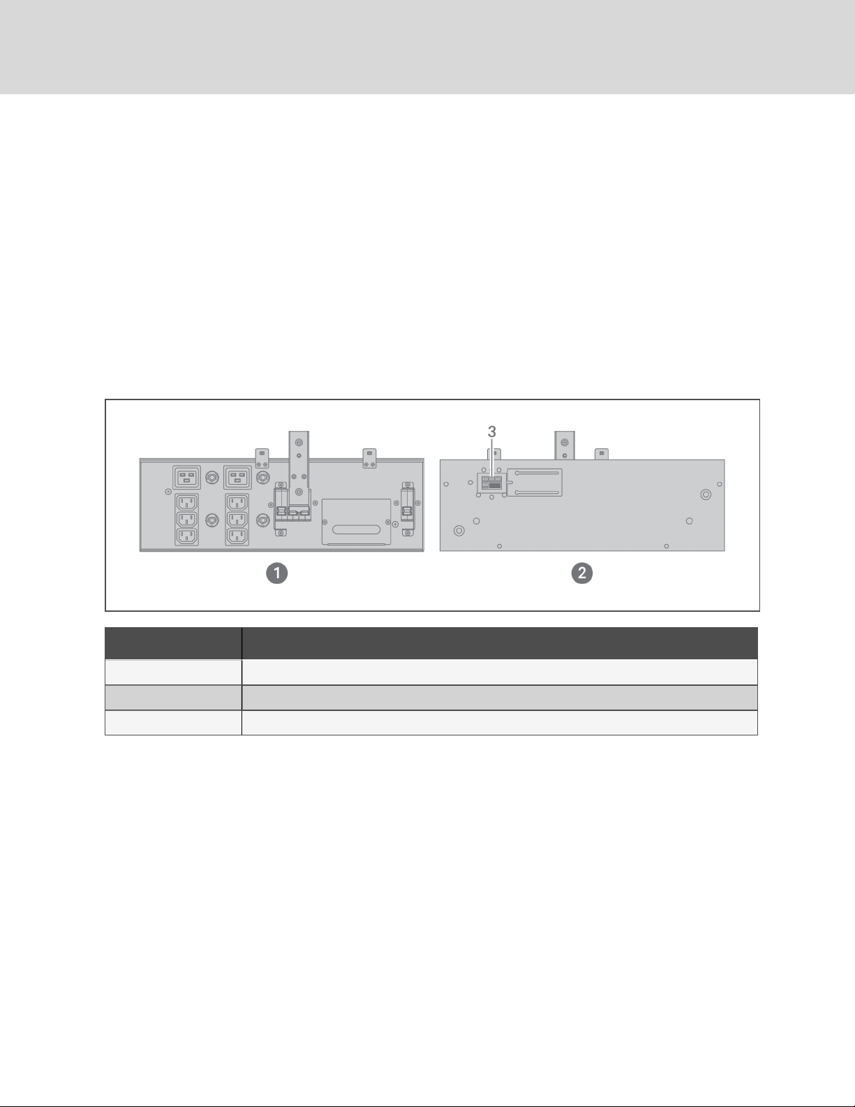
Figure 1.7 PD5-CE6HDWRMBS for GXT5-5000/6000IRT5UXLN (XLE)
ITEM DESCRIPTION
1 PODPanelview (on rear ofunit)
2 POD inner-surface view
3 Quick connect
10
Vertiv | Liebert® GXT5™ Installer/User G uide
Page 15
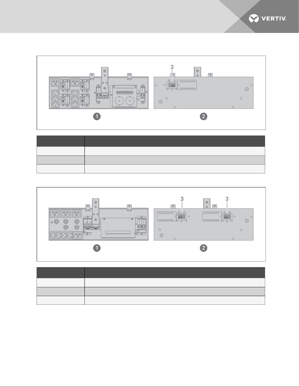
Figure 1.8 PD5-CE6HDWRMBSU for GXT5-5000HVRT5UXLN
ITEM DESCRIPTION
1 PODPanelview (on rear ofunit)
2 POD inner-surface view
3 Quick connect
Figure 1.9 PD5-CE10HDWRMBS for GXT5-8000/10KIRT5UXLN (XLE)
ITEM DESCRIPTION
1 PODPanelview (on rear ofunit)
2 POD inner-surface view
3 Quick connect
1 GXT5 Description
11
Page 16
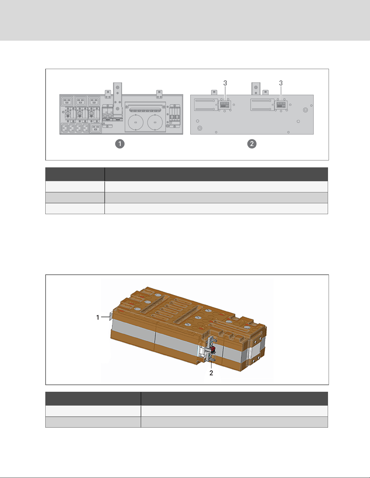
Figure 1.10 PD5-CE10HDWRMBSU for GXT5-8000/10KHVRT5UXLN
ITEM DESCRIPTION
1 PODPanelview (on rear ofunit)
2 POD inner-surface view
3 Quick connect
1.5 Internal Battery Packs
The internal battery packs for all GXT5 models, shown in Figure 1.11 below, are located behind the access
door on the front of the UPS. 5-kVA to 10-kVA units have 2 battery packs, and 16-kVA to 20-kVA units
have 4 battery packs.
Figure 1.11 Internal Battery Pack
ITEM DESCRIPTION
1 Handle
2 Connector
12
Vertiv | Liebert® GXT5™ Installer/User G uide
Page 17
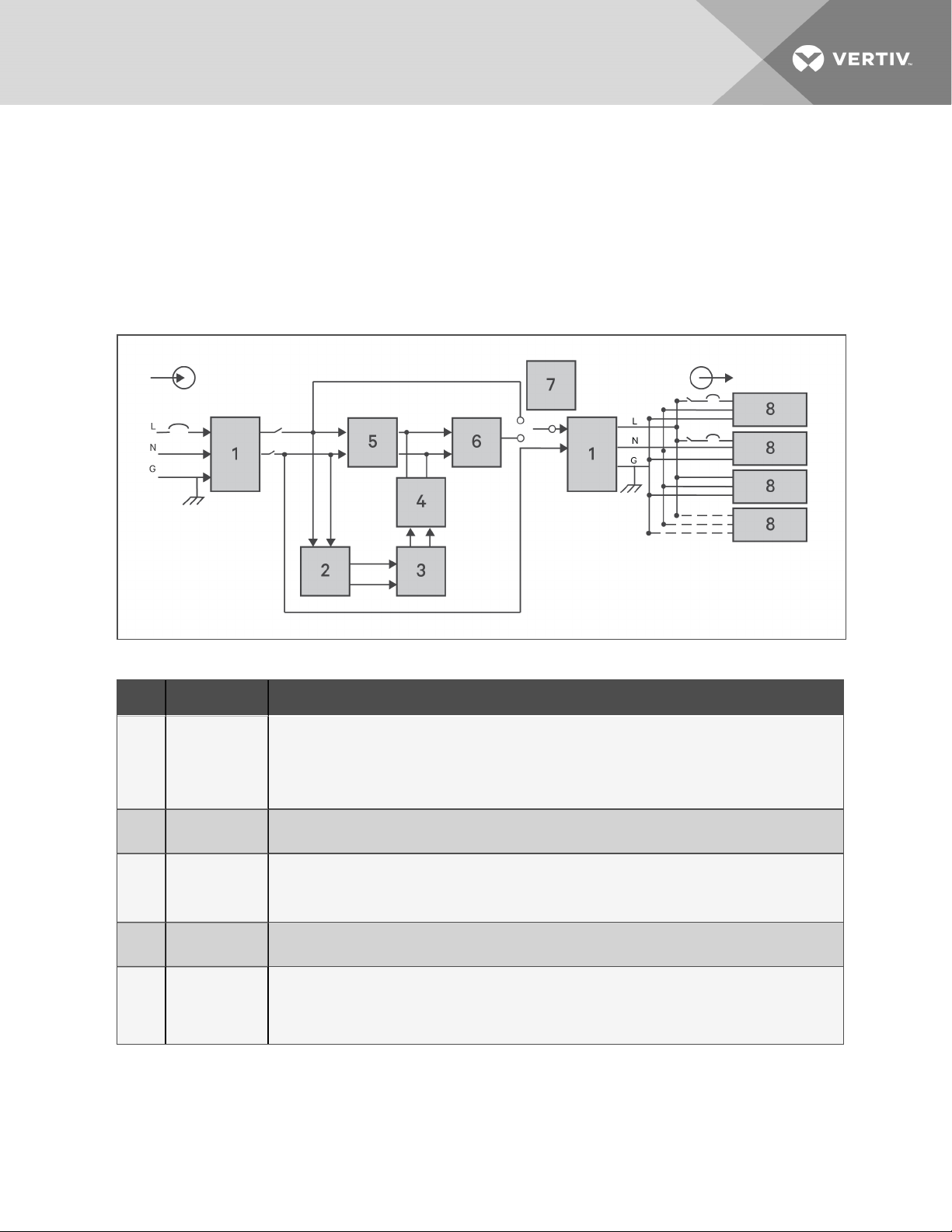
1.6 Major Internal Components and Operating Principle
Figure 1.12 below, shows the UPSoperating principle. Table 1.2 on the next page, describes the function
of the major components in the UPS.
NOTE: Figure 1.12 below, is one example of basic operation. The actual I/O connections for the
various models may be divided into different types. See Hardwired Input/Output Connections on
page25.
Figure 1.12 Basic Operating Principle Diagram
Table 1.2 Major Components
ITEM COMPONENT OPERATION/FUNCTION
Transient
Voltage Surge
1
2 Battery Charger
3 Batteries
4
5
Suppression
(TVSS)and
EMI/RFI Filters
DC-to-DC
Converter
Rectifier/Power
Factor
Correction
(PFC) Circuit
Provide surge protection. Filter electromagnetic interference (EMI) andradio frequency interference
(RFI). Minimize surges or interference present in the utility power and protect devices connected on the
same branch as the UPS.
Continuouslyfloat-charges the batteries from precisely-regulated utility power whenever the UPS is
plugged in.
Valve-regulated, non-spillable, lead-acid batteries.
NOTE: To maintain battery design life, operate the UPS in an ambient temperature of 59°F to 77°F
(15°C to 25°C).
Raises the DC voltage from the battery to the optimum operating voltage for the inverter. This allows the
inverter to operate continuouslyat its optimum efficiency and voltage, thus increasingreliability.
In normal operation, converts utility ACpower to regulated DC power for use bythe inverter while
ensuring that the wave shape of the input current used bythe UPS isnear ideal. Extracting this sine-wave
input current ensures efficient use of utility power and reduces reflected harmonic distortion making
cleaner power available to devices that are not protected bythe UPS.
1 GXT5 Description
13
Page 18

Table 1.2 Major Components (continued)
ITEM COMPONENT OPERATION/FUNCTION
In normal operation, inverts the DC output of the PFC c ircuit into precise, regulated sine-wave AC power.
6 Inverter
7 Internal Bypass
8 Outlet group Output receptacles.
When utility power fails, the inverter receives DC power from the DC-to-DC converter. In either
operating mode, the UPS inverter remains on-line, generating clean, precise, regulated AC-output
power.
In the unlikelyevent of UPS failure such as overload or over-temperature, automatically transfers the
connected load to bypass.
To manually transfer the connected load from inverter to bypass, see Transferring from Normal to
Bypass Mode on page40.
1.6.1 Maintenance Bypass
On 5-kVA to 10-kVA models, the UPS includes manual maintenance bypass in a removable section of the
rear of the UPS. Maintenance bypass keeps connected equipment powered with utility power and allows
replacement of the UPS in the event of a UPS malfunction.
NOTE: The bypass power path does not protect the connected equipment from disturbances in the
utility power supply.
1.7 UPS States and Operating Modes
NOTE: See LED Indicators on page42, for description of the run-indicator and alarm-indicator LEDs
mentioned in this section.
1.7.1 Normal Mode
When utility power is normal, Normal mode employs the rectifier and inverter to provide voltage- and
frequency-stabilized power to the load. The charger charges the battery in normal mode. On the frontpanel display, the run-indicator (green)is On, the alarm indicator is OFF, and the buzzer is silent. Figure
1.13 on the facing page, shows a diagram of normal mode.
14
Vertiv | Liebert® GXT5™ Installer/User G uide
Page 19
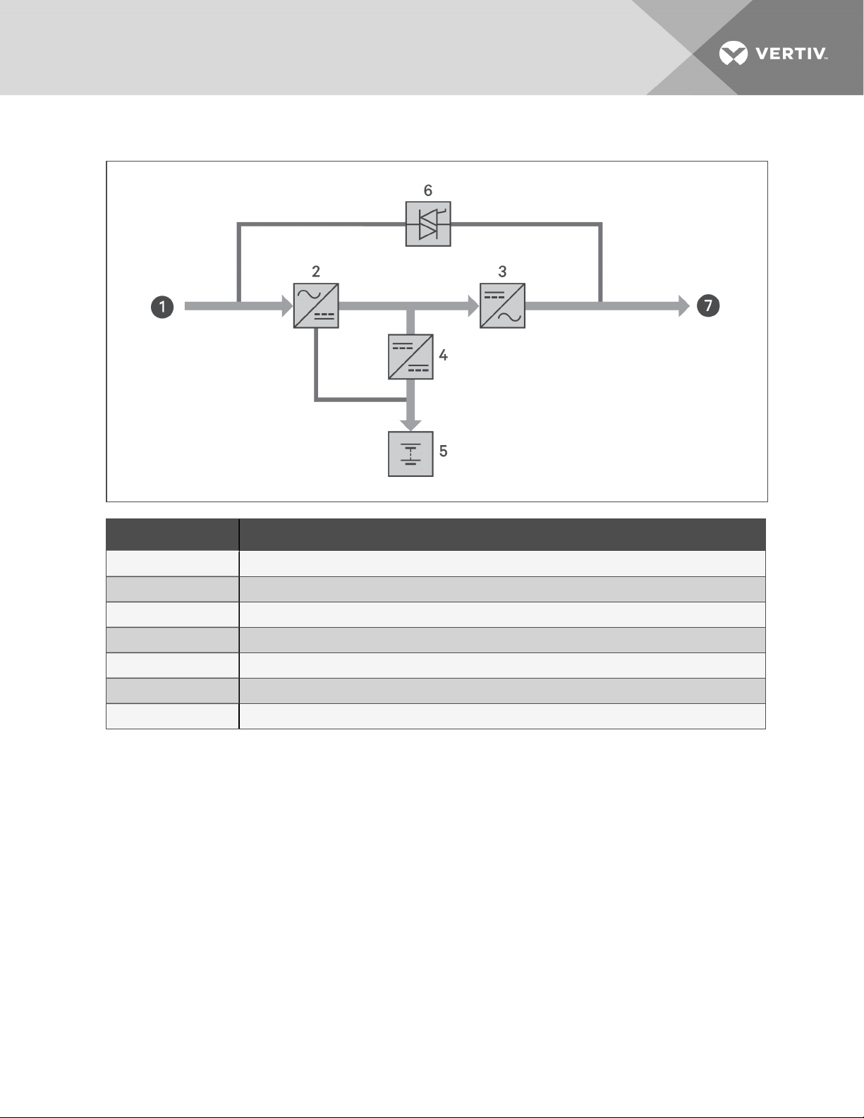
Figure 1.13 Normal-mode Operation
ITEM DESCRIPTION
1 Mains/Utility input (by-pass input)
2 Rectifier/PFC
3 Inverter
4 Battery charger
5 Battery
6 Bypass static switch
7 UPS output
1.7.2 Bypass Mode
Bypass mode supplies power to the load from the bypass source (utility power) if an overload or fault
occurs during normal operation. On the front-panel display, the run indicator (green) is On, the alarm
indicator (yellow)is On, and the buzzer beeps once each seconds. The LCD "Current" screen displays "On
Bypass." Figure 1.14 on the next page, shows a diagram of bypass mode.
NOTE: If utility power fails or if the utility voltage goes outside of the permissible range during bypassmode operation, the UPS shuts down and no output is supplied to the load.
1 GXT5 Description
15
Page 20
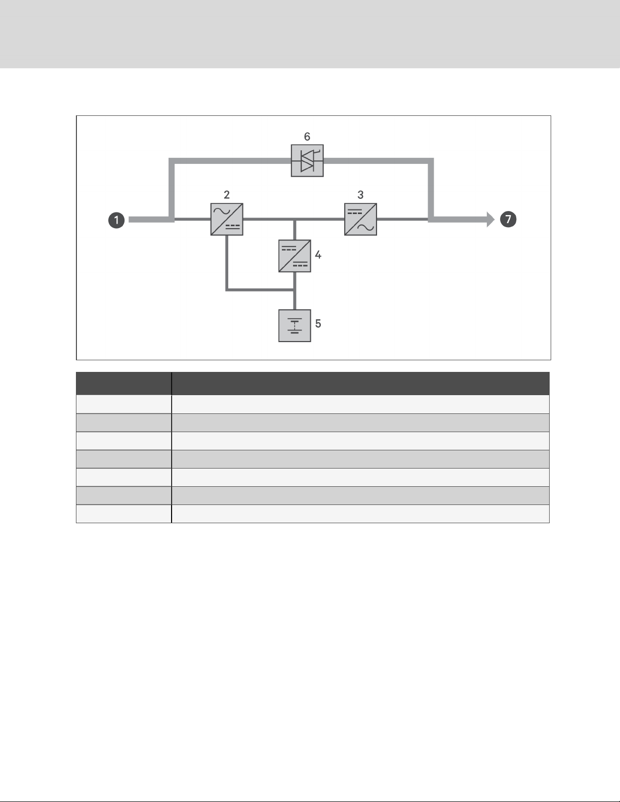
Figure 1.14 Bypass-mode Operation
ITEM DESCRIPTION
1 Mains/Utility input (by-pass input)
2 Rectifier/PFC
3 Inverter
4 Battery charger
5 Battery
6 Bypass static switch
7 UPS output
1.7.3 Battery Mode
Battery mode supplies battery power to the load if utility power fails or if the utility voltage goes outside of
the permissible range. On the front-panel display, the run indicator (green) is On, the alarm indicator
(yellow)is On, and the buzzer beeps once each second. The LCD "Current" screen displays "On Battery."
Figure 1.15 on the facing page, shows a diagram of battery mode.
NOTE: The batteries are fully-charged before shipment. However, transportation and storage
inevitably cause some loss of capacity. To ensure adequate back-up time, charge the batteries for atleast 8 hours before first start-up.
NOTE: If utility power fails and the batteries are charged, you may cold-start the UPS in battery mode
and use battery power to extend system availability for a time.
16
Vertiv | Liebert® GXT5™ Installer/User G uide
Page 21
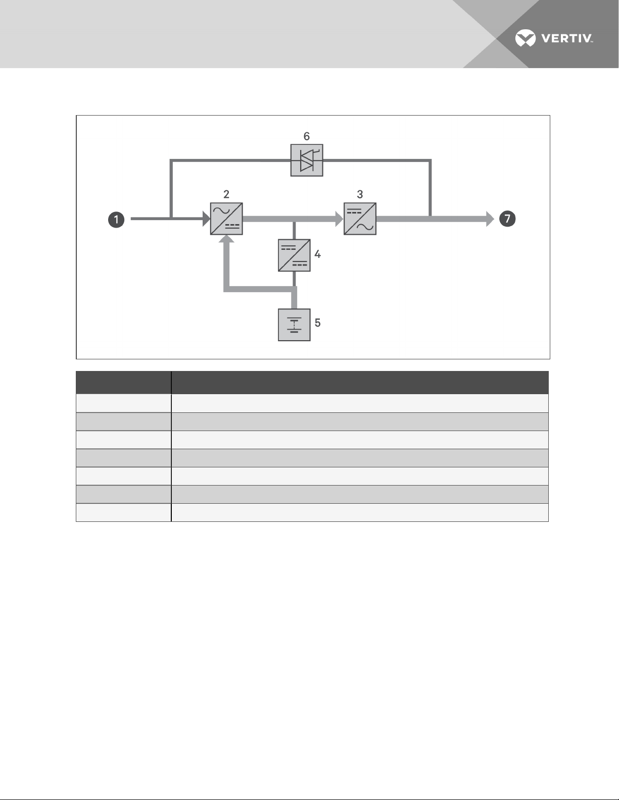
Figure 1.15 Battery-mode Operation
ITEM DESCRIPTION
1 Mains/Utility input (by-pass input)
2 Rectifier/PFC
3 Inverter
4 Battery charger
5 Battery
6 Bypass static switch
7 UPS output
1.7.4 ECO Mode
NOTE: ECO mode is only available on a single-UPS system.
The energy-saving ECO mode reduces power consumption by powering the load via bypass if the bypass
voltage is normal or by powering the load via the inverter when the bypass voltage is abnormal. You can
use ECOmode to power equipment that is not sensitive to power-grid quality to via bypass and reduce
power consumption.
NOTE: During Eco mode, if a bypass-failure or abnormal-bypass-voltage notification appears when the
output is not overloaded, the UPS will transfer to Normal Mode. However, if a notification showing
bypass failure or abnormal bypass voltage appears when the output is overloaded, the UPS will shut
down the bypass.
1 GXT5 Description
17
Page 22

1.7.5 Maintenance Bypass Mode
NOTE: 5-kVA to 10-kVA models include an MCB to switch the load to bypass. On 16-kVA to 20-kVA
models, a dry contact may be used to trigger maintenance bypass.
Used when the UPS requires maintenance or repair, Maintenance-bypass mode powers the connected
equipment with utility power while electrically isolating the internal UPS components.
NOTICE
Risk of power interruption. Can damage the connected equipment.
If utility power fails or if its quality is out of range while the UPS is in Maintenance Bypass Mode,
the UPS may shut down without notice and shut-off output power to the load.
NOTE: The UPS has no user-serviceable parts. If the UPS malfunctions and requires service, visit
http://www.VertivCo.com/en-us/support/ or contact your local Vertiv representative.
18
Vertiv | Liebert® GXT5™ Installer/User G uide
Page 23
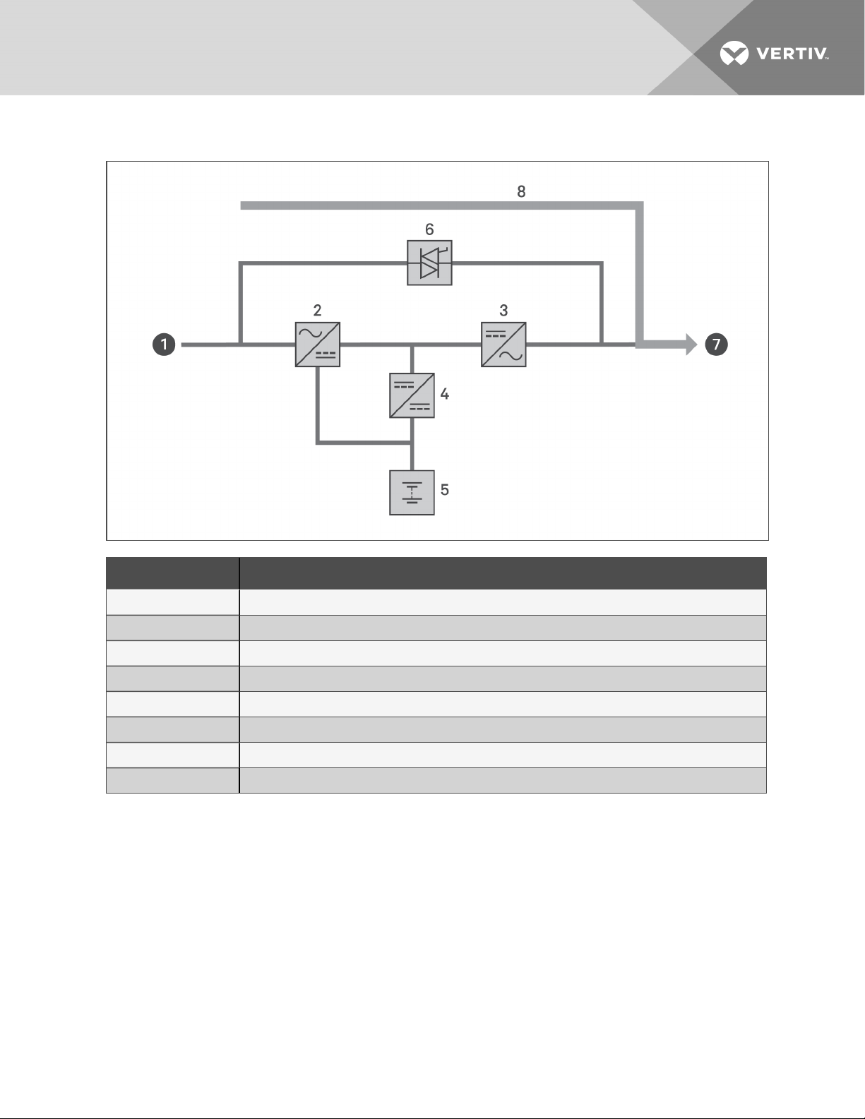
Figure 1.16 Maintenance-bypass Operation
ITEM DESCRIPTION
1 Mains/Utility input (by-pass input)
2 Rectifier/PFC
3 Inverter
4 Battery charger
5 Battery
6 Bypass static switch
7 UPS output
8 Maintenance by-pass
1 GXT5 Description
19
Page 24

This page intentionally left blank
20
Vertiv | Liebert® GXT5™ Installer/User G uide
Page 25

2 INSTALLATION
Do not start the UPS until after the installation is finished, the system is commissioned by an authorized
engineer, and the external-input circuit breakers are closed.
WARNING! Risk of electrical shock. Can cause equipment damage, injury and death. Before
beginning installation, verify that all external overcurrent protection devices are open (Off), and
that they are locked-out and tagged appropriately to prevent activation during the installation,
verify with a voltmeter that power is Off and wear appropriate, OSHA-approved personal
protective equipment (PPE) per NFPA 70E. Failure to comply can cause serious injury or death.
Before proceeding with installation, read all instructions. Follow all local codes.
2.1 Unpacking and Inspection
Unpack the UPS and conduct the following checks:
• Inspect the UPS for shipping damage. If any shipping damage is found, report it to the carrier
and your local Vertiv representative immediately.
• Check the accessories included against the packing list. If there is any discrepancy, contact
your local Vertiv representative immediately.
CAUTION: The UPS is heavy (see Specifications on page61, for the weight). Take proper
precautions when lifting or moving the unit.
2.2 Pre-installation Preparation
• Install the UPS indoors in a controlled environment, where it cannot be accidentally turned Off.
The installation environment should meet the specifications listed in Specifications on page61.
• Place the UPS in an area of unrestricted air-flow around the unit, away from water, flammable
liquids, gases, corrosives, and conductive contaminants. Avoid direct sunlight
NOTE: Operating the UPS in temperatures above 77°F (25°C) reduces battery life.
2.2.1 Installation Clearances
Maintain at least 4in.(100mm) clearance in the front and rear of the UPS. Do not obstruct the air inlets on
the front panel and rear panel of the UPS. Blocking the air inlets reduces ventilation and heat dissipation,
shortening the service life of the unit.
2 Installation
21
Page 26

2.3 Installing the UPS
The UPS may be installed as a tower or in a rack, depending on available space and use considerations.
Determine the type of installation and follow the appropriate instructions. See Tower Installation below or
Rack Installation below.
NOTE: For 16-kVA and 20-kVA models, the unit orientation is the same. See 1.2 on page4, for the
installed position.
NOTE: When installing the UPS or making input and output connections, comply with all relevant
safety codes and standards
2.3.1 Tower Installation
To install the UPS as a tower:
1. Take the support bases out of the accessories box.
Figure 2.1 Support bases
NO. DESCRIPTION
1 Support bases
2 Spacers with connectors
2. If optional, Liebert® external battery cabinets will be connected, take out the spacers shipped
with the battery cabinet.
3. Connect the spacers and the support bases as shown in Figure 2.1 above. Each GXT5 requires
2support bases, one in the front and one in the rear.
4. Place the GXT5 and any battery cabinets on the 2support bases.
2.3.2 Rack Installation
When installed in a rack enclosure, the GXT5 UPS and external battery cabinets (EBC) must be supported
by a shelf or rack-mount rails. Because different rack-mount options install differently, refer to the
installation instructions provided with the rack-mount kit.
CAUTION: The GXT5 is heavy. The UPS must be installed as near the bottom of a rack as
possible. If placed too high, it can make the rack top-heavy and prone to tipping over. For unit
weights, see Specifications on page61.
22
Vertiv | Liebert® GXT5™ Installer/User G uide
Page 27

2.4 Installing External Battery Cabinets
Optional, external battery cabinets (EBC) may be connected to the UPS to provide additional battery run
time. For approximate battery run times with additional EBCs, see Battery Run Times on page69.
External battery cabinets are placed on one side of the UPS in a tower configuration or stacked beneath
the UPS in a rack configuration. Up to 6 EBCs may be connected to the UPS.
WARNING! Risk of electric shock. Can cause injury or death. Disconnect all local and remote
electric power supplies before working with the UPS. Ensure that the unit is shut down and
power has been disconnected before beginning any maintenance.
CAUTION: The external battery cabinet(s) are heavy (see Specifications on page61. Take
proper precautions when lifting them.
To install the EBC(s):
1. Inspect the EBC for freight damage. Report damage to the carrier and your local dealer or
Vertiv representative.
2. For tower installation:
• An additional set of support-base extensions ships with each EBC.
• See the steps in Tower Installation on the previous page, to connect the support
extenders and install the bases.
– or –
For rack installation:
• Rack-mount hardware ships with the EBC.
• Refer to the instructions included with the rack-mount kit to install.
NOTE: Optional slide rails and securing hardware and are sold separately. Please contact your Vertiv
representative for options and Vertiv Technical Support for assistance.
3. Verify the that the EBC breaker is in the "Off" position.
4. Connect the supplied EBC cables to the rear of the cabinet, then to the rear of the UPS, see
Figure 2.2 on the next page.
5. Turn the EBC breaker to the "On" position.
6. Verify the circuit breaker on the EBC is in the "On" position.
The additional back-up run time is enabled.
NOTE: When removing an EBC, turn off the circuit breaker on the rear of the cabinet before
disconnecting the cable.
NOTE: If shipping or storing the UPS for an extended time, disconnect the EBC(s) minimize stand-by
current drain on the batteries and help maintain design life.
2 Installation
23
Page 28

Figure 2.2 EBCs connected to the UPS
ITEM DESCRIPTION
1 EBC-detection dry-contact port (See Table 2.4 on page33, for details.)
2 EBC connector
3 EBC-detection port
4 External battery cabinet
5 Externalbattery cabinet
2.5 Installing a Power-distribution Box
The 5-kVA to 10-kVA models ship with a removable power-distribution box (POD) installed, see Terminal-
block Connections on page27, to make the electrical connections to the UPS. For removal, see the
appropriate procedures in Maintenance on page53.
For 16-kVA to 20-kVA models, the POD ships separately and must be attached to the rear of the UPS. See
Removable Power-distribution Boxes on page10, for the POD options compatible with your GXT5 model.
NOTE: Do not operate the UPS with the POD removed. To shut off all power to the POD and to the load,
utility input power must be disconnected.
24
Vertiv | Liebert® GXT5™ Installer/User G uide
Page 29

To attach the POD on 16-kVA to 20-kVA units:
1. On the rear of the unit, unscrew the two fixing screws from the POD-location cover, see Figure
2.3 below, and remove the cover.
2. Insert the POD receptacles into the ports, and connect the PP75 terminal.
3. Align the POD with the installation hole, then insert and secure the POD.
Figure 2.3 POD-location cover on 16-kVA to 20-kVA models
ITEM DESCRIPTION
1 Fixing screws
2.6 Hardwired Input/Output Connections
WARNING! Risk of electrical shock. Can cause equipment damage, injury and death. Before
beginning installation, verify that all external overcurrent protection devices are open (Off), and
that they are locked-out and tagged appropriately to prevent activation during the installation,
verify with a voltmeter that power is Off and wear appropriate, OSHA-approved personal
protective equipment (PPE) per NFPA 70E. Failure to comply can cause serious injury or death.
Before proceeding with installation, read all instructions. Follow all local codes.
Table 2.1 on the next page, lists the four types of I/O connection are available depending on the UPS
model. Some models offer more than one type.
2 Installation
25
Page 30

Table 2.1 I/O Connection Types by Model
MODEL LINES IN/OUT C ONFIGURATION
5-kVA, 6-kVA 1-in 1-out Common source
8-kVA, 10-kVA 1-in 1-out Common Source or Split bypass
16-kVA, 20-kVA 1-in 1-out or 3-in 1-out Common Source or Split bypass
2.6.1 Branch Circuit Breaker
The installer must provide an upstream branch circuit breaker, see Table 2.2 below, for the ratings. The
input circuit breaker on the distribution box and the output circuit breaker on the rear of the power
distribution box disconnect all power between the main cabinet and the distribution box. Figure 2.4 on
the facing page, shows a diagram of the circuit breakers.
Observe the following guidelines and specifications when making the hard-wire input and output
connections:
• Provide circuit-breaker protection according to local codes. The mains disconnect should be
within sight of the UPS or have an appropriate lock-out.
• Maintain service space around the UPS or use flexible conduit.
• Provide output-distributions panels, circuit-breaker protection, or emergency disconnects
according to local codes.
• Do not install input and output wiring in the same conduit.
Models equipped with a manual bypass breaker pass bypass power directly to the bypass breaker from
the input terminal block. The input circuit breaker on the distribution box does not disconnect power
from the manual bypass breaker.
Table 2.2 Branch
circuitbreakerratings
UNIT RATING MAXIMUM BREAKER RATING
5 kVA
6 kVA
8 kVA
10 kVA
16 kVA
20 kVA
60A
70A
1-phase: 160A
3-phase: 50A
26
Vertiv | Liebert® GXT5™ Installer/User G uide
Page 31

Figure 2.4 Circuit-breakers diagram
ITEM DESC RIPTION
1 Mains/Utility
2 Externalbranch CB
3 Input
4 MB CB
5 Output
6 Input CB
7 Output CB
8 UPS-PFC, battery inverter
2.6.2 Terminal-block Connections
On 5-kVA to 10-kVA models, the hard-wire connections to the terminal blocks are made through
knockouts on the POD attached to the rear of the unit. On 16-kVA to 20-kVA models, the knockouts are
on the rear of the unit. See Removable Power-distribution Boxes on page10, for the location of the
input/output knockouts on your GXT5 model.
Table 2.3 on the next page, details the electrical-connection specifications.
2 Installation
27
Page 32

Table 2.3 Terminal-block electrical specifications
UPS MODEL
GXT5-5000IRT5UXLN
GXT5-5000IRT5UXLE
GXT5-5000HVRT5UXLN
GXT5-6000IRT5UXLN
GXT5-6000IRT5UXLE
GXT5-8000IRT5UXLN
GXT5-8000IRT5UXLE
GXT5-8000HVRTUXLN
GXT5-10KIRT5UXLN
GXT5-10KIRT5UXLE
GXT5-10KHVRT5UXLN
GXT5-16KIRT9UXLN
GXT5-16KIRT9UXLE
GXT5-20KIRT9UXLN
RECOMMENDED
(MAXIMUM)
EXTERNAL
OVERC URRENT
PROTECTION
60A
70A
1-phase: 160A
3-phase: 50A
RECOMMENDED
WIRE SIZE
(INCLUDI NG GROUND
WIRE)
(75°C COPPER WIRE)
10mm2(7 AWG) 16mm2(6AWG) 20in.-lb (2.26Nm)
35mm2(1AWG) 53.5mm2(1/0AWG) 110in.-lb(12.4Nm)
MAXIMUM
WIRE SIZE
ACC EPTED
BY TERMINAL
BLOCK
TERMINAL
TIGHTENING
TORQUE
GXT5-20KIRT9UXLE
To make the terminal-block connections:
1. Loosen the screws from the cable-entry/conduit-box cover, and pull the cables through the
cable-entry hole/knockout leaving some slack for connection.
NOTE: Some UPS models have both a cable-entry hole and knockouts. For EU users, we recommend
that you use the cable-entry hole. However, if you use the knockouts, you must use a suitable cable
and gland or risk electric shock. For North American users, we recommend using the knockouts, and
you must install input and output wiring in separate conduit.
2. Referring to the appropriate terminal-block connection instructions, connect the cables to the
corresponding input/output terminals and use a torque wrench to turn the screw clockwise
until tightened as specified in Table 2.3 above.
• Connecting to Terminal Blocks on 5-kVA and 6-kVA models on the facing page
• Connecting to Terminal Blocks on 8-kVA and 10-kVA models on the facing page
• Connecting to Terminal Blocks on 16-kVA and 20-kVA models on page30
3. Re-install the cable-entry/conduit-box cover, and tighten the screws.
28
Vertiv | Liebert® GXT5™ Installer/User G uide
Page 33

2.6.3 Connecting to Terminal Blocks on 5-kVA and 6-kVA models
These models offer a single type of I/O connection, 1-in 1-out common source. Figure 2.5 below, shows the
terminal block. Refer to the details in Terminal-block Connections on page27, when making the
connections.
Figure 2.5 Terminal Block, 5-kVA and 6-kVA models
ITEM DESCRIPTION
1 Output
2 Input
2.6.4 Connecting to Terminal Blocks on 8-kVA and 10-kVA models
These models offers two types of I/O connection. A single shorting cable ships installed on the on the
terminal block. Refer to the details in Terminal-block Connections on page27, when making the
connections. Figure 2.6 below, shows the shorting cable installed for a split-bypass connection
Figure 2.6 1-in 1-out Split-bypass Connection, 8-kVA and 10-kVA models
ITEM DESCRIPTION
1 Output
2 Bypass
3 Input
4 Shorting cable (installed at factory)
2 Installation
29
Page 34

2.6.5 Connecting to Terminal Blocks on 16-kVA and 20-kVA models
These models offers four types of I/O connection. One shorting cable (W01) ships installed on the terminal
block. Two additional shorting cables are included with the accessories to wire the different types. Refer to
the details in Terminal-block Connections on page27, when making the connections.
• Figure 2.7 below, shows the 3-in 1-out common-source connection
• Figure 2.7 below, shows the 1-in 1-out split-bypass connection.
• Figure 2.7 below, shows the 1-in 1-out common-source connection
Figure 2.7 3-in 1-out Common-source Connection, 16-kVA and 20-kVA models
ITEM DESC RIPTION
1 Output
2 Bypass
3 Input
4 Shorting cable (W01), installed at factory
30
Vertiv | Liebert® GXT5™ Installer/User G uide
Page 35

Figure 2.8 1-in 1-out Split-bypass Connection, 16-kVA and 20-kVA models
ITEM DESCRIPTION
1 Output
2 Bypass
3 Input
4 Shorting cable (W02), included with accessories.
Figure 2.9 1-in 1-out Common-source Connection, 16-kVA and 20-kVA models
ITEM DESC RIPTION
1 Output
2 Bypass
3 Input
4 Shorting cable (W03), included with accessories
2 Installation
31
Page 36

2.7 Communication Connections
The UPS offers several communication interfaces and ports.
NOTE: We recommend that signal-cable lengths be less than 10ft(3m), and are kept away from power
cabling.
2.7.1 Connecting IntelliSlot Communication
The IntelliSlot ports accepts two optional cards:
The Liebert® IntelliSlot™ Relay card (IS-RELAY) card provides dry-contact relay output for custom-wired
applications and delivers support for Trellis® Power Insight™ software.
The Liebert® IntelliSlot™ Unity card (RDU101) provides SNMP and/or RS-485 monitoring of the UPS
across the network and/or building management system and lets you monitor external temperature,
humidity and contact-closure inputs using external sensors.
See the appropriate figure for your model in Rear Panels on page4, for the location of the card port.
To install an IntelliSlot Card:
1. Remove the screws from the slot cover plate and remove the plate.
2. Insert the card into the slot, and secure with the screws that held the cover plate.
To make connections to the card, refer to the Liebert® IntelliSlot™ Installer/User Guide for the appropriate
card available at www.VertivCo.com.
2.7.2 Connecting to the Dry-contact Port
The UPS includes a dry-contact port. See the appropriate figure for your model in Rear Panels on page4,
for the location of the port. Figure 2.10 below, shows the ports and Table 2.4 on the facing page,
describes each port.
The I/O dry contact port capacity is 125Vdc, 0.5A; 30Vdc, 1A
Figure 2.10 Dry-contact Port and Pin Layout
NOTE: Pins 7 and 8 are shorted before delivery.
32
Vertiv | Liebert® GXT5™ Installer/User G uide
Page 37

NOTE: The emergency power-off (EPO) action of the UPS closes the rectifier, inverter and static
bypass, but it cannot disconnect the UPS mains input inside. To completely disconnect the UPS,
disconnect the upstream input circuit breaker when generating the EPO. For details on
REPOconnection and operation, see Connecting a Remote Emergency Power-off (REPO) Switch
below.
Table 2.4 Dry-contact Connection and Pin-out Descriptions
PORT
REPO
PORT
NO.
NAME
1 Input 1
2 Input 2
555
3
Battery
Detection
REPO
Input
5 Output 5
PIN
PIN NAME DESCRIPTION
NO.
Disable/Battery mode
shutdown/Any mode
1
shutdown (Remote Comms
Shutdown)
2 Signal Ground Signal Ground
Disable/Battery mode
shutdown/Any mode
3
shutdown (Remote Comms
Shutdown)
4 Signal Ground Signal Ground
5 EBC Detection (DSCHG)
6 EBC Detection (THR)
7 +5V REPO power supply, 5-Vdc 100-mA
8 REPO Coil -NC
Low Battery/Onbattery/
9
Onbypass/UPSfault
10 SignalGround Signal Ground
Default: Disable, can be set viathe LCD settings page. User can choose
dry contact as NO/NC. when NO, Pin 1and Pin 2 are shorted, the
function isactive. when NC, Pin 1 and Pin 2 are open, the function is
active.
Default: Disable, can be set viathe LCD settings page. User can choose
dry contact as NO/NC. when NO, Pin 1and Pin 2 are shorted, the
function isactive. when NC, Pin 1 and Pin 2 are open, the function is
active.
Default: No EBC User can know the quantity of EBC, when NO, Pin 5 and
Pin 6link to the defective port of EBC .
Default: No EBC User can know the quantity of EBC, when NO, Pin 5 and
Pin 6link to the defective port of EBC .
NC, activated when Pin 7 and Pin 8 is open
NOTE: For details on REPOconnection and operation, see
Connecting a Remote Emergency Power-off (REPO) Switch below.
Default: Low battery, can be set viathe LCD settings page. When the
system has a fault, short Pin 9 and Pin 10
2 Installation
6 Output 6
Low Battery/Onbattery/
11
Onbypass/UPSfault
12 Signal Ground Signal Ground
Default: UPS fault, can be set via the LCD settings page. When the
system has a fault, short Pin 11 andPin 12
2.7.3 Connecting a Remote Emergency Power-off (REPO) Switch
The UPS includes an EPO connection in the dry-contact port. See the appropriate figure for your model in
Rear Panels on page4, for the location of the port.
UPS ships with a REPO jumper installed, allowing the UPS to operate as a normally-closed switch system
(fail-safe). Opening the circuit disables the UPS. To connect a REPOswitch that opens the circuit to shut
down the rectifier and inverter and power-off the UPS, use a cable from the remote switch to plug into the
REPO-port on the UPS.
33
Page 38

In normal conditions, the REPO switch cannot cut off the UPS input power. When the REPO switch trips,
the UPS generates an alarm and immediately cuts-off output power. When the emergency condition is
resolved, the UPS will not return to normal operation until you reset the REPO switch and manually poweron the UPS.
To make the cable for the REPO connection:
Figure 2.11 below, shows the cable required to make the connection. We recommend using 18AWG to
33AWG (0.82mm2to 0.33mm2) copper-core cable.
1. Remove the insulation from the end of two cables.
2. Insert the stripped end into the plug terminals 1 and 2 respectively, then press down the
terminals. Make sure that the cables are secure in the plug to prevent failure because of loose
contact.
To connect a UPS to the REPO switch
CAUTION: To maintain safety (SELV) barriers and electromagnetic compatibility, signal cables
should be shielded and run separately from power cables.
1. Connect one end of the cable to the remote switch, see Figure 2.11 below.
2. Remove the factory-installed jumper from pins 7 and 8 of the dry-contact port on the UPS
3. Connect the plug to pins 7 and 8.
Figure 2.11 Cable/Plug for Connecting REPOswitch to UPS REPO port
ITEM DESC RIPTION
1 Terminal 1
2 Terminal 2
3 Plug (connects to REPO port on UPS)
4 REPO switch
2.7.4 Connecting a USB Cable
The UPS includes a USB connector. See the appropriate figure for your model in Rear Panels on page4,
for the location of the port.
The standard, B-type USB port connects the UPS to a network server or other computer system.
The USB port supports HID/CDC protocol. The CDC protocol is reserved for service software. To use the
HID protocol for monitoring, get the HIDprotocol from www.VertivCo.com.
34
Vertiv | Liebert® GXT5™ Installer/User G uide
Page 39

2.7.5 Connecting CLI Communication Cables
The UPS supports the Vertiv command-line interface for operation with ACS and other third-party
monitoring protocols. The RJ-45 port is used for CLI connection. See the appropriate figure for your model
in Rear Panels on page4, for the location of the port. The pin-out, described in Table 2.5 below, is
consistent with the ACS pin-out.
Table 2.5 RJ-45 Port Pin-out
PIN SIGNAL DIREC TION
1 NC —
2 NC —
3 TXD O
4 GND —
5 NC —
6 RXD |
7 NC —
8 NC —
2.7.6 Connecting Sensors to the Control Port
The UPS supports the Vertiv temperature and temperature/humidity sensors. The RJ-45 port is used for
sensor connection. See the appropriate figure for your model in Rear Panels on page4, for the location of
the port.
When connected, the sensor address must be 1to20.
The GXT5 supports two sensors:
• Liebert® IRM-S01T
• Liebert® IRM-S02TH
2.8 Installing a Parallel System
10-kVA, 16-kVA, and 20-kVA models may be configured in a parallel system. The UPS parallel system
provides N+X(1≤N+X≤3,X=0or1) parallel configuration. Nstands for the basic parallel sets, Xstands
for the redundant sets.
All electrical requirements, including external-distribution panel and branch circuit breaker, apply to
each UPS in a parallel system, which are then connected in ring configuration for redundancy and
additional reliability. System load information can be accessed via any controller/display in the system.
The following are requirements for the parallel-connected system:
• Each UPS must have the same capacity and must be connected to the same mains/utility
source.
• If a residual-current detector (RCD) is required, if must be correctly-set and installed before
the same neutral-line input terminal. See safety and regulatory information, available at
https://www.vertivco.com/ComplianceRegulatoryInfo.
• The output of each ups must be connected to the same output bus.
2 Installation
35
Page 40

• The parameter configuration for each UPS must be identical.
• Because the parallel system is not fitted with auxiliary-contact detection devices for the output
circuit breaker or the maintenance-bypass circuit breaker of each UPS, You must strictly-follow
the procedures for transferring between operating modes when removing a single UPS from
the parallel system before maintenance and when adding a single UPS after maintenance.
Failure to observe the procedure may affect the reliability of the load power supply.
Figure 2.12 below, shows an example of the 10-kVA model connected as a 2+1parallel system connected
in a ring configuration.
NOTE: 8-kVA models do not support parallelling at this time.
NOTE: You must use Vertiv parallel cables for the connection.
NOTE: If a fault occurs during parallel-system operation, shut-off the system and make sure the cables
are connected correctly, see Figure 2.12 below.
CAUTION: Risk of improper disconnection. Can equipment damange. Do not disconnect
parallel-system cables while the system is operating.
Figure 2.12 Connection of 2+1 Parallel System
ITEM DESCRIPTION
1 Upper connector
2 Lower connector
36
Vertiv | Liebert® GXT5™ Installer/User G uide
Page 41

2.8.1 First-time Start-up of Parallel System
IMPORTANT! Do not start the UPS until after the installation is finished, the system is commissioned
by an authorized engineer, and the external input circuit breakers are closed.
CAUTION: Starting the UPS applies mains/utility power to the output terminals. Make sure that
the load power is safe and ready to accept power. If the load is not ready, isolate the load with
the output terminal.
The "Parallel" parameters for each UPS in the system must be set and synchronized at first start-up.
To start and set parameters for the parallel system:
1. Make sure that the output MCBs of all units in the parallel system are open, then close the
input MCB on each UPS.
Each UPS powers on, a self-check screen displays, and the alarm/run indicators are lit for about
5seconds.
2. Wait about 30seconds to allow the rectifier start-up to finish, then at each UPS, set the parallel
parameters as follows:
NOTE: If the "Parallel Comm Fail" Alarm displays, clear it and proceed. Communication should not fail
after the parallel settings are synchronized.
a. On the display, press Enter to display the Main Menu, then use the arrow buttons to
select Settings, and press Enter.
NOTE: To adjust the settings, you must enter a password. See Editing Display and Operation Settings
on page51, for details on entering the password and editing the setting parameters.
b. Use the arrow buttons to select the Parallel tab, then press Enter to display the
parameters list.
c. Select and Enter each parameter setting, and then use last item in the list, Sync parallel
parameters, to validate the settings.
For a full description of UPS display functions and settings, see Operation and Display
Panel on page41.
3. After confirming the parallel parameters and each UPS is operating normally, commission the
parallel system, see Commissioning Parallel System below.
2.8.2 Commissioning Parallel System
CAUTION: When powering-on the parallel system, confirm that the external output MCB for
each UPS is closed and that all of the inverter output is connected in parallel.
CAUTION: To avoid load power failure, confirm that the system is working normally, then feed
power to the load.
2 Installation
37
Page 42

To commission the parallel system:
1. Close the external output MCB and input MCB on each UPS, then wait about 30seconds to
allow the rectifier start-up to finish.
2. At the first UPS, press the power button for 2seconds and note that the run indicator (green)
is lit, then measure the inverter-output voltage and verify that it is normal.
3. Repeat step2 for each UPSin the parallel system.
2.8.3 Adding a Single UPS to the Parallel System
CAUTION: When adding or replacing a UPS in the parallel system, make sure that all parallelcabling is correct before powering on the additional/replacement unit.
NOTE: You may also use this procedure when replacing a faulty UPS in the system. The difference is
noted in the procedure steps.
1. Connect the power cables and parallel-communication cables, and make sure that they are
properly connected, without short-circuit.
2. Refer to Commissioning Parallel System on the previous page, to verify operation of the added
unit then completely power-off the added UPS.
3. At any other UPS in the system, update the parallel parameters as follows:
a. On the display, press Enter to display the Main Menu, then use the arrow buttons to
select Settings, and press Enter.
b. Use the arrow buttons to select the Parallel tab, then press Enter to display the
parameters list.
c. Set the system count from N toN+1, and then use last item in the list, Sync parallel
parameters.
NOTE: If your are replacing a unit, do not update the system count, just sync the parallel parameters.
4. On the added UPS, close the external I/O switches, wait about 30seconds to allow the rectifier
start-up to finish, then power-on the inverter.
5. Make sure that there are no alarms and that the UPS and the parallel system are operating
normally.
38
Vertiv | Liebert® GXT5™ Installer/User G uide
Page 43

3 OPERATING THE UPS
3.1 Silencingthe Audible Alarm
The audible alarm may sound during UPS operation. To silence the alarm, press and hold the ESC button
for 2seconds. The button is located on the front-panel display, see Operation and Display Panel on
page41.
3.2 Starting-up the UPS
IMPORTANT! Do not start the UPS until after the installation is finished, the system is commissioned
by an authorized engineer, and the external input circuit breakers are closed.
CAUTION: Starting the UPS applies mains/utility power to the output terminals. Make sure that
the load power is safe and ready to accept power. If the load is not ready, isolate the load with
the output terminal.
The UPS starts in Normal Mode.
To start the UPS:
1. If included on your UPS model, make sure the maintenance-bypass switch is in the open “OFF”
position and that the guard is secured in place.
2. Ensure that the REPO connector on the rear of the unit has a jumper between pins 7-8 or that
it is properly wired to an Emergency Power- Off circuit (normally closed).
3. Make sure the breaker supplying power to the UPS is closed, and close the input breaker on
the rear of the UPS.
4. If included on your UPS model, close the bypass breaker on the rear of the UPS
5. Close all output breakers on the rear of the UPS (or in an external panel board, if used).
6. If external battery cabinets are attached, close the breakers on the rear of each cabinet.
7. Power-on the UPS by pressing and holding the power button on the operation and display
panel until the confirmation dialog appears. Use the Up/ Down arrows to select YES, then press
Enter.
8. If this is the first-time start-up of the UPS, the Start-up Guidance wizard opens to set the basic
parameters of the UPS. Follow the prompts.
For a full description of UPS display functions and settings, see Operation and Display Panel on
page41.
3.3 Transferring to Battery Mode
The UPS operates in Normal mode unless the mains/utility power fails or it is performing a battery self test,
then it automatically transfers to Battery mode for the back-up time available or the mains/utility power is
restored. Once input power is restored, the UPS returns to Normal mode.
NOTE: Battery back-up run times are listed in Battery Run Times on page69.
3 Operating the UPS
39
Page 44

3.4 Transferring from Normal to Bypass Mode
Press and hold the power button for 2 seconds.
• If the bypass power is within normal operating range, the option to continue to Bypass mode or
turn-off the UPS displays:
a. Use the arrow buttons to select To the Bypass or Turn off UPS, and press Enter.
a. Use the arrow buttons to select No or Yes, then press Enter to confirm.
• If the bypass power is outside normal operating range, the option turn-off the UPS displays. Use
the up/down arrows to select No or Yes, then press Enter to confirm.
3.5 Transferring from Bypass to Normal Mode
Press and hold the power button for 2 seconds.
• If the UPS is operating normally, without faults, the option to continue to turn-on or turn-off the
UPS displays:
a. Use the arrow buttons to select Turn on UPS or Turn off UPS, and press Enter.
a. Use the arrow buttons to select No or Yes, then press Enter to confirm.
NOTE: The UPS automatically switches back to normal mode after an "overheated" or "overloaded"
fault is cleared and normal power is restored.
3.6 Shutting-down the UPS Completely
WARNING! Risk of electric shock. Can cause injury or death. Disconnect all local and remote
electric power supplies before working with the UPS. Ensure that the unit is shut down and
power has been disconnected before beginning any maintenance.
For 5-kVA to 10-kVA models, transfer to Bypass mode, see Transferring from Normal to Bypass Mode
above. Then, if power to the load is not needed, open the MCB.
For systems with direct power distribution, isolate the UPS from AC power by disconnecting the externalinput MCB. If the main and bypass are independently powered, close the two input MCBs.
3.7 Remote Emergency Power-off (REPO)
REPO turns off the UPS in emergency conditions such as fire or flood. When an emergency occurs, the
REPO switch turns off the rectifier and inverter and stops powering the load immediately. The battery
stops charging and discharging.
To manually power-off in an emergency, disconnect the terminal connecting the REPO port on the rear of
the UPS.
If mains/utility power is present, the UPS control circuit remains active even though output power is
disabled. To remove all mains/utility power, disconnect the external main-input MCB.
40
Vertiv | Liebert® GXT5™ Installer/User G uide
Page 45

4 OPERATION AND DISPLAY PANEL
The operation/display panel includes LED indicators, function keys, and an LCDinterface to configure
and control UPS operation.
Figure 4.1 UPS Front-panel Display
ITEM DESCRIPTION
1 Run indicator LED, see LED Indicators on the next page.
2 Alarm indicator LED, see LED Indicators on the next page.
3 Power button, see Table 4.1 on the next page.
4 Menu keys, see Table 4.1 on the next page.
5 LCD panel.
4 Operation and Display Panel
Table 4.1 Display-panel Button Functions and Descriptions
BUTTON FUNC TION DESCRIPTION
Enter Confirm or enter selection.
Up Move to previous page, increase value, move left.
Down Move to next page, decrease value, move right.
41
Page 46

Table 4.1 Display-panel Button Functions and Descriptions (continued)
BUTTON FUNC TION DESCRIPTION
Escape Go back.
Power Power-on the UPS, power-off the UPS, transfer to Bypass Mode.
NOTE: While the UPS is operating, the LCD will dim and display a screen saver if there is no active alarm
or user interaction for two minutes, see Figure 4.2 below. If an alarm or fault occurs or if any button is
pressed, the UPS-flow screen displays.
Figure 4.2 LCD Screen Saver
4.1 LED Indicators
The LEDs on the front-panel display indicate operation and alarm statuses of the UPS.
Table 4.2 LED Functions
INDI CATOR LED COLOR L ED STATE I NDI CATES:
On UPS hasoutput
Run indicator Green
Yellow On Alarm occurs
Alarm indicator
42
Red On Fault occurs
N/A Off No alarm, no fault
Blinking Inverter is starting
Off UPS has no output
Vertiv | Liebert® GXT5™ Installer/User G uide
Page 47

NOTE: When an alarm is indicated, an alarm message is logged. Table 4.4 on page50, describes the
alarm messages you may see. When a fault is indicated, front-panel display list the fault, which are
described in Table 6.2 on page60.
4.2 LCD Menu and Screens
The menu-driven LCD user interface lets you browse the UPS status, view operating parameters,
customize settings, control operation, and view alarm/event history. Use the function keys to navigate
through the menu, and view statuses or select settings in the screens.
4.2.1 Start-up and Flow Screens
At start-up, the UPS executes a system test and displays the Vertiv logo screen for about 10 seconds,
shown in Figure 4.1 on page41. After the test completes, an overview screen shows status information,
the active (green) power path, and the non-working power path (gray), see 4.2.1 above.
Figure 4.3 UPS Flow Screen
4.2.2 Main Menu
To access the main menu, press Enter while at the flow screen. Table 4.3 on the next page, describes the
menu options, and Figure 4.4 on the next page, describes the display.
Use the arrow buttons to select the sub-menu options, and press Enter to open the sub menu. Press ESC
to return to the flow.
Table 4.3 Menu Options
SUB MENU DESCRIPTION
Status Voltage, current, frequency, and parameters for UPS components, see Status Screen on the next page.
Settings Display and system parameter settings, see Settings Submenu on page45.
Control UPS controls, see Control Screen on page45.
4 Operation and Display Panel
43
Page 48

Table 4.3 Menu Options (continued)
SUB MENU DESCRIPTION
Log Current alarms and event history, see Log Screen on page46.
About Product and network information, see About Screen on page50.
Maintain Service-only, proprietary-password-protected page for use only by Vertiv service representatives.
Figure 4.4 Main Menu
ITEM DESC RIPTION
1 ECO-mode indicator
2 Ambient temperature and humidity. Onlydisplays when sensors are connected.
3 Date and time
Status Screen
The status screen displays voltages, currents, frequencies, and parameters on individual tabs for input,
bypass, battery, output, and load status.
To view the UPS status information:
1. At the main menu, select the Status icon, and press Enter.
2. Use the arrow buttons to move the cursor left/right and select a tab, then press Enter to
display the status information for the selected tab.
44
Vertiv | Liebert® GXT5™ Installer/User G uide
Page 49

Figure 4.5 Status-screen tabs
ITEM DESCRIPTION
1 Screen tabs with Input tabselected.
Settings Submenu
The settings screen consists of tabs that list UPS settings for configuration and adjusting parameters
with tabs for:
• Output
• Battery
• Parallel
• Monitoring
NOTE: To adjust the settings, you must enter a password. See Editing Display and Operation Settings
on page51, for details on entering the password and editing the setting parameters.
NOTE: Do not change parameter settings or reset to factory defaults when powering-off the UPS.
To modify UPSsettings:
1. At the main menu, select the Settings icon, and press Enter.
2. Use the arrow buttons to move the cursor left/right and select a tab, then press Enter to
display the parameter list for the selected tab.
Control Screen
The Control screen offers UPS-control options. Figure 4.6 on the next page, shows an example.
To adjust the UPS controls:
1. At the main menu, select the Control icon, and press Enter.
2. Use the arrow buttons to move the cursor to the option, then press Enter to selected the
4 Operation and Display Panel
control.
45
Page 50

Figure 4.6 Control Screen
Log Screen
The Log Screen offers tabs that list the current alarms and the alarm/event history. Table 4.4 on
page50, describes the alarm messages you may see in the logs.
To view the logs:
1. At the main menu, select the Log icon, and press Enter.
2. Use the arrow buttons to move the cursor left/right and select a tab, then press Enter to
display the log for the selected tab.
Figure 4.7 Current and History Log Tabs
Table 4.4 Alarm-message descriptions
MESSAGE DES CRIPTION
Communication fail
Rectifier fault The rectifier isfaultyand off
Internal communication is abnormal, please check the communication cables are connected
correctly or not
DC/DC fault
46
The discharger is faulty, because the bus voltage exceeds the setting range when discharger starts or
soft starts
Vertiv | Liebert® GXT5™ Installer/User G uide
Page 51

Table 4.4 Alarm-message descriptions (continued)
MESSAGE DES CRIPTION
DC bus abnormal
The inverter is off when DC bus voltage isfaulty. The load willtransfer to bypass if the bypass is
available
Charger fault The charger output voltage is abnormal, and the charger isoff
Aux. power fault The auxiliary power output voltage exceeds the normal range
Inverter fault
The inverter is off when the inverter output voltage and current exceed the setting range. If bypass is
available, the UPS willtransfer to bypass mode, otherw ise the system willpower off
Output short Check that the output cables are not shorted
Bypass backfeed Battery mode. The bypassrelayis shorted or the SCR is damaged
Output off, voltage isnot
zero
When there is no output, the system detects that the output has avoltage
Inverter relay welded The inverter relayis shorted
Parallel No. abnormal
Parallel comm fault
Parallel cable connection
abnormal
The parallelonline number is different from the setting number. Please check that the parallelnumber
at ' Settings' page is the same as the actualonline number, andthat the parallelcables are normal
The localUPS and its online frequency configuration is different or the parallel address is conflicted.
Please check that the parallel system parameter setting is the same as the localparameter setting
Detect the parallel cables are loosened
Input neutral lost The AC input mainsN line is not detected. Please chec k that the input N line isopened or loosened
The rectifier and c harger are off due to the mains voltage and frequency exceeding normalrange.
Input abnormal
Check that the rectifier input phase voltage andfrequency exceed the normal range or that the mains
has power-off
Rectifier overload
Battery reversed
The output power is larger than the rectifier overload point. Check that the input voltage meets the
output load, mains input 176V ~ 100 V, the load 100% ~ 50% linear derating
The battery positive and negative are reversed. Please reconnect the battery and check the battery
cables connection
This alarm oc curs when the battery reaches the EOD. After the pre-warning, the battery capacity
Battery low pre-warning
allows two minutes discharge at fullload. The user can set the time ranging from 2 min~ 30 min, (2
min by default). Please shut down the loadtimely
Battery voltage abnormal
When battery is connected, the system checks that the battery voltage exceeds the normal setting
range. Check that the battery terminalvoltage exceeds the normalrange
No battery Chec k the battery and battery cables connection
Battery test fail
Battery overtemp
The battery low voltage is detected when the battery has manualor periodical self-test. Battery
replacement is recommended
Battery ambient temperature too high. Check that the battery ambient temperature is higher than
setting value 40 ~ 60℃ (default: 50℃ )
Fan fault At least one fanis faulty. Check that the fan is blocked or the cables connection is loosened
4 Operation and Display Panel
47
Page 52

Table 4.4 Alarm-message descriptions (continued)
MESSAGE DES CRIPTION
Internal heat sink temperature too high, and the inverter is off. Only each module heat sink
temperature decreased to the setting value c an you silence the alarm. The system can automatically
start after overtemperature fault is solved.
System overtemp
Inverter overload
Bypass overc urrent The bypass current exceeds the rated value.
Bypass abnormal
If overtemperature, please check:
1. Ambient temperature too high or not
2. Dust is blocked or not
3. Fan fault or not
Inverter loadcapacity is larger than the rated value, overloaddelaytime is up, inverter shuts down. If
bypass is available, the system willtransfer to the bypass mode, otherwise the output isfailure. Check
that the actualinverter load capacity, ifoverloaded, just reduce the load capacity, andthe system will
transfer to the inverter mode after five seconds with alarm cleared
Maybe caused bybypass voltage and frequency outside of range, bypass power-off andincorrect
bypass cables connection.
1. Check that the bypass voltage andfrequency are within the setting range.
2. Check the bypass cables connection
Bypass abnormal in ECO
mode
Output LPE short
The ECO mode is available, andthe bypassvoltage and frequency are outside of the setting range.
Check that the bypass input voltage andfrequency are within the setting range
The output andenclosure are shorted. Check whether the output cables connection and the
enclosure are shorted or not
Output pending Remote shutdown is enabled, and the system will be off
Output disabled
The system isin standby state, andthe dry contact shutdown isenabled. Check whether the
shutdown dry contact is enabled or not
On maintenance bypass The dry contact in maintenance bypass state is activated
Battery mode The UPS is on battery, andthe inverter starts
Bypass mode The UPS is on bypass
System overload
Loss ofredundancy
The parallelsystem loadcapacity is larger than the max. load capacity output byparallelsets. Confirm
the parallel system load capacity, ifoverloaded, just reduce it
After the parallel redundancy is enabled, the system loadcapacity is larger than the rated load of
(online set minus one)
Loadsharing abnormal Loadsharing is abnormal in parallelsystem
System parallel settings sync Check that parallelsetting parameters of each unit are the same
Local parallel settings async Check that the Settings page is the same between this local unit andother units
REPO Shutdown caused bythe REPO terminalNormallyClosed contact open
System battery low prewarning
In parallelsystem, allthe devices powered by the battery inverter have battery low voltage prewarning
Battery test started The battery periodic self-test and manual self-test started
Battery test stopped The battery periodic self-test or manualself-test finished
48
Vertiv | Liebert® GXT5™ Installer/User G uide
Page 53

Table 4.4 Alarm-message descriptions (continued)
MESSAGE DES CRIPTION
EOD turn off The inverter is off due to EOD. Check the mains power-off state andrecover the mains in time
Guaranteed shutdown Under forced EOD mode, the battery discharging finished, then system shuts down
During the UPS operation, the system checks that the heat sink temperature exceeds the setting
range.
If overtemperature, please check:
Shutdown due to overtemp
Remote shutdown Dry contact activated at anymode shutdown
Remote power-on Remotely power on
Remote shut-off Remotelypower off
1. Ambient temperature too high or not
2. Dust is blocked or not
3. Fan fault or not
Loadoff due to shutdown on
battery
Output off due to bypass
abnormal
Shutdown in battery mode
The bypass is abnormal, andthe bypass isin standby state from working state. Check that the bypass
input is normal
Battery to utility transition The UPS is powered bythe mainsinstead ofthe battery
Manual power-on Set power-on via LCD panel
Manual shutdown Set shutdown viaLCD panel
Operating on inverter The UPS output state is on inverter
Restore factory defaults Under UPS stand-by state, set 'Restore Factory Defaults' function via the Maintain page
System parallel settings start
sync
Manuallyset the 'Sync parallelparameters' command to activate the event
Local settings sync OK Local parameters are successfullysynchronized
System settings sync OK Allthe parameters are successfullysynchronized
Loadoff due to output short The inverter short circuit or the bypass short circuit. Please check it
Output off due to overload&
bypass abnormal
The output is off due to output overload and bypass abnormal. Please check it
Input phase reversed the input live line and N line are connected incorrect
Turn on fail
UPS get the command of start. and the mains voltage not exist or greater than 188 V, confirm 2
circulation. the prompt willappear
Input backfeed
4 Operation and Display Panel
When the battery voltage islarger than 100 V, the absolute value of the difference between anyphase
utility voltage and battery voltage is larger than 10 V. - in such ascenario, a time frame of 6 seconds is
required for confirming and ensuring that the fault has indeed occurred
49
Page 54

Table 4.4 Alarm-message descriptions (continued)
MESSAGE DES CRIPTION
Insufficient capacity to start
UPS has no output Both Inverter andBypass provide no power supply.
Battery replacement
timeout
The UPS is on bypass,UPS get the command of start, the system loadcapacity is larger than 105%
rated . the prompt willappear
The alarm will appear when the time (Battery replaced time adds the noted time of battery
replacement) later than the current system time. When the users set the noted time of battery
replacement as disabled, the alarm will not appear.
About Screen
The About screen offers tabs that list information about the product and the network.
To view the product and network information:
1. At the main menu, select the Settings icon, and press Enter.
2. Use the arrow buttons to move the cursor left/right and select a tab, then press Enter to
display the information for the selected tab.
Figure 4.8 About Screen Tabs
50
ITEM DESCRIPTION
1 Screen tabs with Efficiency tabselected.
Vertiv | Liebert® GXT5™ Installer/User G uide
Page 55

4.3 Editing Display and Operation Settings
You may adjust the display settings and UPS configuration via the LCD. The display and operation
settings are password projected. The default password is 111111 (six ones).
NOTE: We recommend that you change the password to protect your system and equipment and
record the new password and store it in an accessible location for later retrieval. See Changing the
Password below.
To enter the password:
1. Press the up-arrow button to change the digit, then press the down-arrow button to move to
the next digit.
2. Repeat to select each digit, and press Enter to submit the password.
Figure 4.9 Password Prompt
4.3.1 Changing the Password
The default password is 111111 (six ones). You must use the current password to change the password.
NOTE: We recommend that you change the password from the default to protect your system and
equipment. Record the new password and store it in an accessible location for later retrieval.
1. At the main menu, select the Settings icon, and press Enter.
2. At the password prompt, use the up-arrow to select the first digit, press the down-arrow to
move to the next digit, repeat for each digit, then press Enter to access the settings.
3. Use the arrow buttons to select the Monitor tab, then press Enter.
4 Operation and Display Panel
51
Page 56

4. Use the down arrow to highlight Change Settings Password, press Enter, and re-enter the
current password.
The Input new password dialog opens, see Figure 4.10 below.
5. Enter the new password, then confirm the new password.
A confirmation dialog opens to indicate a successful password change.
6. Press ESC to return to the settings or main menu.
Figure 4.10 New and Confirm Password dialogs
4.3.2 Selecting the Display Language
The LCD is multilingual. The available languages are English, French, Portuguese, Spanish, Chinese,
German, Japanese, and Russian.
To change the language:
1. At the main menu, select the Settings icon, and press Enter.
2. At the password prompt, use the up-arrow to select the first digit, press the down-arrow to
move to the next digit, repeat for each digit, then press Enter to access the settings.
3. Use the arrow buttons to select the Monitor tab, then press Enter.
4. Use the down arrow to highlight Language, then press Enter.
5. Use the up/down arrows to select the language, then press Enter.
All the LCD elements display in the selected language.
4.3.3 Setting the Date and Time
To adjust the date and time:
1. At the main menu, select the Settings icon, and press Enter.
2. At the password prompt, use the up-arrow to select the first digit, press the down-arrow to
move to the next digit, repeat for each digit, then press Enter to access the settings.
3. Use the arrow buttons to select the Monitor tab, then press Enter.
4. Use the down arrow to highlight Date or Time, then press Enter.
5. Use the up/down arrows to select the date/time, then press Enter to confirm.
52
Vertiv | Liebert® GXT5™ Installer/User G uide
Page 57

5 MAINTENANCE
WARNING! Risk of electric shock. Can cause equipment damage, injury and death. A battery
can present a risk of electrical shock and high short-circuit current.
Observe the following precautions when working on batteries:
• Remove watches, rings and other metal objects.
• Use tools with insulated handles.
• Wear rubber gloves and boots.
• Do not lay tools or metal parts on top of batteries.
• Disconnect charging source prior to connecting or disconnecting battery terminals.
• If the battery kit is damaged in any way or shows signs of leakage, contact your Vertiv
representative immediately.
• Handle, transport, and recycle batteries in accordance with local regulations.
• Determine if the battery is inadvertently grounded. If it is inadvertently grounded, remove the
source of the ground. Contact with any part of a grounded battery can result in electrical
shock. The likelihood of such shock will be reduced if grounds are removed during installation
and maintenance (applicable to a UPS and a remote battery supply not having a grounded
supply circuit).
5.1 Replacing Batteries
WARNING! Risk of electric shock. Can cause injury or death. Disconnect all local and remote
electric power supplies before working with the UPS. Ensure that the unit is shut down and
power has been disconnected before beginning any maintenance.
WARNING! Risk of electric shock and explosion. Can cause equipment damage, injury and
death. Do not dispose of the battery in a fire. The battery may explode. Do not open or damage
the battery. Released electrolyte is toxic and is harmful to skin and eyes. If electrolyte comes
into contact with the skin, wash the affected area immediately with plenty of clean water and
get medical attention.
WARNING! Risk of electric shock. Can cause equipment damage, injury and death. A battery
can present a risk of electrical shock and high short-circuit current.
WARNING! Risk of explosion. Can cause equipment damage, injury and death. A battery can
explode if the battery is replaced by an incorrect type. Dispose of used batteries according to
the instructions included with the battery-pack.
5 Maintenance
53
Page 58

Read all safety cautions before proceeding. A trained user can replace the internal battery pack when the
UPS is in a restricted access location (such as a rack or server closet). To obtain the appropriate
replacement battery pack(s), refer to Table 5.1 below, and contact your local dealer or Vertiv
representative.
Table 5.1 Replacement Battery-pack Model Numbers
UPS MODEL NUMBER
GXT5-5000IRT5UXLN
GXT5-5000IRT5UXLE
GXT5-5000HVRT5UXLN
GXT5-6000IRT5UXLN
GXT5-6000IRT5UXLE
GXT5-8000IRT5UXLN
GXT5-8000IRT5UXLE
GXT5-8000HVRT5UXLN
GXT5-10KIRT5UXLN
GXT5-10KIRT5UXLE
GXT5-10KHVRT5UXLN
GXT5-16KIRT9UXLN
GXT5-16KIRT9UXLE
GXT5-20KIRT9UXLN
GXT5-20KIRT9UXLE
BATTERY PACK MODEL NUMBER
GXT5-192VBatkit 1
GXT5-192VBatkit 1
GXT5-192VBatkit 2
QUANTITY REQUIRE D
To replace a battery pack:
NOTE: The internal battery pack is hot-swappable. However, you must exercise caution because;
during this procedure, the load is unprotected from disturbances and power outages. Do not replace
the battery while the UPS is operating in Battery Mode. This will result in a loss of output power and will
drop the connected load.
1. Remove the front cover from the UPS, then loosen and remove the screws on the battery door,
see Figure 5.1 on the facing page.
2. Lay the cover, battery door, and screws aside for reassembly.
3. Grasp the battery handle, and pull out each battery pack to be replaced, see Figure 5.1 on the
facing page.
4. Unpack the replacement battery pack, taking care not to damage the packaging to re-use
when disposing of the old battery.
5. Compare the new and old battery pack to make sure they are the same type and model. If so,
proceed with step 6. If they are different, stop and contact your Vertiv representative, or
Technical Support, http://www.VertivCo.com/en-us/support/.
54
Vertiv | Liebert® GXT5™ Installer/User G uide
Page 59

6. Line-up and slowly push-in each replacement battery pack. until 2/3 of the length is in the bay,
then lift up and continue to push smoothly until the battery pack is fully inserted in the bay.
The battery is fully-inserted if the battery door fits flush against the UPS.
7. Re-attach the battery door with the screws, and replace the front cover.
8. Activate the new battery pack(s) using the operating/display panel:
NOTE: The display menus and functions are described in Operation and Display Panel on page41.
• From the main menu, select Settings, then the Monitoring tab and verify that the date
and time are correct. If the date or time need correction, see Setting the Date and Time
on page52.
• Select the Battery tab, use the arrows to select Replace Battery, and press Enter.
The replaced battery packs are activated.
• Use ESC to return to the main display.
Figure 5.1 Replacing the Battery Pack
5 Maintenance
ITEM DESCRIPTION
1 Front cover
2 Battery door
3 Battery handle
4 Grasphandle andpull battery out.
5.2 Charging Batteries
The batteries are valve-regulated, non-spillable, lead acid and should be kept charged to attain their
design life. The UPS charges the batteries continuously when it is connected to the utility input power.
If the UPS will be stored for a long time, We recommend connecting the UPS to input power for at least 24
hours every 4 to 6months to ensure full recharge of the batteries.
55
Page 60

5.3 Checking UPS Operation
NOTE: Operation-check procedures may interrupt power supply to the connected load.
We recommend checking the UPS operation once every 6months.
Back-up the load data before conducting the check.
1. Press the power button to check the indicators and display function.
2. Check for alarm or fault indicators on the operation/display panel.
3. Make sure that there are no audible or silenced alarms.
4. Select the Setting menu, and look at the log for alarm and fault history.
5. Check the operating mode for Normalmode. If the UPS is operating in Bypass mode, contact
Vertiv Technical Support.
6. Check to see if batteries are discharging (operating in Battery mode) and utility power is
normal. If so, contact Vertiv Technical Support.
5.4 Cleaning the UPS
WARNING! Risk of electric shock. Can cause injury or death. Disconnect all local and remote
electric power supplies before working with the UPS. Ensure that the unit is shut down and
power has been disconnected before beginning any maintenance.
The UPS requires no internal cleaning. If the outside of the UPS becomes dusty, wipe with a dry cloth. Do
not use liquid or aerosol cleaners. Do not insert any objects into the ventilation holes or other openings in
the UPS.
5.5 Removing the Power-distribution Box
1. Transfer the connected equipment to the internal bypass.
NOTE: The programmable-output receptacles are powered-off when transferred to Bypass mode.
a. Loosen the upper captive screw over the maintenance bypass breaker, see Figure 5.2 on
the facing page.
b. Lift the maintenance-bypass breaker cover up, and tighten the lower captive screw.
The programmable-output receptacles are now powered-off.
2. Confirm that the UPS is operating in bypass mode. If not, then manually transfer the connected
equipment to bypass as follows:
a. From the main menu select CONTROL, then press Enter.
b. Select Turn on/off/to bypass and press Enter.
c. Select Turn to bypass and press Enter.
NOTE: The load is unprotected from disturbances in the power supply while the UPS is on bypass.
3. Turn the maintenance-bypass breaker On.
4. Wait 1minute if the UPS is working on battery mode, then confirm that the UPS is turned-off.
5. Turn the output and input breakers Off. On 8-kVA and 10-kVA models, also turn off the bypass
breaker.
6. Loosen other captive screws until the power-distribution box releases.
56
Vertiv | Liebert® GXT5™ Installer/User G uide
Page 61

7. Remove the power distribution box from the UPS and set it aside.
8. On the rear of the panel, loosen the screws of the protective cover for the connectors, slide it
over the connectors, and tighten the screws.
NOTE: The captive screws and maintenance-bypass breaker cover is similar for all 5-to10-kVA models.
Figure 5.2 below, shows an example on the 5-kVA/6-kVA model.
Figure 5.2 Maintenance-bypass Breaker Cover and Captive Screws
ITEM DESCRIPTION
1 Captive screws for POD
2 Maintenance-bypass breaker
3 Connector-cover screws
5 Maintenance
57
Page 62

This page intentionally left blank
58
Vertiv | Liebert® GXT5™ Installer/User G uide
Page 63

6 TROUBLESHOOTING
This section indicates various UPS symptoms you may encounter and provides a troubleshooting guide in
the event the UPS develops a problem. Use the following information to determine whether external
factors caused the problem and how to remedy the situation.
6.1 Symptoms that Require Troubleshooting
The following symptoms indicate the UPS is malfunctioning:
• The relative indicators illuminate, indicating the UPS has detected a problem.
• An alarm buzzer sounds, alerting the user that the UPS requires attention.
6.2 Audible Alarm (Buzzer)
An audible alarm accompanies various events during UPS operations. Table 6.1 below, describes the
sounds and their meaning. To silence an alarm, see Silencingthe Audible Alarm on page39.
Table 6.1 Audible-alarm Descriptions
SOUND INDICATES:
Continuous beep Generated when aUPS fault appears, such as a fuse or hardware failure.
One beep every 0.5 seconds Generated when a UPS critical alarm appears, such ason inverter overload.
One beep every 1 second Generated when a UPS critical alarm appears, such as on battery low voltage.
One beep every 3.3 seconds Generated when a UPS general alarm appears.
NOTE: When an alarm is indicated, an alarm message is logged. Table 4.4 on page50, describes the
alarm messages you may see. When a fault is indicated, front-panel display list the fault, which are
described in Table 6.2 on the next page.
6.2.1 Faults
When the fault indicator is illuminated, the LCD displays the fault. The faults are described in Table 6.2
on the next page.
Table 6.2 Description of displayed faults
DISPLAYED FAULT CAUSE CORREC TIVE STEPS
Battery test fail The battery isbad or weak. Contact technical support.
Rectifier fault A rectifier failure occurred. Contact technical support.
Inverter overload,
Bypassovercurrent
Inverter fault The inverter is faulty. Contact technical support.
Battery aged The battery is bad or w eak. Replace the battery.
Output short The output connection is short-circuited.
The UPS is overloaded, Bypassis over c urrent.
Reduce the load and contact technical
support.
Shut-down the equipment andcontact
technical support.
DCbus fail The DCbusis faulty. Contact technical support.
6 Troubleshooting
59
Page 64

Table 6.2 Description of displayed faults (continued)
DISPLAYED FAULT CAUSE CORREC TIVE STEPS
System overtemp
Charger fault The charger isfaulty. Contact technicalsupport.
Fan fault At least one fan isfaulty. Contact technical support.
DC/DC fault A DC-DC charger failure occurred. Contact technical support.
Over-temperature condition in the UPS. The UPS will
transfer to bypass mode.
Reduce the load and contact technical
support.
6.3 Troubleshooting UPS Issues
In the event of an issue with the UPS, refer to Table 6.3 below, to determine the cause and solution. If the
fault persists, contact Vertiv Technical Support. Visit the GXT5 product page at www.VertivCo.com for
contact information.
When reporting a UPS issue to Vertiv, include the UPS model and serial number. These are located in
several places for your ease of location:
• on the top panel (rack mount orientation)
• the left side (tower orientation)
• the rear panel
• on the front of the unit behind the front plastic bezel
• on the LCD select Main Menu > About.
Table 6.3 Troubleshooting
PROBLEM CAUSE SOL UTION
UPS fails to
start
UPS has
reduced
battery
backup time
UPS is shortcircuited or
overloaded
Batteries are not
charged enough or
not connected
Batteries are not
fully charged
UPS is overloaded Check loadlevel indicator andreduce the load on the UPS.
Batteries maynot be
able to hold a full
charge due to age
Ensure UPS is Off. Disconnect allloadsand ensure nothing islodged in output receptacles.
Ensure loads are not defective or shorted internally.
Check to ensure the internal battery is connected. If it is not, make the connection and try to
start the unit. If the battery isconnected, leave the UPS connected to input power for
24hours to recharge batteries, then try to start the unit.
Keep UPS plugged in continuously at least 24 hours to recharge batteries.
Replace batteries. Contact your Vertiv representative or Vertiv Technical Support for
replacement battery kit.
60
Vertiv | Liebert® GXT5™ Installer/User G uide
Page 65

7 SPECIFICATIONS
Table 7.1 UPS Specifications, 5-kVA and 6-kVA models
MODEL : GXT5- 5000IRT5UXLN 5000IRT5UXLE 5000HVRT5UXLN 6000IRT5UXLN 6000IRT5UXLE
RATING 5000VA/5000W 6000VA/6000W
Dimensions, mm (in.)
Unit, WxDxH 430×630×217(16.9×24.8×8.5)
Shipping, WxDxH 646×816×520(25.4×32.1×20.5)
Weight, kg (lb)
Unit 70.8 (156) 71.1 (156.7) 70.8 (156)
Shipping 92(202.8) 89 (196.2) 92(202.8) 92(202.8) 89 (196.2)
Input AC Parameters
Operating Frequency,
Nom.
Factory-default VAC 230VAC
User-configurable VAC
Operating voltage range
without battery operation
Maximum Allowable VAC 288VAC
Input frequency without
battery operation
Input Power Connection PD5-CE6HDWRMBS PD5-CE6HDWRMBSU PD5-CE6HDWRMBS
Output AC Parameters
AC-ACEfficiency 94%
Factory-default VAC
Frequency
Output Power
Connection
Waveform Sinewave
Main Mode Overload > 150% minimum 200mS, 125–150% for 60seconds; 105–125% for for 5minutes; ≤ 105% continuous
PD5-CE6HDWRMBS PD5-CE6HDWRMBSU PD5-CE6HDWRMBS
(Adjustable using operation/displayconfiguration options)
50 or 60Hz(factory-default is 50Hz)
200/208/220/230/240VAC
176– 288VAC(100– 176VAC with power derating)
40–70Hz
230VAC, 50Hz
7 Specifications
Internal Battery Charger
Charger Current, A 2.25A (default), maximum 5A
61
Page 66

Table 7.1 UPS Specifications, 5-kVA and 6-kVA models (continued)
MODEL : GXT5- 5000IRT5UXLN 5000IRT5UXLE 5000HVRT5UXLN 6000IRT5UXLN 6000IRT5UXLE
RATING 5000VA/5000W 6000VA/6000W
Battery Parameters
Type Valve-regulated, non-spillable, leadacid
Quantity x Voltage x
Rating
16 x 12V x9.0AH
Battery Mfr./Part # 9AH; LEOCH/DJW12-9.0
Back-up time See Table 7.11 on page71. See Table 7.10 on page71.
Upper-limit selections +10%, +15%, +20%; default +10%.
Lower-limit selections -10%, -15%, -20%; default -15%
Disable-bypass operation When the input frequency prevents synchronous operation.
Environmental
Operating Temperature,
°C (°F)
Storage Temperature, °C
(°F)
0 to 40 (32 to 104) (no derating)
-15 to 40 (5 to 104)
Relative Humidity 0–95% non-condensing
Operating Elevation Up to 3,000m (9,842.5ft) at 25°C (77°F)without derating
Audible Noise <55dBA,at 1meter from the front, <50dBA, at 1meter from rear or sides
Agency
IEC62040-1:2008 version,
Safety IEC62040-1:2008 version, GSmark
GSmark;
IEC62040-1:2008 version, GSmark
UL1778, c-ULlisted
IEC/EN/AS 62040-2 2nd
EMI/EMC/C-Tick EMC
IEC/EN/AS 62040-2 2nd Ed
(Cat 2 – Table 6)
Ed (Cat 2 – Table 6);
FCC Part 15 (Class A)
IEC/EN/AS 62040-2 2nd Ed
(Cat 2 – Table 6)
CISPR22 Class A (RFI)
ESD
Radiated Susceptibility
Electrical Fast Transient
Surge Immunity
IEC/EN EN61000-4-2, Level 4,
Criteria A
IEC/EN EN61000-4-3, Level 3,
Criteria A
IEC/EN EN61000-4-4, Level 4,
Criteria A
IEC/EN EN61000-4-5, Level 4,
Criteria A
IEC/EN EN61000-4-2,
Level 4, Criteria A
IEC/EN EN61000-4-3,
Level 3, Criteria A
IEC/EN EN61000-4-4,
Level 4, Criteria A
IEC/EN EN61000-4-5,
Level 4, Criteria A;
ANSI C62.41 Category B
IEC/EN EN61000-4-2, Level 4,
Criteria A
IEC/EN EN61000-4-3, Level 3,
Criteria A
IEC/EN EN61000-4-4, Level 4,
Criteria A
IEC/EN EN61000-4-5, Level 4,
Criteria A
Transportation ISTA Procedure 1E
62
Vertiv | Liebert® GXT5™ Installer/User G uide
Page 67

Table 7.2 UPS Specifications, 8-kVA and 10-kVA models
MODEL : GXT5- 8000IRT5UXLN 8000IRT5UXLE 8000HVRT5UXLN 1 0KIRT5UXLN 10KIRT5UXLE 10KHVRT5UXLN
RATING 8000VA/8000W 10000VA/10000W
Dimensions, mm (in.)
Unit, WxDxH 430×630×217(16.9×24.8×8.5)
Shipping, WxDxH 646×816×520(25.4×32.1×20.5)
Weight, kg (lb)
Unit 74.5 (164.2) 75.5 (166.4) 74.5 (164.2) 75.5 (166.4)
Shipping 95 (209.4) 93 (205) 94(207.2) 95 (209.4) 93 (205) 94(207.2)
Input AC Parameters
Operating
Frequency, Nom.
Factory-default
VAC
User-
configurable VAC
(Adjustable using operation/displayconfiguration options)
50 or 60Hz(factory-default is 50Hz)
230VAC
200/208/220/230/240VAC
Operating
voltage range
without battery
176– 288VAC(100–176VAC with pow er derating)
operation
Maximum
Allowable VAC
288VAC
Input frequency
without battery
40–70Hz
operation
Input Power
Connection
PD5-CE10HDWRMBS
PD5-
CE10HDWRMBSU
PD5-CE10HDWRMBS
Output AC Parameters
AC-ACEfficiency 94.5% 95%
Factory-default
VAC Frequency
230VAC, 50Hz
PD5-
CE10HDWRMBS
U
7 Specifications
Output Power
Connection
PD5-CE10HDWRMBS
CE10HDWRMBSU
Waveform Sinewave
Main Mode
Overload
> 150% minimum 200mS, 125–150% for 60seconds; 105–125% for for 5minutes; ≤ 105% continuous
Internal Battery Charger
Charger Current,
A
2.25default, maximum 8 Amps
PD5-
PD5-CE10HDWRMBS
PD5-
CE10HDWRMBS
U
63
Page 68

Table 7.2 UPS Specifications, 8-kVA and 10-kVA models (continued)
MODEL : GXT5- 8000IRT5UXLN 8000IRT5UXLE 8000HVRT5UXLN 1 0KIRT5UXLN 10KIRT5UXLE 10KHVRT5UXLN
RATING 8000VA/8000W 10000VA/10000W
Battery Parameters
Type Valve-regulated, non-spillable, lead acid
Quantity x
Voltage x Rating
Battery Mfr./Part
#
16 x 12V x9.0AH
9AH; LEOCH/DJW12-9.0
Back-up time See Table 7.9 on page70. See Table 7.8 on page70.
Upper-limit
selections
Lower-limit
selections
Disable-bypass
operation
When the input frequency prevents synchronous operation.
+10%, +15%, +20%; default +10%.
-10%, -15%, -20%; default -15%
Environmental
Operating
Temperature, °C
0 to 40 (32 to 104) (no derating)
(°F)
Storage
Temperature, °C
-15 to 40 (5 to 104)
(°F)
Relative Humidity 0–95% non-condensing
Operating
Elevation
Up to 3,000m (9,842.5ft) at 25°C (77°F) without derating
Audible Noise <55dBA,at 1meter from the front, <50dBA, at 1meter from rear or sides
64
Vertiv | Liebert® GXT5™ Installer/User G uide
Page 69

Table 7.2 UPS Specifications, 8-kVA and 10-kVA models (continued)
MODEL : GXT5- 8000IRT5UXLN 8000IRT5UXLE 8000HVRT5UXLN 1 0KIRT5UXLN 10KIRT5UXLE 10KHVRT5UXLN
RATING 8000VA/8000W 10000VA/10000W
Agency
IEC62040-
Safety IEC62040-1:2008 version, GSmark
IEC62040-1:2008
version, GSmark;
UL1778, c-UL listed
IEC62040-1:2008 version,
GSmark
1:2008 version,
GSmark;
UL1778, c-UL
listed
IEC/EN/AS 62040-
2 2nd Ed(Cat 2 –
EMI/EMC/C-Tick
EMC
IEC/EN/AS 62040-2 2nd Ed (Cat 2
– Table 6)
Table 6);
FCC Part 15 (Class
A)
CISPR22 Class A
(RFI)
IEC/EN EN61000-
4-2, Level 4, Criteria
A
IEC/EN EN61000-
4-3, Level 3, Criteria
A
IEC/EN EN61000-
4-4, Level 4, Criteria
A
ESD
Radiated
Susceptibility
Electrical Fast
Transient
IEC/EN EN61000-4-2, Level 4,
Criteria A
IEC/EN EN61000-4-3, Level 3,
Criteria A
IEC/EN EN61000-4-4, Level 4,
Criteria A
IEC/EN EN61000-
4-5, Level 4, Criteria
A;
ANSI C62.41
Surge Immunity
IEC/EN EN61000-4-5, Level 4,
Criteria A
Category B
Transportation ISTA Procedure 1E
IEC/EN/AS 62040-2 2nd Ed
(Cat 2 – Table 6)
IEC/EN EN61000-4-2, Level 4,
Criteria A
IEC/EN EN61000-4-3, Level 3,
Criteria A
IEC/EN EN61000-4-4, Level 4,
Criteria A
IEC/EN EN61000-4-5, Level 4,
Criteria A
IEC/EN/AS
62040-2 2nd Ed
(Cat 2 – Table 6);
FCC Part 15
(Class A)
CISPR22 Class A
(RFI)
IEC/EN
EN61000-4-2,
Level 4, Criteria A
IEC/EN
EN61000-4-3,
Level 3, Criteria A
IEC/EN
EN61000-4-4,
Level 4, Criteria A
IEC/EN
EN61000-4-5,
Level 4, Criteria A;
ANSI C62.41
Category B
7 Specifications
Table 7.3 UPS Specifications, 16-kVA and 20-kVA models
MODEL : GXT5- 16KIRT9UXLN 16KIRT9UXLE 20KIRT9UXLN 20KIRT9UXLE
RATING 16000VA/16000W 20000VA/20000W
Dimensions, mm (in.)
Unit, WxDxH 430×630×394(16.9×24.8×15.5)
Shipping, WxDxH 900×1200×700(35.4×47.2×27.6)
Weight, kg (lb)
Unit 135.2 (298)
Shipping 190 (418.9) 186.7 (411.6) 190 (418.9) 186.7 (411.6)
65
Page 70

Table 7.3 UPS Specifications, 16-kVA and 20-kVA models (continued)
MODEL : GXT5- 16KIRT9UXLN 16KIRT9UXLE 20KIRT9UXLN 20KIRT9UXLE
RATING 16000VA/16000W 20000VA/20000W
Input AC Parameters
Operating Frequency, Nom. 50 or 60Hz(factory-default is 50Hz)
Factory-default VAC 230VAC
User-configurable VAC
Operating voltage range
without battery operation
(Adjustable using operation/displayconfiguration options)
176– 288VAC(100–176VAC with pow er derating)
200/208/220/230/240VAC
Maximum Allowable VAC 288VAC
Input frequency without battery
operation
Input Power Connection Input terminal block
Output AC Parameters
AC-ACEfficiency 95%
Factory-default VAC Frequency 230VAC, 50Hz
Output Power Connection Output terminalblock
Waveform Sinewave
Main Mode Overload
> 150% minimum 200mS, 125–150% for 60seconds; 105–125% for for 5minutes; ≤ 105%
Internal Battery Charger
Charger Current, A 2.25 (default), maximum 13A
Battery Parameters
40–70Hz
continuous
Type Valve-regulated, non-spillable, leadacid
Quantity x Voltage x Rating 32 x 12V x9.0AH
Battery Mfr./Part # 9AH; LEOCH/DJW12-9.0
Back-up time See Table 7.7 on page69. See Table 7.6 on page69.
Upper-limit selections +10%, +15%, +20%; default +10%.
Lower-limit selections -10%, -15%, -20%; default -15%
Disable-bypass operation When the input frequency prevents synchronous operation.
66
Vertiv | Liebert® GXT5™ Installer/User G uide
Page 71

Table 7.3 UPS Specifications, 16-kVA and 20-kVA models (continued)
MODEL : GXT5- 16KIRT9UXLN 16KIRT9UXLE 20KIRT9UXLN 20KIRT9UXLE
RATING 16000VA/16000W 20000VA/20000W
Environmental
Operating Temperature, °C (°F) 0 to 40 (32 to 104) (no derating)
Storage Temperature, °C (°F) -15 to 40 (5 to 104)
Relative Humidity 0–95% non-condensing
Operating Elevation Up to 3,000m (9,842.5ft) at 25°C (77°F) without derating
Agency
Audible Noise
Safety
<58dBA,at 1meter from the front,
<51dBA, at 1meter from rear or sides
IEC62040-1:2008 version, GSmark;
UL1778, c-UL listed
IEC/EN/AS 62040-2 2nd Ed (Cat 2 – Table 6);
EMI/EMC/C-Tick EMC
FCC Part 15 (Class A)
CISPR22 Class A (RFI)
ESD IEC/EN EN61000-4-2, Level 4, Criteria A
Radiated Susceptibility IEC/EN EN61000-4-3, Level 3, Criteria A
Electrical Fast Transient IEC/EN EN61000-4-4, Level 4, CriteriaA
Surge Immunity
IEC/EN EN61000-4-5, Level 4, Criteria A;
ANSI C62.41 Category B
Transportation ISTA Procedure 1E
Table 7.4 Power-distribution Specifications
MODEL NU MBER:
PD5-C E6 HDWRMBS
PD5-C E6 HDWRMBSU
Amp Rating 50A 63A
Input Power Connection Single-phase (L-N-G) hard-wired
PD5-C E10HDWRMBS
PD5-C E10HDWRMBSU
7 Specifications
Output Power Connection Single-phase (L-N-G) hard-wired
Includes
Input Branch Circuit Breaker,
Suppliedby User
Two IEC320 C19 16A/250V Sockets
SixC13 10A/250V Sockets
60A 70A
Four IEC320 C19 16A/250V Sockets,
Four C13 10A/250V Sockets
67
Page 72

Table 7.5 External Battery Cabinet Specifications
MODEL NU MBER: GXT5-EBC192VRT3U GXT5-EBC384V RT6U
USED WITH UPS MODEL : 5–10-KVA MODELS 16–20-KVA MODELS
Dimensions, WxDxH, mm (in.)
Unit (with bezel) 430x630x130 (16.9x24.8x5.1) 430x630x261 (16.9x24.8x10.3)
Shipping 840x670x465 (33x26.4x18.3) 840x670x595 (33x26.4x23.4)
Weight, kg (lb)
Unit 57.6 (127) 112 (246.9)
Shipping 80 (176.4) 136 (299.8)
Battery Parameters
Type Valve-regulated, non-spillable, lead acid
Quantity x Voltage 16x12V 32x12V
Battery Mfr./Part# 9AH; LEOCH/DJW12-9.0
Back-up Time See appropriate table for model size in Battery Run Times on the facingpage.
Environmental
Operating Temp, °C (°F) 0 to 40 (32 to 104)
Storage Temp, °C (°F) -15 to 40 (5 to 104)
Relative Humidity 0–95% non-condensing
Operating Elevation Up to 3,000m (9,842.5ft.) at 25°C (77°F)
Agency
Safety
IEC62040-1:2008version,GS mark;
UL1778, c-UL listed
Transportation ISTA Procedure 1E
68
Vertiv | Liebert® GXT5™ Installer/User G uide
Page 73

7.1 Battery Run Times
Table 7.6 Battery Run Time, 20-kVA Models
BACKUP TIME (MIN)
10-
KVA
8KVA 6 KVA 4KVA 2KVA
NO. OF
EBCS
EBC
AH
NO.
TOTAL
NO. OFAH
20-
18KVA 16KVA 14KVA 12KVA
KVA
UPS 0 9 2.5 3.0 3.5 4.0 5.5 7.0 9.5 14.5 2 6.0 62.5
UPS+1
EBC
UPS+2
EBC
UPS+3
EBC
UPS+4
EBC
UPS+5
EBC
UPS+6
EBC
9 18 7.0 8.5 10.0 12.0 15.0 19.5 26.5 39.0 64.0 136.0
18 27 13.0 15.0 18.0 21.5 27.0 34.5 45.5 64.5 101.0 222.5
27 36 19.5 23.0 27.0 32.5 40.0 50.0 64.5 89.5 139.5 309.5
36 45 27.0 31.0 36.5 43.5 53.0 65.0 83.5 114.5 183.5 396.5
45 54 34.5 40.0 46.5 55.0 65.5 80.5 102.5 140.5 228.0 483.0
54 63 42.5 48.5 56.5 66.0 78.5 95.5 121.5 170.5 272.5 570.0
Table 7.7 Battery Run Time, 16-kVA Models
NO.
OF
EBC
S
EB
C
AH
NO.
TOTA
L NO.
OF AH
16KVA14.4KVA12.8KVA11.2KVA9.6KVA8KVA6.4KVA4.8KVA3.2KVA1.6KV
BACKUP TIME (MIN)
A
UPS 0 9 3.5 4.0 5.0 6.0 7.5 9.5 13.5 20.0 35.0 79.0
UPS+1
EBC
UPS+
2 EBC
UPS+
3 EBC
UPS+
4 EBC
UPS+
5 EBC
UPS+
6 EBC
9 18 10.0 11.5 14.0 16.5 20.5 26.5 35.5 51.5 82.0 176.0
18 27 18.0 21.0 2 4.5 29.5 36.0 45.5 59.5 82.5 128.5 283.0
27 36 27.0 31.0 36.5 43.5 52.5 64.5 83.0 114.0 183.0 390.0
36 45 36.5 42.0 49.0 57.5 68.0 83.5 106.5 147.5 238.0 496.5
45 54 46.5 53.0 61.0 71.0 84.0 102.5 130.5 184.5 293.0 603.5
54 63 56.5 63.5 73.0 84.5 100.0 121.5 157.5 221.5 348.0 710.5
7 Specifications
69
Page 74

Table 7.8 Battery Run Time, 10-kVA Models
BACKUP TIME (MIN)
NO. OF
EBCS
UPS 0 9 2.0 2.5 3.5 4.0 5.5 7.0 9.5 14.5 25.0 59.0
EBC
AH NO.
TOTAL NO.
OF AH
10-
KVA
9KVA 8KVA 7KVA 6KVA 5KVA 4KVA 3KVA 2KVA 1KVA
UPS+1
EBC
UPS+2
EBC
UPS+3
EBC
UPS+4
EBC
UPS+5
EBC
UPS+6
EBC
9 18 7.0 8.0 9.5 12.0 14.5 19.0 26.0 38.5 62.5 129.0
18 27 13.0 15.0 17.5 21.0 26.0 33.5 45.0 63.5 99.0 211.0
27 36 19.5 22.5 26.5 31.5 39.0 49.0 64.0 88.0 136.0 294.0
36 45 26.5 30.5 36.0 42.5 51.5 64.0 82.5 113.0 179.5 377.0
45 54 34.5 39.5 45.5 54.0 64.5 79.0 101.0 138.5 222.5 460.0
54 63 42.0 48.0 55.5 64.5 77.0 94.0 120.0 468.0 266.0 543.0
Table 7.9 Battery Run Time, 8-kVA Models
NO.
OF
EBC
EB
TOTA
C
L NO.
AH
NO.
OF AH
S
8KVA7.2KVA6.4KVA5.6KVA4.8KVA4KVA3.2KVA2.4KVA1.6KVA0.8KV
UPS 0 9 3.5 4.0 4.5 6.0 7.5 9.5 13.0 19.5 33.5 75.0
UPS+1
EBC
9 18 9.5 11.5 13.5 16.0 20.0 26.0 35.0 50.5 79.0 166.0
BACKUP TIME (MIN)
A
70
UPS+
2 EBC
UPS+
3 EBC
UPS+
4 EBC
UPS+
5 EBC
UPS+
6 EBC
18 27 17.5 20.5 24.0 29.0 35.5 45.0 59.0 81.5 124.5 267.5
27 36 26.5 30.5 35.5 42.5 51.5 64.0 82.0 112.5 176.0 369.0
36 45 36.0 41.0 48.0 56.0 67.0 82.5 105.5 145.0 229.5 471.0
45 54 45.5 52.0 59.5 69.5 82.5 101.0 128.5 181.5 283.0 572.5
54 63 55.5 62.5 71.5 83.0 98.5 120.0 155.0 218.0 336.5 674.5
Vertiv | Liebert® GXT5™ Installer/User G uide
Page 75

Table 7.10 Battery Run Time, 6-kVA Models
NO.
OF
EBC
S
EB
C
AH
NO.
TOTA
L NO.
OF AH
6KVA5.4KVA4.8KVA4.2KVA3.6KVA3KVA2.4KVA1.8KVA1.2KVA0.6KV
BACKUP TIME (MIN)
UPS 0 9 5.5 6.0 7.5 9.0 11.0 14.5 19.5 29.0 48.0 100.0
UPS+1
EBC
UPS+
2 EBC
UPS+
3 EBC
UPS+
4 EBC
UPS+
5 EBC
UPS+
6 EBC
9 18 14.5 17.0 20.0 24.0 30.0 38.5 50.5 70.0 107.0 226.0
18 27 26.0 30.5 35.5 42.0 51.0 63.5 81.5 110.0 172.0 357.5
27 36 39.0 44.5 51.5 60.5 72.0 88.0 112.5 154.0 242.0 489.0
36 45 51.5 58.5 67.0 78.0 92.5 113.0 145.0 201.5 312.0 621.0
45 54 64.5 72.5 82.5 96.0 113.5 138.5 181.5 249.5 382.0 752.5
54 63 77.0 86.5 98.5 113.5 134.0 168.0 218.0 297.5 452.0 884.5
Table 7.11 Battery Run Time, 5-kVA Models
NO.
OF
EBCS
EBC
AH
NO.
TOTAL
NO. OF
AH
5KVA 4 .5KVA 4KVA 3.5KVA 3KVA 2.5KVA 2KVA 1.5KVA 1KVA 0.5KVA
BACKUP TIME (MIN)
A
UPS 0 9 7.0 8.0 9.5 11.5 14.5 18.5 25.0 36.5 59.0 120.0
UPS+1
EBC
UPS+2
EBC
UPS+3
EBC
UPS+4
EBC
UPS+5
EBC
UPS+6
EBC
9 18 19.0 22.0 26.0 31.0 38.5 48.0 62.5 85.0 129.0 272.5
18 27 33.5 38.5 45.0 53.0 63.5 78.0 99.0 133.0 211.0 427.5
27 36 49.0 55.5 64.0 74.0 88.0 107.5 136.0 189.5 294.0 582.5
36 45 64.0 72.0 82.5 95.5 113.0 138.0 179.5 246.0 377.0 737.5
45 54 79.0 89.0 101.0 117.0 138.5 173.0 222.5 303.0 460.0 892.5
54 63 94.0 105.5 120.0 139.0 168.0 208.0 266.0 359.5 543.0 1047.5
7 Specifications
71
Page 76

This page intentionally left blank
72
Vertiv | Liebert® GXT5™ Installer/User G uide
Page 77

APPENDICES
Appendix A: Technical Support
Our Technical Support staff is ready to assist you with any installation or operating issues you may
encounter with your Liebert® product. Please call or e-mail us:
In Europe, Middle East, and Asia:
EMEA Multi-Language Technical support:
e: eoc@vertivco.com
p: Toll free 0080011554499
p: Toll +39 02 98250222
In the United States:
Technical support:
e: liebert.upstech@vertivco.com
p: 1-800-222-5877 menu option 1
Monitoring support:
e: liebert.monitoring@vertivco.com
p: 1-800-222-5877 menu option 2
Warranty support:
e: microups.warranty@vertivco.com
p: 1-800-222-5877 menu option 3
73
Page 78

This page intentionally left blank
74
Vertiv | Liebert® GXT5™ Installer/User G uide
Page 79

Vertiv | Liebert® GXT5™ Installer/User G uide
Page 80

VertivCo.com | Vertiv Headquarters, 1050 Dearborn Drive, Columbus, OH, 43085, USA
© 2018 Vertiv Co. All rights reserved. Vertiv and the Vertiv logo are trademarks or registered trademarks of Vertiv Co. Allother names and logos referred to
are trade names, trademarks or registered trademarks of their respective owners. While every precaution has been taken to ensure accuracy and
completeness herein, VertivCo. assumes no responsibility, and disclaims all liability, for damages resulting from use of this informationor for anyerrors or
omissions. Spec ifications are subject to change without notice.
590-1927-501B
 Loading...