

Page 1

Liebert®
GXT5™ UPS
Installer/User Guide
200 V to 240 V, 750 VA to 3,000 VA
Page 2

The information contained in this document is subject to change
without notice and may not be suitable for all applications. While
every precaution has been taken to ensure the accuracy and
completeness of this document, Vertiv assumes no responsibility
and disclaims all liability for damages resulting from use of this
information or for any errors or omissions. Refer to other local
practices or building codes as applicable for the correct methods,
tools, and materials to be used in performing procedures not
specifically described in this document.
The products covered by this instruction manual are manufactured
and/or sold by Vertiv. This document is the property of Vertiv and
contains confidential and proprietary information owned by Vertiv.
Any copying, use or disclosure of it without the written permission
of Vertiv is strictly prohibited.
Names of companies and products are trademarks or registered
trademarks of the respective companies. Any questions regarding
usage of trademark names should be directed to the original
manufacturer.
Technical Support Site
If you encounter any installation or operational issues with your product, check the pertinent
section of this manual to see if the issue can be resolved by following outlined procedures.
Visit https://www.Vertiv.com/en-us/support/ for additional assistance.
Vertiv | Liebert® GXT5™ Installer/UserGuide
Page 3

TABLE OF CONTENTS
Important Safety Information 1
1 GXT5 Description 3
1.1 UPS Features and Available Models 3
1.2 Front Panels 4
1.3 Rear Panels 5
1.4 Battery Cabinet 11
1.5 Major Internal Components and Operating Principle 11
1.6 UPS States and Operating Modes 13
1.6.1 Normal Mode 13
1.6.2 Bypass Mode 13
1.6.3 Battery Mode 13
1.6.4 Frequency Converter Mode 13
1.6.5 ECO Mode 14
2 Installation 15
2.1 Unpacking and Inspection 15
2.2 Pre-installation Preparation 15
2.2.1 Installation Clearances 15
2.3 Installing the UPS 15
2.3.1 Tower Installation 16
2.3.2 Rack Installation 16
2.4 Installing External Battery Cabinets 16
2.5 Connecting AC Input Power 19
2.6 Connecting Loads 19
2.7 Communication Connections 20
2.7.1 Connecting IntelliSlot Communication 20
2.7.2 Connecting to the Dry-contact Port 21
2.7.3 Connecting a Remote Emergency Power-off (REPO) Switch 22
2.7.4 Connecting a USB Cable 23
2.7.5 Connecting Sensors to the Control Port 24
3 Operating the UPS 25
3.1 Silencingthe Audible Alarm 25
3.2 Starting-up the UPS 25
3.3 Transferring to Battery Mode 25
3.4 Transferring from Normal to Bypass Mode 26
3.5 Transferring from Bypass to Normal Mode 26
3.6 Shutting-down the UPS Completely 26
3.7 Remote Emergency Power-off (REPO) 26
3.8 Auto and Manually Restarting 26
4 Operation and Display Panel 29
4.1 LED Indicators 31
Vertiv | Liebert® GXT5™ Installer/User Guide | iii
Page 4

4.2 LCD Menu and Screens 31
4.2.1 Start-up and Flow Screens 31
4.2.2 Main Menu 32
4.3 Editing Display and Operation Settings 47
4.3.1 Settings Prompts 47
4.3.2 Changing the Password 48
4.3.3 Selecting the Display Language 49
4.3.4 Setting the Date and Time 49
5 Maintenance 51
5.1 Replacing Batteries 51
5.2 Charging Batteries 53
5.3 Checking UPS Operation 54
5.4 Cleaning the UPS 54
6 Troubleshooting 55
6.1 Symptoms that Require Troubleshooting 55
6.2 Audible Alarm (Buzzer) 55
6.2.1 Faults 55
6.3 Troubleshooting UPS Issues 56
7 Specifications 57
7.1 Battery Run Times 63
Appendices 69
Appendix A: Technical Support 69
Vertiv | Liebert® GXT5™ Installer/User Guide | iv
Page 5

IMPORTANT SAFETY INFORMATION
IMPORTANT! This manual contains important safety instructions that must be followed during the
installation and maintenance of the UPS and batteries. Read this manual thoroughly and the safety and
regulatory information, available at https://www.vertivco.com/ComplianceRegulatoryInfo, before
attempting to install, connect to supply, or operate this UPS.
1
Page 6

This page intentionally left blank
2
Vertiv | Liebert® GXT5™ Installer/UserGuide
Page 7
1 GXT5 DESCRIPTION
The Liebert® GXT5 is a compact, online uninterruptible power system (UPS) that continuously conditions
and regulates its output voltage. The Liebert® GXT5 supplies microcomputers and other sensitive
equipment with clean sine-wave input power.
Upon generation, AC power is clean and stable. However, during transmission and distribution it is subject
to voltage sags, spikes, and complete failure that may interrupt computer operations, cause data loss, and
damage equipment.
The Liebert® GXT5 protects equipment from these disturbances. The Liebert® GXT5 continuously
charges its batteries from the mains, enabling it to supply power to connected loads, even when the mains
fail.
1.1 UPS Features and Available Models
The GXT5 includes the following features. Table 1.1 below, lists the available models and power ratings.
• Optional tower or rack installation to meet varying installation requirements.
• Adapts to areas with unstable power-mains supply via high-frequency double-conversion
topology structure, with high input-power factor, wide input-voltage range, and output
immune to grid interference.
• Full digital-control platform and hardware-design platform adapts to unstable mains supply
and load impact
• Programmable terminals with cascade protection protect key devices when load is heavy.
• Operation and display panel with model-specific color LCD offers simple configuration and
control of the UPS.
• ECO power-supply mode and smart-sleep mode help you save the maximum amount of energy.
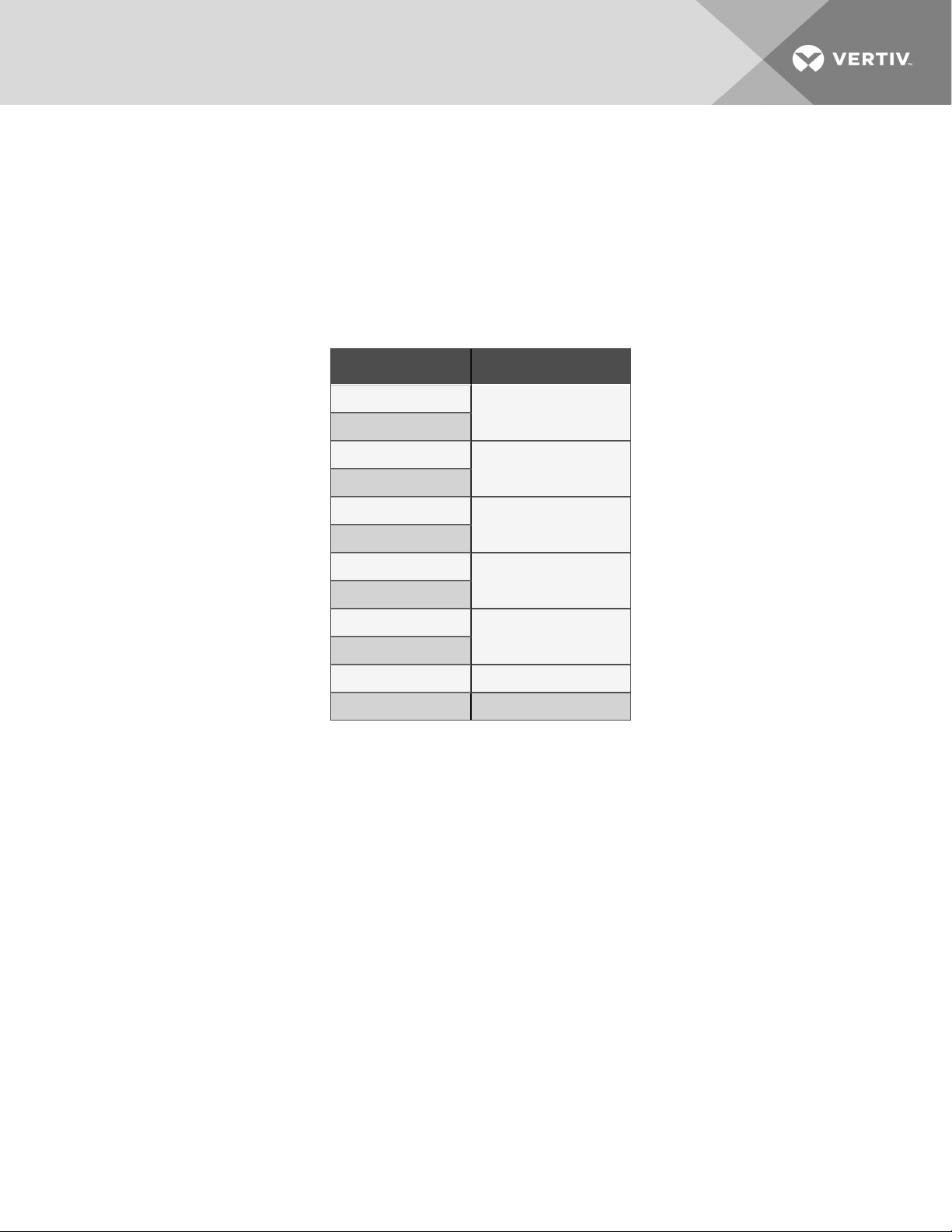
Table 1.1 UPS Models and Power Ratings
MODEL NUMBER NOMINAL POWER RATING
GXT5-750IRT2UXL
GXT5-750IRT2UXLE
GXT5-1000IRT2U XL
GXT5-1000IRT2U XLE
GXT5-1500IRT2UXL
GXT5-1500IRT2UXLE
GXT5-2000IRT2UXL
GXT5-2000IRT2UXLE
GXT5-3000IRT2UXL
GXT5-3000IRT2UXLE
GXT5-3KL620RT2UXL 3000 VA/2700 W
GXT5-3KL630RT2UXL 3000 VA/3000 W
750 VA/750 W
1000 VA/1000 W
1500 VA/1500 W
2000 VA/2000 W
3000 VA/3000 W
1 GXT5 Description
3
Page 8
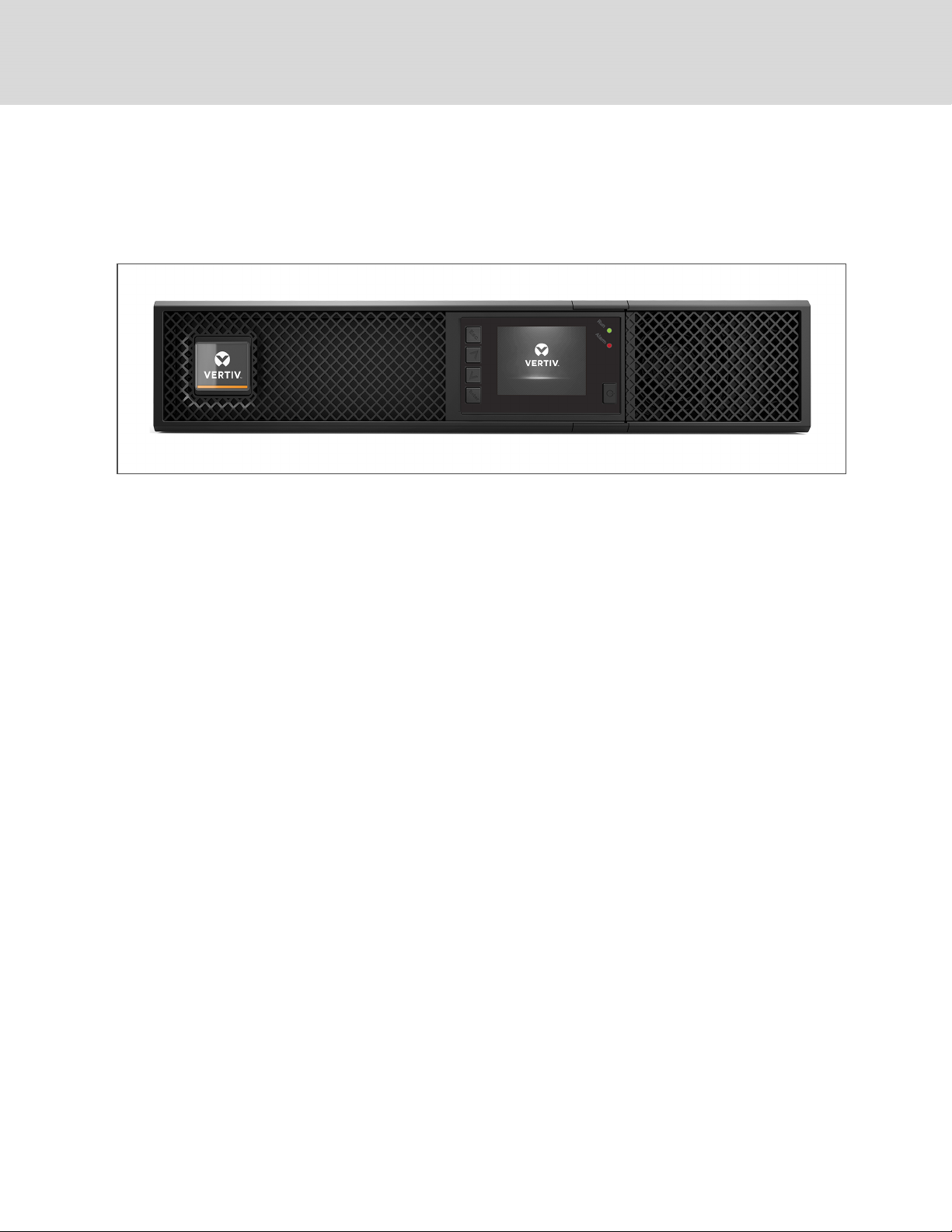
1.2 Front Panels
The various GXT5 models have the same general appearance, with the main difference being the
receptacle types on the rear panel.
Figure 1.1 Front View
4
Vertiv | Liebert® GXT5™ Installer/UserGuide
Page 9
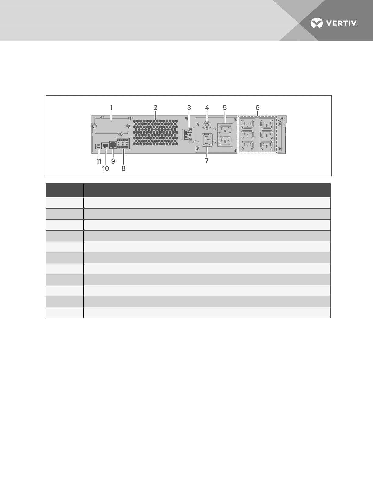
1.3 Rear Panels
The following figures detail the rear-panel features for each GXT5 model.
Figure 1.2 GXT5-750/1000IRT2UXL (XLE) Rear Panel
ITEM DESCRIPTION
1 Liebert® IntelliSlot™ port
2 Ventilation Hole
3 External-battery-cabinet connector
4 Input c ircuit-breaker reset button, 10-A
5 Non-programmable C13 output receptacles
6 Programmable C13 output receptacles
7 C14 input-power plugand cable
8 Terminal-block/Dry-contact communication connectors
9 RS-232 port
10 RS-485 port
11 USB port
1 GXT5 Description
5
Page 10
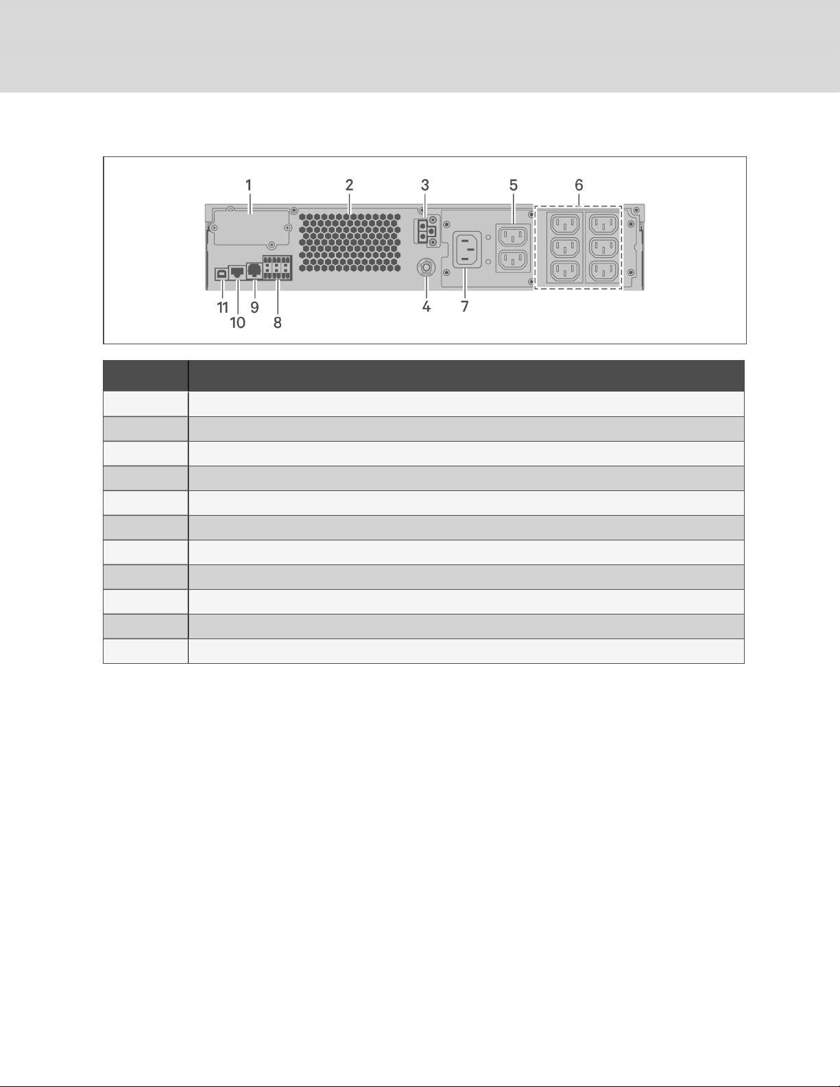
Figure 1.3 GXT5-1500IRT2UXL (XLE) Rear Panel
ITEM DESCRIPTION
1 Liebert® IntelliSlot™ port
2 Ventilation Hole
3 External-battery-cabinet connector
4 Input c ircuit-breaker reset button, 10-A
5 Non-programmable C13 output receptacles
6 Programmable C13 output receptacles
7 C14 input-power plugand cable
8 Terminal-block/Dry-contact communication connectors
9 RS-232 port
10 RS-485 port
11 USB port
6
Vertiv | Liebert® GXT5™ Installer/UserGuide
Page 11
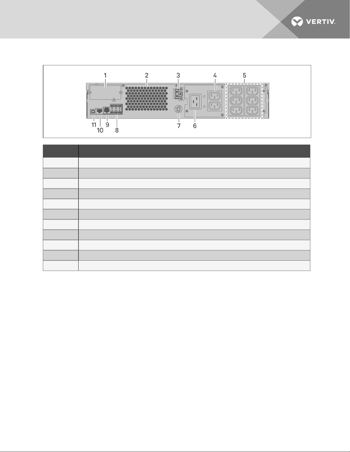
Figure 1.4 GXT5-2000IRT2UXL (XLE) Rear Panel
ITEM DESCRIPTION
1 Liebert® IntelliSlot™ port
2 Ventilation Hole
3 External-battery-cabinet connector
4 Non-programmable C13 output receptacles
5 Programmable C13 output receptacles
6 C20 input-power plug and cable
7 Input circuit-breaker reset button, 16-A
8 Terminal-block/Dry-contact communication connectors
9 RS-232 port
10 RS-485 port
11 USB port
1 GXT5 Description
7
Page 12
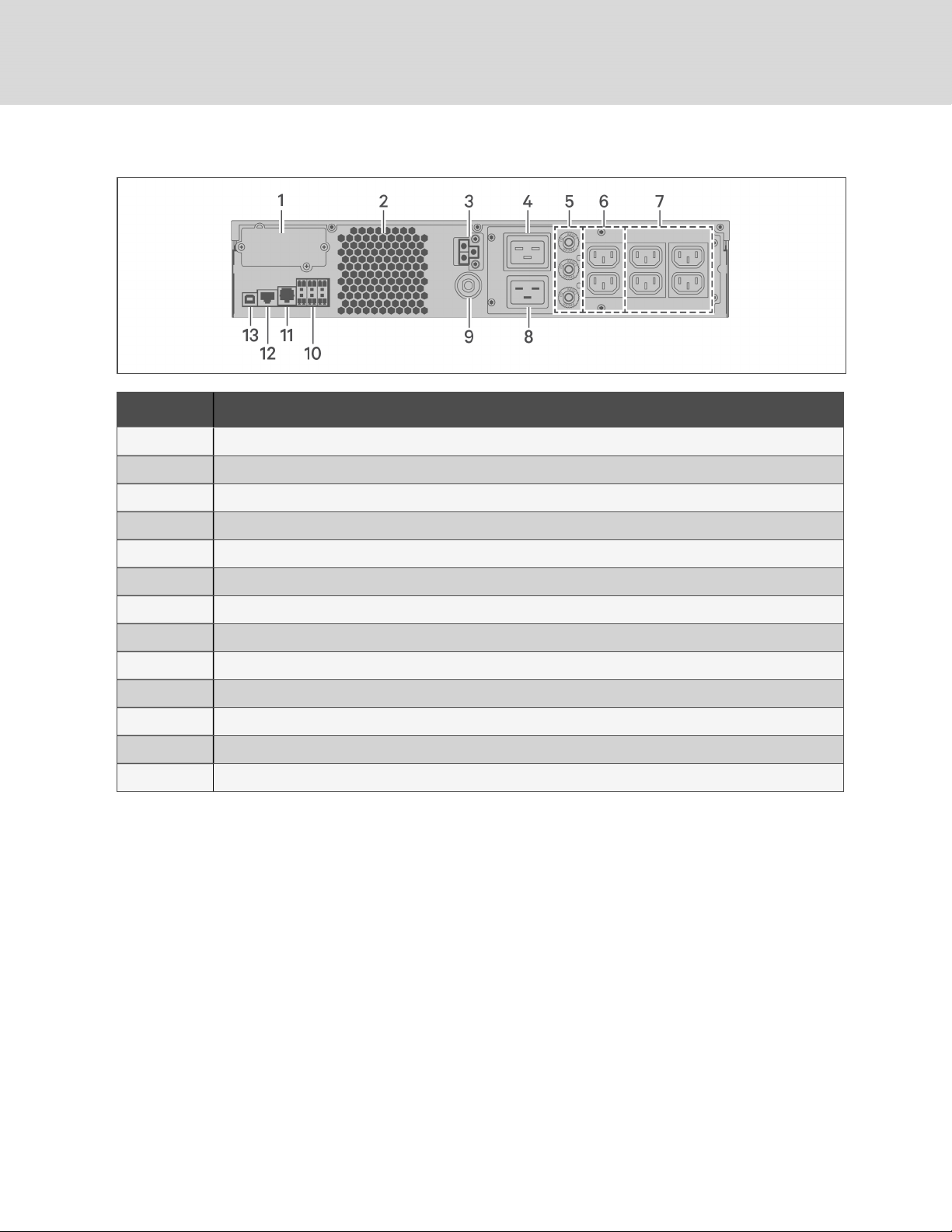
Figure 1.5 GXT5-3000IRT2UXL (XLE) Rear Panel
ITEM DESCRIPTION
1 Liebert® IntelliSlot™ port
2 Ventilation Hole
3 External-battery-cabinet connector
4 Non-programmable C19output receptacle
5 Output circuit-breaker reset buttons, 10-A
6 Non-programmable C13 output receptacles
7 Programmable C13 output receptacles
8 C20 Input-power plug and cable
9 Input circuit-breaker reset button, 20-A
10 Terminal-block/Dry-contact communication connectors
11 RS-232 port
12 RS-485 port
13 USB port
8
Vertiv | Liebert® GXT5™ Installer/UserGuide
Page 13
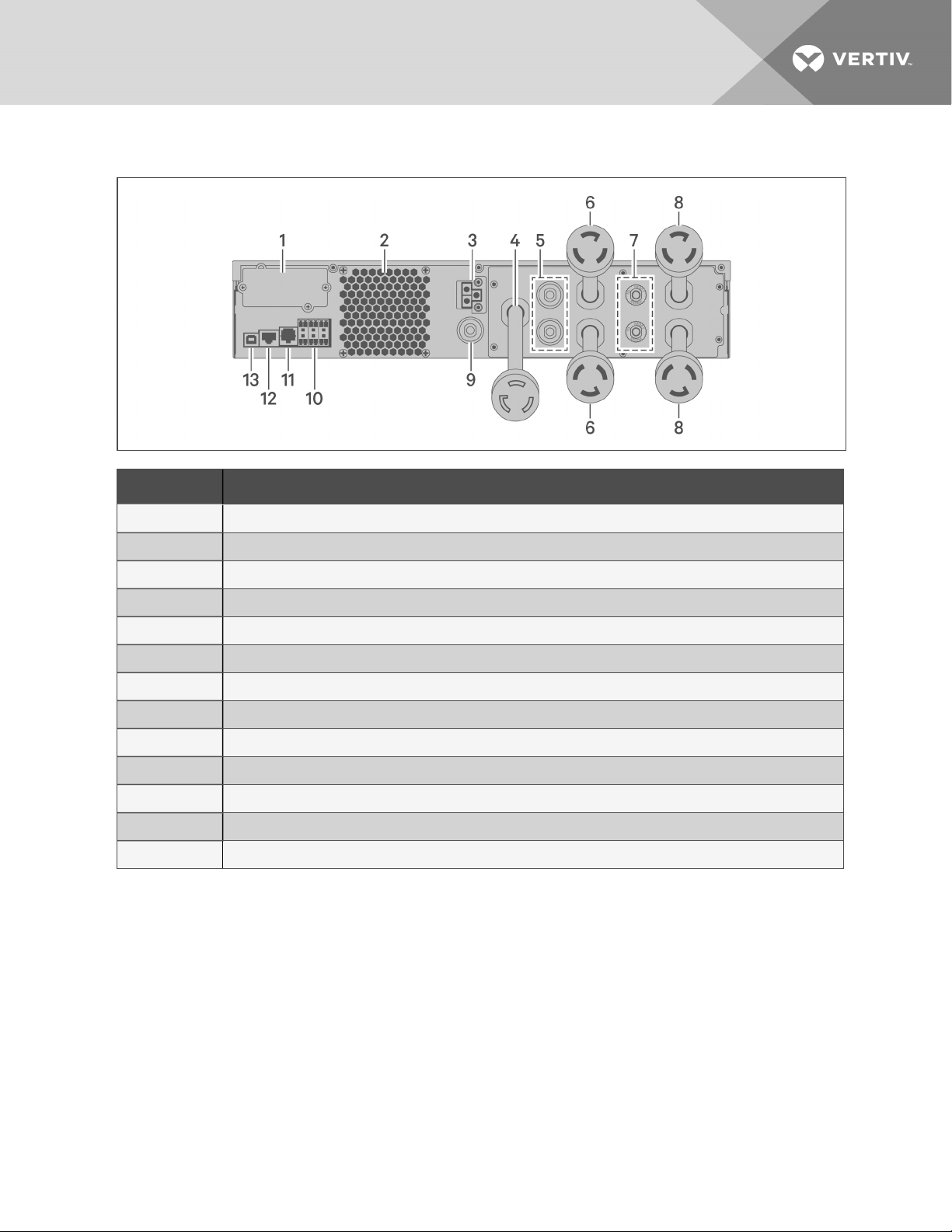
Figure 1.6 GXT5-3KL620RT2UXL Rear Panel
ITEM DESCRIPTION
1 Liebert® IntelliSlot™ port
2 Ventilation Hole
3 External-battery-cabinet connector
4 Input pow er cable, L6-20P
5 Output circuit-breaker reset buttons, 20-A
6 Output cable, L6-20R
7 Output circuit-breaker reset buttons, 15-A
8 Output cables, L6-15R
9 Input circuit-breaker reset button
10 Terminal-block/Dry-contact communication ports
11 RS-232 port
12 RS-485 port
13 USB port
1 GXT5 Description
9
Page 14
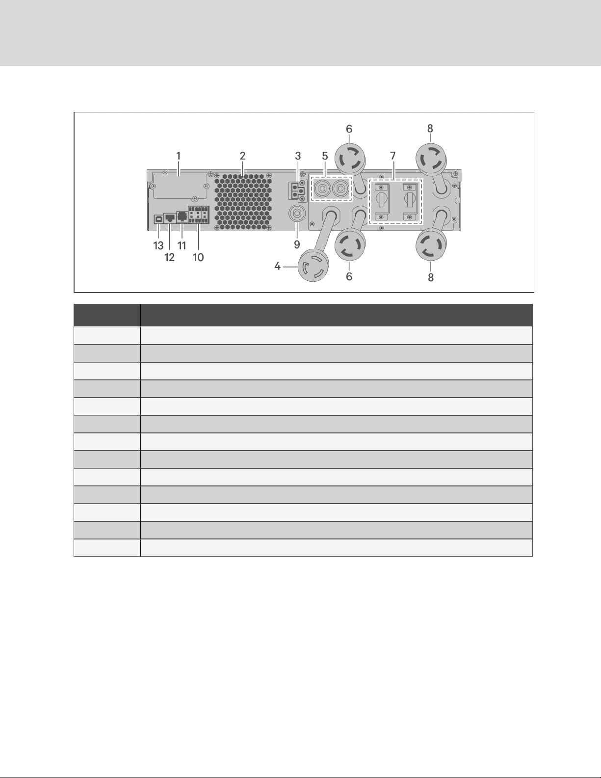
Figure 1.7 GXT5-3KL630RT2UXL Rear Panel
ITEM DESCRIPTION
1 Liebert® IntelliSlot™ port
2 Ventilation Hole
3 External-battery-cabinet connector
4 Input pow er cable, L6-30P
5 Output circuit-breaker reset buttons, 20-A
6 Output cable, L6-30R
7 Output circuit breakers, 15-A
8 Output cables, L6-15R
9 Input circuit-breaker reset button
10 Terminal-block/Dry-contact communication ports
11 RS-232 port
12 RS-485 port
13 USB port
10
Vertiv | Liebert® GXT5™ Installer/UserGuide
Page 15
1.4 Battery Cabinet
Optional battery cabinets are available for the UPS, and include a single battery-connector cable. Up to 10
battery cabinets may be connected in parallel to the UPS, and up to 6 can be detected using EBCdetection. See Table 7.4 on page63, for the cabinet specifications. For approximate battery run times
with additional EBCs, see Battery Run Times on page63. See Installing External Battery Cabinets on
page16, to connect the cabinets.
Figure 1.8 Battery Cabinet
ITEM. DESCRIPTION
1 Battery connectors
2 Isolation breaker
1.5 Major Internal Components and Operating Principle
Figure 1.9 on the next page, shows the UPSoperating principle. Table 1.2 on the next page, describes
the function of the major components in the UPS.
NOTE: Figure 1.9 on the next page, is one example of basic operation.
1 GXT5 Description
11
Page 16
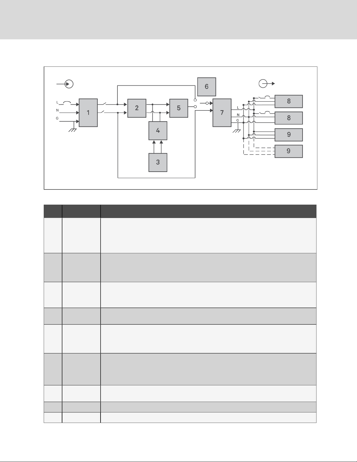
Figure 1.9 Basic Operating Principle Diagram
Table 1.2 Major Components
ITEM COMPONENT OPERATION/FUNCTION
Transient
Voltage Surge
1
Suppression
(TVSS)and
EMI/RFI Filters
Provide surge protection. Filter electromagnetic interference (EMI) and radio frequency interference
(RFI). Minimize surges or interferenc e present in the utility power andprotect devices connected on the
same branch as the UPS.
Rectifier/Power
2
3 Batteries
4
5 Inverter
6
7 EMI/RFI Filters
8 Outlet group Programmable output receptacles.
9 Outlet group Generaloutput receptacles.
Factor
Correction
(PFC) Circuit
DC-to-DC
Converter
Dynamic
Internal Bypass
In normaloperation, converts utilityAC power to regulated DC power for use by the inverter while
ensuring that the wave shape of the input current used by the UPS is near ideal. Extracting thissine-wave
input current ensures efficient use of utility power and reduces reflected harmonic distortion making
cleaner power available to devices that are not protected bythe UPS.
Valve-regulated, non-spillable, lead-acid batteries.
NOTE: To maintain battery design life, operate the UPS in an ambient temperature of 59°F to 77°F
(15°C to 25°C).
Raises the DC voltage from the battery to the optimum operating voltage for the inverter. This allows the
inverter to operate continuouslyat its optimum efficiency and voltage, thus increasing reliability.
In normaloperation, inverts the DC output of the PFC circuit into precise, regulated sine-wave AC power.
When utility power fails, the inverter receives DC power from the DC-to-DC converter. In either
operating mode, the UPS inverter remains on-line, generating clean, precise, regulated AC-output
power.
In the unlikely event of UPS failure suc h asoverload or over-temperature, automaticallytransfers the
connected load to bypass.
To manually transfer the connected load from inverter to bypass, see Transferring from Normalto
Bypass Mode on page26.
Filter electromagnetic interference (EMI) and radio frequency interference (RFI). Minimize interference
present in the utility power andprotect devices connected on the same branch asthe UPS.
12
Vertiv | Liebert® GXT5™ Installer/UserGuide
Page 17

1.6 UPS States and Operating Modes
NOTE: See LED Indicators on page31, for description of the run-indicator and alarm-indicator LEDs
mentioned in this section.
1.6.1 Normal Mode
When utility power is normal, Normal mode employs the rectifier and inverter to provide voltage- and
frequency-stabilized power to the load. The charger charges the battery in normal mode. On the frontpanel display, the run-indicator (green)is On, the alarm indicator is OFF, and the buzzer is silent.
1.6.2 Bypass Mode
Bypass mode supplies power to the load from the bypass source (utility power) if an overload or fault
occurs during normal operation. On the front-panel display, the run indicator (green) is On, the alarm
indicator (yellow)is On, and the buzzer beeps once each seconds. The LCD "Current" screen displays "On
Bypass."
NOTE: If utility power fails or if the utility voltage goes outside of the permissible range during bypassmode operation, the UPS shuts down and no output is supplied to the load.
1.6.3 Battery Mode
Battery mode supplies battery power to the load if utility power fails or if the utility voltage goes outside of
the permissible range. On the front-panel display, the run indicator (green) is On, the alarm indicator
(yellow)is On, and the buzzer beeps once each second. The LCD "Current" screen displays "On Battery."
NOTE: The batteries are fully-charged before shipment. However, transportation and storage
inevitably cause some loss of capacity. To ensure adequate back-up time, charge the batteries for atleast 8 hours before first start-up.
NOTE: If utility power fails and the batteries are charged, you may cold-start the UPS in battery mode
and use battery power to extend system availability for a time.
NOTE: Powering-off the UPS when it is in battery mode results in loss of output power to the
connected load.
1.6.4 Frequency Converter Mode
All models of the GXT5 are capable of frequency conversion. Frequency Conversion Mode can be selected
using the configuration program. Allowable frequency operating modes include:
• Auto Sensing - 50 Hz or 60Hz – Bypass Enabled
• Auto Sensing - 50 Hz or 60Hz – Bypass Disabled
• Frequency Converter - 50 Hz – Bypass Disabled
• Frequency Converter - 60Hz – Bypass Disabled
NOTE: The default for all models of the Liebert® GXT5 is “Auto Sensing - 50 Hz or 60Hz – Bypass
Enabled.”
1 GXT5 Description
13
Page 18

1.6.5 ECO Mode
The energy-saving ECO mode reduces power consumption by powering the load via bypass if the bypass
voltage is normal or by powering the load via the inverter when the bypass voltage is abnormal. You can
use ECOmode to power equipment that is not sensitive to power-grid quality to via bypass and reduce
power consumption.
NOTE: During Eco mode, if a bypass-failure or abnormal-bypass-voltage notification appears when the
output is not overloaded, the UPS will transfer to Normal Mode. However, if a notification showing
bypass failure or abnormal bypass voltage appears when the output is overloaded, the UPS will shut
down the bypass.
14
Vertiv | Liebert® GXT5™ Installer/UserGuide
Page 19

2 INSTALLATION
Do not start the UPS until after the installation is finished.
WARNING! Risk of electrical shock. Can cause equipment damage, injury and death. Before
beginning installation, verify that all external overcurrent protection devices are open (Off), and
that they are locked-out and tagged appropriately to prevent activation during the installation,
verify with a voltmeter that power is Off and wear appropriate, OSHA-approved personal
protective equipment (PPE) per NFPA 70E. Failure to comply can cause serious injury or death.
Before proceeding with installation, read all instructions. Follow all local codes.
2.1 Unpacking and Inspection
Unpack the UPS and conduct the following checks:
• Inspect the UPS for shipping damage. If any shipping damage is found, report it to the carrier
and your local Vertiv representative immediately.
• Check the accessories included against the packing list. If there is any discrepancy, contact
your local Vertiv representative immediately.
CAUTION: The UPS is heavy (see Specifications on page57, for the weight). Take proper
precautions when lifting or moving the unit.
2.2 Pre-installation Preparation
• Install the UPS indoors in a controlled environment, where it cannot be accidentally turned Off.
The installation environment should meet the specifications listed in Specifications on page57.
• Place the UPS in an area of unrestricted air-flow around the unit, away from water, flammable
liquids, gases, corrosives, and conductive contaminants. Avoid direct sunlight
NOTE: Operating the UPS in temperatures above 77°F (25°C) reduces battery life.
2.2.1 Installation Clearances
Maintain at least 4in.(100mm) clearance in the front and rear of the UPS. Do not obstruct the air inlets on
the front panel and rear panel of the UPS. Blocking the air inlets reduces ventilation and heat dissipation,
shortening the service life of the unit.
2.3 Installing the UPS
The UPS may be installed as a tower or in a rack, depending on available space and use considerations.
Determine the type of installation and follow the appropriate instructions. See Tower Installation on the
next page or Rack Installation on the next page.
NOTE: When installing the UPS or making input and output connections, comply with all relevant
safety codes and standards
2 Installation
15
Page 20
2.3.1 Tower Installation
To install the UPS as a tower:
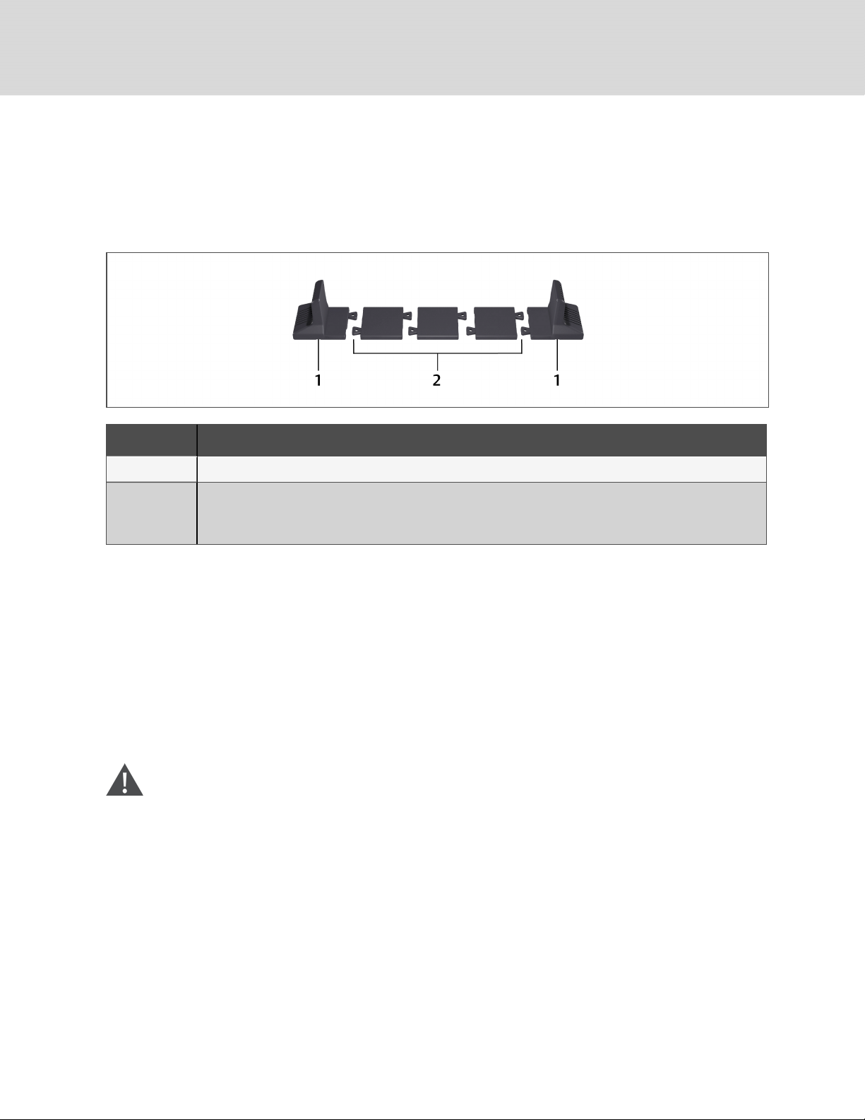
1. Take the support bases out of the accessories box.
Figure 2.1 Support bases
NO. DESCRIPTION
1 Support bases
Spacers with c onnec tors
2
NOTE: Three spacers are shown here. However, the number of spacers varies depending on your UPS
model and the number of battery cabinets in your system.
2. If optional, Liebert® external battery cabinets will be connected, take out the spacers shipped
with the battery cabinet.
3. Connect the spacers and the support bases as shown in Figure 2.1 above. Each GXT5 requires
2support bases, one in the front and one in the rear.
4. Place the GXT5 and any battery cabinets on the 2support bases.
2.3.2 Rack Installation
When installed in a rack enclosure, the GXT5 UPS and external battery cabinets (EBC) must be supported
by a shelf or rack-mount rails. Because different rack-mount options install differently, refer to the
installation instructions provided with the rack-mount kit.
CAUTION: The GXT5 is heavy. The UPS must be installed as near the bottom of a rack as
possible. If placed too high, it can make the rack top-heavy and prone to tipping over. For unit
weights, see Specifications on page57.
2.4 Installing External Battery Cabinets
Optional, external battery cabinets (EBC) may be connected in parallel to the UPS to provide additional
battery run time. For approximate battery run times with additional EBCs, see Battery Run Times on
page63.
External battery cabinets are placed on one side of the UPS in a tower configuration or stacked beneath
the UPS in a rack configuration. Up to 10 EBCs may be connected to the UPS, and up to 6 may be
detected using EBC-detection.
16
Vertiv | Liebert® GXT5™ Installer/UserGuide
Page 21

WARNING! Risk of electric shock. Can cause injury or death. Disconnect all local and remote
electric power supplies before working with the UPS. Ensure that the unit is shut down and
power has been disconnected before beginning any maintenance.
CAUTION: The external battery cabinet(s) are heavy, see Table 7.4 on page63. Take proper
precautions when lifting them.
To install the EBC(s):
1. Inspect the EBC for freight damage. Report damage to the carrier and your local dealer or
Vertiv representative.
2. For tower installation:
• An additional set of support-base extensions ships with each EBC.
• See the steps in Tower Installation on the previous page, to connect the support
extenders and install the bases.
– or –
For rack installation:
• Rack-mount hardware ships with the EBC.
• Refer to the instructions included with the rack-mount kit to install.
NOTE: Optional slide rails and securing hardware are sold separately. Please contact your Vertiv
representative for options and Vertiv Technical Support for assistance.
3. Verify that the EBC breaker is in the "Off" position.
4. Connect the supplied EBC cable(s) to the rear of the cabinet, then to the rear of the UPS, see
Figure 2.2 on the next page.
5. Turn the EBC breaker to the "On" position.
6. Verify the circuit breaker on the EBC is in the "On" position.
The additional back-up run time is enabled.
NOTE: When removing an EBC, turn off the circuit breaker on the rear of the cabinet before
disconnecting the cable.
NOTE: If shipping or storing the UPS for an extended time, disconnect the EBC(s) minimize stand-by
current drain on the batteries and help maintain design life.
2 Installation
17
Page 22
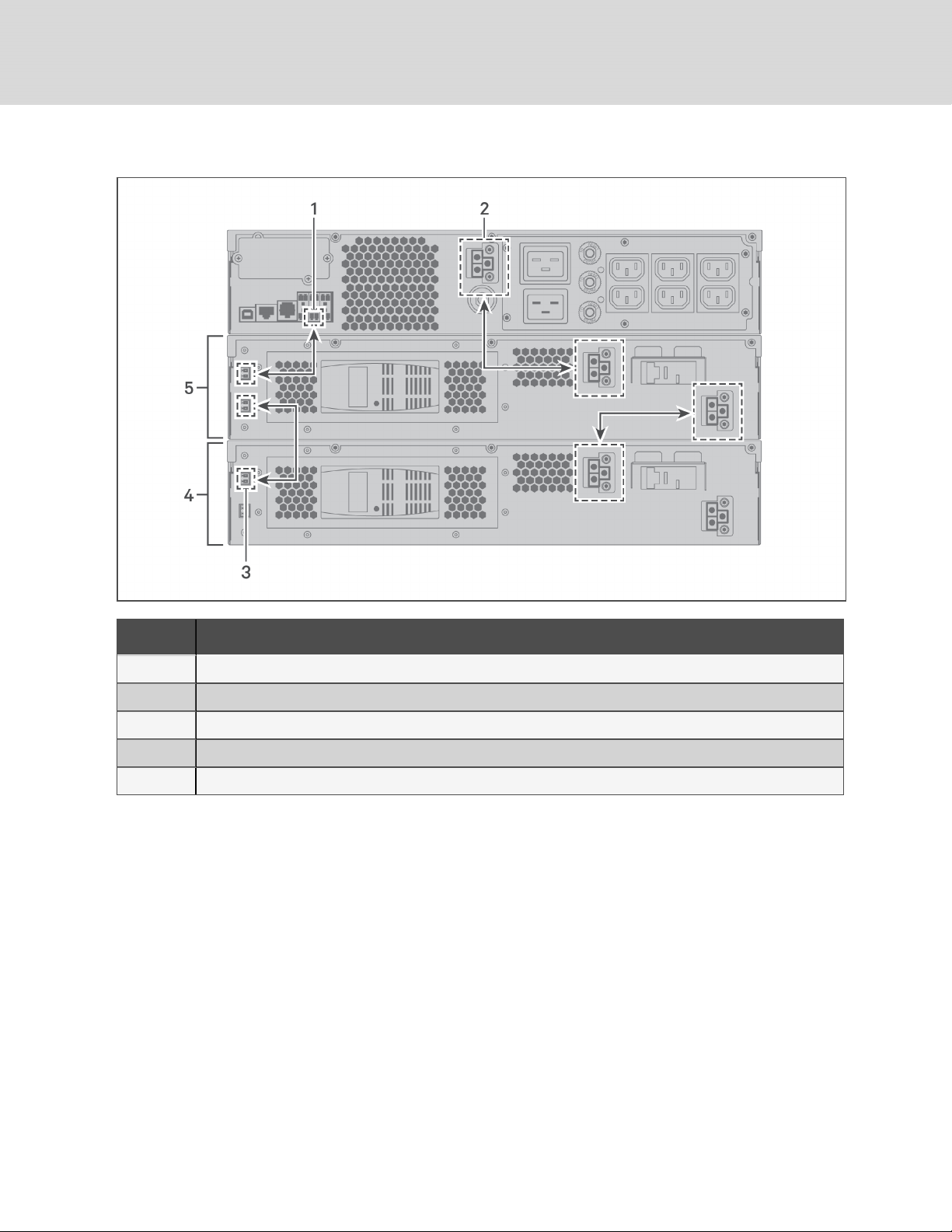
Figure 2.2 EBCs connected to the UPS
ITEM DESC RIPTION
1 EBC-detection dry-contact port (See Table 2.2 on page22, for details.)
2 EBC connector
3 EBC-detection port
4 External battery cabinet
5 Externalbattery cabinet
18
Vertiv | Liebert® GXT5™ Installer/UserGuide
Page 23
2.5 Connecting AC Input Power
Ensure that all the loads are turned Off. Prepare an input power supply that is properly protected by a
circuit breaker in accordance with national and local electrical codes. The wall receptacle must be
grounded. We recommend installing an upstream circuit breaker of the same series as the input circuit
breaker of the GXT5.
Table 2.1 below, lists the specifications of the input circuit breaker on the rear panel by UPS model
Table 2.1 Input circuit breaker
specifications
MODEL RATED CIRCUIT BREAKER
GXT5-750IRT2UXL
GXT5-750IRT2UXLE
GXT5-1000IRT2U XL
GXT5-1000IRT2U XLE
GXT5-1500IRT2UXL
GXT5-1500IRT2UXLE
GXT5-2000IRT2UXL
GXT5-2000IRT2UXLE
GXT5-3000IRT2UXL
GXT5-3000IRT2UXLE
GXT5-3KL620RT2UXL 20 A
GXT5-3KL630RT2UXL 20 A
10 A
10 A
10 A
16 A
20 A
To connect AC-input power, plug the input plug of the UPS into the input-power connection.
NOTE: If the input plug will serve as the disconnecting device, the wall socket/outlet must be near the
UPS and must be easily accessible, per the National Electric Code/NFPA 70 requirements.
2.6 Connecting Loads
2 Installation
750-Va to 2000-VA models have three groups of outlets:
• One group is not controlled (always On).
• Two groups are controlled with programmed responses or an SNMP network.
3000-A models have four groups of outlets:
• Two groups are not controlled (always On).
• Two groups are controlled with programmed responses or an SNMP network.
NOTE: When connecting load, verify that the equipment is plugged into the appropriate outlets if any
of the outlets will be controlled.
NOTE: Do not overload any output receptacle. Output cable length should not exceed 10m (32.8ft).
19
Page 24

To connect equipment:
1. Plug equipment into the appropriate output receptacles on the rear of the UPS, see the
appropriate figure for your model in Rear Panels on page5.
2. Install the cable-strain-relief fixtures, see Figure 2.3 below, to prevent accidental
disconnection of the input and output cables:
a. Insert the attachment end into the hole provided on the rear of the unit.
b. Place the cable(s) to secure in the loop, and tighten the loop around the cable(s).
Figure 2.3 Cable Strain-relief Fixture
20
ITEM DESCRIPTION
1 Power-cord loop
2 Fixture-attachment end
2.7 Communication Connections
The UPS offers several communication interfaces and ports.
NOTE: We recommend that signal-cable lengths be less than 10ft(3m), and are kept away from power
cabling.
2.7.1 Connecting IntelliSlot Communication
The IntelliSlot ports accepts two optional cards:
The Liebert® IntelliSlot™ Relay card (IS-RELAY) card provides dry-contact relay output for custom-wired
applications.
The Liebert® IntelliSlot™ Unity card (RDU101) provides SNMP monitoring of the UPS across the network
and/or building management system and lets you monitor external temperature, humidity and contactclosure inputs using external sensors.
Vertiv | Liebert® GXT5™ Installer/UserGuide
Page 25

See the appropriate figure for your model in Rear Panels on page5, for the location of the card port.
To install an IntelliSlot Card:
1. Remove the screws from the slot cover plate and remove the plate.
2. Insert the card into the slot, and secure with the screws that held the cover plate.
To make connections to the card, refer to the Installer/User Guide for the appropriate IntelliSlot card
available at www.Vertiv.com.
2.7.2 Connecting to the Dry-contact Port
The UPS includes a dry-contact port. See the appropriate figure for your model in Rear Panels on page5,
for the location of the port. Figure 2.4 below, shows the ports and Table 2.2 on the next page, describes
each port.
The I/O dry contact port capacity is 125Vdc, 0.5A; 30Vdc, 1A
Figure 2.4 Dry-contact Port and Pin Layout
2 Installation
NOTE: Pins 7 and 8 are shorted before delivery.
NOTE: The emergency power-off (EPO) action of the UPS closes the rectifier, inverter and static
bypass, but it cannot disconnect the UPS mains input inside. To completely disconnect the UPS,
disconnect the upstream input circuit breaker when generating the EPO. For details on
REPOconnection and operation, see Connecting a Remote Emergency Power-off (REPO) Switch on
the next page.
21
Page 26

Table 2.2 Dry-contact Connection and Pin-out Descriptions
PORT
NO.
1 Input 1
2 Input 2
3
REPO
PORT
NAME
Battery
Detection
REPO
Input
PIN
PIN NAME DESCRIPTION
NO.
Disable/Battery mode
shutdown/Any mode
1
shutdown (Remote Comms
Shutdown)
2 Signal Ground Signal Ground
Disable/Battery mode
shutdown/Any mode
3
shutdown (Remote Comms
Shutdown)
4 Signal Ground Signal Ground
5 EBC Detection
6 EBC Detection
7 +5V REPO power supply, 5-Vdc 100-mA
8 REPO Coil -NC
Default: Disable, can be set via the LCD settings page. User can choose
dry contact as NO/NC. when NO, Pin 1 and Pin2 are shorted, the
function is active. when NC, Pin1 and Pin2 are open, the function is
active.
Default: Disable, can be set via the LCD settings page. User can choose
dry contact as NO/NC. when NO, Pin 1 and Pin2 are shorted, the
function is active. when NC, Pin1 and Pin2 are open, the function is
active.
Default: Normally-Open (NO), automatically detects number of externalbattery cabinets when pins5 and6 are connected to the detection port,
see Installing External Battery Cabinets on page16.
Default: Normally-Open (NO), automatically detects number of externalbattery cabinets when pins5 and6 are connected to the detection port,
see Installing External Battery Cabinets on page16.
NC, activated when Pin 7 and Pin 8is open
NOTE: For details on REPOconnection and operation, see
Connecting a Remote Emergency Power-off (REPO) Switch below.
5 Output 5
6 Output 6
Low Battery/Onbattery/
9
Onbypass/UPSfault
10 Signal Ground Signal Ground
Low Battery/Onbattery/
11
Onbypass/UPSfault
12 SignalGround SignalGround
Default: Low battery, can be set viathe LCD settings page. When the
system has afault, short Pin 9 andPin 10
Default: UPS fault, can be set viathe LCD settings page. When the
system has afault, short Pin 11 andPin 12
2.7.3 Connecting a Remote Emergency Power-off (REPO) Switch
The UPS includes an EPO connection in the dry-contact port. See the appropriate figure for your model in
Rear Panels on page5, for the location of the port.
UPS ships with a REPO jumper installed, allowing the UPS to operate as a normally-closed switch system
(fail-safe). Opening the circuit disables the UPS. To connect a REPOswitch that opens the circuit to shut
down the rectifier and inverter and power-off the UPS, use a cable from the remote switch to plug into the
REPO-port on the UPS.
In normal conditions, the REPO switch cannot cut off the UPS input power. When the REPO switch trips,
the UPS generates an alarm and immediately cuts-off output power. When the emergency condition is
resolved, the UPS will not return to normal operation until you reset the REPO switch and manually poweron the UPS.
22
Vertiv | Liebert® GXT5™ Installer/UserGuide
Page 27

To make the cable for the REPO connection:
Figure 2.5 below, shows the cable required to make the connection. We recommend using 18AWG to
22AWG (0.82mm2to 0.33mm2) copper-core cable.
1. Remove the insulation from the end of two cables.
2. Insert the stripped end into the plug terminals 1 and 2 respectively, then press down the
terminals. Make sure that the cables are secure in the plug to prevent failure because of loose
contact.
To connect a UPS to the REPO switch
CAUTION: To maintain safety (SELV) barriers and electromagnetic compatibility, signal cables
should be shielded and run separately from power cables.
1. Connect one end of the cable to the remote switch, see Figure 2.5 below.
2. Remove the factory-installed jumper from pins 7 and 8 of the dry-contact port on the UPS
3. Connect the plug to pins 7 and 8.
Figure 2.5 Cable/Plug for Connecting REPOswitch to UPS REPO port
ITEM DESCRIPTION
1 Terminal 1
2 Terminal 2
3 Plug (connects to REPO port on UPS)
4 REPO switch
2.7.4 Connecting a USB Cable
The UPS includes a USB connector. See the appropriate figure for your model in Rear Panels on page5,
for the location of the port.
The standard, B-type USB port connects the UPS to a network server or other computer system.
The USB port supports HID/CDC protocol. The CDC protocol is reserved for service software.
2 Installation
23
Page 28

2.7.5 Connecting Sensors to the Control Port
The UPS supports the Vertiv temperature and temperature/humidity sensors. The RJ-45 port is used for
sensor connection. See the appropriate figure for your model in Rear Panels on page5, for the location of
the port.
When connected, the sensor address must be 1to20.
The GXT5 supports two sensors:
• Liebert® IRM-S01T
• Liebert® IRM-S02TH
24
Vertiv | Liebert® GXT5™ Installer/UserGuide
Page 29

3 OPERATING THE UPS
WARNING! Risk of electric shock. Can cause injury or death. Hazardous mains and/or battery
voltage exists behind the protective cover No user accessible parts are located behind the
protective covers that require a tool for removal. Only qualified service personnel are
authorized to remove such covers. If maintenance for rack is needed, notice that the neutral
line is live.
3.1 Silencingthe Audible Alarm
The audible alarm may sound during UPS operation. To silence the alarm, press and hold the ESC button
for 2seconds. The button is located on the front-panel display, see Operation and Display Panel on
page29.
3.2 Starting-up the UPS
IMPORTANT! Do not start the UPS until after the installation is finished, the system is commissioned
by an authorized engineer, and the external input circuit breakers are closed.
CAUTION: Starting the UPS applies mains/utility power to the output terminals. Make sure that
the load power is safe and ready to accept power. If the load is not ready, isolate the load with
the output terminal.
The UPS starts in Normal Mode.
To start the UPS:
1. Ensure that the REPO connector on the rear of the unit has a jumper between pins 7-8 or that
it is properly wired to an Emergency Power- Off circuit (normally closed).
2. Make sure the breaker supplying power to the UPS is closed, and if necessary press the input
circuit breaker reset buttons at the rear of the UPS.
3. Close all output breakers on the rear of the UPS (or in an external panel board, if used).
4. Power-on the UPS by pressing and holding the power button on the operation and display
panel until the confirmation dialog appears. Use the Up/ Down arrows to select YES, then press
Enter.
5. If this is the first-time start-up of the UPS, the Start-up Guidance wizard opens to set the basic
parameters of the UPS. Follow the prompts.
For detailed description of UPS display functions and settings, see Operation and Display Panel
on page29.
3.3 Transferring to Battery Mode
The UPS operates in Normal mode unless the mains/utility power fails or it is performing a battery self test,
then it automatically transfers to Battery mode for the back-up time available or the mains/utility power is
restored. Once input power is restored, the UPS returns to Normal mode.
NOTE: Battery back-up run times are listed in Battery Run Times on page63.
3 Operating the UPS
25
Page 30

3.4 Transferring from Normal to Bypass Mode
Press and hold the power button for 2 seconds.
• If the bypass power is within normal operating range, the option to continue to Bypass mode or
turn-off the UPS displays:
a. Use the arrow buttons to select To the Bypass, and press Enter.
b. Use the arrow buttons to select No or Yes, then press Enter to confirm.
• If the bypass power is outside normal operating range, do not transfer to Bypass mode.
3.5 Transferring from Bypass to Normal Mode
Press and hold the power button for 2 seconds.
• If the UPS is operating normally, without faults, the option to continue to turn-on or turn-off the
UPS displays:
a. Use the arrow buttons to select Turn on UPS, and press Enter.
b. Use the arrow buttons to select No or Yes, then press Enter to confirm.
NOTE: The UPS automatically switches back to normal mode after an "overheated" or "overloaded"
fault is cleared and normal power is restored.
3.6 Shutting-down the UPS Completely
WARNING! Risk of electric shock. Can cause injury or death. Disconnect all local and remote
electric power supplies before working with the UPS. Ensure that the unit is shut down and
power has been disconnected before beginning any maintenance.
Transfer to Bypass mode, see Transferring from Normal to Bypass Mode above. Then, if power to the load
is not needed, open the main-input circuit breaker.
3.7 Remote Emergency Power-off (REPO)
REPO turns off the UPS in emergency conditions such as fire or flood. When an emergency occurs, the
REPO switch turns off the rectifier and inverter and stops powering the load immediately. The battery
stops charging and discharging.
To manually power-off in an emergency, disconnect the terminal connecting the REPO port on the rear of
the UPS.
If mains/utility power is present, the UPS control circuit remains active even though output power is
disabled. To remove all mains/utility power, disconnect the external main-input MCB.
3.8 Auto and Manually Restarting
During an input-power failure, the UPS draws power from the battery to supply the load until depleted,
then the UPS shuts down. The UPS automatically restarts and recovers output power to the load when:
• Mains/Utility power is restored
• The UPS Auto Restart function is enabled.
26
Vertiv | Liebert® GXT5™ Installer/UserGuide
Page 31

NOTE: A restart delay of 0 seconds for single UPS and 10 seconds for parallel systems is set by default.
You can enable/disable auto restart and adjust the delay parameters, see Editing Display and Operation
Settings on page47.
To manually restart the UPS, press the power button, see Starting-up the UPS on page25.
3 Operating the UPS
27
Page 32

This page intentionally left blank
28
Vertiv | Liebert® GXT5™ Installer/UserGuide
Page 33

4 OPERATION AND DISPLAY PANEL
NOTE: The UPS has a gravity-sensor function that automatically rotates the LCD display depending on
tower or rack installation. See Display orientation on page38.
The operation/display panel includes LED indicators, function keys, and an LCDinterface to configure
and control UPS operation.
Figure 4.1 UPS Front-panel Display
ITEM DESCRIPTION
1 Run indicator LED, see LED Indicators on page31.
2 Alarm indicator LED, see LED Indicators on page31.
3 Power button, see Table 4.1 on the next page.
4 Menu keys, see Table 4.1 on the next page.
5 LCD panel.
4 Operation and Display Panel
29
Page 34

Table 4.1 Display-panel Button Functions and Descriptions
BUTTON FUNCTION DES CRIPTION
Enter Confirm or enter selection.
Up Move to previous page, increase value, move left.
Down Move to next page, decrease value, move right.
Escape Go back.
Power Power-on the UPS, power-off the UPS, transfer to Bypass Mode.
NOTE: While the UPS is operating, the LCD will dim and display a screen saver if there is no active alarm
or user interaction for two minutes, see Figure 4.2 below. If an alarm or fault occurs or if any button is
pressed, the UPS-flow screen displays.
Figure 4.2 LCD Screen Saver
30
Vertiv | Liebert® GXT5™ Installer/UserGuide
Page 35

4.1 LED Indicators
The LEDs on the front-panel display indicate operation and alarm statuses of the UPS.
NOTE: When an alarm is indicated, an alarm message is logged. on page42, describes the alarm
messages you may see. When a fault is indicated, front-panel display list the fault, which are described
in Table 6.2 on page55.
Table 4.2 LED Functions
INDI CATOR LED COLOR LED STATE INDI CATES:
On UPS has output
Run indicator Green
Yellow On Alarm occurs
Alarm indicator
Red On Fault occurs
None Off No alarm, no fault
Blinking Inverter is starting
Off UPS has no output
4.2 LCD Menu and Screens
The menu-driven LCD user interface lets you browse the UPS status, view operating parameters,
customize settings, control operation, and view alarm/event history. Use the function keys to navigate
through the menu, and view statuses or select settings in the screens.
4.2.1 Start-up and Flow Screens
At start-up, the UPS executes a system test and displays the Vertiv logo screen for about 10 seconds,
shown in Figure 4.1 on page29. After the test completes, an overview screen shows status information,
the active (green) power path, and the non-working power path (gray).
NOTE: Figure 4.3 below, is an example flow screen and does not reflect the actual values that you may
see on your unit.
Figure 4.3 UPS Flow Screen
4 Operation and Display Panel
31
Page 36

4.2.2 Main Menu
To access the main menu, press Enter while at the flow screen. Table 4.3 below, describes the menu
options, and Figure 4.4 below, describes the display.
Use the arrow buttons to select the sub-menu options, and press Enter to open the sub menu. Press ESC
to return to the flow.
Table 4.3 Menu Options
SUB MENU DESCRIPTION
Status Voltage, current, frequency, andparameters for UPS components, see Status Screen on the facing page.
Settings Display and system parameter settings, see Settings Submenu on page36.
Control UPS controls, see Control Screen on page41.
Log Current alarms and event history, see Log Screen on page42.
About Product andnetwork information, see About Screen on page45.
Maintenance Service-only, service-password protected page for use only by Vertivservice representatives.
Figure 4.4 Main Menu
ITEM DESCRIPTION
1 ECO-mode indicator
2 Programmable-outlet indicator
3 Ambient temperature and humidity. Only displays w hen sensors are connected.
4 Date and time
32
Vertiv | Liebert® GXT5™ Installer/UserGuide
Page 37

Status Screen
The status screen displays voltages, currents, frequencies, and parameters on individual tabs for input,
bypass, battery, output, and load status.
To view the UPS status information:
1. At the main menu, select the Status icon, and press Enter.
2. Use the arrow buttons to move the cursor left/right and select a tab, then press Enter to
display the status information for the selected tab.
Figure 4.5 Status-screen tabs
ITEM DESCRIPTION
1 Screen tabswith Input tabselected.
NOTE: Multiple phases are shown in multiple columns. For example, a unit with 3-phase input will
display 3 columns of status data.
Input status options
L-N voltage(V)
Line-neutral voltage of input power.
L-N current(A)
Line-neutral current of input power.
Frequency(Hz)
Frequency of input of input power.
Power factor
Power factor of the input power.
4 Operation and Display Panel
33
Page 38

Energy(kWh)
Input power.
Input black count
Count of input voltage lost.
Input brown count
Count of PFC overload to battery.
Bypass status options
L-N voltage(V)
Line-neutral voltage of bypass power.
Frequency(Hz)
Frequency of bypass power.
Battery status options
Battery status
Current battery state: charging, discharging, or fully-charged.
Battery voltage(V)
Voltage of battery power.
Battery current(A)
Current of battery power.
Backup time(Min)
Amount of back-up time remaining for battery.
Remaining capacity(%)
Percent of capacity remaining for battery.
Discharge count
Number of discharges for the battery module.
Total discharge time(Min)
Number of minutes until battery is fully discharged.
Batt running time(Day)
Number of days the batteries have been in operation.
Battery replacement time
Date of last time battery was replaced.
34
Vertiv | Liebert® GXT5™ Installer/UserGuide
Page 39

External battery cabinet group No.
Number of external battery cabinets connected.
Battery average temp(°C)
Average temperature of the battery.
Battery highest temp(°C)
Highest temperature battery has reached.
Battery lowest temp(°C)
Lowest temperature battery has reached.
Output status options
L-N voltage(V)
Line-neutral voltage of output power.
L-N current(A)
Line-neutral current of output power.
Frequency(Hz)
Frequency of output power.
Energy(kWh)
Output power
Load status options
Sout(kVA)
Apparent output power.
Pout(kVA)
Active output power.
Power factor
Power factor of output power.
Load percent(%)
Percentage of recent power rated to output power.
4 Operation and Display Panel
35
Page 40

Settings Submenu
The settings screen consists of tabs that list UPS settings for configuration and adjusting parameters
with tabs for:
• Output
• Battery
• Monitor
• System
• Outlets
NOTE: Do not change parameter settings or reset to factory defaults when powering-off the UPS.
To modify UPSsettings:
1. At the main menu, select the Settings icon, and press Enter.
NOTE: To adjust the settings, you must enter a password. See Editing Display and Operation Settings
on page47, for details on entering the password and editing the setting parameters.
2. Use the arrow buttons to move the cursor left/right and select a tab, then press Enter to
display the parameter list for the selected tab.
Output parameter options
Voltage selection
Selects the default output voltage.
Startup on bypass
Whenenabled, the UPS starts in Bypass mode then transfers to Normal mode. When disabled, the
UPS starts in Normal mode.
Frequency selection
Selects the frequency of the output. Options are:
• Auto, Bypass enabled = Automatically detects frequency of utility/mains power and sets the
nominal frequency to match and bypass mode is enabled. Typical operating mode.
• Auto, Bypass disabled = Automatically detects frequency of utility/mains power and sets the
nominal frequency to match and bypass mode is disabled.
• Frequency converter 50Hz = Bypass mode is disabled and the UPSprovides 50-Hz output
from any qualified utility/mains power.
• Frequency converter 60Hz = Bypass mode is disabled and the UPSprovides 60-Hz output
from any qualified utility/mains power.
Bypass voltage upper limit
Percentage that the input voltage may be above the selected output voltage setting and remain in
Bypass mode.
36
Vertiv | Liebert® GXT5™ Installer/UserGuide
Page 41

Bypass voltage lower limit
Percentage that the input voltage may be below the selected output voltage setting and remain in
Bypass mode.
Run mode
Selects Normal or ECO operation for the UPS. Options are:
• Normal = Connected load is always powered through the UPS inverter. ECO mode is disabled.
• ECO mode = ECOmode is enabled. The UPS inverter is bypassed, and the connected load is
powered by utility/mains power within the selected ECOvoltage and frequency tolerances.
Battery parameter options
External battery AH
Sets the Amp-hour.
External battery cabinet group No.
Sets the number of external battery cabinets.
Low battery time
Sounds an alarm when the selected amount of time remaining for the UPS to operate in Battery
mode is met.
Battery periodic test enable
Enables/Disables automatic battery self test.
Batt. note duration (month)
Sets the duration of the notice to replace the batteries.
Dischg protect time
Sets the discharge protection time.
Equal charge enable
Enable/Disabels equal-charge mode.
Max chg curr
Sets the maximum charge current.
Temp compensation
Enables/Disables temperature compensation.
Replace battery
Activates newly-installed battery packs after replacement.
4 Operation and Display Panel
37
Page 42

Monitor settings options
Language
Selects the language of the display, see Selecting the Display Language on page49. Options are:
• English
• French
• Portuguese
• Spanish
• Chinese
• German
• Japanese
• Russian
Date
Selects the current date for the UPS display, YYYY-MM-DD.
Time
Select the current time for the UPSdisplay, HH:MM:SS.
Display orientation
Selects the orientation of the display for use in rack or tower configuration. Options are:
• Auto-rotate = Automatically rotates based on the detected orientation of the UPS.
• Horizontal
• Vertical
Audible alarm
Enables/Disables the audible alarm of the UPS.
Change settings password
Opens the dialog to change the password used to access and update the UPS parameter settings,
see Changing the Password on page48.
System parameter options
Auto restart
Enables/Disables automatic restart of the UPS when input power is restored after a complete shutdown of the UPS system.
Auto restart delay
Length of time to elapse before an automatic restart after input power is restored.
Guaranteed shutdown
Enables/Disables continued shutdown of the UPS system after the Low Battery alarm threshold is
reached, even if input power is restored during this time.
38
Vertiv | Liebert® GXT5™ Installer/UserGuide
Page 43

Start with no battery
Enables/Disables UPS start-up when batteries are fully depleted.
Remote control
Enables/Disables remote control of the UPS.
Any mode shutdown auto restart enable
Enables/Disables any-mode shut-down auto-restart function.
Output contact NO/NC
Selects the state of the dry-contact output, normally-open or normally-closed.
Input contact NO/NC
Selects the state of the dry-contact input, normally-open or normally-closed.
Dry contact 5 (Output)
Selects the output of dry-contact 5. Options are:
• Low battery
• On bypass
• On battery
• UPS fault
Dry contact 6 (Output)
Selects the output of dry-contact 6. Options are:
• Low battery
• On bypass
• On battery
• UPS fault
Dry contact 1 (Input)
Selects the input of dry-contact 1. Options are:
• Disable
• Battery mode shutdown
• Any mode shutdown
Dry contact 2 (Input)
Selects the input of dry-contact 2. Options are:
• Disable
• Battery mode shutdown
• Any mode shutdown
Sleep mode
Enables/Disables sleep mode.
4 Operation and Display Panel
39
Page 44

ITsystem compatibility
Enables/Disables the neutral back-feed relay on battery mode.
Outlet parameter options
Apply the same settings across outlets
Applies the settings for another outlet to this outlet. This lets you set the parameters for a single
outlet and apply identical settings to multiple outlets at once.
Turn on outlet
Turns-on the outlet.
Turn on delay
Length of time to elapse before outlet turns on after UPS start-up.
Turn off when UPS overloads
Enables/Disables turning-off the outlet if the UPS is overloaded.
Outlet settings based on discharging time
Threshold of turning off the outlet
Length of time that the batteries discharge before turning off the outlet.
Turn on when power returns
Length of time to elapse after input power returns before turning on the outlet.
Outlet settings based on backup time
Threshold of turning off the outlet
Amount of back-up time remaining to turn off the outlet.
Turn on when power returns
Length of time to elapse after input power returns before turning on the outlet.
Outlet settings based on capacity
Threshold of turning off the outlet
Percent capacity remaining to turn off the outlet.
Turn on when power returns
Length of time to elapse after input power returns before turning on the outlet.
40
Vertiv | Liebert® GXT5™ Installer/UserGuide
Page 45

Control Screen
The Control screen offers UPS-control options.
To adjust the UPS controls:
1. At the main menu, select the Control icon, and press Enter.
2. Use the arrow buttons to move the cursor to the option, then press Enter to selected the
control.
Figure 4.6 Control Screen
Control options
Turn on/off/to bypass
Opens the dialog to change operating modes, see Operating the UPS on page25.
Mute/Unmute audible alarm
Silences or un-silences the audible alarm, see Silencingthe Audible Alarm on page25.
Start/Stop battery manual test
Runs the battery self test.
Clear faults
Clears displayed faults after the issue causing the fault is resolved, see Table 6.2 on page55, for a
description of the faults.
Reset power statistics
Resets to zero the values tracked to calculate the Efficiency graph, see About Screen on page45.
4 Operation and Display Panel
41
Page 46

Log Screen
The Log Screen offers tabs that list the current alarms and the alarm/event history. Table 4.4 below,
describes the alarm messages you may see in the logs.
To view the logs:
1. At the main menu, select the Log icon, and press Enter.
2. Use the arrow buttons to move the cursor left/right and select a tab, then press Enter to
display the log for the selected tab.
Figure 4.7 Current and History Log Tabs
Table 4.4 Alarm Messages
MESSAGE DESCRIPTION
Aux. power fault The auxiliary power output voltage exceeds the normalrange
Battery cabinet
connect
abnormal
Battery EOD Battery end of discharge.
Battery low
pre-warning
Battery mode The UPS ison battery, and the inverter starts
Battery
overtemp
Battery
replacement
timeout
Battery
reversed
Battery test fail
An incorrect number of external battery cabinets are connected to the UPS.
This alarm oc curs when the battery reaches the EOD. After the pre-warning, the battery capacity allows two
minutes discharge at full load. The user can set the time rangingfrom 2 min~ 30 min, (2 min by default). Please
shut down the load timely
Battery ambient temperature too high. Check that the battery ambient temperature is higher than setting value
40 ~60℃ (default: 50℃ )
The alarm willappear when the time (Battery replaced time adds the noted time ofbattery replacement) later than
the current system time. When the users set the noted time ofbattery replacement as disabled, the alarm willnot
appear.
The battery positive and negative are reversed. Please reconnect the battery and check the battery cables
connection
The battery low voltage is detected when the battery has manualor periodicalself-test. Battery replacement is
recommended
Battery test
started
42
The battery periodic self-test andmanualself-test started
Vertiv | Liebert® GXT5™ Installer/UserGuide
Page 47

Table 4.4 Alarm Messages (continued)
MESSAGE DESCRIPTION
Battery test
stopped
Battery to utility
transition
Battery voltage
abnormal
The battery periodic self-test or manualself-test finished
The UPS is powered bythe mains instead ofthe battery
When battery is connected, the system checks that the battery voltage exceeds the normalsetting range. Check
that the battery terminalvoltage exceeds the normalrange
Maybe caused by bypass voltage and frequency outside of range, bypass power-off and incorrect bypass cables
Bypass
abnormal
connection.
1. Check that the bypass voltage and frequency are within the setting range.
2. Check the bypass cables connection
Bypass
abnormalin
ECO mode
aybe caused byECO bypass voltage and frequency outside ofrange, ECO bypass power-off, andincorrect ECO
bypass cables connection. Check that the ECO bypass voltage and frequency are within the setting range.
Bypass mode The UPS ison bypass
Bypass
overcurrent
The bypass current exceeds the rated value.
Charger fault The charger output voltage is abnormal, andthe charger willbe off.
Communication
fail
DC bus
abnormal
Internal communication is abnormal, please check the communication cables are connected correctly or not.
The inverter isoff when DC bus voltage is faulty. The loadwill transfer to bypass if the bypass is available because
the bus voltage exceeds the range.
DC/DC fault The discharger is faulty, because the bus voltage exceeds the range when discharger starts or soft starts.
EOD turn off The inverter is off due to EOD. Check the mains pow er-off state and recover the mains in time
Fan fault At least one fan is faulty. Chec k that the fan is blocked or the c ables c onnec tion isloosened
Faults cleared The faults have been cleared using the Settings > Controls > Clear faults option.
Guaranteed
shutdown
Input abnormal
Input ground
lost
Input neutral
lost
Input phase
reversed
Insufficient
capacity to
start
Inverter fault
Under forced EOD mode, the battery discharging finished, then system shuts down
The rectifier andcharger are offdue to the mains voltage and frequency exceeding normal range. Check that the
rectifier input phase voltage and frequency exceed the normalrange or that the mains has power-off
Check that the PEline iswell connected andthat the alarm can be cleared at the display.
The ACinput mains N line is not detected. Please check that the input N line is opened or loosened
the input live line and N line are connected incorrect
The UPS is on bypass,UPS get the command of start, the system loadcapacity is larger than 105% rated . the
prompt willappear
The inverter isoff when the inverter output voltage and current exceed the setting range. If bypass is available, the
UPS willtransfer to bypass mode, otherwise the system willpower off
4 Operation and Display Panel
43
Page 48

Table 4.4 Alarm Messages (continued)
MESSAGE DESCRIPTION
Inverter load capacity is larger than the rated value, overload delaytime is up, inverter shuts down. If bypass is
Inverter
overload
available, the system will transfer to the bypass mode, otherwise the output isfailure. Check that the actual inverter
loadcapacity, if overloaded, just reduce the loadcapacity, and the system will transfer to the inverter mode after
five seconds with alarm cleared
Inverter relay
welded
Loadoff due to
output short
The inverter relayis shorted
The inverter short circuit or the bypass short circuit. Please check it
Loadoff due to
shutdown on
Shutdown inbattery mode
battery
Manual poweron
Manual
shutdown
Set power-on viaLCD panel
Set shutdown via LCD panel
Manual shut off D isplayed when the user shuts-down UPS output.
No battery Check the battery and battery cables connection
Operating on
inverter
Output disabled
The UPS output state is on inverter
The system is instandby state, and the dry contact shutdown is enabled. Check whether the shutdown dry
contact is enabled or not
Output off due
to bypass
The bypass is abnormal, and the bypass is in stand-by mode. Check that the bypass input is normal
abnormal
Output off due
to overload&
bypass
The output is offdue to output overloadand bypass abnormal. Please check it
abnormal
Output off,
voltage isnot
When there is no output, the system detects that the output has a voltage
zero
Output pending Remote shutdown isenabled, and the system will be off
Output short Check that the output cables are not shorted
Output voltage
abnormal
The output voltage exceeds the normalvoltage range.
Rectifier fault The rectifier is faulty and off because the busvoltage exceeds the range when the rectifier starts or soft starts.
Rectifier
overload
Remote poweron
44
The output power islarger than the rectifier overload point. Check that the input voltage meets the output load,
mainsinput 176 V ~ 100 V, the load 100% ~ 50% linear derating
Remotely power on
Vertiv | Liebert® GXT5™ Installer/UserGuide
Page 49

Table 4.4 Alarm Messages (continued)
MESSAGE DESCRIPTION
Remote shutoff
Remote
shutdown
REPO Shutdown caused by the REPO terminalNormallyClosed c ontact open
Restore factory
defaults
Shutdown due
to overtemp
System fault Alarm when model configuration is incorrect. Contact Vertiv Technical support.
System
overtemp
Remotely power off
Dry contact activated at any mode shutdown
Under UPS stand-by state, set 'Restore Factory Defaults' function via the Maintain page
During the UPS operation, the system checks that the heat sink temperature exceeds the setting range.
If overtemperature, please check:
1. Ambient temperature too high or not
2. Dust is blocked or not
3. Fan fault or not
Internal heat sink temperature too high, and the inverter isoff. The alarm can onlybe silenced if the heat-sink
temperature is lower than the alarm setting. The system can automaticallystart after overtemperature fault is
solved.
If overtemperature, please check:
1. Ambient temperature too high or not
2. Dust is blocked or not
3. Fan fault or not
Turn off
programmable
outlet
Turn on fail
Turn on
programmable
outlet.
UPS has no
output
UPS is out of
service
The programmable-outlet status changed from "Turn On" to "Turn Off"
The UPSdoes not start because there is no mains/utilitypower or it is greater thanthe voltage required to supply
the fullload. Check the ACinput power.
The programmable-outlet status changed from "Turn Off" to "Turn On."
Both Inverter andBypass provide no power supply.
The UPS is out of service.
About Screen
The About screen offers tabs that list information about the product and the network. The Efficiency tab
shows a chart of battery efficiency versus capacity. The Battery age tab show a chart of SOHpercentage
versus battery age in years.
To view the product and network information:
1. At the main menu, select the About icon, and press Enter.
4 Operation and Display Panel
45
Page 50

2. Use the arrow buttons to move the cursor left/right and select a tab, then press Enter to
display the information for the selected tab.
Figure 4.8 About Screen Tabs
ITEM DESCRIPTION
Screen tabswith Efficiency tabselected.
1
NOTE: The tab shown in the figure is an example of the graph and does not represent the actual capacity values for
your UPS model.
Product information
Product Type
UPS model number.
Serial number
UPSserial number.
Time since startup
Elapsed time since start-up of the UPS.
Boot FW version
Version of MCU boot firmware on the monitor board.
46
Vertiv | Liebert® GXT5™ Installer/UserGuide
Page 51

Monitor FW version
Version of MCU application firmware on the monitor board.
Inverter FW version
Version of the inverter firmware.
Rectifier FW version
Version of the rectifier firmware.
4.3 Editing Display and Operation Settings
You may adjust the display settings and UPS configuration via the LCD. The display and operation
settings are password protected. The default password is 111111 (six ones).
NOTE: We recommend that you change the password to protect your system and equipment and
record the new password and store it in an accessible location for later retrieval. See Changing the
Password on the next page.
To enter the password:
1. Press the up-arrow button to change the digit, then press the down-arrow button to move to
the next digit.
2. Repeat to select each digit, and press Enter to submit the password.
Figure 4.9 Password Prompt
4.3.1 Settings Prompts
While using the operation and display panel, prompts display to alert you to specific conditions or require
confirmation of commands or settings. Table 4.5 below, lists the prompts and their meaning.
Table 4.5 Display Prompts and Meanings
PROMPT MEANING
Cannot set this online,
please shut down
output
Incorrect password,
please input again
Appears when changingimportant output settings (output voltage, output frequency, output phase No.).
Appears when the Settings password is input incorrectly.
Operation failed,
condition is not met
4 Operation and Display Panel
Appears when attempting to execute a operation for which the required conditions are not met.
47
Page 52

Table 4.5 Display Prompts and Meanings (continued)
PROMPT MEANING
Password changed OK Appears upon successful change of the Settings password.
Failto change
password, please try
again
The time cannot be
earlier than system time
Turn on failed, condition
is not met
Cannot set this on line,
please unplug REPO
Appears when attempting to change the Settings password but the new and confirmation passwords do
not match.
Appears when attempting to set the time of 'Turn on delay' or 'Turn offdelay‘ earlier than the current
system time.
Appears when proper conditions are not met for UPS ponwer-on. Applies when using the power button or
when execute the command of ' Turn on/Turn off/to B ypass' on the LCDpanel 'Control' page).
Appears when attempting to change the output phase number while the output is connected.
4.3.2 Changing the Password
The default password is 111111 (six ones). You must use the current password to change the password.
NOTE: We recommend that you change the password from the default to protect your system and
equipment. Record the new password and store it in an accessible location for later retrieval.
1. At the main menu, select the Settings icon, and press Enter.
2. At the password prompt, use the up-arrow to select the first digit, press the down-arrow to
move to the next digit, repeat for each digit, then press Enter to access the settings.
3. Use the arrow buttons to select the Monitor tab, then press Enter.
4. Use the down arrow to highlight Change Settings Password, press Enter, and re-enter the
current password.
The Input new password dialog opens, see Figure 4.10 below.
5. Enter the new password, then confirm the new password.
A confirmation dialog opens to indicate a successful password change.
6. Press ESC to return to the settings or main menu.
Figure 4.10 New and Confirm Password dialogs
48
Vertiv | Liebert® GXT5™ Installer/UserGuide
Page 53

4.3.3 Selecting the Display Language
The LCD is multilingual. The available languages are English, French, Portuguese, Spanish, Chinese,
German, Japanese, and Russian.
To change the language:
1. At the main menu, select the Settings icon, and press Enter.
2. At the password prompt, use the up-arrow to select the first digit, press the down-arrow to
move to the next digit, repeat for each digit, then press Enter to access the settings.
3. Use the arrow buttons to select the Monitor tab, then press Enter.
4. Use the down arrow to highlight Language, then press Enter.
5. Use the up/down arrows to select the language, then press Enter.
All the LCD elements display in the selected language.
4.3.4 Setting the Date and Time
To adjust the date and time:
1. At the main menu, select the Settings icon, and press Enter.
2. At the password prompt, use the up-arrow to select the first digit, press the down-arrow to
move to the next digit, repeat for each digit, then press Enter to access the settings.
3. Use the arrow buttons to select the Monitor tab, then press Enter.
4. Use the down arrow to highlight Date or Time, then press Enter.
5. Use the up/down arrows to select the date/time, then press Enter to confirm.
4 Operation and Display Panel
49
Page 54

This page intentionally left blank
50
Vertiv | Liebert® GXT5™ Installer/UserGuide
Page 55

5 MAINTENANCE
WARNING! Risk of electric shock. Can cause equipment damage, injury and death. A battery
can present a risk of electrical shock and high short-circuit current.
WARNING! Risk of electric shock. Can cause injury or death. Hazardous mains and/or battery
voltage exists behind the protective cover No user accessible parts are located behind the
protective covers that require a tool for removal. Only qualified service personnel are
authorized to remove such covers. If maintenance for rack is needed, notice that the neutral
line is live.
Observe the following precautions when working on batteries:
• Remove watches, rings and other metal objects.
• Use tools with insulated handles.
• Wear rubber gloves and boots.
• Do not lay tools or metal parts on top of batteries.
• Disconnect charging source prior to connecting or disconnecting battery terminals.
• If the battery kit is damaged in any way or shows signs of leakage, contact your Vertiv
representative immediately.
• Handle, transport, and recycle batteries in accordance with local regulations.
• Determine if the battery is inadvertently grounded. If it is inadvertently grounded, remove the
source of the ground. Contact with any part of a grounded battery can result in electrical
shock. The likelihood of such shock will be reduced if grounds are removed during installation
and maintenance (applicable to a UPS and a remote battery supply not having a grounded
supply circuit).
5 Maintenance
5.1 Replacing Batteries
WARNING! Risk of electric shock. Can cause injury or death. Disconnect all local and remote
electric power supplies before working with the UPS. Ensure that the unit is shut down and
power has been disconnected before beginning any maintenance.
WARNING! Risk of electric shock and explosion. Can cause equipment damage, injury and
death. Do not dispose of the battery in a fire. The battery may explode. Do not open or damage
the battery. Released electrolyte is toxic and is harmful to skin and eyes. If electrolyte comes
into contact with the skin, wash the affected area immediately with plenty of clean water and
get medical attention.
WARNING! Risk of electric shock. Can cause equipment damage, injury and death. A battery
can present a risk of electrical shock and high short-circuit current.
51
Page 56

WARNING! Risk of explosion. Can cause equipment damage, injury and death. A battery can
explode if the battery is replaced by an incorrect type. Dispose of used batteries according to
the instructions included with the battery-pack.
Read all safety cautions before proceeding. A trained user can replace the internal battery pack when the
UPS is in a restricted access location (such as a rack or server closet). To obtain the appropriate
replacement battery pack(s), refer to Table 5.1 below, and contact your local dealer or Vertiv
representative.
Table 5.1 Replacement Battery-pack Model Numbers
UPS MODE L NUMBER
GXT5-750IRT2UXL
GXT5-750IRT2UXLE
GXT5-1000IRT2U XL
GXT5-1000IRT2U XLE
GXT5-1500IRT2UXL
GXT5-1500IRT2UXLE
GXT5-2000IRT2UXL
GXT5-2000IRT2UXL E
GXT5-3000IRT2UXL
GXT5-3000IRT2UXLE
GXT5-3KL620RT2UXL
GXT5-3KL630RT2UXL
BATTERY PACK MODEL NUMBER
GXT5-36BATKIT 1
GXT5-48BATKIT 1
GXT5-72BATKIT 1
QUANTITY REQUIRE D
To replace a battery pack:
NOTE: The internal battery pack is hot-swappable. However, you must exercise caution because;
during this procedure, the load is unprotected from disturbances and power outages. Do not replace
the battery while the UPS is operating in Battery Mode. This will result in a loss of output power and will
drop the connected load.
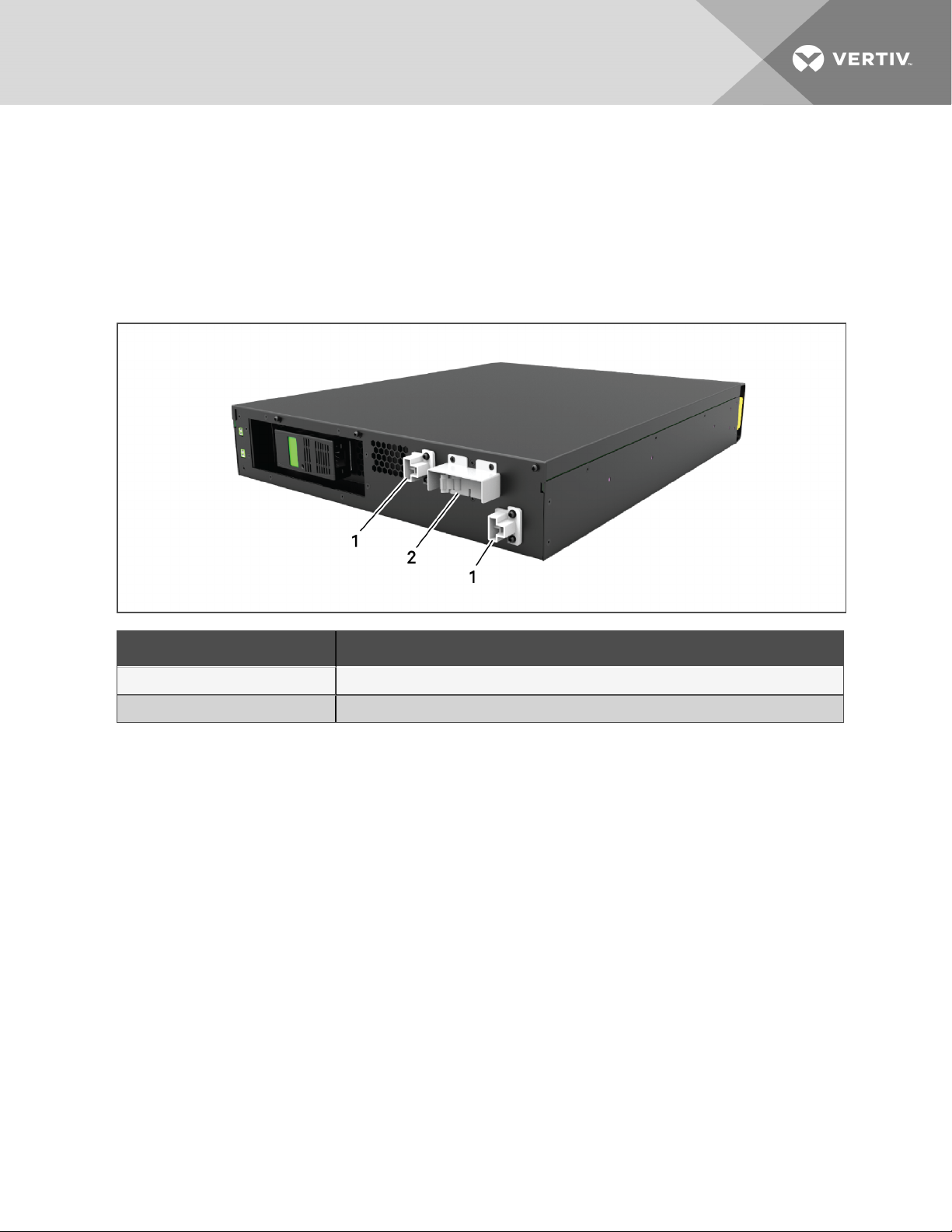
1. Press the button on the left-front of the UPS front panel, and pull the panel open, then, loosen
and remove the screw from the battery door, see Figure 5.1 on the facing page.
2. Lay the battery door and screw aside for reassembly.
3. Grasp the battery handle, and pull out the battery pack, see Figure 5.1 on the facing page.
4. Unpack the replacement battery pack, taking care not to damage the packaging to re-use
when disposing of the old battery.
5. Compare the new and old battery pack to make sure they are the same type and model. If so,
proceed with step 6. If they are different, stop and contact your Vertiv representative, or
Technical Support, http://www.Vertiv.com/en-us/support/.
6. Line-up and slowly push-in each replacement battery pack. The battery is fully-inserted if the
battery door fits flush against the UPS.
7. Re-attach the battery door with the screw, and replace the front cover.
52
Vertiv | Liebert® GXT5™ Installer/UserGuide
Page 57

8. Activate the new battery pack(s) using the operating/display panel:
NOTE: The display menus and functions are described in Operation and Display Panel on page29.
• From the main menu, select Settings, then the Monitoring tab and verify that the date
and time are correct. If the date or time need correction, see Setting the Date and Time
on page49.
• Select the Battery tab, use the arrows to select Replace Battery, and press Enter.
The replaced battery packs are activated.
• Use ESC to return to the main display.
Figure 5.1 Replacing the Battery Pack
5 Maintenance
ITEM DESCRIPTION
1 Battery pack
2 Battery door
3 Front panel
5.2 Charging Batteries
The batteries are valve-regulated, non-spillable, lead acid and should be kept charged to attain their
design life. The UPS charges the batteries continuously when it is connected to the utility input power.
If the UPS will be stored for a long time, We recommend connecting the UPS to input power for at least 24
hours every 4 to 6months to ensure full recharge of the batteries.
53
Page 58

5.3 Checking UPS Operation
NOTE: Operation-check procedures may interrupt power supply to the connected load.
We recommend checking the UPS operation once every 6months.
Back-up the load data before conducting the check.
1. Press the power button to check the indicators and display function.
2. Check for alarm or fault indicators on the operation/display panel.
3. Make sure that there are no audible or silenced alarms.
4. Select the Setting menu, and look at the log for alarm and fault history.
5. Check the operating mode for Normalmode. If the UPS is operating in Bypass mode, contact
Vertiv Technical Support.
6. Check to see if batteries are discharging (operating in Battery mode) and utility power is
normal. If so, contact Vertiv Technical Support.
5.4 Cleaning the UPS
WARNING! Risk of electric shock. Can cause injury or death. Disconnect all local and remote
electric power supplies before working with the UPS. Ensure that the unit is shut down and
power has been disconnected before beginning any maintenance.
WARNING! Risk of electric shock. Can cause injury or death. Hazardous mains and/or battery
voltage exists behind the protective cover No user accessible parts are located behind the
protective covers that require a tool for removal. Only qualified service personnel are
authorized to remove such covers. If maintenance for rack is needed, notice that the neutral
line is live.
The UPS requires no internal cleaning. If the outside of the UPS becomes dusty, wipe with a dry cloth. Do
not use liquid or aerosol cleaners. Do not insert any objects into the ventilation holes or other openings in
the UPS.
54
Vertiv | Liebert® GXT5™ Installer/UserGuide
Page 59

6 TROUBLESHOOTING
This section indicates various UPS symptoms you may encounter and provides a troubleshooting guide in
the event the UPS develops a problem. Use the following information to determine whether external
factors caused the problem and how to remedy the situation.
6.1 Symptoms that Require Troubleshooting
The following symptoms indicate the UPS is malfunctioning:
• The relative indicators illuminate, indicating the UPS has detected a problem.
• An alarm buzzer sounds, alerting the user that the UPS requires attention.
6.2 Audible Alarm (Buzzer)
An audible alarm accompanies various events during UPS operations. Table 6.1 below, describes the
sounds and their meaning. To silence an alarm, see Silencingthe Audible Alarm on page25.
Table 6.1 Audible-alarm Descriptions
SOUND INDI CATES:
Continuous beep Generated when aU PS fault appears, such as afuse or hardware failure.
One beep every 0.5 seconds Generated when aUPS critical alarm appears, such as on inverter overload.
One beep every 1 second Generated when a UPS criticalalarm appears, such as on battery low voltage.
One beep every 3.3 seconds Generated when aUPS generalalarm appears.
NOTE: When an alarm is indicated, an alarm message is logged. Table 4.4 on page42, describes the
alarm messages you may see. When a fault is indicated, front-panel display list the fault, which are
described in Table 6.2 below.
6.2.1 Faults
When the fault indicator is illuminated, the LCD displays the fault. The faults are described in Table 6.2
below.
Table 6.2 Description of displayed faults
DISPLAYED FAULT CAUSE CORREC TIVE STEPS
Battery test fail The battery is bad or weak. Contact technical support.
Rectifier fault A rectifier failure occurred. Contact technical support.
Inverter overload,
Bypassovercurrent
Inverter fault The inverter is faulty. Contact technical support.
Battery aged The battery is bad or weak. Replace the battery.
Output short The output connection isshort-c ircuited.
The UPS is overloaded, Bypass is over current.
Reduce the load and c ontact technical
support.
Shut-down the equipment and contact
technical support.
DCbus fail The DCbus is faulty. Contact technical support.
6 Troubleshooting
55
Page 60

Table 6.2 Description of displayed faults (continued)
DISPLAYED FAULT CAUSE CORREC TIVE STEPS
System overtemp
Charger fault The charger is faulty. Contact technical support.
Fan fault At least one fan is faulty. Contact technical support.
DC/DC fault A DC-DC charger failure occurred. Contact technical support.
Over-temperature condition in the UPS. The UPS will
transfer to bypassmode.
Reduce the load and c ontact technical
support.
6.3 Troubleshooting UPS Issues
In the event of an issue with the UPS, refer to Table 6.3 below, to determine the cause and solution. If the
fault persists, contact Vertiv Technical Support. Visit the GXT5 product page at www.Vertiv.com for
contact information.
When reporting a UPS issue to Vertiv, include the UPS model and serial number. These are located in
several places for your ease of location:
• on the top panel (rack mount orientation)
• the left side (tower orientation)
• the rear panel
• on the front of the unit behind the front plastic bezel
• on the LCD select Main Menu > About.
Table 6.3 Troubleshooting
PROBLEM CAUSE SOLUTION
UPS fails to
start
UPS has
reduced
battery
backup time
UPS is shortcircuited or
overloaded
Batteries are not
charged enough or
not connected
Batteries are not
fully charged
UPS is overloaded Check loadlevel indicator and reduce the load on the UPS.
Batteries may not be
able to hold afull
charge due to age
Ensure UPS is Off. Disconnect all loads and ensure nothingis lodged in output receptacles.
Ensure loads are not defective or shorted internally.
Check to ensure the internal battery is connected. If it isnot, make the connection and try to
start the unit. If the battery is connected, leave the UPS connected to input power for
24hours to recharge batteries, then try to start the unit.
Keep UPS plugged incontinuouslyat least 24 hours to recharge batteries.
Replace batteries. Contact your Vertiv representative or Vertiv Tec hnical Support for
replacement battery kit.
56
Vertiv | Liebert® GXT5™ Installer/UserGuide
Page 61

7 SPECIFICATIONS
Table 7.1 UPS Specifications, 750VA and 1000 VA models
MODEL GXT5- 750IRT2UXL 750IRT2UXLE 1000IRT2UXL 1000IRT2UXLE
RATING 750VA/750W 1000VA/1000W
Dimensions, D×W×H, in.(mm)
Unit 15.7 x16.9 x 3.4 (400 x 430 x 85)
Shipping 24.3 x 22.4 x 10.3 (617x 570 x262)
Weight, lb.(kg)
Unit 36.3 (16.5)
Shipping 51.7 (23.5) 46.2 (21) 51.7 (23.5) 46.2 (21)
Input AC
Voltage Range(typical) 230VAC nominal; variable based on output load
90%~ 100% loading 168~ 177VAC/288VAC
70%~ 90% loading 150 ~168VAC/288VAC
28%~ 70% loading 115~ 150VAC/288VAC
0~ 28% loading 115VAC/288VAC
Frequency 40Hz ~ 70Hz; Auto Sensing
Input Power Cord C14
Output AC
Output Receptacles C13×8
Voltage 200/208/220/230/240VAC (user-configurable); ±3%
Waveform Sine wave
Utility(AC) Model Overload >200% for 250ms; 150- 200% for 2 seconds; 125- 150% for 50 seconds; 105-125% 60 seconds;
Internal Charger
Charging current Nominal2 .2 A; Maximum 8A
Battery
Type Valve-regulated, non-spillable, lead acid
Qty×V×Rating 3 × 12V × 9.0Ah
Battery Mfr./Part# LEOCH/DJW12-9.0
Backup time See Battery Run Times on page63.
Recharge Time
Environmental Requirements
3 Hours to 90% capacityafter fulldischarge with 100% load tillUPS auto-shutdown (Internal Batteries
Only)
7 Specifications
57
Page 62

Table 7.1 UPS Specifications, 750VA and 1000 VA models (continued)
MODEL GXT5- 750IRT2UXL 750IRT2UXLE 1000IRT2UXL 1000IRT2UXLE
RATING 750VA/750W 1000VA/1000W
Operating Temperature,
°F (°C)
Storage Temperature, °F
+32 to +122 (0 to 50); Operating temperature maybe increased to 122°F (50°C with a10% de-ratingof
the output power
(°C)
-4to +140 (-20 to 60)( contain batteries willbe from -15 to 40°C.)
Relative Humidity 0% to 95%, non-condensing
Operating Elevation Up to 10,000 ft. (3000m) at 77ºF (25ºC) without derating
Audible Noise <46dBA max@ 3ft. (1m) front and sides <43dBA max @ 3ft. (1m) rear
Agency
EN 62040-1:2008+A1:2013;
Safety
GSmark;
UL 1778 5th Edition and CSA 2 2.2 No. 107.1
EN 62040-2:2006
EMC
EN 61000-3-2:2014
EN 61000-3-3:2013
Transportation ISTAProcedure 1A
Surge Immunity ANSI C62.41 Category B IEC61000-4-5 Surges/Lightning
RFI/EMI CISPR22 Class A
58
Vertiv | Liebert® GXT5™ Installer/UserGuide
Page 63

Table 7.2 UPS Specifications, 1500VA and 2000VA Models
MODEL GXT5- 1500IRT2UXL 1500IRT2UXLE 2000IRT2UXL 2000IRT2UXLE
RATING 1500VA/1 500W 1000VA/1000W
Dimensions, D×W×H, in.(mm)
Unit 18.5×16.9×3.4(470×430×85)
Shipping 24.3 ×22.4 x10.3(617 x 570 x 262)
Weight, lb.(kg)
Unit 46.2 (21)
Shipping 61.6 (28) 56.1 (25.5) 61.6 (28) 56.1 (25.5)
Input AC
Voltage Range(typical) 230VAC nominal; variable based on output load
90%~ 100% loading 168~177VAC/288VAC
70%~ 90% loading 150 ~168VAC/288VAC
28%~ 70% loading 115~ 150VAC/288VAC
0~ 28% loading 115VAC/288VAC
Frequency 40Hz ~ 70Hz; Auto Sensing
Input Power Cord C14 C20
Output AC
Output Receptacles C13×8
Voltage 200/208/220/230/240VAC (user-configurable); ±3%
Waveform Sine wave
Utility(AC) Model
Overload
>200% for 250ms; 150- 200% for 2 seconds; 125- 150% for 50 seconds; 105-125% 60 seconds;
Internal Charger
Charging current Nominal 2.2 A; Maximum 8A
Battery
Type Valve-regulated, non-spillable, lead acid
Qty×V×Rating 4 × 12V × 9.0Ah
Battery Mfr./Part# LEOCH/DJW12-9.0
Backup time See Battery Run Times on page63.
Recharge Time ) 4 Hours to 90% c apacityafter fulldischarge with 100% load tillU PS auto-shutdown (Internal Batteries Only
Environmental Requirements
Operating
Temperature, °F (°C)
+32 to +122 (0 to 50); Operating temperature maybe increased to 122°F (50°C with a10% de-ratingof the
output power
7 Specifications
Storage Temperature,
°F (°C)
-4to +140 (-20 to 60)( contain batteries willbe from -15 to 40°C.)
59
Page 64

Table 7.2 UPS Specifications, 1500VA and 2000VA Models (continued)
MODEL GXT5- 1500IRT2UXL 1500IRT2UXLE 2000IRT2UXL 2000IRT2UXLE
RATING 1500VA/1 500W 1000VA/1000W
Relative Humidity 0% to 95%, non-condensing
Operating Elevation Up to 10,000 ft. (3000m) at 77ºF (25ºC) without derating
Audible Noise
<46dBA max@ 3ft. (1m) front and sides <45dBA
max@ 3ft. (1m) rear
<48dBA max @ 3ft. (1m) front and sides <48dBA max
Agency
EN 62040-1:2008+A1:2013;
Safety
GSmark;
UL 1778 5th Edition and CSA 2 2.2 No. 107.1
EN 62040-2:2006
EMC
EN 61000-3-2:2014
EN 61000-3-3:2013
Transportation ISTA Procedure 1A
Surge Immunity ANSI C62.41 Category B IEC61000-4-5 Surges/Lightning
RFI/EMI CISPR22 Class A
@ 3ft. (1m)rear
60
Vertiv | Liebert® GXT5™ Installer/UserGuide
Page 65

Table 7.3 UPS Specifications, 3000VA Models
MODEL GXT5- 3000IRT2UXL 3000IRT2UXLE 3KL620RT2UXL 3KL630RT2UXL
RATING 3000VA/3000W 3000VA/2700W 3000VA/3000W
Dimensions, D×W×H, in.(mm)
Unit 21.3 x 16.9 x3.4(540 × 430 × 85)
Shipping 28.2 x 22.4 x10.3(717 x570 x262)
Weight, lb.(Kg)
Unit 62 (28.2) 65.1 (29.6) 67.1 (30.5)
Shipping 79.2 (36) 72.6 (33) 79.2 (36) 80.5 (36.6)
Input AC
Voltage Range
(typical)
90%~ 100%
loading
70%~ 90%
loading
28%~ 70%
loading
230VAC nominal; variable based on output load 208VAC nominal; variable based on output load
184~ 196VAC/288VAC 182~ 191VAC/288VAC
161 ~184VAC/288VAC 164 ~182VAC/288VAC
115~ 161VAC/288VAC 129~ 164VAC/288VAC
0~ 28% loading 115VAC/288VAC 129VAC/288VAC
Frequency 40Hz ~70Hz; Auto Sensing
Input Power Cord C20 L6-20P L6-30P
Output AC
Output
Receptacles
C13×6&C19 L6-20R×2&L6-15R*2 L6-30R×2&L6-15R*2
Voltage 200/208/220/230/240VAC (user-configurable); ±3% 208VAC;±3%
Waveform Sine wave
Utility(AC) Model
Overload
>200% for 250ms; 150- 200% for 2 seconds; 125- 150%
for 50 seconds; 105-125% 60 seconds;
>200% for 250ms; 150- 200% for 2 seconds; 125-
150% for 10 seconds; 105-125% 15 seconds;
Internal Charger
7 Specifications
Charging current Nominal2.2 A; Maximum 8A
Battery
Type Valve-regulated, non-spillable, lead acid
Qty×V×Rating 6 × 12V × 9.0Ah
Battery
Mfr./Part#
LEOCH/DJW12-9.0
Backup time See Battery Run Times on page63.
Recharge Time 3 Hours to 90% capacityafter fulldischarge with 100% load tillUPS auto-shutdown (Internal Batteries Only)
61
Page 66

Table 7.3 UPS Specifications, 3000VA Models (continued)
MODEL GXT5- 3000IRT2UXL 3000IRT2UXLE 3KL620RT2UXL 3KL630RT2UXL
RATING 3000VA/3000W 3000VA/2700W 3000VA/3000W
Environmental Requirements
Operating
Temperature, °F
(°C)
+32 to +122 (0 to 50); Operating temperature maybe increased to 122°F (50°C with a10% de-ratingof the
output power
Storage
Temperature, °F
-4to +140 (-20 to 60)( contain batteries willbe from -15 to 40°C.)
(°C)
Relative Humidity 0% to 95%, non-condensing
Operating
Elevation
Up to 10,000 ft. (3000m) at 77ºF (25ºC) without derating
Audible Noise <48dBA max @ 3ft. (1m) front and sides <48dBA max@ 3ft. (1m) rear
Agency
EN 62040-1:2008+A1:2013;
Safety
GSmark;
UL 1778 5th Edition and CSA 2 2.2 No. 107.1
EN 62040-2:2006
EMC
EN 61000-3-2:2014
EN 61000-3-3:2013
Transportation ISTAProcedure 1A
Surge Immunity ANSI C62.41 Category B IEC 61000-4-5 Surges/Lightning
RFI/EMI CISPR22 Class A
62
Vertiv | Liebert® GXT5™ Installer/UserGuide
Page 67

Table 7.4 External Battery Cabinet Specifications
MODEL NUMBER: GXT5- EBC36VRT2U EBC36VRT2UE EBC48VRT2U EBC48VRT2UE EBC72VRT2U EBC72VRT2U
USED W/UPS MODE L: 750 – 1 ,000 VA 1,500 – 2,000 VA 3,000 VA
Dimensions, D×W×H, in.(mm)
Unit
Shipping 24.3 x 22.4 x10.3 (617x 570 x 262)
Weight, lb.(Kg)
Unit 49.72 (22.6) 63.36 (28.8) 90.64 (41.2)
Shipping 63.14 (28.7) 57.86 (26.3) 77(35) 71.72 (32.6) 104.72 (47.6) 99.22 (45.1)
Battery
Type Valve-regulated, non-spillable, lead acid
Qty×V×Rating 2×3 × 12V × 9.0Ah 2×4 × 12V × 9.0Ah 2×6 × 12V × 9.0Ah
Battery Mfr./Part# LEOCH/DJW12-9.0
Backup time See Battery Run Times below.
Environmental Requirements
Operating Temperature,
°F (°C)
Storage Temperature, °F
(°C)
Relative Humidity 0% to 95%, non-condensing
14.6 x 16.9 x 3.3
(370 × 430 × 85)
32 to 104 (0 to 40)
5 to 104 (-15 to 40) High ambient temperatures willreduce battery life
19.7 x 16.9x 3.3
(49 7 × 430 × 85)
23.7 x 16.9 x 3.3
(602 × 430 × 85)
28.2x224x10.3
(717x570x262)
7 Specifications
Operating Elevation Up to 10,000 ft. (3000m) at 77ºF (25ºC) without derating
Agency
EN 62040-1:2008+A1:2013;
Safety
UL 1778 5th Edition and CSA 2 2.2 No. 107.1
EMC
Safety UL 1778 5th Edition and CSA 22.2 No. 107.1
Transportation ISTA Procedure 1A
Surge Immunity ANSI C62.41 Category B
RFI/EMI FCC Part 15 (Class A)
GSmark;
EN 62040-2:2006
EN 61000-3-2:2014
EN 61000-3-3:2013
7.1 Battery Run Times
NOTE: Run times in this table are approximate. Times are based on new, fully-charged, standard
battery modules at a temperature of 77°F (25°C) with 100% resistive UPS loading. Run times listed
above can vary by ±5% due to manufacturing variances of the individual batteries.
63
Page 68

Table 7.5 Battery Run Time in Minutes
NO. OF EBCS
0
(UPS only)
LOAD
PERCE NTAGE
OF C APACITY
750VA 1000VA 1500VA 2000VA 3000VA
10% 118 92.5 88 66.5 70
20% 63.5 47 42.5 30 31.5
30% 41 29 25.5 17.5 18.5
40% 29 20 17.5 12 12.5
50% 21.5 15 13 9 9
60% 17 11.5 10.5 7 7
70% 14 9.5 8.5 5.5 6
80% 11.5 8 7 4.5 4.5
90% 10 7 6 3.5 4
100% 8.5 6 5 3 3
10% 421 330 314 237 249.5
20% 226 168.5 154 113.5 117.5
30% 148 110.5 100.5 74.5 77.5
40% 110.5 82.5 74.5 55 56.5
+1 EBC
+2 EBC
50% 88 65 59 42 43.5
60% 73 53.5 48 33.5 34.5
70% 62 44.5 39.5 27.5 28
80% 53.5 38 33.5 23 23.5
90% 46.5 33 28.5 19.5 20
100% 41 28.5 25 17 17
10% 727 575.5 549 420 441
20% 402 305.5 281.5 208 216.5
30% 272 201.5 183 132 137
40% 201.5 146.5 132 98.5 101.5
50% 158 116 105.5 78 80
60% 128.5 96 87.5 64 65.5
70% 110 82 74 54 55.5
80% 96 71 64 46 47
90% 85 63 56 40 40.5
100% 76 56 49.5 35 35.5
64
Vertiv | Liebert® GXT5™ Installer/UserGuide
Page 69

Table 7.5 Battery Run Time in Minutes (continued)
NO. OF EBCS
+3 EBC
LOAD
PERCE NTAGE
OF C APACITY
750VA 1000VA 1500VA 2000VA 3000VA
10% 1032.5 820.5 783.5 603.5 632.5
20% 578 443 409 306.5 318
30% 396 297.5 271 199.5 207
40% 297.5 220.5 199.5 144 148.5
50% 236 172.5 155.5 113.5 116.5
60% 194 140 127 94 96
70% 163.5 119 108 79.5 81.5
80% 140 104 94 69 70.5
90% 123.5 92.5 82.5 60.5 61.5
100% 111 82.5 74 54 54.5
10% 1338.5 1066 1018 786.5 824
20% 754 580.5 537 404.5 419.5
30% 519.5 393.5 359.5 267 277
40% 393.5 294 267 196 202
+4 EBC
+5 EBC
50% 314.5 232.5 210.5 152 156
60% 260 191 172 124 127
70% 221 160.5 143.5 105.5 108
80% 191 137.5 124 91.5 94
90% 167.5 122 109.5 81 82.5
100% 148.5 109 98 72 73
10% 1644 1311 1252.5 969,5 1015.5
20% 930 718 664.5 503 521
30% 643.5 489 447.5 335 347
40% 489 368 335 248 255
50% 392.5 292.5 265.5 194.5 199.5
60% 326.5 241.5 219 157.5 162
70% 278 204.5 184 131.5 135
80% 241.5 176.5 157.5 114.5 117
90% 213 154.5 137 101 103
100% 190 136.5 122.5 90.5 92
7 Specifications
65
Page 70

Table 7.5 Battery Run Time in Minutes (continued)
NO. OF EBCS
+6 EBC
LOAD
PERCE NTAGE
OF C APACITY
750VA 1000VA 1500VA 2000VA 3000VA
10% 1950 1556.5 1487 1152.5 1207.5
20% 1106 855 792.5 601.5 622.5
30% 767.5 585 536 402.5 417
40% 585 441.5 402.5 300 308.5
50% 470.5 353 320.5 236.5 242.5
60% 392.5 292.5 265.5 193 198
70% 335.5 249 224 161.5 166.5
80% 292.5 215.5 193 138 142
90% 258.5 189.5 168.5 121.5 124
100% 231 168 149 109 110.5
10% 2255.5 1801.5 1721.5 1336 1399
20% 1282 992.5 920 699.5 724
30% 891 680.5 624 470 487
40% 680.5 515.5 470 352 361.5
+7EBC
+8 EBC
50% 549 413 376 279 285.5
60% 458.5 343.5 312 228.5 234.5
70% 393 293 264.5 192.5 197.5
80% 343.5 254.5 228.5 165 169.5
90% 304 224.5 200.5 143.5 146.5
100% 272.5 199.5 177.5 127.5 129.5
10% 2561.5 2047 1956 1519 1590.5
20% 1457.5 1130 1047.5 798 826
30% 1015 776.5 712.5 538 557
40% 776.5 589 538 404 415
50% 627 473 431 321 32 8.5
60% 525 394 358.5 264 270.5
70% 450.5 337 304.5 223 229
80% 394 293.5 264 192 197
90% 349.5 259.5 232 168 171.5
100% 314 231.5 206.5 148.5 150.5
66
Vertiv | Liebert® GXT5™ Installer/UserGuide
Page 71

Table 7.5 Battery Run Time in Minutes (continued)
NO. OF EBCS
+9 EBC
LOAD
PERCE NTAGE
OF C APACITY
750VA 1000VA 1500VA 2000VA 3000VA
10% 2867 2292 2190.5 1702 1782
20% 1633.5 1267 1175.5 896 927.5
30% 1139 872 800.5 605.5 627
40% 872 662.5 605.5 456 468
50% 705.5 533 486 363 371.5
60% 591 445 405.5 299.5 307
70% 508 381 345 253.5 260.5
80% 445 332.5 299.5 219 224.5
90% 395 294.5 264 192 196
100% 355 263 235 170.5 173
10% 3173 2537.5 2425.5 1885.5 1973.5
20% 1809.5 1404.5 1303 994.5 1029
30% 1262.5 968 889 673.5 697
40% 968 736.5 673.5 508 521
+10 EBC
50% 783.5 593 541.5 405.5 414.5
60% 657.5 495.5 452 335 343
70% 565.5 425 385.5 284.5 292
80% 495.5 371.5 335 246 252
90% 441 329.5 295.5 216 220.5
100% 396.5 294.5 264 192.5 195
7 Specifications
67
Page 72

This page intentionally left blank
68
Vertiv | Liebert® GXT5™ Installer/UserGuide
Page 73

APPENDICES
Appendix A: Technical Support
Our Technical Support staff is ready to assist you with any installation or operating issues you may
encounter with your Liebert® product. Please call or e-mail us:
In Europe, Middle East, and Asia:
EMEA Multi-Language Technical support:
e: eoc@vertivco.com
p: Toll free 0080011554499
p: Toll +39 02 98250222
In the United States:
Technical support:
e: liebert.upstech@vertivco.com
p: 1-800-222-5877 menu option 1
Monitoring support:
e: liebert.monitoring@vertivco.com
p: 1-800-222-5877 menu option 2
Warranty support:
e: microups.warranty@vertivco.com
p: 1-800-222-5877 menu option 3
69
Page 74

This page intentionally left blank
70
Vertiv | Liebert® GXT5™ Installer/UserGuide
Page 75

Vertiv | Liebert® GXT5™ Installer/UserGuide
Page 76

Vertiv.com | Vertiv Headquarters, 1050 Dearborn Drive, Columbus, OH, 43085, USA
© 2019 Vertiv Co. Allrights reserved. Vertiv and the Vertivlogo are trademarks or registered trademarks ofVertiv Co. Allother names and logos referred to
are trade names, trademarks or registered trademarks of their respective owners. While every precaution has been taken to ensure accuracy and
completeness herein, Vertiv Co. assumes no responsibility, and disclaims allliability, for damages resultingfrom use ofthis information or for anyerrors or
omissions. Spec ifications are subject to change without notice.
590-1935-501A
 Loading...