

Page 1
Global LCD Panel Exchange Center
www.panelook.com
LP140WH1
Liquid Crystal Display
Product Specification
SPECIFICATION
FOR
APPROVAL
)
(
(
Preliminary Specification
)
Final Specification
ଝ
14.0”W HD TFT LCDTitle
LG Display Co., Ltd.SUPPLIER
LP140WH1*MODEL
TLA1Suffix
SIGNATURE
SIGNATURE
MODEL
ACERCustomer
*When you obtain standard approval,
please use the above model name without suffix
APPROVED BY
SIGNATUREAPPROVED BY
/
/
APPROVED BY
K. S. Kwon / S.Manager
K. S. Kwon / S.Manager
REVIEWED BY
REVIEWED BY
C. I. Kim / Manager
PREPARED BY
/
Please return 1 copy for your confirmation with
your signature and comments.
Ver. 1.0 Oct. 17, 2008
PREPARED BY
J. W. Kim / Engineer
Y. S. Kim / Engineer
Products Engineering Dept.
LG Display Co., Ltd
One step solution for LCD / PDP / OLED panel application: Datasheet, inventory and accessory!
1/ 33
www.panelook.com
Page 2
Global LCD Panel Exchange Center
www.panelook.com
LP140WH1
Liquid Crystal Display
Product Specification
Contents
COVER
CONTENTS
RECORD OF REVISIONS
GENERAL DESCRIPTION1
ABSOLUTE MAXIMUM RATINGS2
ELECTRICAL SPECIFICATIONS3
ELECTRICAL CHARACTREISTICS3-1
INTERFACE CONNECTIONS3-2
LVDS SIGNAL TIMING SPECIFICATION3-3
SIGNAL TIMING SPECIFICATIONS3-3
SIGNAL TIMING WAVEFORMS3-4
COLOR INPUT DATA REFERNECE3-5
POWER SEQUENCE3-6
OPTICAL SFECIFICATIONS4
ITEMNo
Page
1
2
3
4
5
6
7
8-9
9
10
11
12
13-16
MECHANICAL CHARACTERISTICS5
RELIABLITY6
INTERNATIONAL STANDARDS7
SAFETY7-1
EMC7-2
PACKING8
DESIGNATION OF LOT MARK8-1
PACKING FORM8-2
PRECAUTIONS9
APPENDIX. Enhanced Extended Display Identification Data A
Ver. 1.0 Oct. 17, 2008
17-25
26
27
27
28
28
29-30
31-33
2/ 33
One step solution for LCD / PDP / OLED panel application: Datasheet, inventory and accessory!
www.panelook.com
Page 3
Global LCD Panel Exchange Center
www.panelook.com
LP140WH1
Liquid Crystal Display
Product Specification
RECORD OF REVISIONS
29
DescriptionPageRevision DateRevision No
First Draft (Preliminary Specification)-Jun. 17. 20080.0
CN1 Pin #1 update (GROUND ˧ NC)7Aug. 13, 20080.1
Rear view update18Aug. 14, 20080.2
Rear view drawing update18,19Aug. 25, 20080.3
Update color coordinates spec.13
Update Gray scale spec.14
Insert Viewing Angle description page.16
Update Rear view Drawing19
Update color coordinates EDID data (Ver. 0.0 ˧ 0.1)27
Change EDID Checksum (E4 ˧ EC)
EDID
ver
0.0
0.1Update ELECTRICAL CHARACTERISTICS6Sep. 26, 20080.4
1.0Final Draft-Oct. 17, 20081.0
Ver. 1.0 Oct. 17, 2008
One step solution for LCD / PDP / OLED panel application: Datasheet, inventory and accessory!
3/ 33
www.panelook.com
Page 4
Global LCD Panel Exchange Center
1. General Description
The LP140WH1 is a Color Active Matrix Liquid Crystal Display with an integral LED backlight system. The
matrix employs a-Si Thin Film Transistor as the active element. It is a transmissive type display operating in
the normally white mode. This TFT-LCD has 14.0 inches diagonally measured active display area with HD
resolution(768 vertical by 1366 horizontal pixel array). Each pixel is divided into Red, Green and Blue subpixels or dots which are arranged in vertical stripes. Gray scale or the brightness of the sub-pixel color is
determined with a 6-bit gray scale signal for each dot, thus, presenting a palette of more than 262,144
colors.
The LP140WH1 has been designed to apply the interface method that enables low power, high speed, low
EMI.
The LP140WH1 is intended to support applications where thin thickness, low power are critical factors and
graphic displays are important. In combination with the vertical arrangement of the sub-pixels, the
LP140WH1 characteristics provide an excellent flat display for office automation products such as Notebook
PC.
www.panelook.com
LP140WH1
Liquid Crystal Display
Product Specification
ڞکڍ
ڞکڍ
ڔګۄۉ
ڔګۄۉ
ڞک
ڌ
ڰێۀۍٻھۊۉۉۀھۏۊۍٻ
ڏڋ
ګۄۉ
General Features
ڡګڞ
ڡګڞ
ڠڟڤڟٻ
ڠڟڤڟٻ
ڝڧڪڞڦ
ڝڧڪڞڦ
ګڪڲڠڭٻ
ګڪڲڠڭٻ
ڝڧڪڞڦ
ڝڧڪڞڦ
ڧڱڟڮٻځ
ڧڱڟڮٻځ
گۄۈۄۉۂ
گۄۈۄۉۂ
ڞۊۉۏۍۊۇ
ڞۊۉۏۍۊۇ
ڝۇۊھۆ
ڝۇۊھۆ
ڌ
ڢڤګڃڢڼۏۀٻڤۉٻګڼۉۀۇڄ
ڒڑړ
ڌ
ڲڧڠڟٻڜێێ’۔ڃڏړۀڼڄ
گڡگڈڧڞڟٻګڼۉۀۇ
ڃڌڎڑڑٻڳٻڒڑړڄ
ڮۊېۍھۀٻڟۍۄۑۀۍٻڞۄۍھېۄۏ
ڮۊېۍھۀٻڟۍۄۑۀۍٻڞۄۍھېۄۏ
ࣿࣜࣜ ࣜࣜࣜ
14.0 inches diagonalActive Screen Size
323.5(H, typ) ϧ 192.0(V, typ) Ý 5.2(D,max) [mm]Outline Dimension
0.2265mm Ý 0.2265 mmPixel Pitch
1366 horiz. By 768 vert. Pixels RGB strip arrangementPixel Format
6-bit, 262,144 colorsColor Depth
220 cd/m
Total 4.5 Watt(Typ.) @ LCM circuit 1.4 Watt(Typ.), B/L input 3.1 Watt(Typ.)Power Consumption
350g (Max.)Weight
Transmissive mode, normally whiteDisplay Operating Mode
Hard Coating(3H), Glare treatment of the front polarizerSurface Treatment
YesRoHS Comply
2
(Typ.5 point)Luminance, White
ڌڎڑڑ
Ver. 1.0 Oct. 17, 2008
One step solution for LCD / PDP / OLED panel application: Datasheet, inventory and accessory!
4/ 33
www.panelook.com
Page 5
Global LCD Panel Exchange Center
2. Absolute Maximum Ratings
The following are maximum values which, if exceeded, may cause faulty operation or damage to the unit.
www.panelook.com
LP140WH1
Liquid Crystal Display
Product Specification
Table 1. ABSOLUTE MAXIMUM RATINGS
Parameter Notes
Symbol
Values
Units
MaxMin
Power Input Voltage
Operating Temperature
Storage Temperature
Operating Ambient Humidity
OP
Storage Humidity
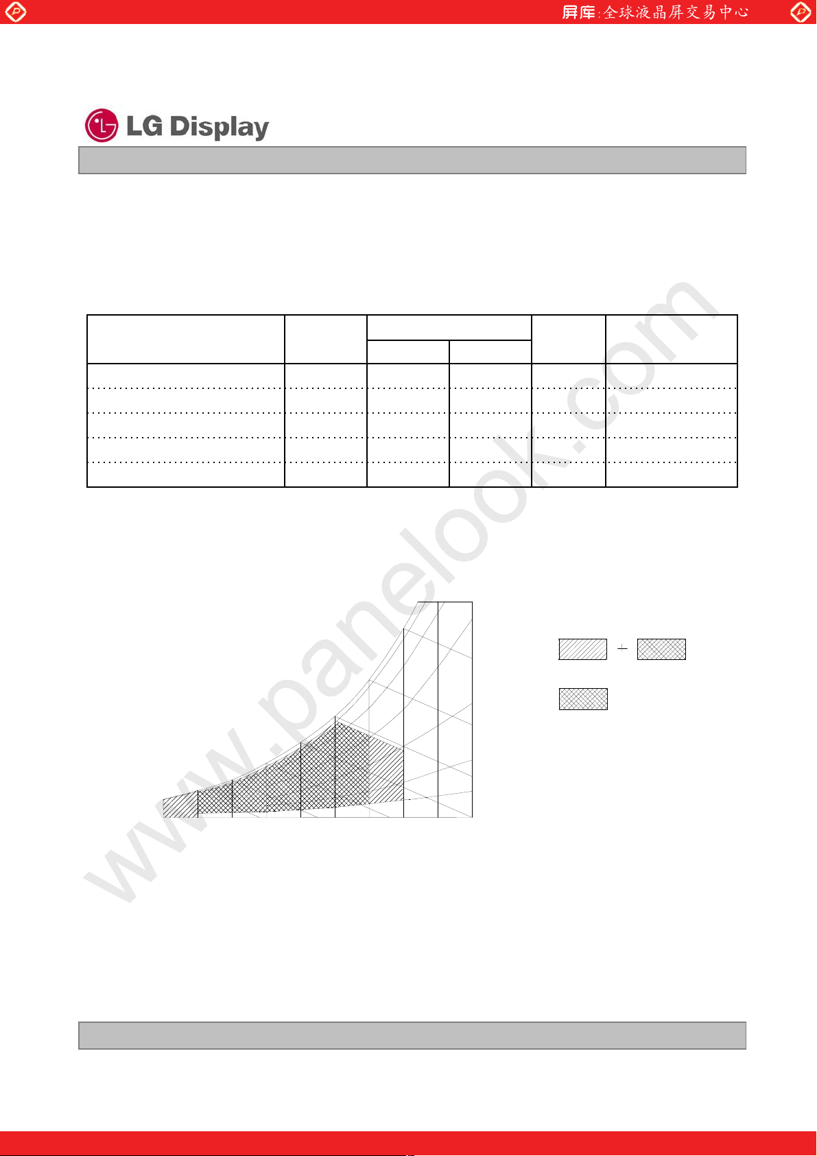
Note : 1. Temperature and relative humidity range are shown in the figure below.
Wet bulb temperature should be 39
Wet Bulb
Temperature [
10
0
20
]
30
qC Max, and no condensation of water.
90% 80%
60
50
40
60%
Humidity[(%)RH]
40%
20%
10%
Storage
Operation
at 25 r 5qCVdc4.0-0.3VCC
1qC500TOP
1qC60-20HST
1%RH9010H
1%RH9010HST
-20
10
20 30 40 50
60 70 800
Dry Bulb Temperature []
Ver. 1.0 Oct. 17, 2008
One step solution for LCD / PDP / OLED panel application: Datasheet, inventory and accessory!
5/ 33
www.panelook.com
Page 6
Global LCD Panel Exchange Center
3. Electrical Specifications
3-1. Electrical Characteristics
The LP140WH1 requires two power inputs. One is employed to power the LCD electronics and to drive the
TFT array and liquid crystal. The second input which powers the LED BL.
Parameter Symbol
MODULE :
Power Supply Input Current
LED Backlight ( With LED Driver )
Operating Current per string
Power Consumption
PWM Input Signal
Frequency
On Duty
Voltage Level
LED_EN
Voltage Level
www.panelook.com
Product Specification
Table 2. ELECTRICAL CHARACTERISTICS
Values
I
CC
LED
LED
PWM
on
PWM
LED_EN
Liquid Crystal Display
MaxTypMin
3.63.33.0VCCPower Supply Input Voltage
V
DC
mA1500IrushInrush Current
V207.0VLED
Hz1000120F
%3D
V2.9V
V2.9V
LP140WH1
NotesUnit
1mA495430-
1Watt1.61.4-PcPower Consumption
2Ohm11010090ZmDifferential Impedance
3mA-20-I
4Watt3.93.6-P
5Hrs--12,000Life Time
Note)
1. The specified current and power consumption are under the Vcc = 3.3V , 25, fv = 60Hz condition
whereas Mosaic pattern is displayed and fv is the frame frequency.
2. This impedance value is needed to proper display and measured form LVDS Tx to the mating connector.
3. The typical operating current is for the typical surface luminance (L
is the current of each LED’s string, LED backlight has 6 strings on it.
I
LED
) in optical characteristics.
WH
4. The LED power consumption shown above includes power of internal LED driver circuit for typical current
condition.
5. The life time is determined as the time at which brightness of LCD is 50% compare to that of initial value
at the typical LED current.
Ver. 1.0 Oct. 17, 2008
6/ 33
One step solution for LCD / PDP / OLED panel application: Datasheet, inventory and accessory!
www.panelook.com
Page 7
Global LCD Panel Exchange Center
3-2. Interface Connections
This LCD employs two interface connections, a 40 pin connector is used for the module electronics interface
and the other connector is used for the integral backlight system.
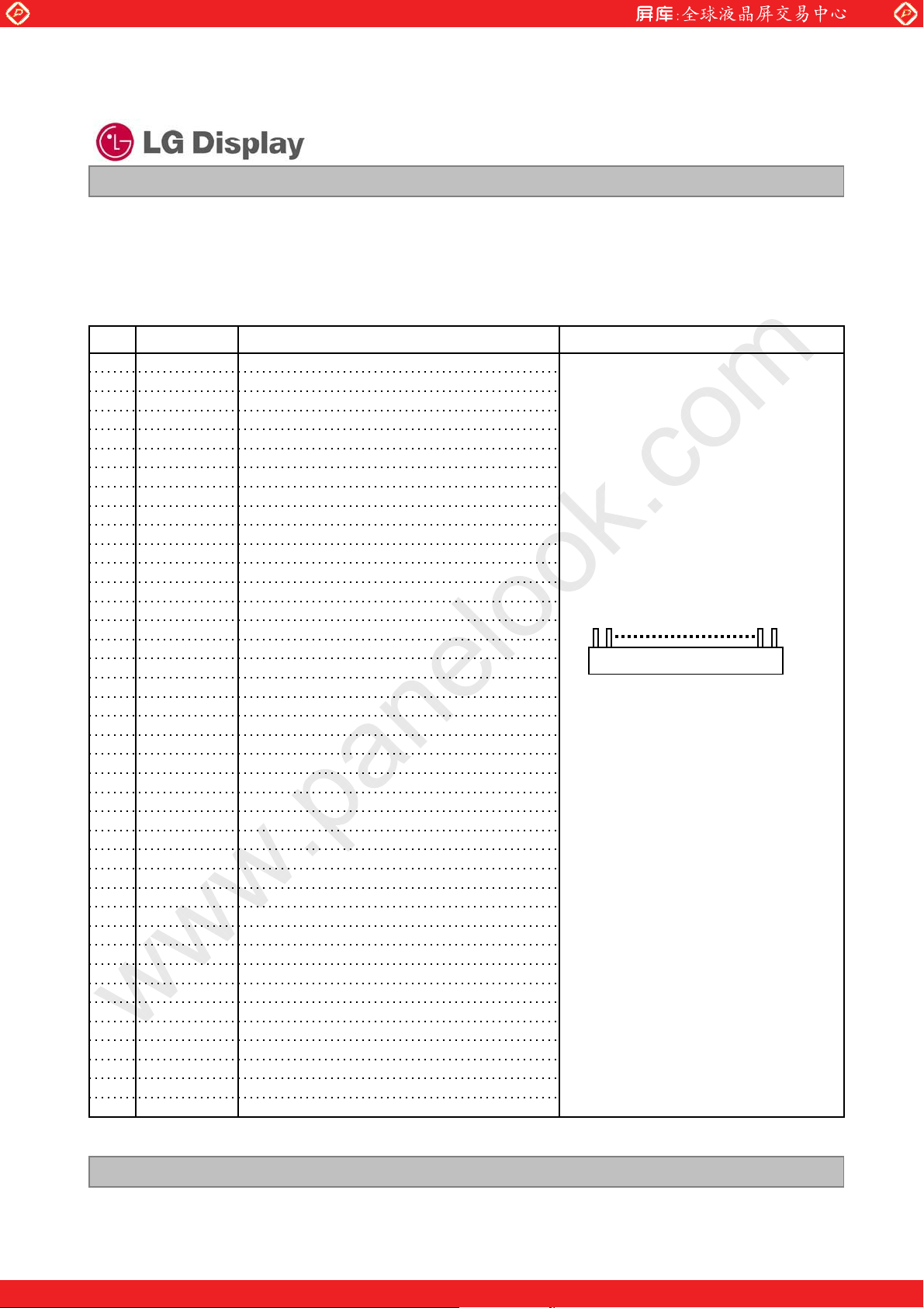
The electronics interface connector is a model CABLINE-VS RECE ASS’Y manufactured by I-PEX.
Table 3. MODULE CONNECTOR PIN CONFIGURATION (CN1)
ReservedNC1
Power Supply, 3.3V Typ.VCC2
Power Supply, 3.3V Typ.VCC3
DDC 3.3V powerV EEDID4
No ConnectionNC5
DDC ClockClk EEDID6
DDC DataDATA EEDID7
Negative LVDS differential data inputOdd_R
0-8
IN
0+9
IN
IN
IN
NC No Connection21
31
32
33
34
35
36
37
38
39
40
Positive LVDS differential data inputOdd_R
GroundGND10
1-11
Negative LVDS differential data inputOdd_R
IN
Positive LVDS differential data inputOdd_R
1+12
GroundGND13
Negative LVDS differential data inputOdd_R
2-14
IN
2+15
Positive LVDS differential data inputOdd_R
GroundGND16
Negative LVDS differential clock inputOdd_CLKIN-17
Positive LVDS differential clock inputOdd_CLKIN+18
GroundGND19
No ConnectionNC20
GroundGND19
No ConnectionNC23
No ConnectionNC24
GroundGND19
No ConnectionNC26
No ConnectionNC27
GroundGND19
No ConnectionNC29
No ConnectionNC30
LED GroundVLED_GND
LED GroundVLED_GND
LED GroundVLED_GND
Reserved NC
PWM for luminance control(200Hz ~ 1000Hz)PWM
Backlight On/Off ControlLED_EN
No Connection (Reserved)NC
LED Power Supply (7V-20V)VLED
LED Power Supply (7V-20V)VLED
LED Power Supply (7V-20V)VLED
www.panelook.com
Product Specification
LP140WH1
Liquid Crystal Display
NotesDescriptionSymbolPin
1, Interface chips
1.1 LCD : SW, SW0624 (LCD Controller)
including LVDS Receiver
1.2 System : THC63LVDF823A
* Pin to Pin compatible with LVDS
2. Connector
2.1 LCD : CABLINE-VS RECE ASS’Y, I-PEX
2.2 Mating : CABLINE-VS PLUG CABLE
2.3 Connector pin arrangement
[W
3, Pin connection for LED IC
1.1 Pin #35 should not connect with Pin #36.
or equivalent
or its compatibles
ASS’Y or equivalent.
X
[LCD Module Rear View]
Ver. 1.0 Oct. 17, 2008
One step solution for LCD / PDP / OLED panel application: Datasheet, inventory and accessory!
7/ 33
www.panelook.com
Page 8
Global LCD Panel Exchange Center
3-3. LVDS Signal Timing Specifications
3-3-1. DC Specification
www.panelook.com
LP140WH1
Liquid Crystal Display
Product Specification
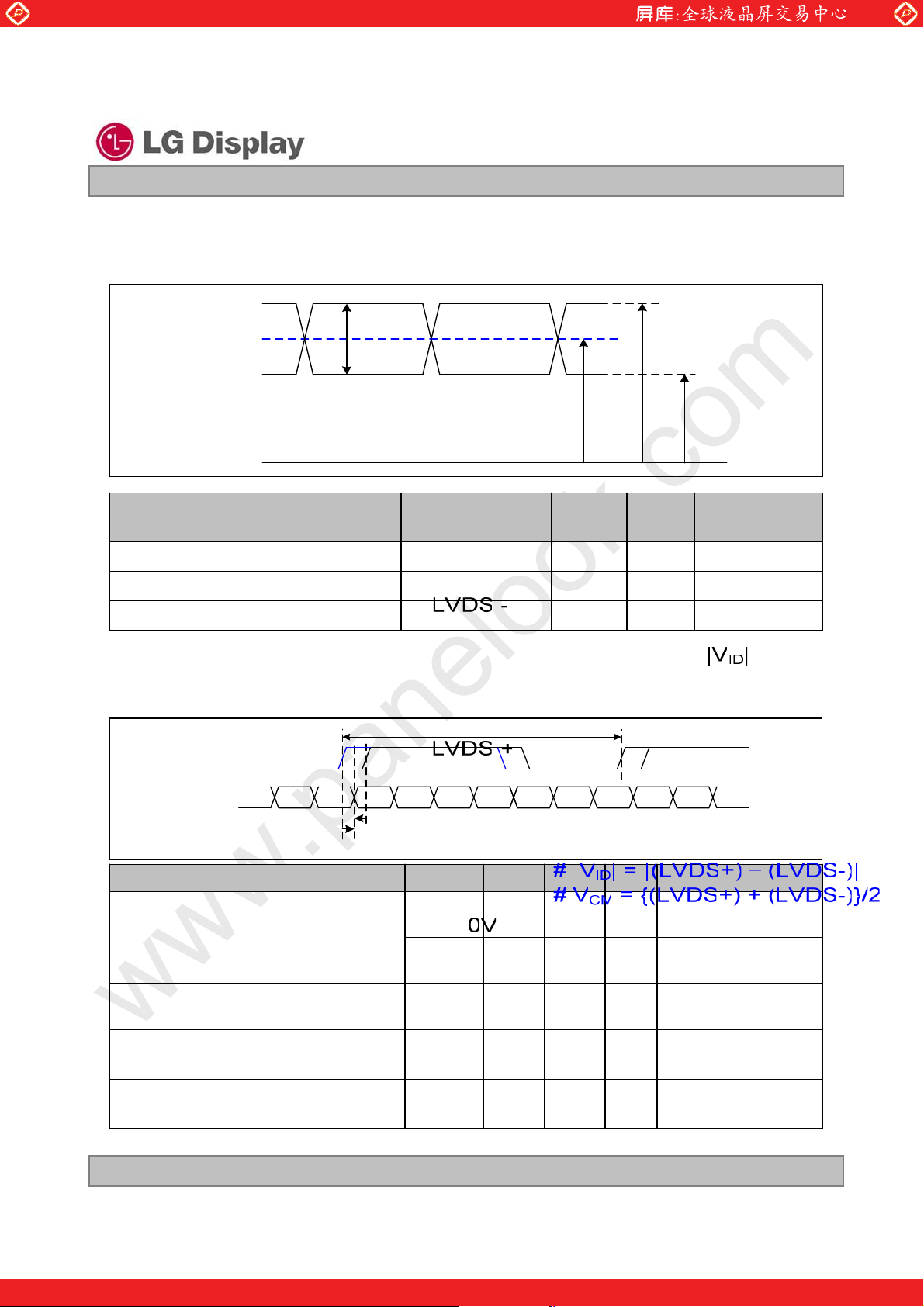
Description
LVDS Common mode Voltage
LVDS Input Voltage Range
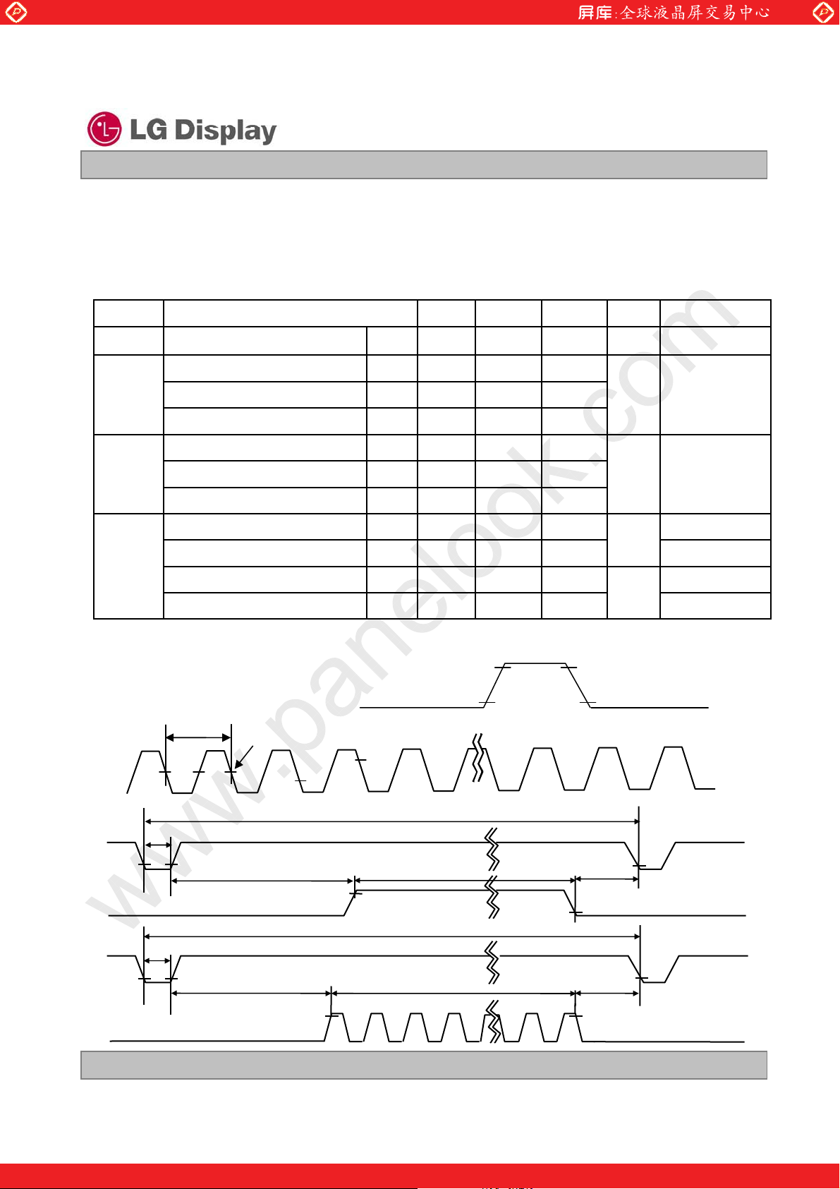
3-3-2. AC Specification
LVDS Clock to Data Skew Margin
Symb
ol
ID
CM
IN
SKEW
SKEW
NotesUnitMaxMin
|LVDS Differential Voltage
-mV600100|V
-V1.80.6V
-V2.10.3V
NotesUnitMaxMinSymbolDescription
85MHz > Fclk ˻
65MHz
65MHz > Fclk ˻
25MHz
- 600
ps+ 400- 400t
ps+ 600t
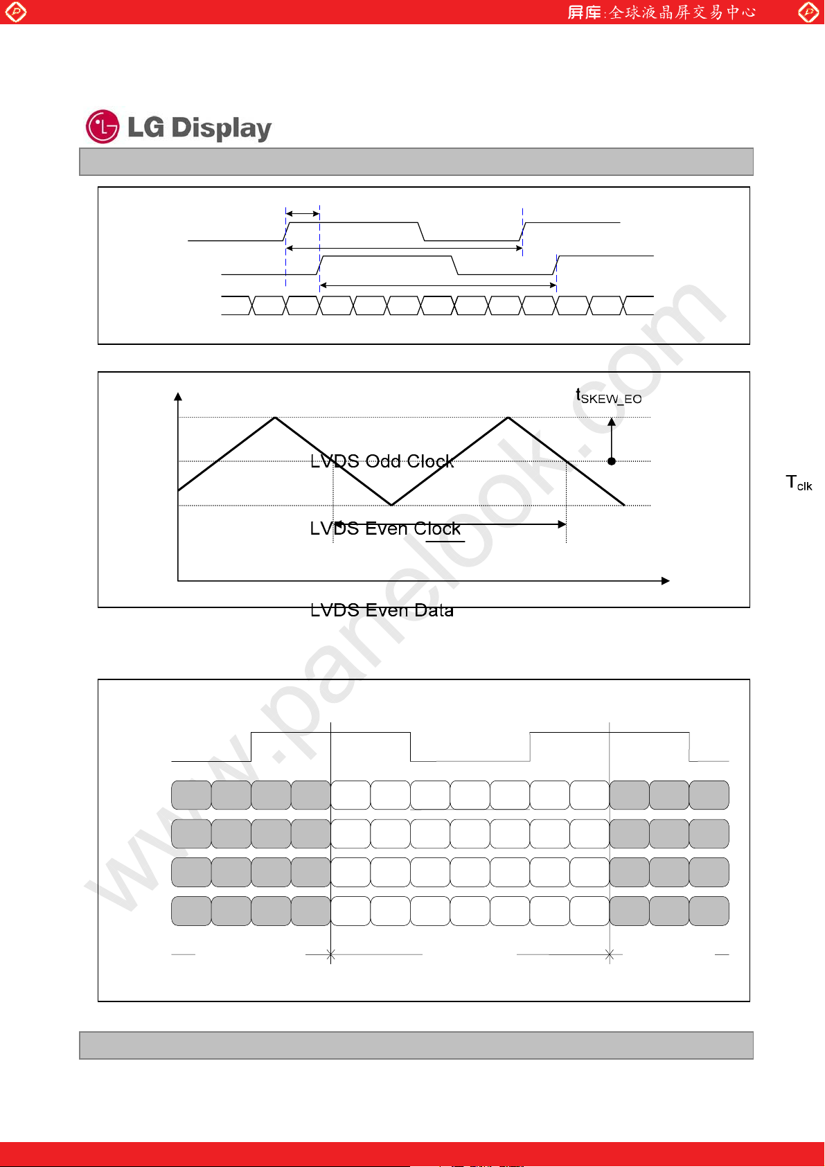
LVDS Clock to Clock Skew Margin (Even
to Odd)
SKEW_EO
Maximum deviation
of input clock frequency during SSC
DEV
Maximum modulation frequency
of input clock during SSC
Ver. 1.0 Oct. 17, 2008
MOD
-1/7
+ 1/7t
T
clk
%· 3-F
KHz200-F
One step solution for LCD / PDP / OLED panel application: Datasheet, inventory and accessory!
-
-
-
8/ 33
www.panelook.com
Page 9
Global LCD Panel Exchange Center
Freq.
www.panelook.com
LP140WH1
Liquid Crystal Display
Product Specification
< Clock skew margin between channel >
F
max
F
center
F
min
3-3-3. Data Format
1) LVDS 1 Port
RCLK+
RA+/-
R3 R2
R1 R0
X
m
tvk
< Spread Spectrum >
G0 R5 R4 R3 R2 R1 R0
m
G0
QGm
kl}
Time
R5 R4
RB+/-
RC+/-
RD+/-
G4 G3
B5 B4
G7 G6
Previous (N-1)th Cycle Next (N+1 )th Cycle
G2 G1
B3 B2
R7 R6
B1 B0 G5 G4 G3 G2 G1
DE VSYNC HSYNC B5 B4 B3 B2
X B7 B6 G7 G6 R7 R6
Current (Nth ) Cycle
B1
DE
X
< LVDS Data Format >
Ver. 1.0 Oct. 17, 2008
One step solution for LCD / PDP / OLED panel application: Datasheet, inventory and accessory!
B0 G5
VSYNC HSYNC
B7 B6
9/ 33
www.panelook.com
Page 10
Global LCD Panel Exchange Center
3-4. Signal Timing Specifications
This is the signal timing required at the input of the User connector. All of the interface signal timing should be
satisfied with the following specifications and specifications of LVDS Tx/Rx for its proper operation.
www.panelook.com
LP140WH1
Liquid Crystal Display
Product Specification
Table 4. TIMING TABLE
NoteUnitMaxTypMinSymbolITEM
FrequencyDCLK
Period
Hsync
Width
Width-Active
Period
Vsync
Width
Width-Active
Horizontal back porch
Data
Enable
Horizontal front porch
Vertical back porch
Vertical front porch
3-5. Signal Timing Waveforms
Data Enable, Hsync, Vsync
DCLK
tCLK
0.5 Vcc
f
CLK
t
HP
WH
WHA
VP
WV
WVA
HBP
HFP
t
VBP
t
VFP
High: 0.7VCC
Low: 0.3VCC
-
MHz-72.3
158615261470
403223t
tCLK
136613661366t
801790779t
852t
tHP
768768768t
1248072t
tCLK
48488t
20148
tHP
531
Condition : VCC =3.3V
t
Hsync
t
WH
t
HBP
HP
tWHA
t
HFP
Data Enable
t
VP
t
WV
Vsync
t
VBP
tWVA
t
VFP
Data Enable
Ver. 1.0 Oct. 17, 2008
One step solution for LCD / PDP / OLED panel application: Datasheet, inventory and accessory!
10 / 33
www.panelook.com
Page 11

Global LCD Panel Exchange Center
3-6. Color Input Data Reference
The brightness of each primary color (red,green and blue) is based on the 6-bit gray scale data input for the
color ; the higher the binary input, the brighter the color. The table below provides a reference for color
versus data input.
www.panelook.com
LP140WH1
Liquid Crystal Display
Product Specification
Table 5. COLOR DATA REFERENCE
Input Color Data
Basic
Color
RED
GREEN
BLUE
Color
Black
Red
Green
Blue
Cyan
Magenta
Yellow
White
RED (00)
RED (01)
…
RED (62)
RED (63)
GREEN (00)
GREEN (01)
...
GREEN (62)
GREEN (63)
BLUE (00)
BLUE (01)
…
BLUE (62)
BLUE (63)
RED
MSB LSB
GREEN
MSB LSB
BLUE
MSB LSB
B5 B4 B3 B2 B1 B0G5 G4 G3 G2 G1 G0R5 R4 R3 R2 R1 R0
0 0 0 0 0 00 0 0 0 0 00 0 0 0 0 0
0 0 0 0 0 00 0 0 0 0 01 1 1 1 1 1
0 0 0 0 0 01 1 1 1 1 10 0 0 0 0 0
1 1 1 1 1 10 0 0 0 0 00 0 0 0 0 0
1 1 1 1 1 11 1 1 1 1 10 0 0 0 0 0
1 1 1 1 1 10 0 0 0 0 01 1 1 1 1 1
0 0 0 0 0 01 1 1 1 1 11 1 1 1 1 1
1 1 1 1 1 11 1 1 1 1 11 1 1 1 1 1
0 0 0 0 0 00 0 0 0 0 00 0 0 0 0 0
0 0 0 0 0 00 0 0 0 0 00 0 0 0 0 1
………
0 0 0 0 0 00 0 0 0 0 01 1 1 1 1 0
0 0 0 0 0 00 0 0 0 0 01 1 1 1 1 1
0 0 0 0 0 00 0 0 0 0 00 0 0 0 0 0
0 0 0 0 0 00 0 0 0 0 10 0 0 0 0 0
………
0 0 0 0 0 01 1 1 1 1 00 0 0 0 0 0
0 0 0 0 0 01 1 1 1 1 10 0 0 0 0 0
0 0 0 0 0 00 0 0 0 0 00 0 0 0 0 0
0 0 0 0 0 10 0 0 0 0 00 0 0 0 0 0
………
1 1 1 1 1 00 0 0 0 0 00 0 0 0 0 0
1 1 1 1 1 10 0 0 0 0 00 0 0 0 0 0
Ver. 1.0 Oct. 17, 2008
One step solution for LCD / PDP / OLED panel application: Datasheet, inventory and accessory!
11 / 33
www.panelook.com
Page 12

Global LCD Panel Exchange Center
3-7. Power Sequence
www.panelook.com
LP140WH1
Liquid Crystal Display
Product Specification
90%
90%
Power Supply For LCD
VCC
Interface Signal,
V
i
(LVDS Signal of Transmitter)
0V
0V
T
T
T
1
2
7
Valid Data
T
3
T
6
10%10%
T
8
T
9
LED En
LED_En
OFFOFF
PWM On
T
5
PWM
OFF
T
4
VLED(LED Power supply) should be turn on before PWM on signal and turn off after PWM off signal.
PWM On signal should be fixed PWM duty or DC, not variable duty signal while PWM on.
Table 6. POWER SEQUENCE TABLE
UnitsValueParameter
Max.Typ.Min.
1
2
3
4
5
6
7
8
9
-0T
-0T
T
3
6
(ms)10-0.5T
(ms)50-0T
(ms)--200T
(ms)
(ms)T
(ms)--200T
(ms)50-0T
(ms)10-3T
(ms)--400T
Note)
1. Valid Data is Data to meet “3-3. LVDS Signal Timing Specifications”
2. Please avoid floating state of interface signal at invalid period.
3. When the interface signal is invalid, be sure to pull down the power supply for LCD VCC to 0V.
4. LED power must be turn on after power supply for LCD and interface signal are valid.
Ver. 1.0 Oct. 17, 2008
12 / 33
One step solution for LCD / PDP / OLED panel application: Datasheet, inventory and accessory!
www.panelook.com
Page 13

Global LCD Panel Exchange Center
4. Optical Specification
Optical characteristics are determined after the unit has been ‘ON’ and stable for approximately 30 minutes in
a dark environment at 25
at a viewing angle of
FIG. 1 presents additional information concerning the measurement equipment and method.
qC. The values specified are at an approximate distance 50cm from the LCD surface
) and 4 equal to 0q.
FIG. 1 Optical Characteristic Measurement Equipment and Method
www.panelook.com
LP140WH1
Liquid Crystal Display
Product Specification
Optical Stage(x,y)
Parameter Symbol NotesUnits
Surface Luminance, white
Luminance Variation
Response Time
Color Coordinates
RED
GREEN
BLUE
x axis, right()=0q) degree--404r
x axis, left ()=180q)
y axis, up ()=90q)
y axis, down ()=270q)
LCD Module
50cm
Table 7. OPTICAL CHARACTERISTICS
Ta=25qC, VCC=3.3V, fV=60Hz, f
Values
WH
WHITE
TrR+ Tr
D
RX
RY
GX
GY
BX
BY
0.6480.6180.588
0.3850.3550.325
0.3650.3350.305
0.6140.5840.554
0.1800.1500.120
0.1390.1090.079
0.3430.3130.283WXWHITE
0.3590.3290.299WY
Pritchard 880 or
equivalent
MaxTypMin
-220190L
degree--404l
degree--104u
degree--304d
= 72.3MHz , I
CLK
2
%-60-C/GColor Gamut
= 20 mA
LED
1--500CRContrast Ratio
2cd/m
31.61.4-G
4ms158-
5Viewing Angle
6Gray Scale
Ver. 1.0 Oct. 17, 2008
One step solution for LCD / PDP / OLED panel application: Datasheet, inventory and accessory!
13 / 33
www.panelook.com
Page 14

Global LCD Panel Exchange Center
Note)
1. Contrast Ratio(CR) is defined mathematically as
Surface Luminance with all white pixels
Contrast Ratio =
Surface Luminance with all black pixels
2. Surface luminance is the average of 5 point across the LCD surface 50cm from the surface with
all pixels displaying white. For more information see FIG 1.
= Average(L1,L2, … L5)
L
WH
www.panelook.com
LP140WH1
Liquid Crystal Display
Product Specification
3. The variation in surface luminance , The panel total variation (
G
) is determined by measuring L
WHITE
N
at each test position 1 through 13 and then defined as followed numerical formula.
For more information see FIG 2.
Maximum(L
G
WHITE
=
Minimum(L
4. Response time is the time required for the display to transition from white to black (rise time, Tr
from black to white(Decay Time, Tr
). For additional information see FIG 3.
D
1,L2
1,L2
, … L13)
, … L13)
) and
R
5. Viewing angle is the angle at which the contrast ratio is greater than 10. The angles are determined
for the horizontal or x axis and the vertical or y axis with respect to the z axis which is normal to the
LCD surface. For more information see FIG 4.
6. Gray scale specification * f
= 60Hz
V
Luminance [%] (Typ)Gray Level
0.2L0
1.5L7
5.4L15
12.2L23
21.0L31
34.8L39
52.5L47
74.2L55
100L63
Ver. 1.0 Oct. 17, 2008
One step solution for LCD / PDP / OLED panel application: Datasheet, inventory and accessory!
14 / 33
www.panelook.com
Page 15

Global LCD Panel Exchange Center
FIG. 2 Luminance
<measuring point for surface luminance & measuring point for luminance variation>
www.panelook.com
LP140WH1
Liquid Crystal Display
Product Specification
H
A
C
L6
L7
D
L8
H,V : ACTIVE AREA
A : H/4 mm
B : V/4 mm
L2
L3
C : 10 mm
D : 10 mm
B
V
L9
L1
L10
POINTS : 13 POINTS
Center Point
L4 L5
L11 L13
FIG. 3 Response Time
The response time is defined as the following figure and shall be measured by switching the input signal
for “black” and “white”.
L12
Tr
Tr
R
D
%
100
90
Optical
Response
10
0
white
white
black
Ver. 1.0 Oct. 17, 2008
One step solution for LCD / PDP / OLED panel application: Datasheet, inventory and accessory!
15 / 33
www.panelook.com
Page 16

Global LCD Panel Exchange Center
FIG. 4 Viewing angle
www.panelook.com
LP140WH1
Liquid Crystal Display
Product Specification
<Dimension of viewing angle range>
I
= 180
q
I
= 270
,
Left
q
Down
Normal
Eye
Y
I
= 90q, Up
T
I
q
Right
,
I
= 0
,
Ver. 1.0 Oct. 17, 2008
One step solution for LCD / PDP / OLED panel application: Datasheet, inventory and accessory!
16 / 33
www.panelook.com
Page 17

Global LCD Panel Exchange Center
5. Mechanical Characteristics
The contents provide general mechanical characteristics for the model LP140WH1. In addition the figures
in the next page are detailed mechanical drawing of the LCD.
www.panelook.com
LP140WH1
Liquid Crystal Display
Product Specification
323.5 r 0.5mmHorizontal
Outline Dimension
Bezel Area
Active Display Area
Surface Treatment
Mother Glass Thickness
192.0 r 0.5mmVertical
5.2mm (max)Thickness
From A/A to Edge of Case Top 1.5mm(min.)Horizontal (VESA Standard)
From A/A to Edge of Case Top 1.5mm(min.)Vertical (VESA Standard)
309.40 mmHorizontal
173.95 mmVertical
350g (Max.)Weight
Hard Coating(3H), Glare treatment of the front polarizer
0.50 + 0.05 / -0.03 mmUpper Glass (C/F Glass)
Lower Glass (TFT Glass)
0.50 + 0.05 / -0.03 mm
Ver. 1.0 Oct. 17, 2008
One step solution for LCD / PDP / OLED panel application: Datasheet, inventory and accessory!
17 / 33
www.panelook.com
Page 18

Global LCD Panel Exchange Center
www.panelook.com
LP140WH1
Liquid Crystal Display
Product Specification
<FRONT VIEW>
Note) Unit:[mm], General tolerance:
r 0.5mm
Ver. 1.0 Oct. 17, 2008
One step solution for LCD / PDP / OLED panel application: Datasheet, inventory and accessory!
18 / 33
www.panelook.com
Page 19

Global LCD Panel Exchange Center
www.panelook.com
LP140WH1
Liquid Crystal Display
Product Specification
<REAR VIEW>
Note) Unit:[mm], General tolerance:
r 0.5mm
Ver. 1.0 Oct. 17, 2008
One step solution for LCD / PDP / OLED panel application: Datasheet, inventory and accessory!
19 / 33
www.panelook.com
Page 20

Global LCD Panel Exchange Center
www.panelook.com
LP140WH1
Liquid Crystal Display
Product Specification
<REAR VIEW>
Note) Unit:[mm], General tolerance:
r 0.5mm
Ver. 1.0 Oct. 17, 2008
One step solution for LCD / PDP / OLED panel application: Datasheet, inventory and accessory!
20 / 33
www.panelook.com
Page 21

Global LCD Panel Exchange Center
[ DETAIL DESCRIPTION OF SIDE MOUNTING SCREW ]
www.panelook.com
LP140WH1
Liquid Crystal Display
Product Specification
* Mounting Screw Length (A)
= 2.0(Min) / 2.5(Max)
* Mounting Screw Hole Depth (B)
= 2.5(Min)
* Mounting hole location : 3.1(typ.)
* Torque : 2.0 kgf.cm(Max)
(Measurement gauge : torque meter)
Notes : 1. Screw plated through the method of non-electrolytic nickel plating is preferred
to reduce possibility that results in vertical and/or horizontal line defect due to
the conductive particles from screw surface.
Ver. 1.0 Oct. 17, 2008
One step solution for LCD / PDP / OLED panel application: Datasheet, inventory and accessory!
21 / 33
www.panelook.com
Page 22

Global LCD Panel Exchange Center
Backlight Exploded View. (Appendix)
www.panelook.com
LP140WH1
Liquid Crystal Display
Product Specification
15
8
14
12
11
7
9
10
13
6
5
4
3
2
Part Name
No
Diffuser Up Sheet
1
Prism Up Sheet
2
Prism Down Sheet
3
Diffuser Down Sheet
4
Light Guide Panel
5
Cover Bottom
8
Ver. 1.0 Oct. 17, 2008
No
9
10
11
12
13
1
Part Name
LED Housing
LED Array
Cover Bottom Fixing Double Tape
LGP Fixing Double Tape
Panel Fixing Double Tape
Sheet Fixing Pad (4pcs)14Reflector6
Screw (2pcs)15Supporter Main7
22 / 33
One step solution for LCD / PDP / OLED panel application: Datasheet, inventory and accessory!
www.panelook.com
Page 23

Global LCD Panel Exchange Center
LGD Proposal for system cover design.(Appendix)
www.panelook.com
LP140WH1
Liquid Crystal Display
Product Specification
1
Gap check for securing the enough gap between LCM
and System cover.
Max Thickness
Sponge
LCM Reflector Side
System Cover
A Boundary Line
1.Rear side of LCM is sensitive against external stress,and previous check
about interference is highly needed.
Define
2.In case there is something from system cover comes into the boundary
above,mechanical interference may cause the FOS defects.
(Eg:Ripple,White spot..)
Check if antenna cable is sufficiently apart from T-CON of LCD Module.2
Define
NO GOOD
1.If system antenna is overlapped with T-CON,it might be cause the noise.
Ver. 1.0 Oct. 17, 2008
GOOD
23 / 33
One step solution for LCD / PDP / OLED panel application: Datasheet, inventory and accessory!
www.panelook.com
Page 24

Global LCD Panel Exchange Center
LGD Proposal for system cover design. (Appendix)
www.panelook.com
LP140WH1
Liquid Crystal Display
Product Specification
3
Gap check for securing the enough gap between LCM
and System hinge.
LCM Reflector Side
Side Mount Screw Hole (4ea)
1.At least 2.0mm of gap needs to be secured to prevent the shock
Define
related defects.
Hinge
GAP:Min2.0mm
(“I” TYPE)
COF
(D-IC)
(“L” TYPE)
2.”L” type of hinge is recommended than “I” type under shock test.
4
Checking the path of the System wire.
#3
#2
Ok Bad
1.COF area needs to be handled with care.
2. GOOD ÎWire path design to system side.
Define
OKÎ Wire path is located between COFs.
BADÎWire path overlapped with COF area.
Ver. 1.0 Oct. 17, 2008
#1
Good
24 / 33
One step solution for LCD / PDP / OLED panel application: Datasheet, inventory and accessory!
www.panelook.com
Page 25

Global LCD Panel Exchange Center
LGD Proposal for system cover design. (Appendix)
5 Using a bracket on the top of LCM is not recommended.
bracket
www.panelook.com
LP140WH1
Liquid Crystal Display
Product Specification
Define
With bracket Without bracket
1.Condition without bracket is good for mechanical noise,and can minimize
the light leakage from deformation of bracket.
2.The results shows that there is no difference between the condition
with or without bracket.
Securing additional gap on CNT area..6
System cover inner side.
User connector
area.
User connector
Cable pathway.
A
A~A-1
A-1
cut
FPC:Flexible Printed Circuit.
1.CNT area is specially sensitive against external stress,and additional
Define
gap by cutting on system cover will be helpful on removing the Ripple.
2.Using a thinner CNT will be better. (eg: FPC type)
Ver. 1.0 Oct. 17, 2008
One step solution for LCD / PDP / OLED panel application: Datasheet, inventory and accessory!
25 / 33
www.panelook.com
Page 26

Global LCD Panel Exchange Center
6. Reliability
Environment test condition
www.panelook.com
LP140WH1
Liquid Crystal Display
Product Specification
ConditionsTest ItemNo.
Ta= 60qC, 240hHigh temperature storage test1
Ta= -20qC, 240hLow temperature storage test2
Ta= 50qC, 50%RH, 240hHigh temperature operation test3
Ta= 0qC, 240hLow temperature operation test4
Vibration test (non-operating)5
Sine wave, 10 ~ 500 ~ 10Hz, 1.5G, 0.37oct/min
3 axis, 1hour/axis
Shock test (non-operating)6
Half sine wave, 180G, 2ms
one shock of each six faces(I.e. run 180G 2ms
for all six faces)
Altitude operating
7
storage / shipment
8
Image Sticking
1)
0 ~ 10,000 feet (3,048m) 24Hr
0 ~ 40,000 feet (12,192m) 24Hr
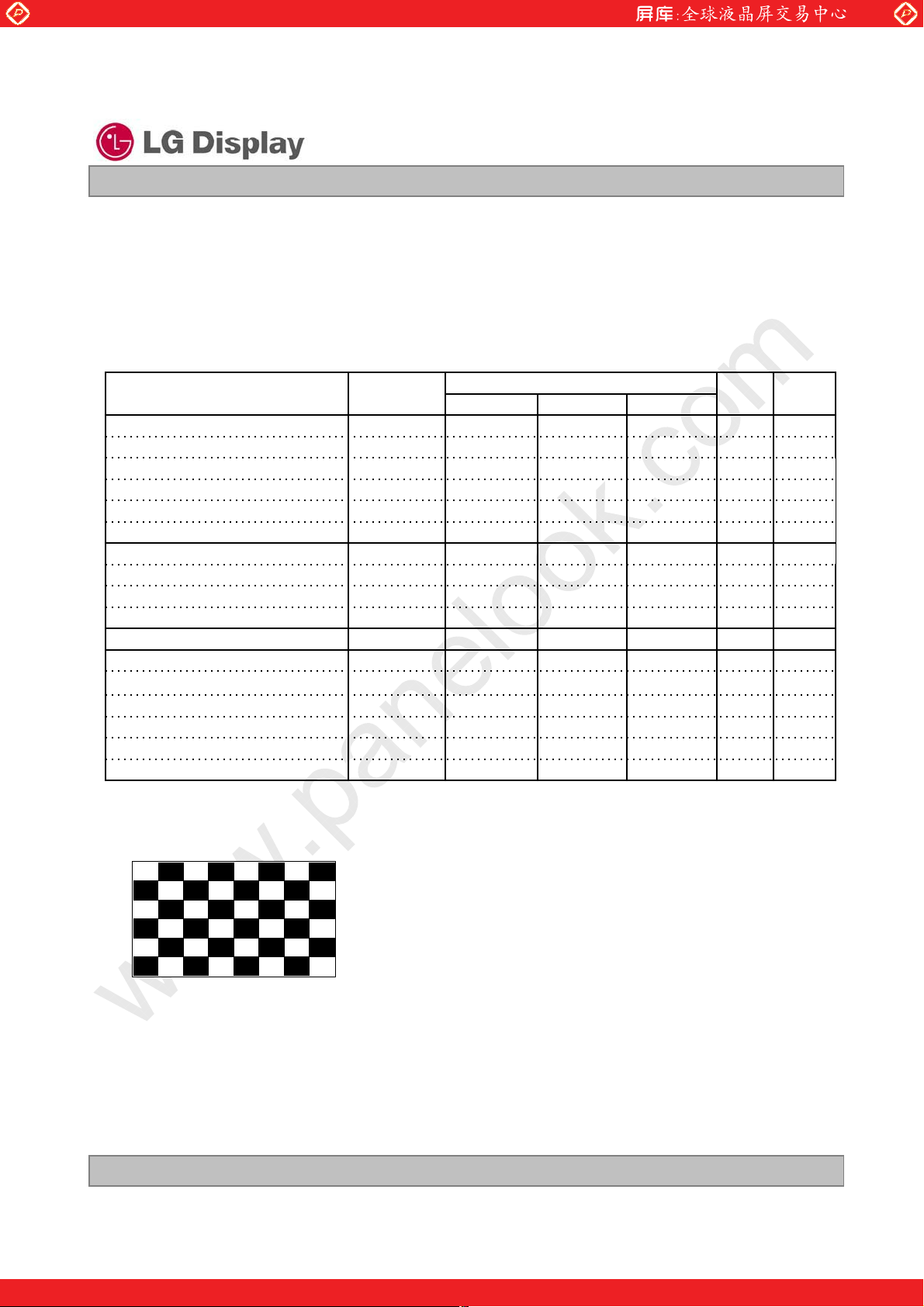
Ta= 25qC, Pattern : Mosaic(8 by 6),
Operating Time : 30 min
Lamp Operating Current : 6.0mA
{ Result Evaluation Criteria }
There should be no change which might affect the practical display function when the display quality
test is conducted under normal operating condition.
1)
After 30 minutes
Mosaic Pattern(8 by 6)
Half Gray
<Judgment Condition>
: Operating during 30 minutes with Mosaic Pattern(8 by 6), there is no Image Sticking
after 10 second with half gray pattern.
Ver. 1.0 Oct. 17, 2008
One step solution for LCD / PDP / OLED panel application: Datasheet, inventory and accessory!
26 / 33
www.panelook.com
Page 27

Global LCD Panel Exchange Center
7. International Standards
7-1. Safety
a) UL 60950-1:2003, First Edition, Underwriters Laboratories, Inc.,
Standard for Safety of Information Technology Equipment.
b) CAN/CSA C22.2, No. 60950-1-03 1
Standard for Safety of Information Technology Equipment.
c) EN 60950-1:2001, First Edition,
European Committee for Electrotechnical Standardization(CENELEC)
European Standard for Safety of Information Technology Equipment.
www.panelook.com
Liquid Crystal Display
Product Specification
st
Ed. April 1, 2003, Canadian Standards Association,
LP140WH1
7-2. EMC
a) ANSI C63.4 “Methods of Measurement of Radio-Noise Emissions from Low-Voltage Electrical and
Electrical Equipment in the Range of 9kHZ to 40GHz. “American National Standards Institute(ANSI),
1992
b) C.I.S.P.R “Limits and Methods of Measurement of Radio Interface Characteristics of Information
Technology Equipment.“ International Special Committee on Radio Interference.
c) EN 55022 “Limits and Methods of Measurement of Radio Interface Characteristics of Information
Technology Equipment.“ European Committee for Electrotechnical Standardization.(CENELEC), 1998
( Including A1: 2000 )
Ver. 1.0 Oct. 17, 2008
One step solution for LCD / PDP / OLED panel application: Datasheet, inventory and accessory!
27 / 33
www.panelook.com
Page 28

Global LCD Panel Exchange Center
8. Packing
8-1. Designation of Lot Mark
a) Lot Mark
ABCDEFGHI JKLM
A,B,C : SIZE(INCH) D : YEAR
E : MONTH F ~ M : SERIAL NO.
www.panelook.com
LP140WH1
Liquid Crystal Display
Product Specification
Note
1. YEAR
Year
Mark
200320022001
2. MONTH
Month
Mark
b) Location of Lot Mark
Serial No. is printed on the label. The label is attached to the backside of the LCD module.
This is subject to change without prior notice.
8-2. Packing Form
a) Package quantity in one box : 30 pcs
b) Box Size : 490 mm Ý 390 mm Ý 256 mm
321
200452005
4
Apr5May
4
2006720078200892009
6
Jun
Jul8Aug9Sep
6
7
2010
0
Oct
A
Nov
B
DecMarFebJan
C321
Ver. 1.0 Oct. 17, 2008
One step solution for LCD / PDP / OLED panel application: Datasheet, inventory and accessory!
28 / 33
www.panelook.com
Page 29

Global LCD Panel Exchange Center
9. PRECAUTIONS
Please pay attention to the followings when you use this TFT LCD module.
9-1. MOUNTING PRECAUTIONS
(1) You must mount a module using holes arranged in four corners or four sides.
(2) You should consider the mounting structure so that uneven force (ex. Twisted stress) is not applied to the
module. And the case on which a module is mounted should have sufficient strength so that external
force is not transmitted directly to the module.
(3) Please attach the surface transparent protective plate to the surface in order to protect the polarizer.
Transparent protective plate should have sufficient strength in order to the resist external force.
(4) You should adopt radiation structure to satisfy the temperature specification.
(5) Acetic acid type and chlorine type materials for the cover case are not desirable because the former
generates corrosive gas of attacking the polarizer at high temperature and the latter causes circuit break
by electro-chemical reaction.
(6) Do not touch, push or rub the exposed polarizers with glass, tweezers or anything harder than HB
pencil lead. And please do not rub with dust clothes with chemical treatment.
Do not touch the surface of polarizer for bare hand or greasy cloth.(Some cosmetics are detrimental
to the polarizer.)
(7) When the surface becomes dusty, please wipe gently with absorbent cotton or other soft materials like
chamois soaks with petroleum benzene. Normal-hexane is recommended for cleaning the adhesives
used to attach front / rear polarizers. Do not use acetone, toluene and alcohol because they cause
chemical damage to the polarizer.
(8) Wipe off saliva or water drops as soon as possible. Their long time contact with polarizer causes
deformations and color fading.
(9) Do not open the case because inside circuits do not have sufficient strength.
www.panelook.com
LP140WH1
Liquid Crystal Display
Product Specification
9-2. OPERATING PRECAUTIONS
(1) The spike noise causes the mis-operation of circuits. It should be lower than following voltage :
V=· 200mV(Over and under shoot voltage)
(2) Response time depends on the temperature.(In lower temperature, it becomes longer.)
(3) Brightness depends on the temperature. (In lower temperature, it becomes lower.)
And in lower temperature, response time(required time that brightness is stable after turned on) becomes
longer.
(4) Be careful for condensation at sudden temperature change. Condensation makes damage to polarizer or
electrical contacted parts. And after fading condensation, smear or spot will occur.
(5) When fixed patterns are displayed for a long time, remnant image is likely to occur.
(6) Module has high frequency circuits. Sufficient suppression to the electromagnetic interference shall be
done by system manufacturers. Grounding and shielding methods may be important to minimized the
interference.
Ver. 1.0 Oct. 17, 2008
29 / 33
One step solution for LCD / PDP / OLED panel application: Datasheet, inventory and accessory!
www.panelook.com
Page 30

Global LCD Panel Exchange Center
9-3. ELECTROSTATIC DISCHARGE CONTROL
Since a module is composed of electronic circuits, it is not strong to electrostatic discharge. Make certain that
treatment persons are connected to ground through wrist band etc. And don’t touch interface pin directly.
9-4. PRECAUTIONS FOR STRONG LIGHT EXPOSURE
Strong light exposure causes degradation of polarizer and color filter.
9-5. STORAGE
www.panelook.com
LP140WH1
Liquid Crystal Display
Product Specification
When storing modules as spares for a long time, the following precautions are necessary.
(1) Store them in a dark place. Do not expose the module to sunlight or fluorescent light. Keep the
temperature between 5qC and 35qC at normal humidity.
(2) The polarizer surface should not come in contact with any other object.
It is recommended that they be stored in the container in which they were shipped.
9-6. HANDLING PRECAUTIONS FOR PROTECTION FILM
(1) When the protection film is peeled off, static electricity is generated between the film and polarizer.
This should be peeled off slowly and carefully by people who are electrically grounded and with well
ion-blown equipment or in such a condition, etc.
(2) The protection film is attached to the polarizer with a small amount of glue. If some stress is applied
to rub the protection film against the polarizer during the time you peel off the film, the glue is apt to
remain on the polarizer.
Please carefully peel off the protection film without rubbing it against the polarizer.
(3) When the module with protection film attached is stored for a long time, sometimes there remains a
very small amount of glue still on the polarizer after the protection film is peeled off.
(4) You can remove the glue easily. When the glue remains on the polarizer surface or its vestige is
recognized, please wipe them off with absorbent cotton waste or other soft material like chamois
soaked with normal-hexane.
Ver. 1.0 Oct. 17, 2008
One step solution for LCD / PDP / OLED panel application: Datasheet, inventory and accessory!
30 / 33
www.panelook.com
Page 31

Global LCD Panel Exchange Center
ڣ ۀ ڼ ڿ ۀ ۍ
ڱ ۀ ۉ ڿ ۀ ۍڊ
ګ ۍۊڿې ھ ۏٻڤڟ
ڠ ڟ ڤڟ ٻڱ ۀۍێۄۊ ۉ ڊ
ڭ ۀۑۄێ ۄۊ ۉ
ڟ ۄێ ۋ ۇڼ ۔ٻ
ګ ڼۍڼۈ ۀۏۀۍ
ڞ ۊ ۇۊ ۍ
ڞ ۃ ڼ ۍڼ ھ ۏۀ ۍۄێۏۄھ
ڠ ێ ۏڼ ڽ ۇۄێ ۃ ۀ ڿ
گ ۄۈ ۄۉۂ ێ
ڮ ۏڼ ۉ ڿ ڼ ۍڿ
گۄۈ ۄۉۂ ٻڤڟ
APPENDIX A. Enhanced Extended Display Identification Data (EEDIDTM) 1/3
www.panelook.com
LP140WH1
Liquid Crystal Display
Product Specification
ڝ۔ۏۀپ ڝ۔ۏۀپ
ڃڿۀھۄۈڼۇڄ ڃڣڠڳڄ
ڡۄۀۇڿٻکڼۈ ۀٻڼۉڿٻڞ ۊۈ ۈ ۀۉۏێ
ڋ ڋڋ ڣۀڼڿۀۍ
ڌ ڋڌ ڣۀڼڿۀۍ
ڍ ڋڍ ڣۀڼڿۀۍ
ڎ ڋڎ ڣۀڼڿۀۍ
ڏ ڋڏ ڣۀڼڿۀۍ
ڐ ڋڐ ڣۀڼڿۀۍ
ڑ ڋڑ ڣۀڼڿۀۍ
ڒ ڋڒ ڣۀڼڿۀۍ
ړڋړڠڤڮڜٻۈڼۉېہڼھۏېۍۀۍٻھۊڿۀڃڎٻڞ ۃڼۍڼھۏۀۍٻڤڟڄٻژٻڧڢڟ
ڔ ڋڔ ڞ ۊۈ ۋۍۀێێۀڿٻڜڮ ڞ ڤڤ
ڌڋ ڋڜ ګۍۊڿېھۏٻھۊڿۀٻ
ڌ ڌ ڋڝ ڃڣ ۀ ۓ ڇٻڧ ڮ ڝ ٻہۄۍێ ۏڄ
ڌڍ ڋڞ ڧڞڟ ٻۈ ۊڿېۇۀٻڮۀۍۄڼۇٻکۊٻڈٻګۍۀہۀۍۍۀڿٻڽېۏٻڪ ۋ ۏۄۊۉڼۇٻٻڃ ڋٻۄہٻۉۊۏٻېێۀڿڄ
ڌڎ ڋڟ ڧڞ ڟ ٻۈ ۊڿېۇۀٻڮۀۍۄڼۇٻکۊٻڈٻګ ۍۀہۀۍۍۀڿٻڽېۏٻڪ ۋ ۏۄۊۉڼۇٻٻڃ ڋٻۄہٻۉۊۏٻېێۀڿڄ
ڌڏ ڋڠ ڧڞ ڟ ٻۈ ۊڿېۇۀٻڮۀۍۄڼۇٻکۊٻڈٻګ ۍۀہۀۍۍۀڿٻڽېۏٻڪ ۋ ۏۄۊۉڼۇٻٻڃ ڋٻۄہٻۉۊۏٻېێۀڿڄ
ڌڐ ڋڡ ڧڞ ڟ ٻۈ ۊڿېۇۀٻڮۀۍۄڼۇٻکۊٻڈٻګ ۍۀہۀۍۍۀڿٻڽېۏٻڪ ۋ ۏۄۊۉڼۇٻٻڃ ڋٻۄہٻۉۊۏٻېێۀڿڄ
ڌڑ ڌڋ ڲ ۀۀۆٻۊہٻڨ ڼۉېہڼھۏېۍۀ
ڌڒ ڌڌ ڴ ۀڼۍٻۊہٻڨ ڼۉېہڼھۏې ۍۀٻژٻڍڋڋړ
ڌړ ڌڍ ڠڟڤڟٻڮۏۍې ھ ۏېۍۀٻۑۀۍێۄۊ ۉ ٻپ ٻژ ٻڌ
ڌڔ ڌڎ ڠڟڤڟٻڭۀۑۄێۄۊۉٻپٻژٻڎ
ڍڋ ڌڏ ڱ ۄڿۀۊٻڤۉۋېۏٻڟ ۀ ہۄۉۄۏۄۊ ۉ ٻژ ٻڟ ۄۂۄۏڼۇٻڤڊګ ڇۉ ۊ ۉ ٻگ ڨ ڟ ڮ ٻڞ ڭ ڢ ڝ
ڍڌ ڌڐ ڨ ڼۓٻڣ ٻۄۈڼۂۀٻێۄەۀڃ༃ڄژڎڌھۈ
ڍڍ ڌڑ ڨ ڼۓٻڱ ٻۄۈڼۂۀٻێۄەۀڃ༃ڄژڌڒھۈ
ڍڎ ڌڒ ڟ ۄێۋۇڼ۔ٻۂڼۈ ۈ ڼٻژڍډڍ
ڍڏ ڌړ ڡۀڼۏېۍۀٻێېۋۋۊۍۏڃڟ ګ ڨ ڮ ڄٻژ ٻڜ ھ ۏۄۑۀٻۊ ہہڇٻڭ ڢ ڝ ٻڞ ۊ ۇۊۍ
ڍڐ ڌڔ ڭۀڿڊڢ ۍۀۀۉٻۇۊے ٻڝۄۏێٻ
ڍڑ ڌڜ ڝ ۇېۀڊڲ ۃۄۏۀٻڧۊے ٻڝ ۄۏێٻ
ڍ ڒ ڌڝ ڭ ۀ ڿ ٻڳ ٻٻٻٻٻٻژ ٻٻڋ ډڑ ڌ ړ
ڍ ړ ڌ ڞ ڭ ۀ ڿ ٻڴ ٻٻٻٻٻٻژ ٻٻڋ ډڎ ڐ ڐ
ڍ ڔ ڌڟ ڢ ۍۀ ۀ ۉ ٻڳ ٻٻٻژٻٻڋ ډڎ ڎ ڐ
ڎ ڋ ڌڠ ڢ ۍۀ ۀ ۉ ٻڴ ٻٻٻژٻٻڋ ډڐ ړ ڏ
ڎڌ ڌڡ ڝ ۇې ۀ ٻڳ ٻٻٻٻٻژ ٻٻڋ ډڌ ڐ ڋ
ڎڍ ڍڋ ڝ ۇې ۀ ٻڴ ٻٻٻٻٻژ ٻٻڋ ډڌ ڋ ڔ
ڎڎ ڍڌ ڲ ۃ ۄۏۀ ٻڳ ٻٻٻٻژٻڋډڎڌڎ ڐ ڋ
ڎڏ ڍڍ ڲ ۃ ۄۏۀ ٻڴ ٻٻٻٻژٻڋډڎڍڔ ڐ ڏ
ڎڐ ڍڎ ڠ ێۏڼڽۇۄێۃۀڿٻگۄۈۄۉۂٻڤٻژ ٻڋ ڋ ۃ ڃڤہٻۉۊۏٻېێۀڿڄ
ڎڑ ڍڏ ڠ ێۏڼڽۇۄێۃۀڿٻگۄۈۄۉۂٻڤڤٻژ ٻڋ ڋ ۃ ڃ ڤہٻۉ ۊ ۏٻېێۀڿڄ
ڎڒ ڍڐ ڨ ڼۉېہڼھۏېۍۀۍڂێٻگۄۈۄۉۂێٻژٻڋڋۃڃڤہٻۉ ۊ ۏٻېێۀڿڄ
ڎړ ڍڑ ڮ ۏڼۉڿڼۍڿٻگۄۈۄۉۂٻڤڿۀۉۏۄہۄھڼۏۄۊۉٻڌٻے ڼێٻۉۊۏٻېێۀڿ
ڎڔ ڍڒ ڮ ۏڼۉڿڼۍڿٻگۄۈۄۉۂٻڤڿۀۉۏۄہۄھڼۏۄۊۉٻڌٻے ڼێٻۉۊۏٻېێۀڿ
ڏڋ ڍړ ڮ ۏڼۉڿڼۍڿٻگۄۈۄۉۂٻڤڿۀۉۏۄہۄھڼۏۄۊۉٻڍٻے ڼێٻۉۊۏٻېێۀڿ
ڏڌ ڍڔ ڮ ۏڼۉڿڼۍڿٻگۄۈۄۉۂٻڤڿۀۉۏۄہۄھڼۏۄۊۉٻڍٻے ڼێٻۉۊۏٻېێۀڿ
ڏڍ ڍڜ ڮ ۏڼۉڿڼۍڿٻگۄۈۄۉۂٻڤڿۀۉۏۄہۄھڼۏۄۊۉٻڎٻے ڼێٻۉۊۏٻېێۀڿ
ڏڎ ڍڝ ڮ ۏڼۉڿڼۍڿٻگۄۈۄۉۂٻڤڿۀۉۏۄہۄھڼۏۄۊۉٻڎٻے ڼێٻۉۊۏٻېێۀڿ
ڏڏ ڍڞ ڮ ۏڼۉڿڼۍڿٻگۄۈۄۉۂٻڤڿۀۉۏۄہۄھڼۏۄۊۉٻڏٻے ڼێٻۉۊۏٻېێۀڿ
ڏڐ ڍڟ ڮ ۏڼۉڿڼۍڿٻگۄۈۄۉۂٻڤڿۀۉۏۄہۄھڼۏۄۊۉٻڏٻے ڼێٻۉۊۏٻېێۀڿ
ڏڑ ڍڠ ڮ ۏڼۉڿڼۍڿٻگۄۈۄۉۂٻڤڿۀۉۏۄہۄھڼۏۄۊۉٻڐٻے ڼێٻۉۊۏٻېێۀڿ
ڏڒ ڍڡ ڮ ۏڼۉڿڼۍڿٻگۄۈۄۉۂٻڤڿۀۉۏۄہۄھڼۏۄۊۉٻڐٻے ڼێٻۉۊۏٻېێۀڿ
ڏړ ڎڋ ڮ ۏڼۉڿڼۍڿٻگۄۈۄۉۂٻڤڿۀۉۏۄہۄھڼۏۄۊۉٻڑٻے ڼێٻۉۊۏٻېێۀڿ
ڏڔ ڎڌ ڮ ۏڼۉڿڼۍڿٻگۄۈۄۉۂٻڤڿۀۉۏۄہۄھڼۏۄۊۉٻڑٻے ڼێٻۉۊۏٻېێۀڿ
ڐڋ ڎڍ ڮ ۏڼۉڿڼۍڿٻگۄۈۄۉۂٻڤڿۀۉۏۄہۄھڼۏۄۊۉٻڒٻے ڼێٻۉۊۏٻېێۀڿ
ڐڌ ڎڎ ڮ ۏڼۉڿڼۍڿٻگۄۈۄۉۂٻڤڿۀۉۏۄہۄھڼۏۄۊۉٻڒٻے ڼێٻۉۊۏٻېێۀڿ
ڐڍ ڎڏ ڮ ۏڼۉڿڼۍڿٻگۄۈۄۉۂٻڤڿۀۉۏۄہۄھڼۏۄۊۉٻړٻے ڼێٻۉۊۏٻېێۀڿ
ڐڎ ڎڐ ڮ ۏڼۉڿڼۍڿٻگۄۈۄۉۂٻڤڿۀۉۏۄہۄھڼۏۄۊۉٻړٻے ڼێٻۉۊۏٻېێۀڿ
ڱڼۇېۀ
ڃڣڠڳڄ
ڋ ڋ ڋڋڋڋ ڋڋڋڋ
ڡ ڡ ڌڌڌڌ ڌڌڌڌ
ڡ ڡ ڌڌڌڌ ڌڌڌڌ
ڡ ڡ ڌڌڌڌ ڌڌڌڌ
ڡ ڡ ڌڌڌڌ ڌڌڌڌ
ڡ ڡ ڌڌڌڌ ڌڌڌڌ
ڡ ڡ ڌڌڌڌ ڌڌڌڌ
ڋ ڋ ڋڋڋڋ ڋڋڋڋ
ڎ ڋ ڋڋڌڌ ڋڋڋڋ
ڠ ڏ ڌڌڌڋ ڋڌڋڋ
ړ ڝ ڌڋڋڋ ڌڋڌڌ
ڋ ڌ ڋڋڋڋ ڋڋڋڌ
ڋ ڋ ڋڋڋڋ ڋڋڋڋ
ڋ ڋ ڋڋڋڋ ڋڋڋڋ
ڋ ڋ ڋڋڋڋ ڋڋڋڋ
ڋ ڋ ڋڋڋڋ ڋڋڋڋ
ڋ ڋ ڋڋڋڋ ڋڋڋڋ
ڌ ڍ ڋڋڋڌ ڋڋڌڋ
ڋ ڌ ڋڋڋڋ ڋڋڋڌ
ڋ ڎ ڋڋڋڋ ڋڋڌڌ
ړ ڋ ڌڋڋڋ ڋڋڋڋ
ڌ ڡ ڋڋڋڌ ڌڌڌڌ
ڌ ڌ ڋڋڋڌ ڋڋڋڌ
ڒ ړ ڋڌڌڌ ڌڋڋڋ
ڋ ڜ ڋڋڋڋ ڌڋڌڋ
ڏ ڠ ڋڌڋڋ ڌڌڌڋ
ړ ڐ ڌڋڋڋ ڋڌڋڌ
ڔ ڠ ڌڋڋڌ ڌڌڌڋ
ڐ ڝ ڋڌڋڌ ڌڋڌڌ
ڐ ڐ ڋڌڋڌ ڋڌڋڌ
ڔ ڐ ڌڋڋڌ ڋڌڋڌ
ڍ ڑ ڋڋڌڋ ڋڌڌڋ
ڌ ڞ ڋڋڋڌ ڌڌڋڋ
ڋ ڋ ڋڋڋڋ ڋڋڋڋ
ڋ ڋ ڋڋڋڋ ڋڋڋڋ
ڋ ڋ ڋڋڋڋ ڋڋڋڋ
ڋ ڌ ڋڋڋڋ ڋڋڋڌ
ڋ ڌ ڋڋڋڋ ڋڋڋڌ
ڋ ڌ ڋڋڋڋ ڋڋڋڌ
ڋ ڌ ڋڋڋڋ ڋڋڋڌ
ڋ ڌ ڋڋڋڋ ڋڋڋڌ
ڋ ڌ ڋڋڋڋ ڋڋڋڌ
ڋ ڌ ڋڋڋڋ ڋڋڋڌ
ڋ ڌ ڋڋڋڋ ڋڋڋڌ
ڋ ڌ ڋڋڋڋ ڋڋڋڌ
ڋ ڌ ڋڋڋڋ ڋڋڋڌ
ڋ ڌ ڋڋڋڋ ڋڋڋڌ
ڋ ڌ ڋڋڋڋ ڋڋڋڌ
ڋ ڌ ڋڋڋڋ ڋڋڋڌ
ڋ ڌ ڋڋڋڋ ڋڋڋڌ
ڋ ڌ ڋڋڋڋ ڋڋڋڌ
ڋ ڌ ڋڋڋڋ ڋڋڋڌ
ڱڼۇېۀ
ڃڽ ۄۉڼۍ۔ڄ
ڋڌڋڌ ڋڋڋڋ
ڋڌڋڌ ڋڌڋڋ
Ver. 1.0 Oct. 17, 2008
One step solution for LCD / PDP / OLED panel application: Datasheet, inventory and accessory!
31 / 33
www.panelook.com
Page 32

Global LCD Panel Exchange Center
گۄۈ ۄۉۂ
ڟ ۀ ێ ھ ۍۄۋۏۊ ۍ
پڌ
گۄۈ ۄۉۂ
ڟ ۀێ ھ ۍۄۋۏۄۊ ۉ
پڍ
گۄۈ ۄۉۂ
ڟ ۀێ ھ ۍۄۋۏۄۊ ۉ
پڎ
APPENDIX A. Enhanced Extended Display Identification Data (EEDIDTM) 2/3
www.panelook.com
LP140WH1
Liquid Crystal Display
Product Specification
ڝ۔ۏۀپ ڝ ۔ۏۀپ
ڃڿ ۀ ھ ۄۈڼۇڄ ڃڣڠڳڄ
ڐڏ ڎڑ ڌڎڑڑڳڒڑړٻڛ ڑڋ༨ٻۈ ۊڿۀٻۋ ۄۓۀۇٻھ ۇۊھ ۆٻڃڧڮ ڝ ڄٻٻٻٻژڙٻٻڒڍډڎڨ ڣ ە ڎ ڠ ڋڋڌڌ ڌڌڌڋ
ڐڐ ڎڒ ڃڮ ۏۊۍۀڿٻڧڮڝ ٻہۄۍێ ۏڄ ڌ ڞ ڋڋڋڌ ڌڌڋڋ
ڐڑ ڎړ ڣۊۍۄەۊۉۏڼۇٻڜ ھ ۏۄۑۀٻژٻڌڎڑڑٻۋ ۄۓۀۇێ ٻٻٻٻٻٻٻٻٻٻٻٻٻڃۇۊے ۀۍٻړڽۄۏێ ڄ ڐ ڑ ڋڌڋڌ ڋڌڌڋ
ڐڒ ڎڔ ڣۊۍۄەۊۉۏڼۇٻڝ ۇڼۉۆۄۉ ۂٻژٻڌڑڋٻۋ ۄۓۀۇێ ٻٻٻٻٻٻٻٻٻٻٻڃ ۇۊے ۀۍٻړڽۄۏێ ڄ ڜ ڋ ڌڋڌڋ ڋڋڋڋ
ڐړ ڎڜ ڣ ۊ ۍۄەۊۉۏڼۇٻڜ ھ ۏۄۑ ۀ ٻڕٻڣ ۊ ۍۄەۊۉۏڼۇٻڝ ۇڼۉۆۄۉۂٻٻڃېۋۋۀۍٻڏڕڏڽۄۏێڄ ڐ ڋ ڋڌڋڌ ڋڋڋڋ
ڐڔ ڎڝ ڱ ۀ ۍۏۄھڼۇٻڜ ۑ ۏۄۑۀٻژٻڒڑړٻۇۄۉ ۀ ێ ٻٻٻٻٻٻٻٻٻٻٻٻٻٻٻٻٻٻٻٻڃۇۊے ۀۍٻړڽۄۏێ ڄ ڋ ڋ ڋڋڋڋ ڋڋڋڋ
ڑڋ ڎڞ ڱ ۀ ۍۏۄھڼۇٻڝ ۇڼۉۆۄۉ ۂ ٻژٻڍڍٻۇۄۉ ۀ ێ ٻٻٻٻٻٻٻٻٻٻٻٻٻٻٻٻٻٻڃ ۇۊے ۀۍٻړڽۄۏێ ڄ ڌ ڑ ڋڋڋڌ ڋڌڌڋ
ڑڌ ڎڟ ڱ ۀ ۍۏۄھڼۇٻڜ ھ ۏۄۑ ۀ ٻڕٻڱ ۀ ۍۏۄھڼۇٻڝ ۇڼۉۆۄۉ ۂ ٻٻٻٻٻٻٻٻٻڃ ې ۋ ۋ ۀ ۍٻڏ ڕڏ ڽ ۄۏێڄ ڎ ڋ ڋڋڌڌ ڋڋڋڋ گ
ڑڍ ڎڠ ڣ ۊ ۍۄەۊۉۏڼۇٻڮ ۔ ۉ ھ ډٻڪ ہہێۀۏٻژ ٻڏ ړ ٻۋ ۄۓۀۇێ ڎ ڋ ڋڋڌڌ ڋڋڋڋ ڟ
ڑڎ ڎڡ ڣ ۊ ۍۄەۊۉۏڼۇٻڮ ۔ ۉ ھ ٻګ ې ۇێۀٻڲ ۄڿۏۃ ٻژٻڎڍٻۋۄۓۀۇێڍڋ
ڑڏ ڏڋ ڱۀۍۏۄھڼۇٻڮ ۔ۉھٻڪ ہہێۀۏٻژ ٻڎ ٻۇۄۉۀێٻڕٻڮ۔ۉھٻڲ ۄڿۏۃ ٻژٻڐٻۇۄۉۀ ێ ڎ ڐ ڋڋڌڌ ڋڌڋڌ
ڑڐ ڏڌ ڣۊۍۄەۊۉۏڼۇٻڱ ۀ ۍۏۄھڼۇٻٻڮ ۔ ۉ ھ ٻڪ ہہێۀۏڊڲ ۄڿۏۃٻېۋۋۀۍٻڍڽۄۏێ ٻژٻڋ ڋ ڋ ڋڋڋڋ ڋڋڋڋ
ڑڑ ڏڍ ڣۊۍۄەۊۉۏڼۇٻڤۈڼۂۀٻڮۄەۀ ٻژٻڎڋڔډڎڔڔۈ ۈ ڃڎڋڔڄ ڎ ڐ ڋڋڌڌ ڋڌڋڌ
ڑڒ ڏڎ ڱۀۍۏۄھڼۇٻڤۈڼۂۀٻڮۄەۀٻژٻڌڒڎډڔڐڍۈ ۈ ڃڌڒڎڄ ڜ ڠ ڌڋڌڋ ڌڌڌڋ
ڑړ ڏڏ ڣۊۍۄەۊۉۏڼۇٻځ ٻڱ ۀ ۍۏۄھڼۇٻڤۈ ڼۂۀٻڮ ۄەۀ ڌ ڋ ڋڋڋڌ ڋڋڋڋ
ڑڔ ڏڐ ڣۊۍۄەۊۉۏڼۇٻڝ ۊ ۍڿ ۀ ۍٻژٻڋ ڋ ڋ ڋڋڋڋ ڋڋڋڋ
ڒڋ ڏڑ ڱۀۍۏۄھڼۇٻڝۊ ۍڿۀ ۍٻژٻڋ ڋ ڋ ڋڋڋڋ ڋڋڋڋ
ڒڌ ڏڒ
ڒڍ ڏړ ڟۀۏڼۄۇۀڿٻگۄۈۄۉۂٻڟ ۀێھۍۄۋۏۊۍٻپڍ ڋ ڋ ڋڋڋڋ ڋڋڋڋ
ڒڎ ڏڔ ڋ ڋ ڋڋڋڋ ڋڋڋڋ
ڒڏ ڏڜ ڋ ڋ ڋڋڋڋ ڋڋڋڋ
ڒڐ ڏڝ ڋ ڋ ڋڋڋڋ ڋڋڋڋ
ڒڑ ڏڞ ڋ ڋ ڋڋڋڋ ڋڋڋڋ
ڒڒ ڏڟ ڋ ڋ ڋڋڋڋ ڋڋڋڋ
ڒړ ڏڠ ڋ ڋ ڋڋڋڋ ڋڋڋڋ
ڒڔ ڏڡ ڋ ڋ ڋڋڋڋ ڋڋڋڋ گ
ړڋ ڐڋ ڋ ڋ ڋڋڋڋ ڋڋڋڋ ڟ
ړڌ ڐڌ ڋ ڋ ڋڋڋڋ ڋڋڋڋ پ
ړڍ ڐڍ ڋ ڋ ڋڋڋڋ ڋڋڋڋ
ړڎ ڐڎ ڋ ڋ ڋڋڋڋ ڋڋڋڋ
ړڏ ڐڏ ڋ ڋ ڋڋڋڋ ڋڋڋڋ
ړڐ ڐڐ ڋ ڋ ڋڋڋڋ ڋڋڋڋ
ړڑ ڐڑ ڋ ڋ ڋڋڋڋ ڋڋڋڋ
ړڒ ڐڒ ڋ ڋ ڋڋڋڋ ڋڋڋڋ
ړړ ڐړ ڋ ڋ ڋڋڋڋ ڋڋڋڋ
ړڔ ڐڔ ڋ ڋ ڋڋڋڋ ڋڋڋڋ
ڔڋ ڐڜ ڟ ۀ ۏڼۄۇۀڿٻگۄۈۄۉۂٻڟ ۀێھۍۄۋۏۊۍٻپ ڎ ڋ ڋ ڋڋڋڋ ڋڋڋڋ
ڔڌ ڐڝ ڋ ڋ ڋڋڋڋ ڋڋڋڋ
ڔڍ ڐڞ ڋ ڋ ڋڋڋڋ ڋڋڋڋ
ڔڎ ڐڟ ڡ ڠ ڌڌڌڌ ڌڌڌڋ
ڔڏ ڐڠ ڋ ڋ ڋڋڋڋ ڋڋڋڋ
ڔڐ ڐڡ ڧ ڏ ڞ ڋڌڋڋ ڌڌڋڋ
ڔڑ ڑڋ ڢ ڏ ڒ ڋڌڋڋ ڋڌڌڌ
ڔڒ ڑڌ ڍ ڋ ڋڋڌڋ ڋڋڋڋ گ
ڔړ ڑڍ ڟ ڏ ڏ ڋڌڋڋ ڋڌڋڋ ڟ
ڔڔ ڑڎ ۄ ڑ ڔ ڋڌڌڋ ڌڋڋڌ پ
ڌڋڋ ڑڏ ێ ڒ ڎ ڋڌڌڌ ڋڋڌڌ
ڌڋڌ ڑڐ ۋ ڒ ڋ ڋڌڌڌ ڋڋڋڋ
ڌڋڍ ڑڑ ۇ ڑ ڞ ڋڌڌڋ ڌڌڋڋ
ڌڋڎ ڑڒ ڼ ڑ ڌ ڋڌڌڋ ڋڋڋڌ
ڌڋڏ ڑړ ۔ ڒ ڔ ڋڌڌڌ ڌڋڋڌ
ڌڋڐ ڑڔ ڧڡ ڋ ڜ ڋڋڋڋ ڌڋڌڋ
ڌڋڑ ڑڜ ڍ ڋ ڋڋڌڋ ڋڋڋڋ
ڌڋڒ ڑڝ ڍ ڋ ڋڋڌڋ ڋڋڋڋ
کۊۉڈۄۉۏۀۍۇڼھۀڿڇک ۊۍۈ ڼۇٻڿ ۄێۋۇڼ۔ڇۉۊٻێۏۀۍۀۊڇڟ ۄۂۄۏڼ ۇٻێۀۋڼۍڼۏۀٻێ۔ۉھڇڣڊڱٻۋۊۇٻۉۀۂڼۏۄۑۀ ێ
ڡۄۀۇڿٻک ڼۈ ۀٻڼۉڿٻڞ ۊۈ ۈ ۀۉۏێ
ڱڼۇېۀ
ڃڣڠڳڄ
ڌ ڔ ڋڋڋڌ ڌڋڋڌ
ڱڼۇېۀ
ڃڽ ۄۉڼۍ۔ڄ
ڋڋڌڋ ڋڋڋڋ پ
Ver. 1.0 Oct. 17, 2008
One step solution for LCD / PDP / OLED panel application: Datasheet, inventory and accessory!
32 / 33
www.panelook.com
Page 33

Global LCD Panel Exchange Center
گۄۈ ۄۉۂ
ڟ ۀ ێ ھ ۍۄۋ ۏۄۊ ۉ
پ ڏ
ڠ ۓۏۀ ۉێ ۄۊ ۉٻڡۇڼ ۂ
ڠ ڞ
ڞ ۃۀ ھۆێ ېۈ
APPENDIX A. Enhanced Extended Display Identification Data (EEDIDTM) 3/3
www.panelook.com
LP140WH1
Liquid Crystal Display
Product Specification
ڝ۔ۏۀپ ڝ ۔ۏۀپ
ڃڿ ۀ ھ ۄۈڼۇڄ ڃڣڠڳڄ
ڌڋړ ڑڞ ڟ ۀۏڼۄۇۀڿٻگۄۈۄۉۂٻڟۀێھۍۄۋۏۊ ۍٻپ ڏ ڋ ڋ ڋڋڋڋ ڋڋڋڋ
ڌڋڔ ڑڟ ڋ ڋ ڋڋڋڋ ڋڋڋڋ
ڌڌڋ ڑڠ ڋ ڋ ڋڋڋڋ ڋڋڋڋ
ڌڌڌ ڑڡ ڡ ڠ ڌڌڌڌ ڌڌڌڋ
ڌڌڍ ڒڋ ڋ ڋ ڋڋڋڋ ڋڋڋڋ
ڌڌڎ ڒڌ ڧ ڏ ڞ ڋڌڋڋ ڌڌڋڋ
ڌڌڏ ڒڍ ګ ڐ ڋ ڋڌڋڌ ڋڋڋڋ
ڌڌڐ ڒڎ ڌ ڎ ڌ ڋڋڌڌ ڋڋڋڌ گ
ڌڌڑ ڒڏ ڏ ڎ ڏ ڋڋڌڌ ڋڌڋڋ ڟ
ڌڌڒ ڒڐ ڋ ڎ ڋ ڋڋڌڌ ڋڋڋڋ پ
ڌڌړ ڒڑ ڲ ڐ ڒ ڋڌڋڌ ڋڌڌڌ
ڌڌڔ ڒڒ ڣ ڏ ړ ڋڌڋڋ ڌڋڋڋ
ڌڍڋ ڒړ ڌ ڎ ڌ ڋڋڌڌ ڋڋڋڌ
ڌڍڌ ڒڔ ڈ ڍ ڟ ڋڋڌڋ ڌڌڋڌ
ڌڍڍ ڒڜ گ ڐ ڏ ڋڌڋڌ ڋڌڋڋ
ڌڍڎ ڒڝ ڧ ڏ ڞ ڋڌڋڋ ڌڌڋڋ
ڌڍڏ ڒڞ ڜ ڏ ڌ ڋڌڋڋ ڋڋڋڌ
ڌڍڐ ڒڟ ڌ ڎ ڌ ڋڋڌڌ ڋڋڋڌ
ڌڍڑ ڒڠ ڠ ۓۏۀۉێۄۊۉٻہۇڼ ۂ ٻژٻڋڋ ڋ ڋ ڋڋڋڋ ڋڋڋڋ ڠ
ڌڍڒ ڒڡ ڞ ۃۀھۆێېۈ ڠ
ڡۄۀۇڿٻک ڼۈ ۀٻڼۉڿٻڞ ۊۈ ۈ ۀۉۏێ
ڱڼۇېۀ
ڃڣڠڳڄ
ڱڼۇېۀ
ڃڽ ۄۉڼۍ۔ڄ
ڌڌڌڋ ڌڌڋڋ ڞ
Ver. 1.0 Oct. 17, 2008
One step solution for LCD / PDP / OLED panel application: Datasheet, inventory and accessory!
33 / 33
www.panelook.com
 Loading...