

Page 1
LC550EUF
Product Specification
SPECIFICATION
FOR
APPROVAL
)
(
(
Preliminary Specification
●
)
Final Specification
Title 55.0” WUXGA TFT LCD
BUYER GENERAL
MODEL
APPROVED BY
/
/
/
SIGNATURE
DATE
SUPPLIER L&T Display Technology., Ltd.
*MODEL LC550EUF
SUFFIX LDC1 (RoHS Verified)
*When you obtain standard approval,
please use the above model name without suffix
APPROVED BY
/ Team Leader
REVIEWED BY
Y. H Choi / Project Leader
PREPARED BY
/ Engineer
SIGNATURE
DATE
Please return 1 copy for your confirmation with
your signature and comments.
Ver. 0.1
R&D Dept.
L&T Display Technology., Ltd
Page 2
Product Specification
CONTENTS
LC550EUF
Number
1
2
3
3-1
3-2
3-3
3-4
3-5
3-6
4
5
ITEM
COVER 1
CONTENTS
RECORD OF REVISIONS
GENERAL DESCRIPTION
ABSOLUTE MAXIMUM RATINGS
ELECTRICAL SPECIFICATIONS
ELECTRICAL CHARACTERISTICS
INTERFACE CONNECTIONS
SIGNAL TIMING SPECIFICATIONS
SIGNAL TIMING WAVEFORMS
COLOR DATA REFERENCE
POWER SEQUENCE
OPTICAL SPECIFICATIONS
MECHANICAL CHARACTERISTICS
Page
11
12
15
16
17
23
2
3
4
5
6
6
8
6
6-1
7
7-1
7-2
7-3
7-4
7-5
7-6
7-7 OPERATING CONDIDITON GUIDE
Ver. 0.1
INTERNATIONAL STANDARDS
ENVIRONMENT
PRECAUTIONS
MOUNTING PRECAUTIONS
OPERATING PRECAUTIONS
ELECTROSTATIC DISCHARGE CONTROL
PRECAUTIONS FOR STRONG LIGHT EXPOSURE
STORAGE
HANDLING PRECAUTIONS FOR PROTECTION FILM
26
26
27
27
27
28
28
28
28
28
1 /38
Page 3
Product Specification
RECORD OF REVISIONS
Revision No. Revision Date Page Description
1.0 Jun, 07, 2011 - Preliminary Specification
LC550EUF
Ver. 0.1
2 /38
Page 4
LC550EUF
Product Specification
1. General Description
The LC550EUF is a Color Active Matrix Liquid Crystal Display with an integral Light Emitting Diode (LED)
backlight system. The matrix employs a-Si Thin Film Transistor as the active element.
It is a transmissive type display operating in the normally black mode. It has a 54.64 inch diagonally measured
active display area with WUXGA resolution (1080 vertical by 1920 horizontal pixel array).
Each pixel is divided into Red, Green and Blue sub-pixels or dots which are arranged in vertical stripes.
Gray scale or the luminance of the sub-pixel color is determined with a 8-bit gray scale signal for each dot.
Therefore, it can present a palette of more than 16.7M(true) colors.
It is intended to support LCD TV, PCTV where high brightness, super wide viewing angle, high color gamut,
high color depth and fast response time are important.
Mini-LVDS(RGB)
Control
Signals
Power Signals
Source Driver Circuit
S1 S1920
G1
TFT - LCD Panel
(1920 × RGB × 1080 pixels)
G1080
LVDS
2Port
LVDS
2Port
LVDS
Select
Bit
Select
+12.0V
CN2
(41pin)
CN1
(51pin)
LVDS 3,4
LVDS 1,2
Option
signal
I2C
EEPROM
SCL
SDA
Timing Controller
LVDS Rx + DGA + ODC
Integrated
Power Circuit
Block
LED Anode
LED Cathode
CN1 (12pin)
CN2 (13pin)
V : 8Block
Local Dimming : 16 Block
General Features
Active Screen Size
Outline Dimension
Pixel Pitch 0.630 mm x 0.630 mm x RGB
Pixel Format 1920 horiz. by 1080 vert. Pixels, RGB stripe arrangement
Color Depth 10Bit(D), 1.06 Billion colors
Luminance, White 400 cd/m2 (Center 1point ,Typ.)
Viewing Angle (CR>10) Viewing angle free ( R/L 178 (Min.), U/D 178 (Min.))
Power Consumption Total 122.5W (Typ.) [Logic= 6.1W, LED Driver=116.4W @ with LED Driver]
Weight 14.5 Kg (TBD.)
Display Mode Transmissive mode, Normally black
Surface Treatment Hard coating(2H), Anti-glare treatment of the front polarizer (Haze 10%)
54.64 inch (1387.80mm) diagonal
1253.6(H) × 725.0(V) X 21.0(B)/10.8 mm(D) (Typ.)
V : 8Block
Ver. 0.1
3 /38
Page 5
LC550EUF
Product Specification
2. Absolute Maximum Ratings
The following items are maximum values which, if exceeded, may cause faulty operation or permanent damage
to the LCD module.
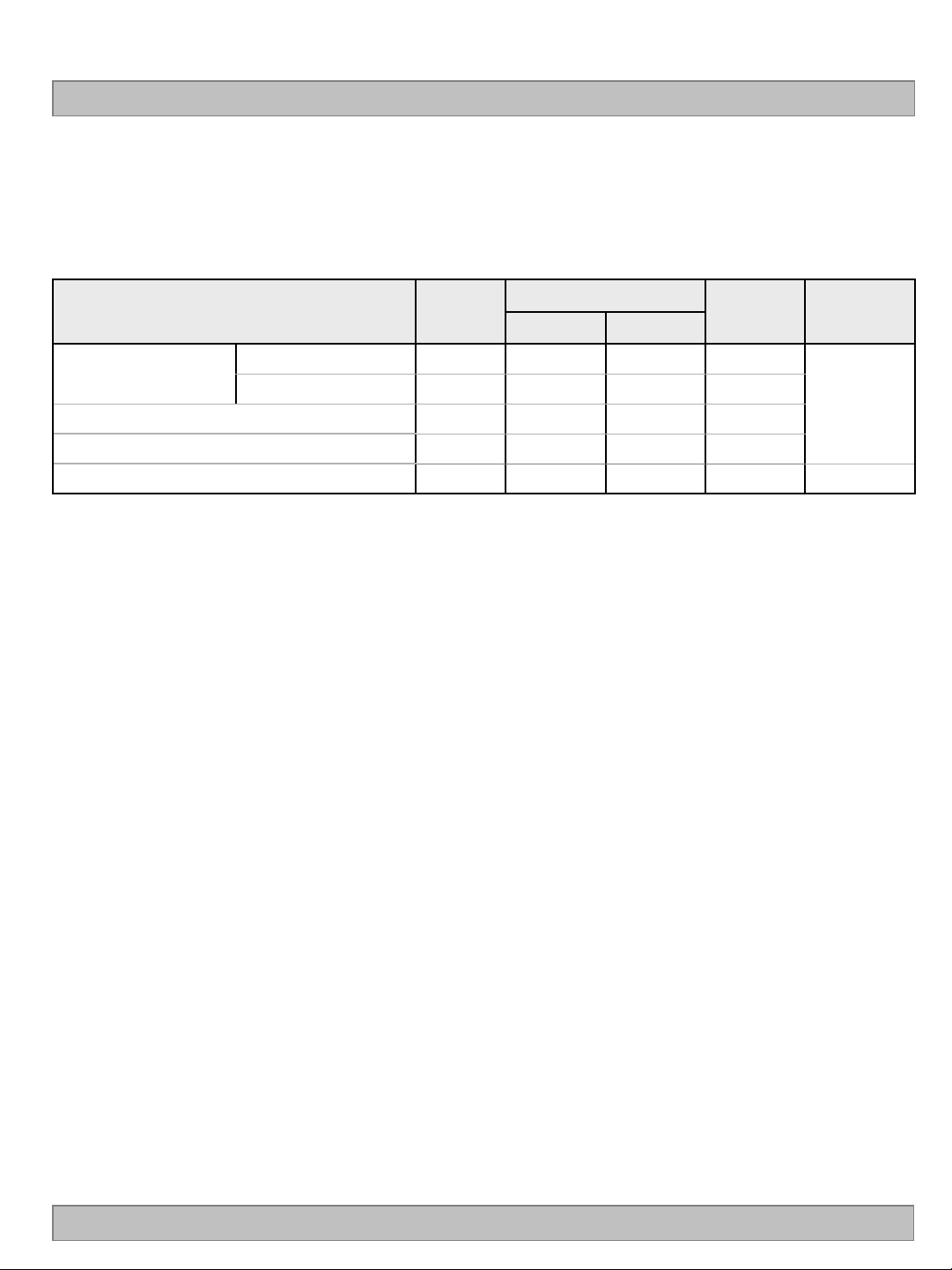
Table 1. ABSOLUTE MAXIMUM RATINGS
Parameter Symbol
Unit Note
Min Max
Value
Power Input Voltage
LED Input Voltage VF - +180.0 VDC
T-Con Option Selection Voltage VLOGIC
Panel Front Temperature TSUR
Note
1. Ambient temperature condition (Ta = 25 2 °C )
LCD Circuit VLCD -0.3 +14.0 VDC
Driver VBL -0.3 + 27.0 VDC
-0.3 +4.0 VDC
- +68
°C
1
2
2. The maximum operating temperatures is based on the test condition that the surface temperature
of display area is less than or equal to 68°C with LCD module alone in a temperature controlled chamber.
Thermal management should be considered in final product design to prevent the surface temperature of
display area from being over 68℃. The range of operating temperature may be degraded in case of
improper thermal management in final product design.
Ver. 0.1
4 /38
Page 6
LC550EUF
Product Specification
3. Electrical Specifications
3-1. Electrical Characteristics
It requires two power inputs. One is employed to power for the LCD circuit. The other Is used for the LED
backlight and LED Driver circuit.
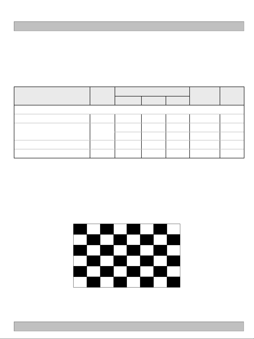
Table 2. ELECTRICAL CHARACTERISTICS
Parameter Symbol
Unit Note
Min Typ Max
Value
Circuit :
Power Input Voltage VLCD 10.8 12.0 13.2 VDC
Power Input Current ILCD
Power Consumption PLCD - 6.1 8.0 Watt 1
Rush current IRUSH - - 5.0 A 3
Note
1. The specified current and power consumption are under the V
- 510 663 mA 1
- 765 995 mA 2
=12.0V, Ta=25 2°C, fV=120Hz
LCD
condition, and mosaic pattern(8 x 6) is displayed and fV is the frame frequency.
2. The current is specified at the maximum current pattern.
3. The duration of rush current is about 2ms and rising time of power input is 0.5ms (min.).
White : 1023 Gray
Black : 0 Gray
Ver. 0.1
Mosaic Pattern(8 x 6)
5 /38
Page 7
Product Specification
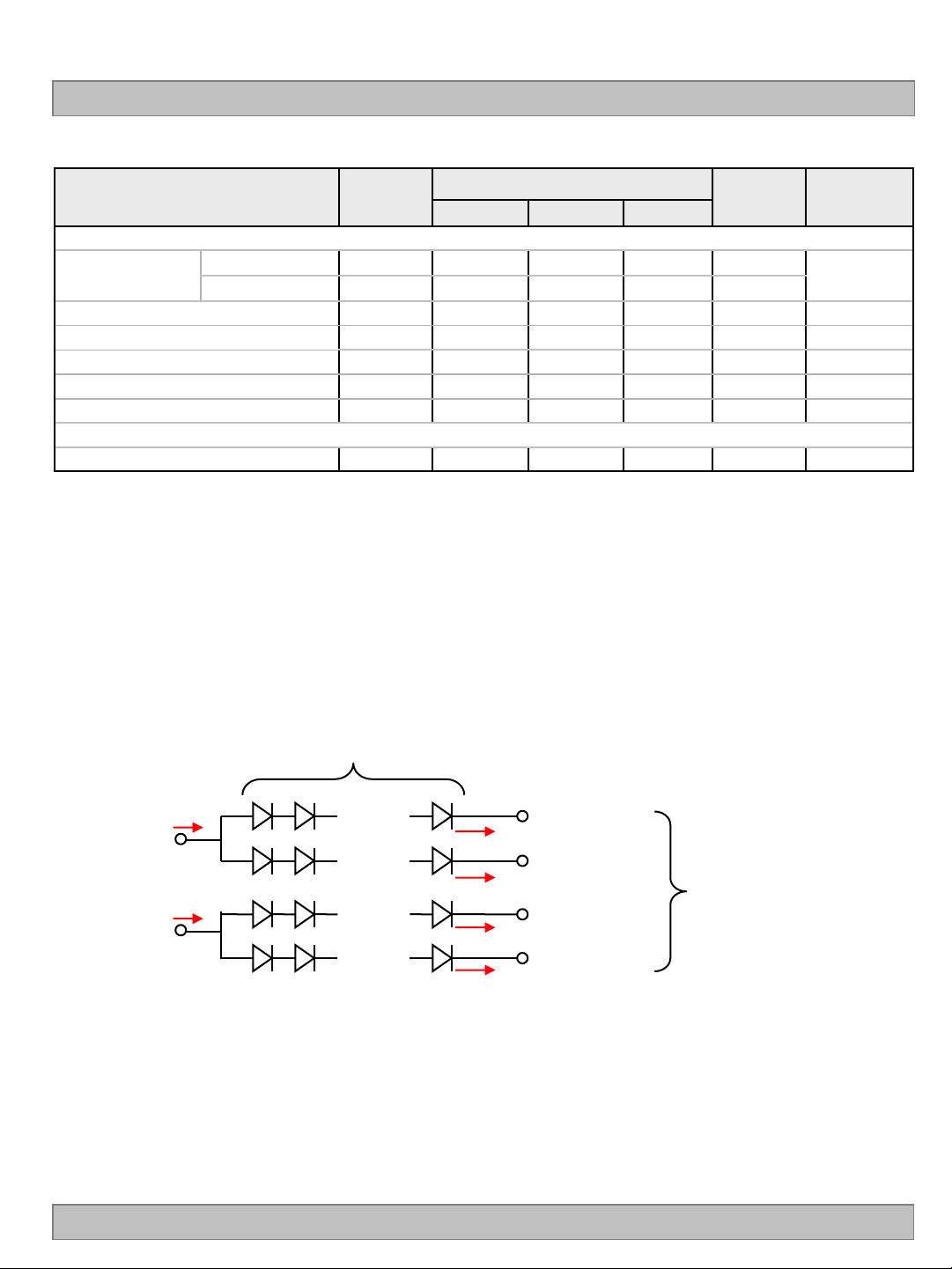
Table 3. ELECTRICAL CHARACTERISTICS (Continue)
LC550EUF
Parameter Symbol
Values
Unit Note
Min Typ Max
Backlight Assembly :
Forward Current
(one array)
Forward Voltage V
Forward Voltage Variation
Power Consumption P
Anode I
Cathode I
F (anode)
F (cathode)
F
△V
F
BL
Burst Dimming Duty On duty
Burst Dimming Frequency 1/T
400
95 100 105
58.0 64.0 70.0
92.8 102.4 112.0
10 - 100
95 182
1.7
mAdc
mAdc
Vdc
Vdc
W 6
%
Hz 8
LED Array : (APPENDIX-V)
Life Time 30,000 50,000 Hrs 7
The design of the LED driver must have specifications for the LED array in LCD Assembly.
Notes :
The electrical characteristics of LED driver are based on Constant Current driving type.
The performance of the LED in LCM, for example life time or brightness, is extremely influenced by the
characteristics of the LED Driver. So, all the parameters of an LED driver should be carefully designed.
When you design or order the LED driver, please make sure unwanted lighting caused by the mismatch of the
LED and the driver (no lighting, flicker, etc) has never been occurred. When you confirm it, the LCD–
Assembly should be operated in the same condition as installed in your instrument.
1. Electrical characteristics are based on LED Array specification.
2. Specified values are defined for a Backlight Assembly. (2 LED arrays/LCM)
3. Each LED array has 2 anode terminals and 8 cathode terminals.
The forward current(IF) of the anode terminals are 400mA and it supplies 100mA into 4
Strings, respectively
1string(10 LED PKG)
Anode#1
Anode#2
400mA
400mA
° ° °
° ° °
° ° °
Cathode #1
100mA
Cathode #4
100mA
1 Array (8 Strings)
° ° °
° ° °
° ° °
100mA
100mA
Cathode #5
Cathode #8
4. The forward voltage(VF) of LED array depends on ambient temperature (Appendix-VII)
5. ΔV
means Max VF-Min VF in one Backlight. So VF variation in a Backlight isn’t over Max. 1.7V
F
6. Maximum level of power consumption is measured at initial turn on.
Typical level of power consumption is measured after 1hrs aging at 25 2°C.
7. The life time(MTTF) is determined as the time at which brightness of the LED is 50% compared to that of
initial value at the typical LED current on condition of continuous operating at 25 2°C, based on duty 100%.
8. The reference method of burst dimming duty ratio.
It is recommended to use synchronous V-sync frequency to prevent waterfall
(Vsync x 1 =Burst Frequency)
Though PWM frequency is over 182Hz (max252Hz), function of backlight is not affected.
Ver. 0.1
±5%
2, 3
4
5
6 /38
Page 8
LC550EUF
Product Specification
3-2. Interface Connections
This LCD module employs two kinds of interface connection, 51-pin connector and 41-pin connector are used
for the module electronics and 12-pin,13-pin connectors are used for the integral backlight system.
3-2-1. LCD Module
- LCD Connector(CN1): FI-RE51S-HF(manufactured by JAE)
Refer to below and next Page table
- Mating Connector : FI-R51HL(JAE) or compatible
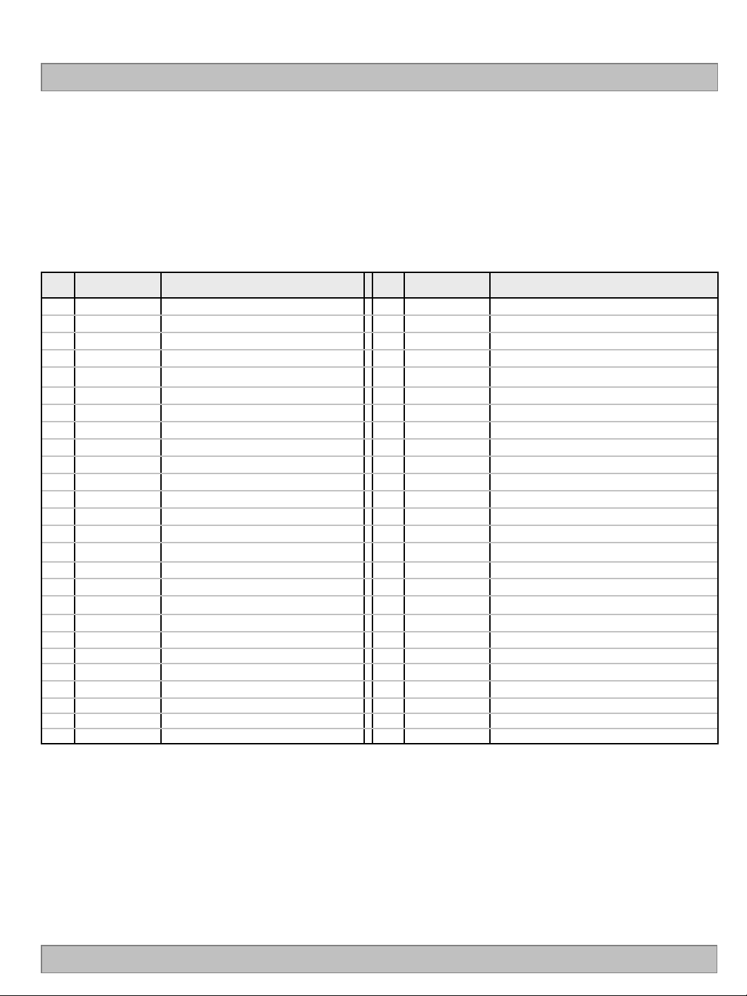
Table 4-1. MODULE CONNECTOR(CN1) PIN CONFIGURATION
No Symbol Description No Symbol Description
NC or GND
1
2
3
4
5
6
7
8
9
10
11 GND
12 R1AN
13 R1AP
14 R1BN
15
16 R1CN
17 R1CP
18 GND
19 R1CLKN
20
21 GND
22 R1DN
23 R1DP
24 R1EN
25 R1EP
26
NC
NC
NC
NC
NC
LVDS Select
NC
NC
NC No Connection (Note 4)
R1BP
R1CLKP
NC or GND
No Connection (Note 4)
No Connection (Note 4)
No Connection (Note 4)
No Connection (Note 4)
No Connection (Note 4)
No Connection (Note 4)
‘H’ =JEIDA , ‘L’ or NC = VESA
No Connection (Note 4)
No Connection (Note 4)
Ground
FIRST LVDS Receiver Signal (A-)
FIRST LVDS Receiver Signal (A+)
FIRST LVDS Receiver Signal (B-)
FIRST LVDS Receiver Signal (B+)
FIRST LVDS Receiver Signal (C-)
FIRST LVDS Receiver Signal (C+)
Ground
FIRST LVDS Receiver Clock Signal(-)
FIRST LVDS Receiver Clock Signal(+)
Ground
FIRST LVDS Receiver Signal (D-)
FIRST LVDS Receiver Signal (D+)
FIRST LVDS Receiver Signal (E-)
FIRST LVDS Receiver Signal (E+)
No Connection or Ground
27
Bit Select
28
29
30
31
32
33
34
35
36
37
38
39
40 R2EN
41 R2EP
42
43
44
45
46
47
48
49
50
51
- - -
R2AN
R2AP
R2BN
R2BP
R2CN
R2CP
GND
R2CLKN
R2CLKP
GND
R2DN
R2DP
NC or GND
NC or GND
GND Ground
GND Ground
GND Ground
NC No connection
VLCD Power Supply +12.0V
VLCD Power Supply +12.0V
VLCD Power Supply +12.0V
VLCD Power Supply +12.0V
‘H’ or NC= 10bit(D) , ‘L’ = 8bit
SECOND LVDS Receiver Signal (A-)
SECOND LVDS Receiver Signal (A+)
SECOND LVDS Receiver Signal (B-)
SECOND LVDS Receiver Signal (B+)
SECOND LVDS Receiver Signal (C-)
SECOND LVDS Receiver Signal (C+)
Ground
SECOND LVDS Receiver Clock Signal(-)
SECOND LVDS Receiver Clock Signal(+)
Ground
SECOND LVDS Receiver Signal (D-)
SECOND LVDS Receiver Signal (D+)
SECOND LVDS Receiver Signal (E-)
SECOND LVDS Receiver Signal (E+)
No Connection or Ground
No Connection or Ground
Note
Ver. 0.1
1. All GND(ground) pins should be connected together to the LCD module’s metal frame.
2. All VLCD (power input) pins should be connected together.
3. All Input levels of LVDS signals are based on the EIA 644 Standard.
4. #1~#6 & #8~#10 NC (No Connection): These pins are used only for LGD (Do not connect)
5. LVDS pin (pin No. #24,25,40,41) are used for 10Bit(D) of the LCD module.
If used for 8Bit(R), these pins are no connection.
6. Specific pin No. #44 is used for “No signal detection” of system signal interface.
It should be GND for NSB(No Signal Black) during the system interface signal is not.
If this pin is “H”, LCD Module displays AGP(Auto Generation Pattern).
7 /38
Page 9
Product Specification
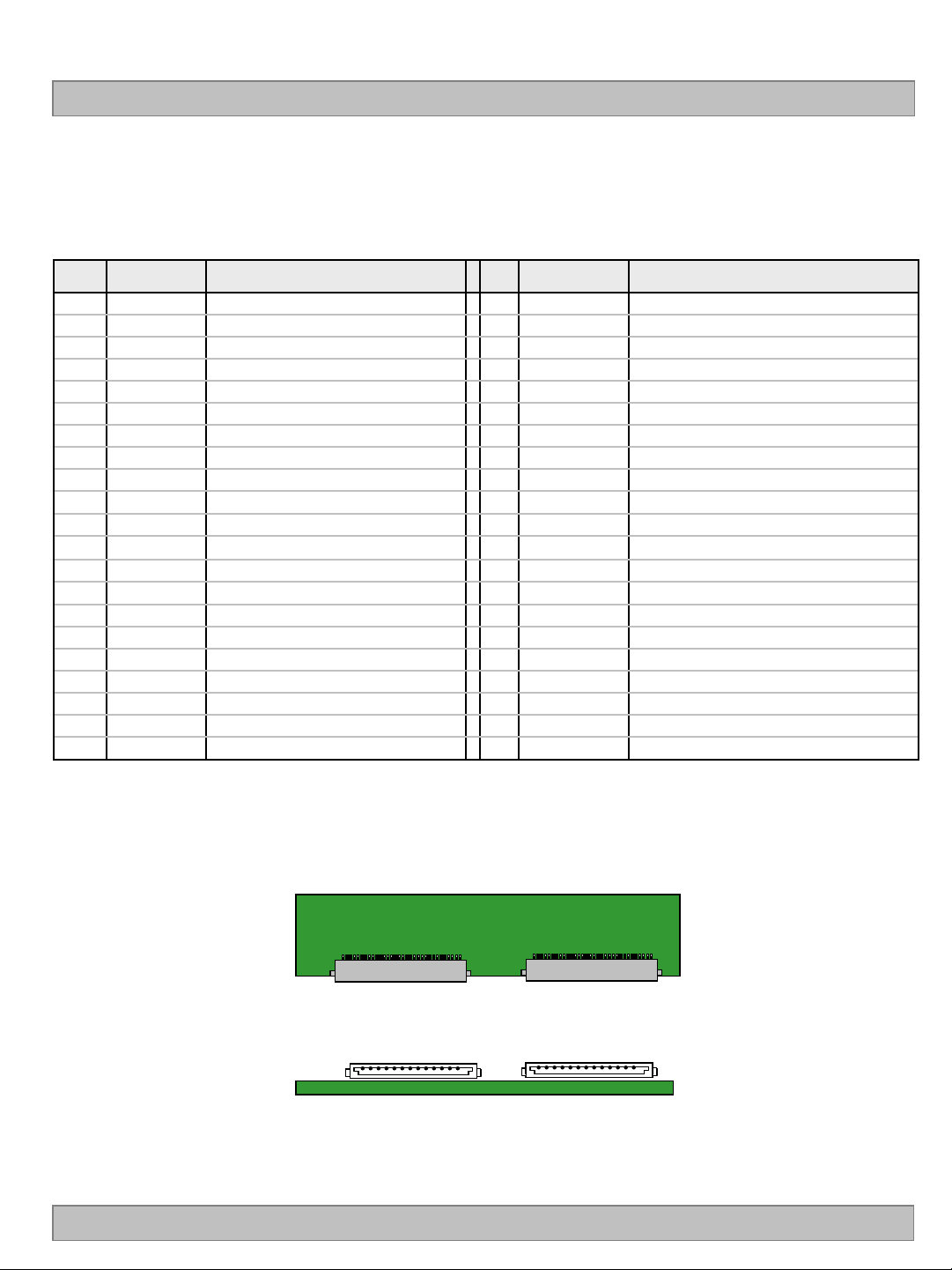
-LCD Connector (CN2) : FI-RE41S-HF (manufactured by JAE)
- Mating Connector : FI-RE41HL or compatible
Table 4-2. MODULE CONNECTOR(CN2) PIN CONFIGURATION
No Symbol Description No Symbol Description
1
2
3
4 NC
5
6
7
8
9
10
11
12
13 RB3P
14
15
16
17
18 RCLK3P
19
20
21
NC
NC
NC
NC
NC
NC
NC
GND
RA3N
RA3P
RB3N
RC3N
RC3P
GND
RCLK3N
GND
RD3N
RD3P
No connection 22
No connection 23
No connection 24 GND Ground
No connection
No connection
No connection 27
No connection 28
No connection 29 RB4P
Ground
THIRD LVDS Receiver Signal (A-)
THIRD LVDS Receiver Signal (A+)
THIRD LVDS Receiver Signal (B-)
THIRD LVDS Receiver Signal (B+)
THIRD LVDS Receiver Signal (C-)
THIRD LVDS Receiver Signal (C+)
Ground
THIRD LVDS Receiver Clock Signal(-)
THIRD LVDS Receiver Clock Signal(+)
Ground
THIRD LVDS Receiver Signal (D-)
THIRD LVDS Receiver Signal (D+)
25 GND Ground
26
30
31
32
33
34 RCLK4P
35
36
37
38
39
40 GND Ground
41 GND Ground
-
RE3N
RE3P
RA4N
RA4P
RB4N
RC4N
RC4P
GND
RCLK4N
GND
RD4N
RD4P
RE4N
RE4P
THIRD LVDS Receiver Signal (E-)
THIRD LVDS Receiver Signal (E+)
FORTH LVDS Receiver Signal (A-)
FORTH LVDS Receiver Signal (A+)
FORTH LVDS Receiver Signal (B-)
FORTH LVDS Receiver Signal (B+)
FORTH LVDS Receiver Signal (C-)
FORTH LVDS Receiver Signal (C+)
Ground
FORTH LVDS Receiver Clock Signal(-)
FORTH LVDS Receiver Clock Signal(+)
Ground
FORTH LVDS Receiver Signal (D-)
FORTH LVDS Receiver Signal (D+)
FORTH LVDS Receiver Signal (E-)
FORTH LVDS Receiver Signal (E+)
LC550EUF
Note : 1. All GND(ground) pins should be connected together to the LCD module’s metal frame.
2. LVDS pin (pin No. #22,23,38,39) are used for 10Bit(D) of the LCD module.
If used for 8Bit(R), these pins are no connection.
CN1 CN2
#1 #51 #1 #41
CN1 CN2
#1 #51
#1 #41
Rear view of LCM
Ver. 0.1
8 /38
Page 10
3-2-2. Backlight Module
LC550EUF
Product Specification
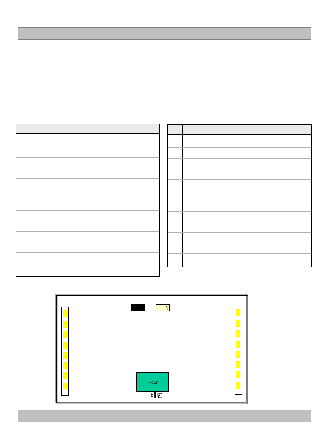
[ CN201 ]
1) LED Array Assy Connector (Plug)
: 20022HS-13B2(BK) (manufactured by Yeonho) or equivalent
2) Mating Connector (Receptacle)
: 20022WR-13BD (manufactured by Yeonho) or equivalent
[ CN202 ]
1) LED Array Assy Connector (Plug)
: 20022HS-12B2 (manufactured by Yeonho) or equivalent
2) Mating Connector (Receptacle)
: 20022WR-12BD (manufactured by Yeonho )or equivalent
Table 5. BACKLIGHT CONNECTOR PIN CONFIGURATION(CN201,CN202)
No Symbol
1
2
3
4
5
6
7
8
9
10
11
12
13
Anode_L1
(1~4Cathode)
N.C
L1 Cathode
L2 Cathode
L3 Cathode
L4 Cathode
N.C
L5 Cathode
L6 Cathode
L7 Cathode
L8 Cathode
N.C
Anode_L2
(5~8Cathode)
Description
LED Input Current
Open
LED Output Current
LED Output Current
LED Output Current
LED Output Current
Open
LED Output Current
LED Output Current
LED Output Current
LED Output Current
Open
LED Input Current
Note
No Symbol
1
2
3
4
5
6
7
8
9
10
11
12
Anode_R2
(5~8Cathode)
N.C
R8Cathode
R7 Cathode
R6 Cathode
R5 Cathode
R4 Cathode
R3 Cathode
R2 Cathode
R1 Cathode
N.C
Anode_R1
(1~4Cathode)
Description
LED Input Current
Open
LED Output Current
LED Output Current
LED Output Current
LED Output Current
LED Output Current
LED Output Current
LED Output Current
LED Output Current
Open
LED Input Current
Note
◆ Rear view of LCM
Ver. 0.1
13pin 12pin
L8
L7
L6
1
CN202 CN201
R8
R7
R6
L4 L5
R4 R5
L2 L3
L1
T-con
배면
R2 R3
R1
9 /38
Page 11
LC550EUF
Product Specification
3-3. Signal Timing Specifications
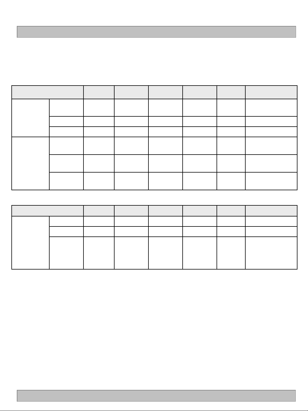
Table 6 shows the signal timing required at the input of the LVDS transmitter. All of the interface signal
timings should be satisfied with the following specification for normal operation.
Table 6. TIMING TABLE (DE Only Mode)
ITEM Symbol Min Typ Max Unit Note
Horizontal
Vertical
Frequency
Display
Period
Blank tHB 40 70 200 tCLK 1
Total tHP 520 550 680 tCLK
Display
Period
Blank tVB
Total tVP
tHV 480 480 480 tCLK 1920 / 4
tVV 1080 1080 1080 Lines
20
(228)
1100
(1308)
45
(270)
1125
(1350)
86
(300)
1166
(1380)
Lines 1
Lines
ITEM Symbol Min Typ Max Unit Note
DCLK fCLK 66.97 74.25 78.00 MHz
Horizontal fH 121.8 135 140 KHz 2
2
Vertical fV
108
(95)
120
(100)
122
(104)
Hz
NTSC: 108~122Hz
(PAL : 95~104Hz)
Note: 1. The input of HSYNC & VSYNC signal does not have an effect on normal operation (DE Only Mode).
If you use spread spectrum of EMI, add some additional clock to minimum value for clock margin.
2. The performance of the electro-optical characteristics may be influenced by variance of the vertical
refresh rate and the horizontal frequency
※ Timing should be set based on clock frequency.
Ver. 0.1
10 /38
Page 12
3-4. LVDS Signal Specification
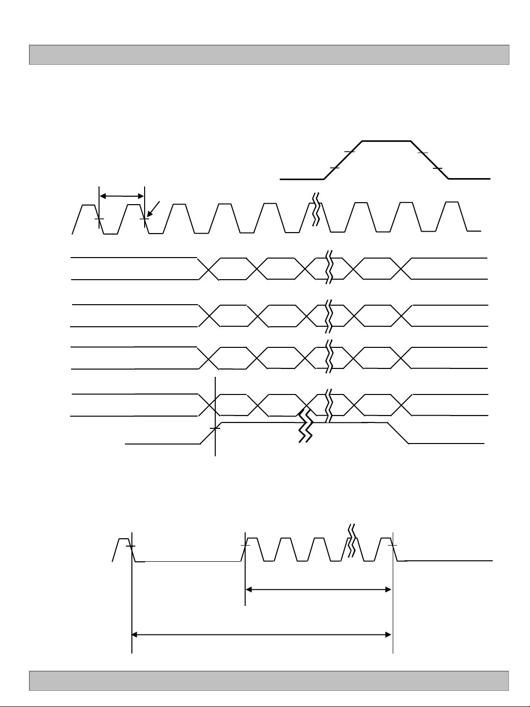
3-4-1. LVDS Input Signal Timing Diagram
LC550EUF
Product Specification
DCLK
First data
Second data
Third data
Forth data
DE(Data Enable)
tCLK
0.5 VDD
Invalid data
Invalid data
Invalid data
Invalid data
DE, Data
Valid data
Pixel 0
Valid data
Pixel 1
Valid data
Pixel 2
Valid data
Pixel 3
Pixel 4
Pixel 5
Pixel 6
Pixel 7
0.7VDD
0.3VDD
Invalid data
Invalid data
Invalid data
Invalid data
DE(Data Enable)
Ver. 0.1
1 1080
tVV
tVP
* tHB = tHFP + tWH +tHBP
* tVB = tVFP + tWV +tVBP
11 /38
Page 13
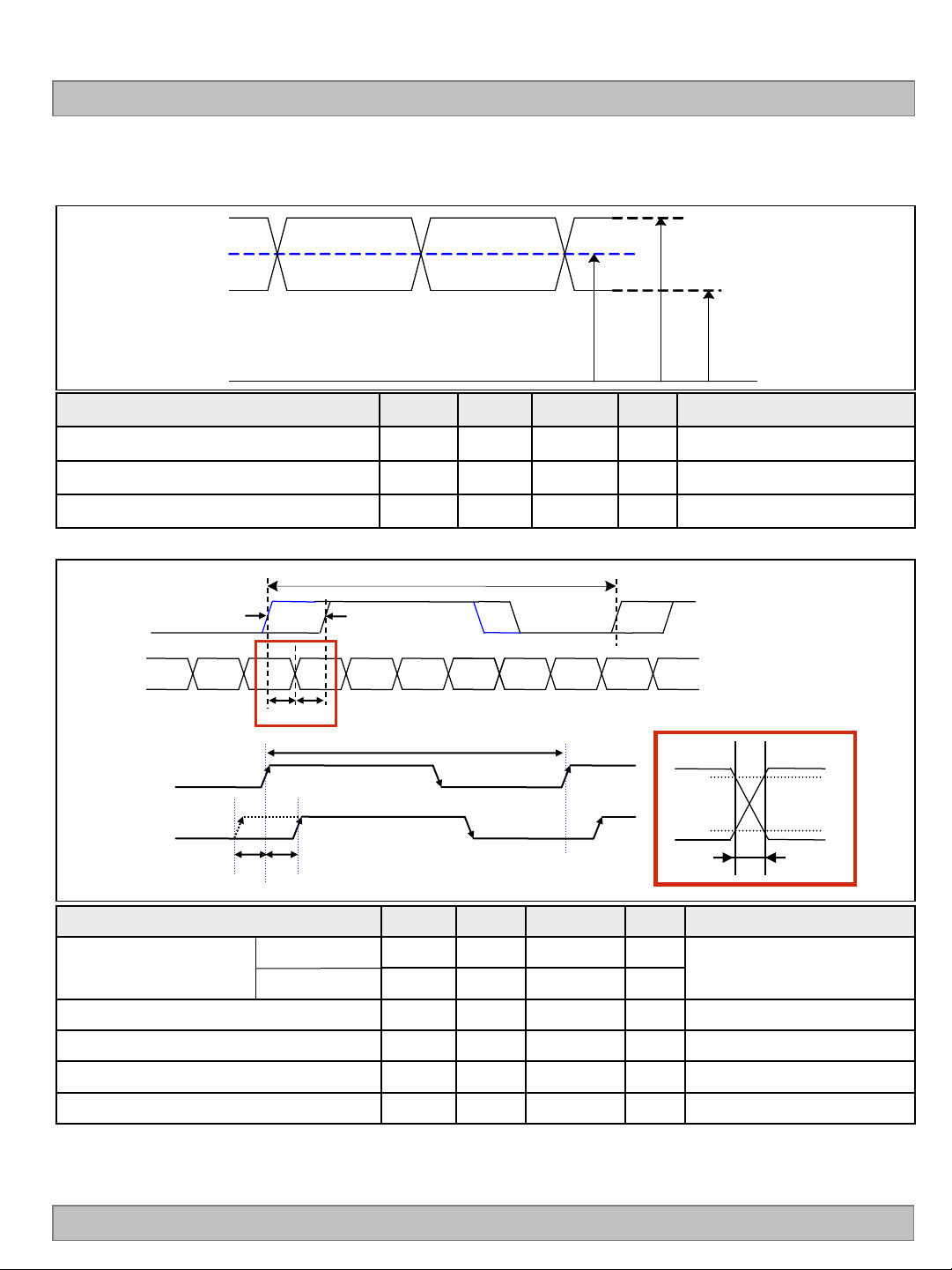
3-4-2. LVDS Input Signal Characteristics
1) DC Specification
LVDS -
LVDS +
LC550EUF
Product Specification
0 V
# V
= { ( LVDS +) + ( LVDS - ) } / 2
CM
V
CM
V
IN _ MAX V IN _ MIN
Description Symbol Min Max Unit Note
LVDS Common mode Voltage V
LVDS Input Voltage Range V
CM
IN
1.0 1.5 V -
0.7 1.8 V -
Change in common mode Voltage ΔVCM - 250 mV -
2) AC Specification
T
clk
LVDS Clock
A
LVDS Data
( F
= 1 / T
)
clk
A
LVDS 1’st Clock
LVDS 2nd / 3rd / 4th Clock
tSKEW
tSKEW
t
SKEW_min tSKEW_max
clk
T
clk
80%
20%
t
RF
Description Symbol Min Max Unit Note
LVDS Differential Voltage
High Threshold
Low Threshold
LVDS Clock to Data Skew t
LVDS Clock/DATA Rising/Falling time t
Effective time of LVDS t
LVDS Clock to Clock Skew (Even to Odd) t
1. All Input levels of LVDS signals are based on the EIA 644 Standard.
Note
2. If tRF isn’t enough, t
should be meet the range.
eff
3. LVDS Differential Voltage is defined within t
Ver. 0.1
VTH 100 300 mV
VTL -300 -100 mV
SKEW
RF
eff
SKEW_EO
- |(0.25*T
260 |(0.3*T
|±360|
- |1/7* T
eff
)/7| ps
clk
)/7| ps 2
clk
- ps
| ps -
clk
3
-
-
12 /38
Page 14
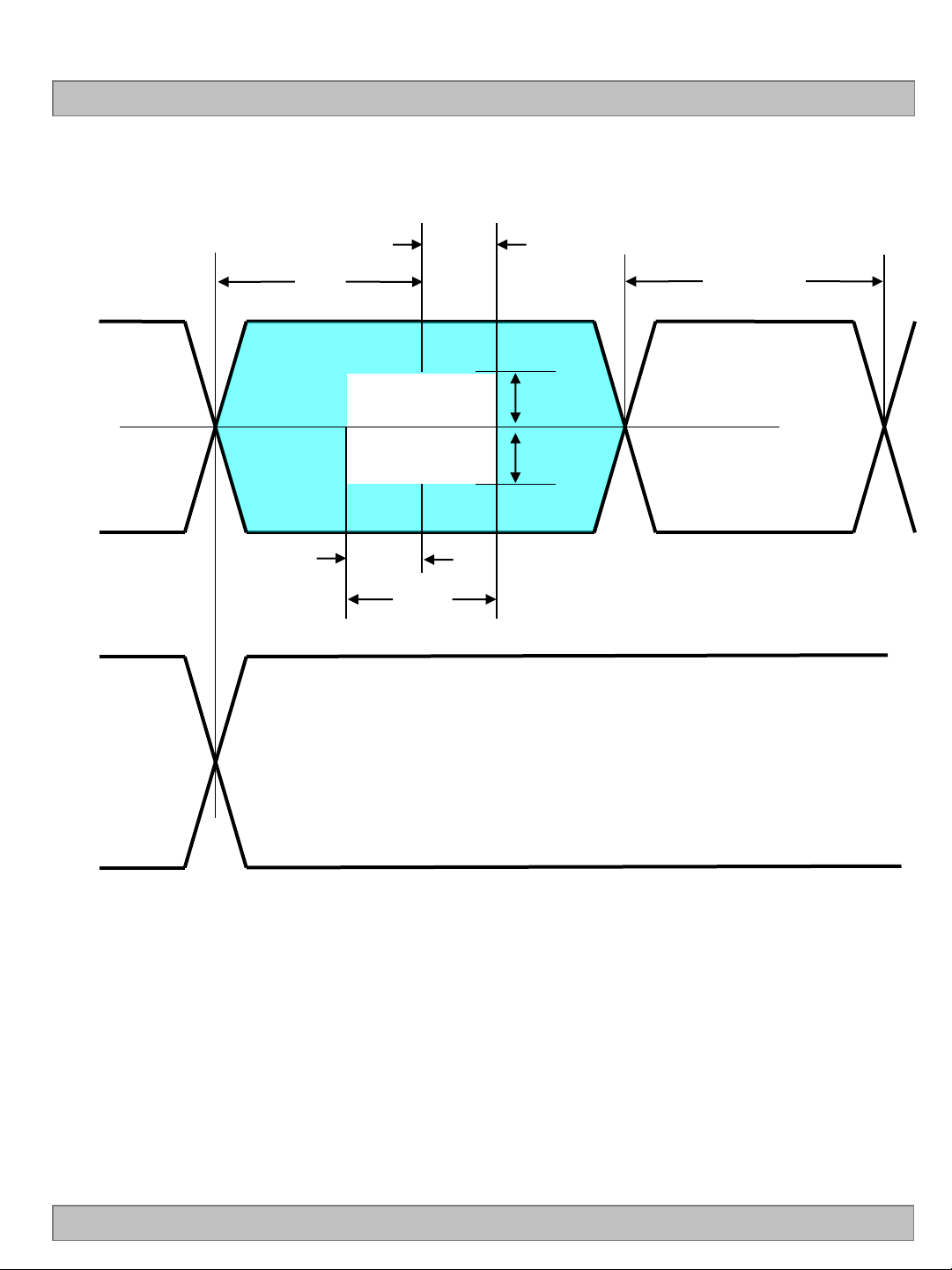
Product Specification
360ps
LC550EUF
V+
data
Vcm
Vdata
V+
clk
Vcm
0.5tui
tui
VTH
VTL
360ps
teff
tui : Unit Interval
Vclk
Ver. 0.1
13 /38
Page 15
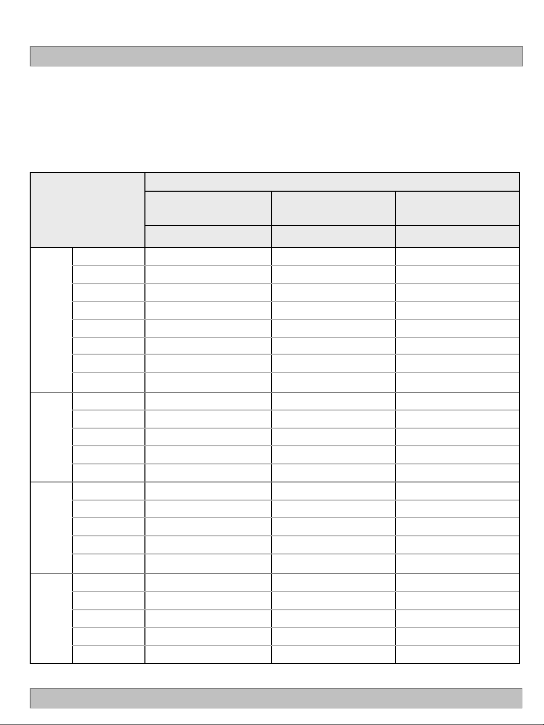
LC550EUF
Product Specification
3-5. Color Data Reference
The brightness of each primary color(red,green,blue) is based on the 10bit gray scale data input for the color.
The higher binary input, the brighter the color. Table 7 provides a reference for color versus data input.
Table 7. COLOR DATA REFERENCE
Input Color Data
Basic
Color
RED
Color
Black
Red (1023)
Green (1023)
Blue (1023)
Cyan
Magenta
Yellow
White
RED (0000)
RED (0001)
RED
MSB LSB
R9 R8 R7 R6 R5 R4 R3 R2 R1 R0 G9 G8 G7 G6 G5 G4 G3 G2 G1 G0 B9 B8 B7 B6 B5 B4 B3 B2 B1 B0
0 0 0 0 0 0 0 0 0 0 0 0 0 0 0 0 0 0 0 0 0 0 0 0 0 0 0 0 0 0
1 1 1 1 1 1 1 1 1 1 0 0 0 0 0 0 0 0 0 0 0 0 0 0 0 0 0 0 0 0
0 0 0 0 0 0 0 0 0 0 1 1 1 1 1 1 1 1 1 1 0 0 0 0 0 0 0 0 0 0
0 0 0 0 0 0 0 0 0 0 0 0 0 0 0 0 0 0 0 0 1 1 1 1 1 1 1 1 1 1
0 0 0 0 0 0 0 0 0 0 1 1 1 1 1 1 1 1 1 1 1 1 1 1 1 1 1 1 1 1
1 1 1 1 1 1 1 1 1 1 0 0 0 0 0 0 0 0 0 0 1 1 1 1 1 1 1 1 1 1
1 1 1 1 1 1 1 1 1 1 1 1 1 1 1 1 1 1 1 1 0 0 0 0 0 0 0 0 0 0
1 1 1 1 1 1 1 1 1 1 1 1 1 1 1 1 1 1 1 1 1 1 1 1 1 1 1 1 1 1
0 0 0 0 0 0 0 0 0 0 0 0 0 0 0 0 0 0 0 0 0 0 0 0 0 0 0 0 0 0
0 0 0 0 0 0 0 0 0 1 0 0 0 0 0 0 0 0 0 0 0 0 0 0 0 0 0 0 0 0
MSB LSB
GREEN
MSB LSB
… ... ... ...
RED (1022)
RED (1023)
GREEN (0000)
1 1 1 1 1 1 1 1 1 0 0 0 0 0 0 0 0 0 0 0 0 0 0 0 0 0 0 0 0 0
1 1 1 1 1 1 1 1 1 1 0 0 0 0 0 0 0 0 0 0 0 0 0 0 0 0 0 0 0 0
0 0 0 0 0 0 0 0 0 0 0 0 0 0 0 0 0 0 0 0 0 0 0 0 0 0 0 0 0 0
BLUE
GREEN
BLUE
Ver. 0.1
GREEN (0001)
...
GREEN (1022)
GREEN (1023)
BLUE (0000)
BLUE (0001)
0 0 0 0 0 0 0 0 0 0 0 0 0 0 0 0 0 0 0 1 0 0 0 0 0 0 0 0 0 0
... ... ...
0 0 0 0 0 0 0 0 0 0 1 1 1 1 1 1 1 1 1 0 0 0 0 0 0 0 0 0 0 0
0 0 0 0 0 0 0 0 0 0 1 1 1 1 1 1 1 1 1 1 0 0 0 0 0 0 0 0 0 0
0 0 0 0 0 0 0 0 0 0 0 0 0 0 0 0 0 0 0 0 0 0 0 0 0 0 0 0 0 0
0 0 0 0 0 0 0 0 0 0 0 0 0 0 0 0 0 0 0 0 0 0 0 0 0 0 0 0 0 1
… ... ... ...
BLUE (1022)
BLUE (1023)
0 0 0 0 0 0 0 0 0 0 0 0 0 0 0 0 0 0 0 0 1 1 1 1 1 1 1 1 1 0
0 0 0 0 0 0 0 0 0 0 0 0 0 0 0 0 0 0 0 0 1 1 1 1 1 1 1 1 1 1
14 /38
Page 16
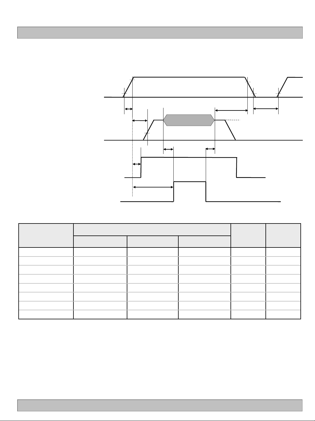
3-6. Power Sequence
3-6-1. LCD Driving circuit
LC550EUF
Product Specification
Power Supply For LCD
V
LCD
Interface Signal (Tx_clock)
User Control Signal
(LVDS_select, BIT _select)
Power for LED
Table 8. POWER SEQUENCE
Parameter
90%
10%
0V
T1
T2
30%
0V
100%
T6
T7
Valid Data
T3 T4
LED ON
Value
Min Typ Max
90%
10%
T8
T5
Vcm : LVDS Common mode Voltage
Unit Notes
10%
Note :
Ver. 0.1
T1 0.5 - 20 ms 1
T2 0 - - ms 2
T3 200 - - ms 3
T4 200 - - ms 3
T5 1.0 - - s 4
T6 - - T2 ms 5
T7 0.5 - - s 6
T8 100 - - ms 7
1. Even though T1 is over the specified value, there is no problem if I2T spec of fuse is satisfied.
2. If T2 is satisfied with specification after removing LVDS Cable, there is no problem.
3. The T3 / T4 is recommended value, the case when failed to meet a minimum specification,
abnormal display would be shown. There is no reliability problem.
4. T5 should be measured after the Module has been fully discharged between power off and on period.
5. If the on time of signals (Interface signal and user control signals) precedes the on time of Power (V
it will be happened abnormal display. When T6 is NC status, T6 doesn’t need to be measured.
6. If there is no abnormal display, no problem.
7. It is recommendation specification that T8 has to be 100ms as a minimum value.
※ Please avoid floating state of interface signal at invalid period.
※ When the power supply for LCD (VLCD) is off, be sure to pull down the valid and invalid data to 0V.
LCD
),
15 /38
Page 17
LC550EUF
Product Specification
4. Optical Specification
Optical characteristics are determined after the unit has been ‘ON’ and stable in a dark environment at 25±2°C.
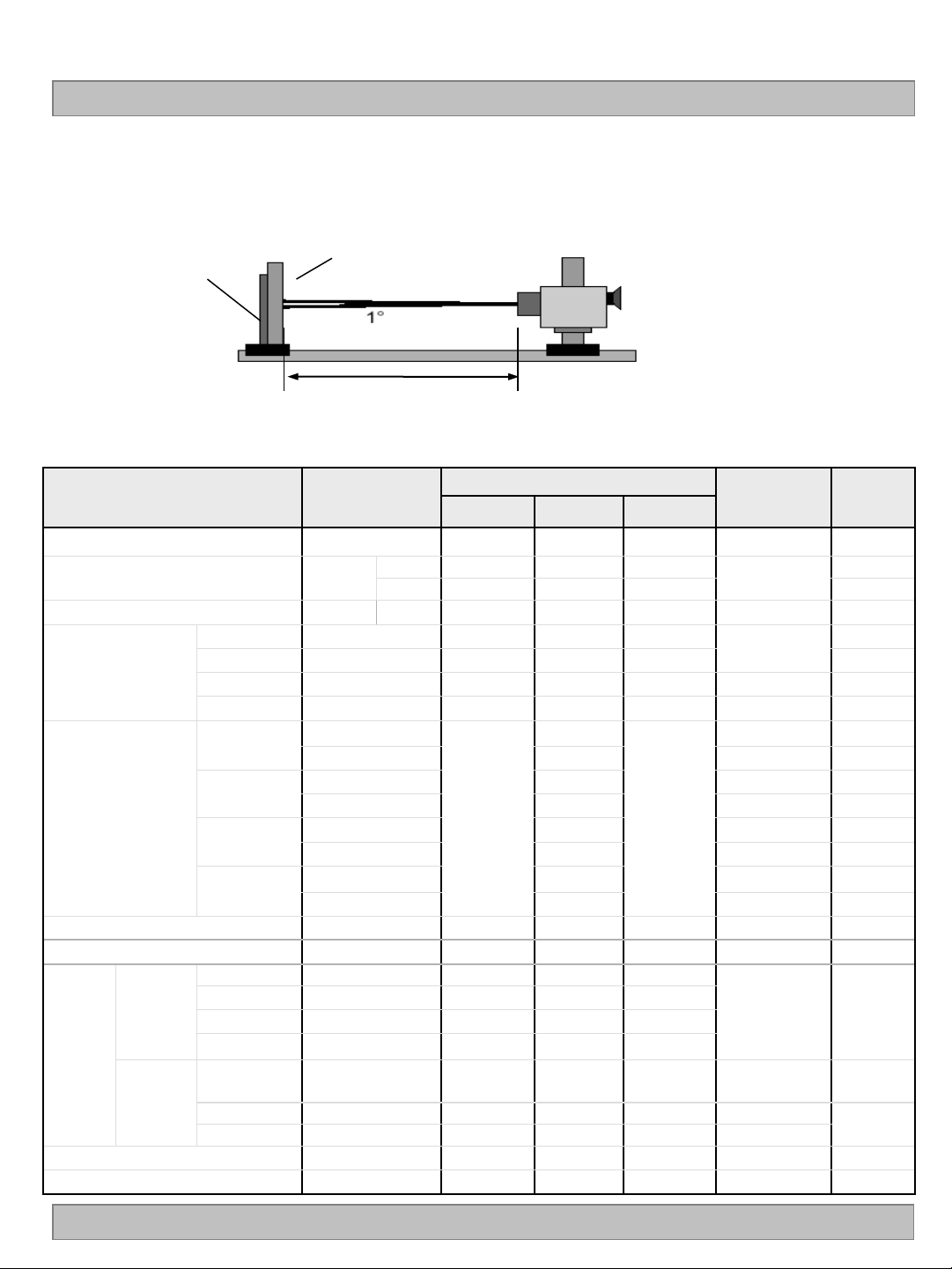
The values are specified at distance 50cm from the LCD surface at a viewing angle of and equal to 0 °.
FIG. 1 shows additional information concerning the measurement equipment and method.
Optical Stage(x,y)
LCD Module
Pritchard 880 or
equivalent
50cm
FIG. 1 Optical Characteristic Measurement Equipment and Method
Table 10. OPTICAL CHARACTERISTICS
Ta= 25±2°C, V
=12.0V, fV=120Hz, Dclk =74.25MHz
LCD
IF_cathode=100mA
Value
Parameter Symbol
Contrast Ratio CR 1100 1600 - 1
Surface Luminance, white L
Luminance Variation
Gray-to-Gray G to G - 5 8
Response Time
MPRT MPRT - 6 9 5
Uniformity
Uniformity
RED
Color Coordinates
[CIE1931]
GREEN
BLUE
WHITE
WH
WHITE
2D 320 400
3D 120 150 7
5P 1.35 3
MPRT
G TO G
Rx
Ry 0.333
Gx 0.307
Gy 0.602
Bx 0.150
By 0.060
Wx 0.279
Wy 0.292
Min Typ Max
- - 1 5
- - 1 5
0.651
Typ
-0.03
Typ
+0.03
Color Temperature 10,000 K
Color Gamut 72 %
right(=0°)
2D
Viewing
Angle
3D Crosstalk 3D C/T 1 3 % 7
Gray Scale - 2.2 - 8
(CR>10)
3D
(CT≤10%)
left (=180°)
up (=90°)
down (=270°)
up + down
up u (y axis) 10
down d (y axis) 10
r (x axis) 89 - -
l (x axis) 89 - -
u (y axis) 89 - -
d (y axis) 89 - -
u (y axis)
+d (y axis)
22 26 - 7
Unit Note
2
cd/m
ms
degree 6
7,9
2
4
Ver. 0.1
16 /38
Page 18
LC550EUF
Product Specification
Notes :1. Contrast Ratio(CR) is defined mathematically as :
Surface Luminance at all white pixels
CR =
Surface Luminance at all black pixels
It is measured at center 1-point.
2. Surface luminance is determined after the unit has been ‘ON’ and 1Hour after lighting the
backlight in a dark environment at 25±2°C. Surface luminance is the luminance value at center
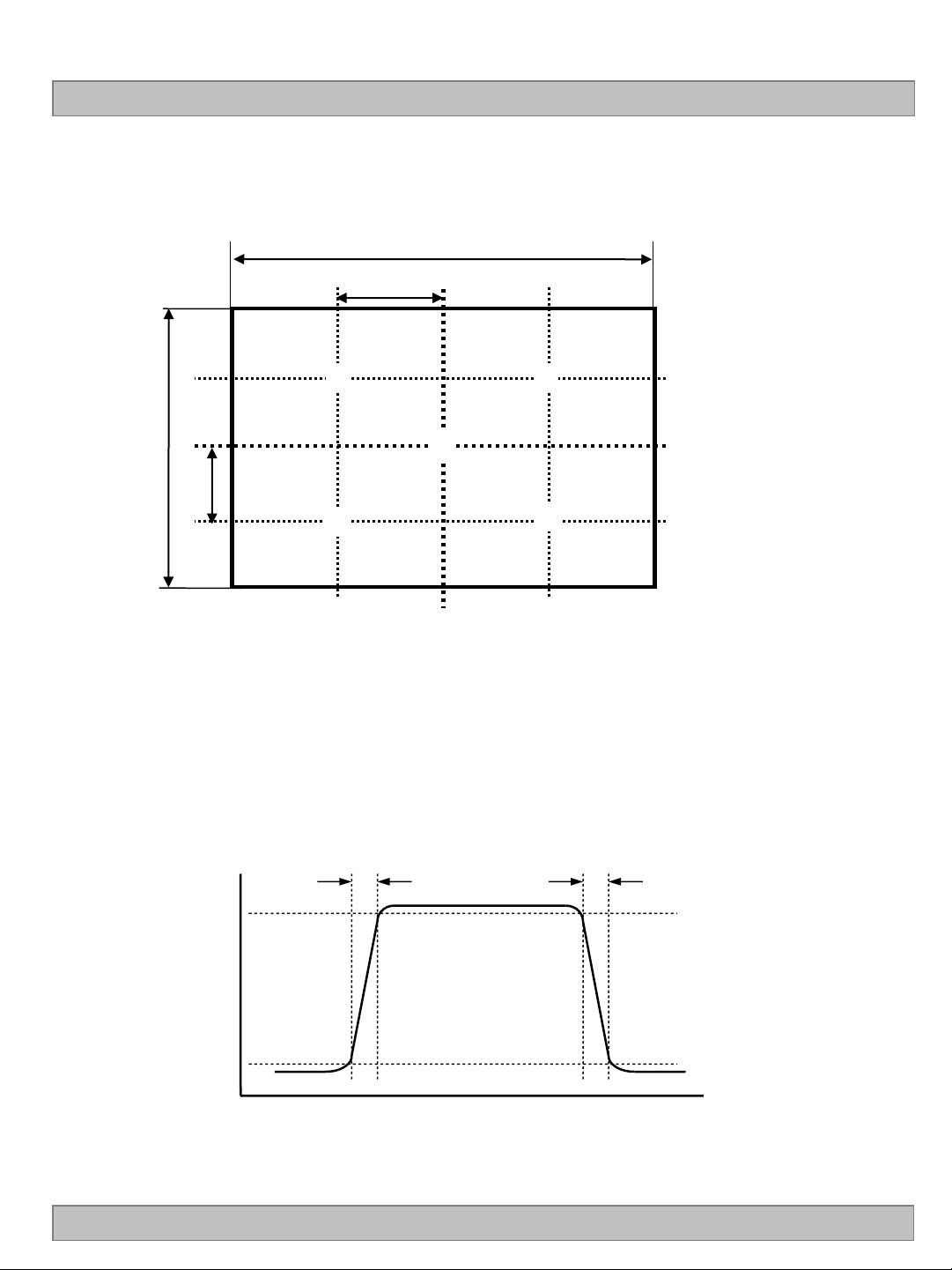
1-point across the LCD surface 50cm from the surface with all pixels displaying white.
For more information see the FIG. 2.
3. The variation in surface luminance , WHITE is defined as :
WHITE(5P) = Maximum(L
Where L
on1
to L
are the luminance with all pixels displaying white at 5 locations .
on5
on1,Lon2
For more information, see the FIG. 2.
4. Response time is the time required for the display to transit from G(N) to G(M) (Rise Time, TrR)
and from G(M) to G(N) (Decay Time, TrD). For additional information see the FIG. 3. (N<M)
※ G to G Spec stands for average value of all measured points.
Photo Detector : RD-80S / Field : 2 °
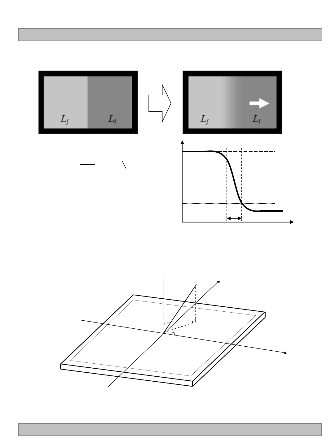
5. MPRT is defined as 10% to 90% blur-edge width Bij(pixels) and scroll speed U(pixels/frame)at
the moving picture. For more information, see FIG 4
※ Gray to Gray and MPRT Response time uniformity is Reference data. Appendix VIII-1/VIII-2
6. Viewing angle is the angle at which the contrast ratio is greater than 10. The angles are
determined for the horizontal or x axis and the vertical or y axis with respect to the z axis which
is normal to the LCD module surface. For more information, see the FIG. 5.
7. 3D performance specification is expressed by 3D luminance, 3D Crosstalk and 3D viewing angle.
3D luminance and 3D crosstalk is measured at center 1-point.
For more information, see the FIG 6~9.
8. Gray scale specification
Gamma Value is approximately 2.2. For more information, see the Table 11.
9. The Spec. of 3D viewing angle is temporarily permitted by 8˚ until 2Q of 2011.
, L
on3
, L
on4
, L
) / Minimum(L
on5
on1,Lon2
, L
on3
, L
on4
, L
on5
)
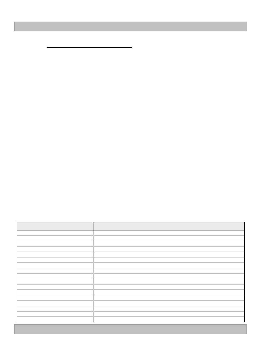
Table 11. GRAY SCALE SPECIFICATION
Gray Level Luminance [%] (Typ.)
L0
L63
L127
L191
L255
L319
L383
L447
L511
L575
L639
L703
L767
L831
L895
L959
L1023
Ver. 0.1
0.07
0.27
1.04
2.49
4.68
7.66
11.5
16.1
21.6
28.1
35.4
43.7
53.0
63.2
74.5
86.7
100
17 /38
Page 19
Product Specification
Measuring point for surface luminance & measuring point for luminance variation.
H
A
③ ②
LC550EUF
V
①
B
A : H / 4 mm
④
FIG. 2 5 Points for Luminance Measure
Response time is defined as the following figure and shall be measured by switching the input signal for
“Gray(N)” and “Gray(M)”.
TrR
100
90
⑤
TrD
B : V / 4 mm
@ H,V : Active Area
Ver. 0.1
Optical
Response
10
0
Gray(N)
Gray(M)
N,M = Black~White, N<M
FIG. 3 Response Time
Gray(N)
18 /38
Page 20
LC550EUF
Normal
Y
E
= 0, Right
= 180, Left
= 270, Down
= 90, Up
Product Specification
MPRT is defined as the 10% to 90% blur-edge with Bij(pixels) and scroll speed U(pixels/frame)at the moving
picture.
1
M =
Bij (i=j)
U
Example) Bij = 12pixels, U = 10pixels / 120Hz
M = 12pixels / (10pixels / 120Hz)
= 12pixels / {10pixels / (1/120)s}
= 12 / 1,200 s
= 10 ms
Dimension of viewing angle range
Lj
Li
FIG. 4 MPRT
90%
10%
Bij
Ver. 0.1
FIG. 5 Viewing Angle
19 /38
Page 21
Product Specification
LC550EUF
LW-RW
LW-RB
LB-RW
LB-RB
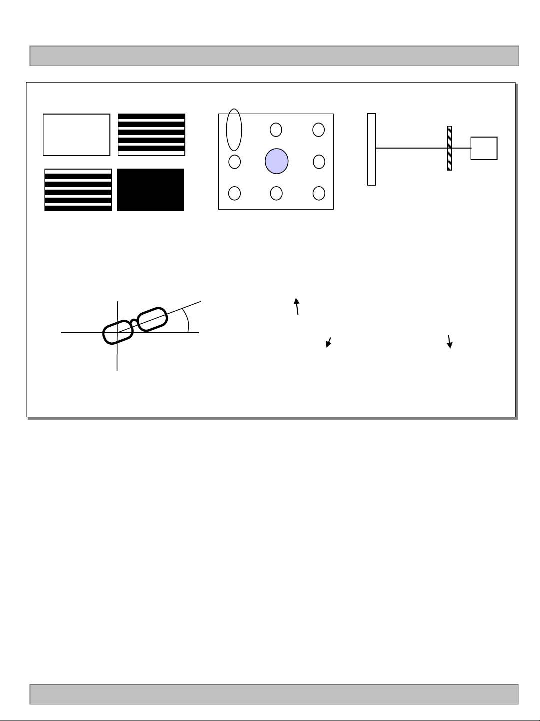
(a) Test pattern image
< FIG.7. Positioning eyeglass >
2
6
4 5
7
1
9
3
8
3D display
(b) Measurement
position
< FIG.6. Measurement configuration>
Luminance
Lum( LE or RE, test pattern, number )
Measurement through
Left or Right eyeglass
< FIG. 8. notation of luminance measurement >
LMS
Right or left eyeglass
( Circular polarizer )
(c) Setup
measurement
position
In order to measure 3D luminance, 3D crosstalk and 3D viewing angle, it need to be prepared as below;
1) Measurement configuration
4-Test pattern images. Refer to FIG 8.
-. LW-RW : White for left and right eye
-. LW-RB : White for left eye and Black for right eye
-. LB-RW : Black for left eye and white for right eye
-. LB-RB : Black for left eye and right eye
Image files where black and white lines are displayed on even or odd lines.
Luminance measurement system (LMS) with narrow FOV (field of view) is used. Refer to FIG 1.
2) Positioning Eyeglass (refer to appendix-VIII for standard specification of eyeglass)
Find angle of minimum transmittance.
This value would be provided beforehand or measured by the following steps;
(i) Test image (LB-RW) is displayed.
(ii) Left eyeglass are placed in front of LMS and luminance is measured,
rotating right eyeglass such as FIG 7. The notation for luminance measurement is “Lum(LE, LB-RW,1)”.
(iii) Find the angle where luminance is minimum.
* Following measurements should be performed at the angle of minimum transmittance of eyeglass.
Ver. 0.1
20 /38
Page 22
LC550EUF
Product Specification
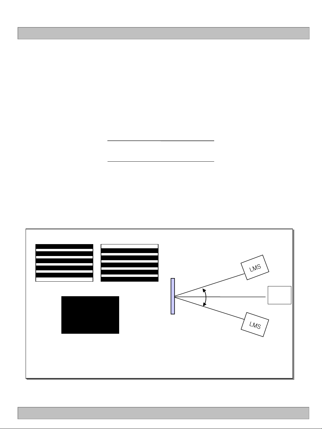
3) Measurement of 3D luminance
(i) Test image ( LW-RW ) is displayed.
(ii) Left or right eyeglass are placed in front of LMS successively and
luminance is measured at center 1 point where the notation for luminance measurement is
“Lum(LE, LW-RW,1)” or “Lum(RE, LW-RW,1).
4) Measurement of 3D crosstalk
(i) Test image ( LB-RW, LW-RB and LB-RB ) is displayed.
(ii) Right or left eyeglass are placed in front of LMS successively and
luminance is measured for position 1.
with rotating LMS or sample vertically.
Average of
and
5) Measurement of 3D Viewing Angle
3D viewing angle is the angle at which the 3D crosstalk is under 10%. The angles are
determined for the vertical or y axis with respect to the z axis which is normal to the LCD
module surface and measured for position 1. For more information , see the Fig 9
Lum(LE, LB-RW,1) - Lum(LE, LB-RB,1)
Lum(LE, LW-RB,1) - Lum(LE, LB-RB,1)
Lum(RE, LW-RB,1) - Lum(RE, LB-RB,1)
Lum(RE, LB-RW,1) - Lum(RE, LB-RB,1)
Ver. 0.1
y axis
LB-RW LW-RB
LCM
LB-RB
(a) Test pattern image
(b) Measurement of 3D viewing angle (up/down)
< FIG.9. Measurement of 3D crosstalk and 3D viewing angle >
Φyu(up)
Φyd (down)
z axis
LMS
21 /38
Page 23
Product Specification
5. Mechanical Characteristics
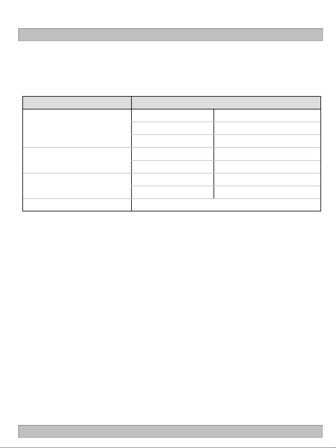
Table 12 provides general mechanical characteristics.
Table 12. MECHANICAL CHARACTERISTICS
Item Value
Horizontal 1253.6 mm
LC550EUF
Outline Dimension
Bezel Area
Active Display Area
Weight 14.5㎏(Typ_TBD),15.0kg(Max_TBD)
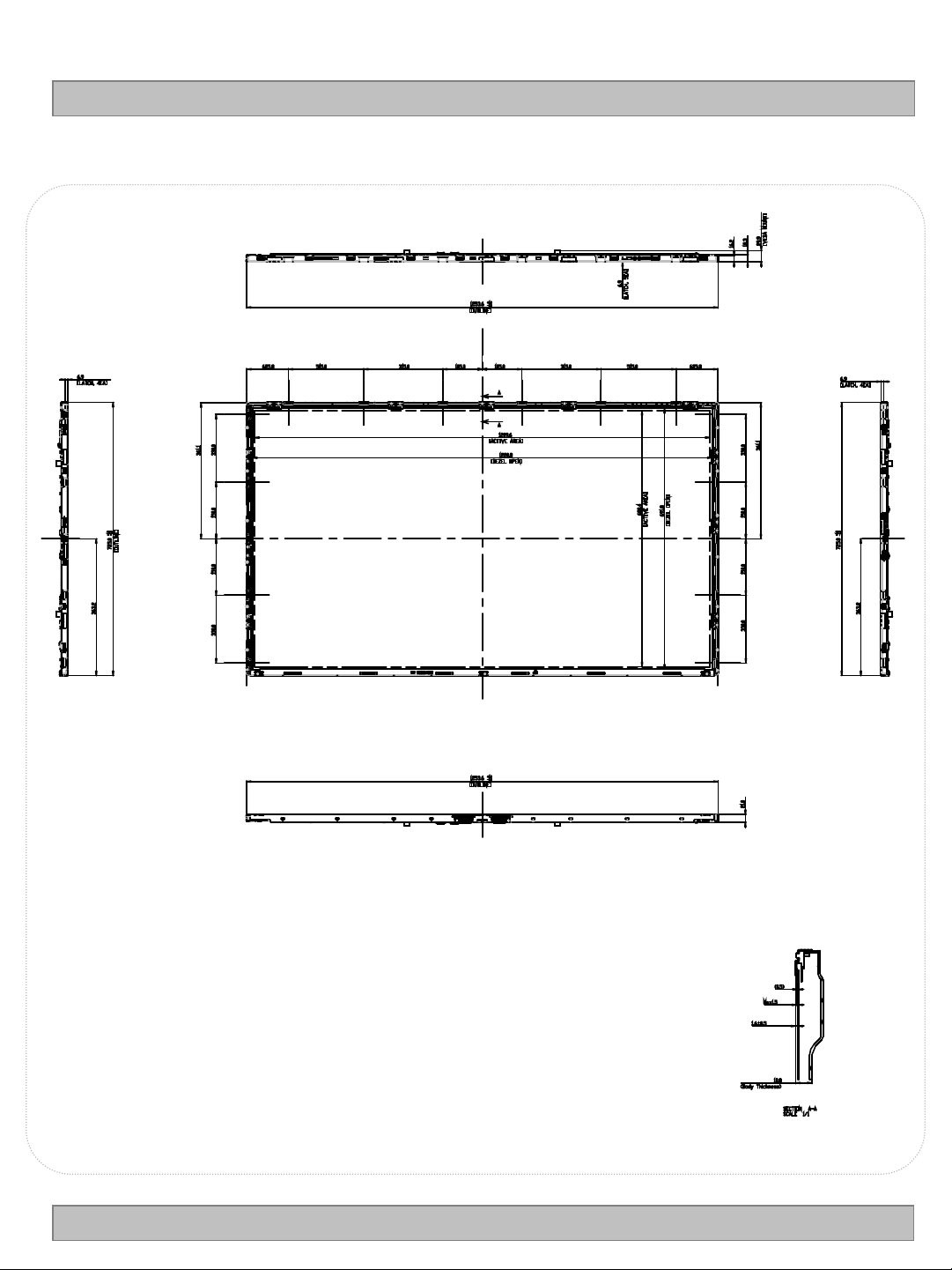
Note : Please refer to a mechanical drawing in terms of tolerance at the next page.
Vertical 725.0 mm
Depth 10.8 mm (B) / 21.0mm (D)
Horizontal 1220.8 mm
Vertical 680.4 mm
Horizontal 1209.6 mm
Vertical 680.4 mm
Ver. 0.1
22 /38
Page 24
<FRONT VIEW>
LC550EUF
Product Specification
Ver. 0.1
23 /38
Page 25
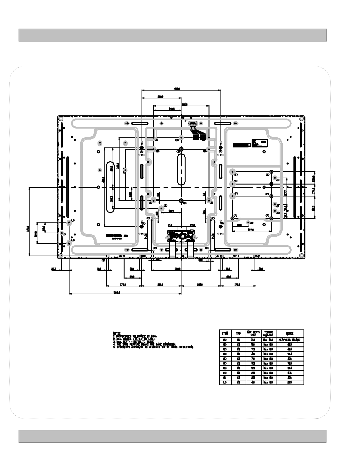
<REAR VIEW>
LC550EUF
Product Specification
Ver. 0.1
24 /38
Page 26

Product Specification
6. International Standards
6-1. Environment
a) RoHS, Directive 2002/95/EC of the European Parliament and of the council of 27 January 2003
LC550EUF
Ver. 0.1
25 /38
Page 27

LC550EUF
Product Specification
7. Precautions
Please pay attention to the followings when you use this TFT LCD module.
7-1. Mounting Precautions
(1) You must mount a module using specified mounting holes (Details refer to the drawings).
(2) You should consider the mounting structure so that uneven force (ex. Twisted stress) is not applied to
the
module. And the case on which a module is mounted should have sufficient strength so that external
force is not transmitted directly to the module.
(3) Please attach the surface transparent protective plate to the surface in order to protect the polarizer.
Transparent protective plate should have sufficient strength in order to the resist external force.
(4) You should adopt radiation structure to satisfy the temperature specification.
(5) Acetic acid type and chlorine type materials for the cover case are not desirable because the former
generates corrosive gas of attacking the polarizer at high temperature and the latter causes circuit break
by electro-chemical reaction.
(6) Do not touch, push or rub the exposed polarizers with glass, tweezers or anything harder than HB
pencil lead. And please do not rub with dust clothes with chemical treatment.
Do not touch the surface of polarizer for bare hand or greasy cloth.(Some cosmetics are detrimental
to the polarizer.)
(7) When the surface becomes dusty, please wipe gently with absorbent cotton or other soft materials like
chamois soaks with petroleum benzine. Normal-hexane is recommended for cleaning the adhesives
used to attach front / rear polarizers. Do not use acetone, toluene and alcohol because they cause
chemical damage to the polarizer
(8) Wipe off saliva or water drops as soon as possible. Their long time contact with polarizer causes
deformations and color fading.
(9) Do not open the case because inside circuits do not have sufficient strength.
7-2. Operating Precautions
(1) The spike noise causes the mis-operation of circuits. It should be lower than following voltage :
V=±200mV(Over and under shoot voltage)
(2) Response time depends on the temperature.(In lower temperature, it becomes longer.)
(3) Brightness depends on the temperature. (In lower temperature, it becomes lower.)
And in lower temperature, response time(required time that brightness is stable after turned on)
becomes longer
(4) Be careful for condensation at sudden temperature change.Condensation makes damage to polarizer or
electrical contacted parts. And after fading condensation, smear or spot will occur.
(5) When fixed patterns are displayed for a long time, remnant image is likely to occur.
(6) Module has high frequency circuits. Sufficient suppression to the electromagnetic interference shall be
done by system manufacturers. Grounding and shielding methods may be important to minimized the
interference.
(7) Please do not give any mechanical and/or acoustical impact to LCM. Otherwise, LCM can’t be operated
its full characteristics perfectly.
(8) A screw which is fastened up the steels should be a machine screw.
(if not, it can causes conductive particles and deal LCM a fatal blow)
(9) Please do not set LCD on its edge.
Ver. 0.1
26 /38
Page 28

LC550EUF
Product Specification
7-3. Electrostatic Discharge Control
Since a module is composed of electronic circuits, it is not strong to electrostatic discharge. Make certain that
treatment persons are connected to ground through wrist band etc. And don’t touch interface pin directly.
7-4. Precautions for Strong Light Exposure
Strong light exposure causes degradation of polarizer and color filter.
7-5. Storage
When storing modules as spares for a long time, the following precautions are necessary.
(1) Store them in a dark place. Do not expose the module to sunlight or fluorescent light. Keep the temperature
between 5°C and 35°C at normal humidity.
(2) The polarizer surface should not come in contact with any other object.
It is recommended that they be stored in the container in which they were shipped.
(3) Storage condition is guaranteed under packing conditions.
(4) The phase transition of Liquid Crystal in the condition of the low or high storage temperature will be
recovered when the LCD module returns to the normal condition
7-6. Handling Precautions for Protection Film
(1) The protection film is attached to the bezel with a small masking tape.
When the protection film is peeled off, static electricity is generated between the film and polarizer.
This should be peeled off slowly and carefully by people who are electrically grounded and with well ion-
blown equipment or in such a condition, etc.
(2) When the module with protection film attached is stored for a long time, sometimes there remains a very
small amount of glue still on the bezel after the protection film is peeled off.
(3) You can remove the glue easily. When the glue remains on the bezel surface or its vestige is recognized,
please wipe them off with absorbent cotton waste or other soft material like chamois soaked with normal hexane.
7-7. Operating condition guide
(1) The LCD product should be operated under normal conditions. Normal condition is defined as below;
- Temperature : 5 ~ 40 ℃
- Display pattern : continually changing pattern (Not stationary)
(2) If the product will be used in extreme conditions such as high temperature, display patterns or operation
time etc..,
It is strongly recommended to contact LGD for Qualification engineering advice. Otherwise, its reliability
and function may not be guaranteed. Extreme conditions are commonly found at Airports, Transit Stations,
Banks, Stock market, and Controlling systems. The LCD product should be applied by global standard
environment. (refer ETSI EN 300, IEC 60721)
Ver. 0.1
27 /38
Page 29
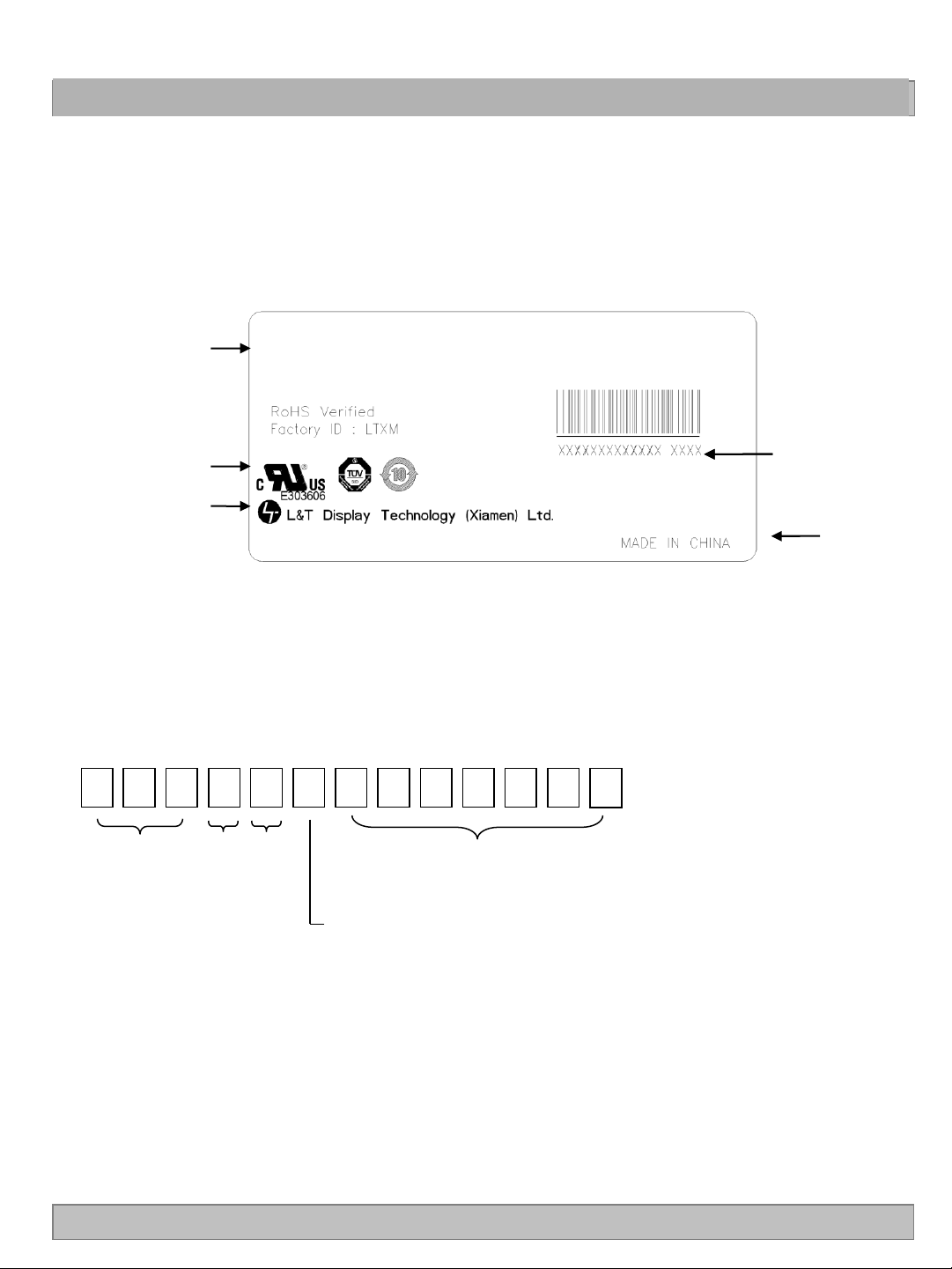
# APPENDIX-I
■ LC550EUF-LDC1-LCM Label
LC550EUF
Product Specification
Model
LC550EUF
(LD)(C1)
UL, TUV Mark
L&T Logo
■ Serial No.
1 2 3 4 5 6 7 9 10 11 12
Inch
Month Year
8
Serial No.
Serial No.
Origin
13
Ver. 0.1
M Ass’y Factory code
28 /38
Page 30
LC550EUF
Product Specification
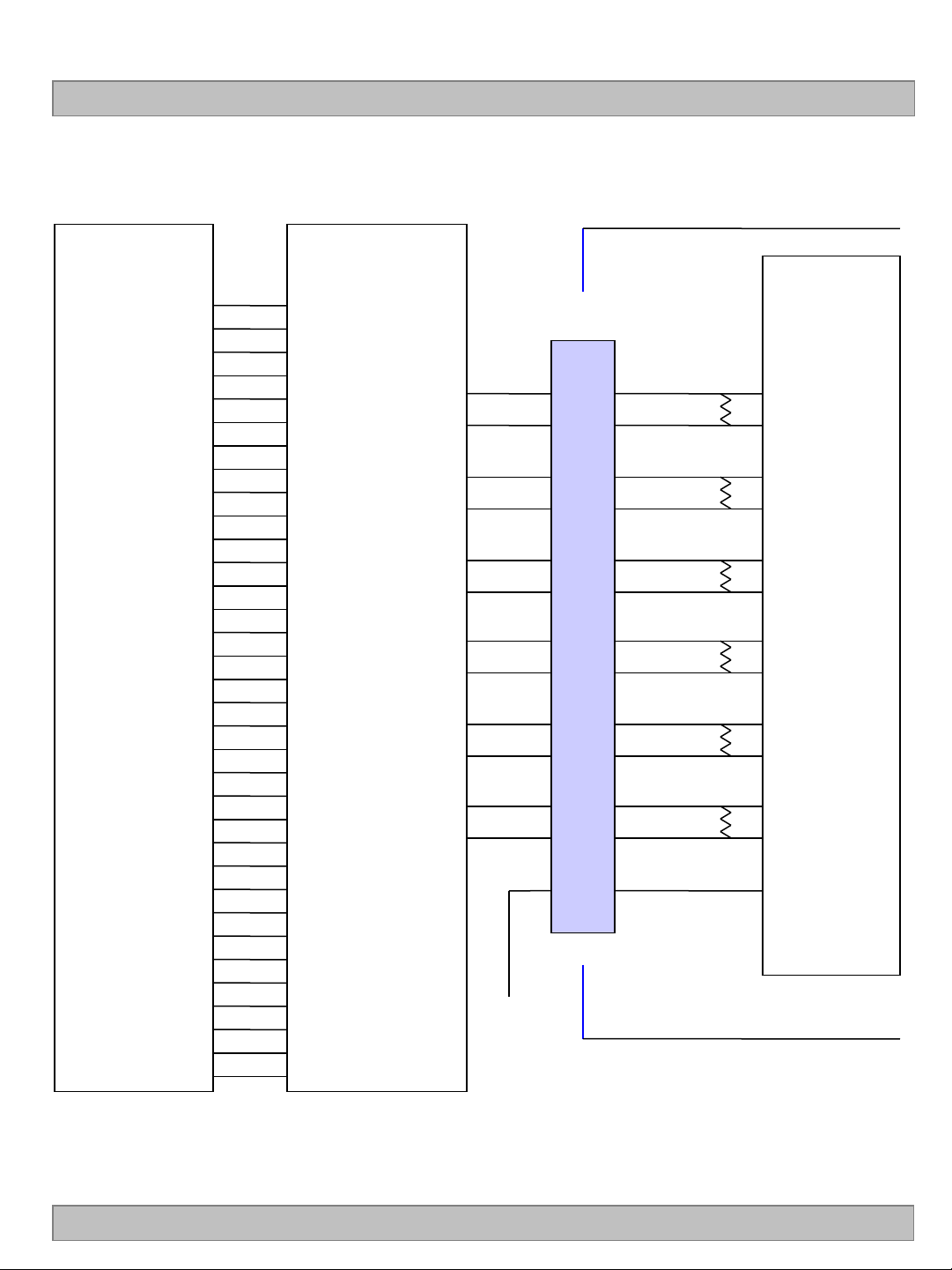
# APPENDIX- II-1
■ Required signal assignment for Flat Link (Thine : THC63LVD103) Transmitter(Pin7= “L” or “NC”)
Host System
30 Bit
RED0
RED1
RED2
RED3
RED4
RED5
RED6
RED7
RED8
RED9
GREEN0
GREEN1
GREEN2
GREEN3
GREEN4
GREEN5
GREEN6
GREEN7
GREEN8
GREEN9
BLUE0
BLUE1
BLUE2
BLUE3
BLUE4
BLUE5
BLUE6
BLUE7
BLUE8
BLUE9
Hsync
Vsync
Data Enable
CLOCK
THC63LVD103
or Compatible
33
34
35
36
37
38
59
61
4
5
40
41
42
44
45
46
62
63
6
8
48
49
50
52
53
54
64
1
9
11
55
57
58
12
TA-
TA+
TB-
TB+
TC-
TC+
TCLK-
TCLK+
TD-
TD+
TE-
TE+
Timing
Controller
FI-RE51S-HF
31
30
29
28
25
24
23
22
21
20
19
18
GND
12
13
14
15
16
17
19
20
22
23
24
25
7
100Ω
100Ω
100Ω
100Ω
100Ω
100Ω
LCM Module
RO0N
RO0P
RO1N
RO1P
RO2N
RO2P
ROCLKN
ROCLKP
RO3N
RO3P
RO4N
RO4P
VESA/ JEIDA
Note: 1. The LCD module uses a 100 Ohm[Ω] resistor between positive and negative lines of each receiver
input.
2. Refer to LVDS Transmitter Data Sheet for detail descriptions. (THC63LVD103 or Compatible)
3. ‘9’ means MSB and ‘0’ means LSB at R,G,B pixel data.
Ver. 0.1
29 /38
Page 31
Product Specification
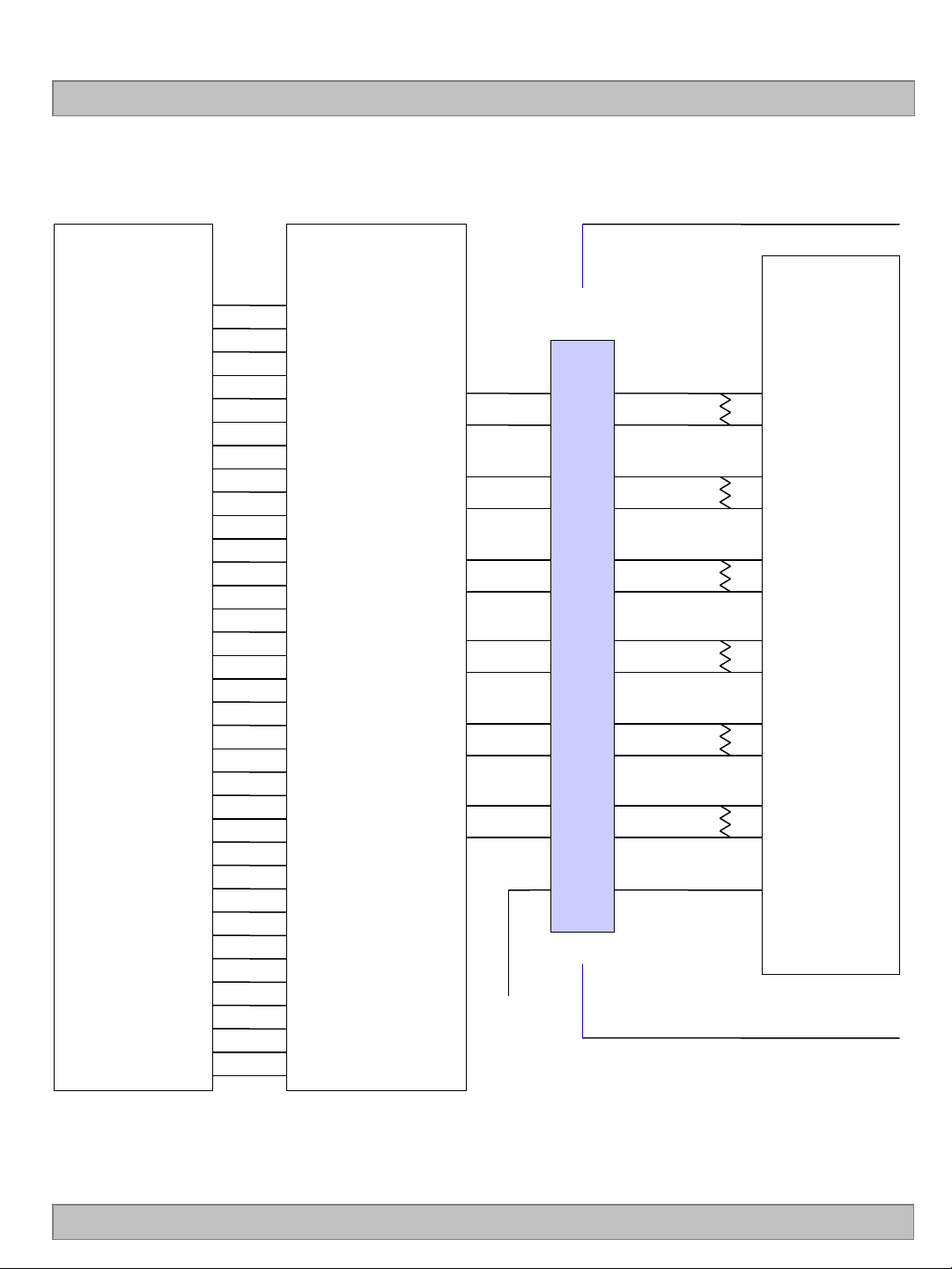
# APPENDIX- II-2
■ Required signal assignment for Flat Link (Thine : THC63LVD103) Transmitter(Pin7= “H” )
LC550EUF
Host System
30 Bit
RED0
RED1
RED2
RED3
RED4
RED5
RED6
RED7
RED8
RED9
GREEN0
GREEN1
GREEN2
GREEN3
GREEN4
GREEN5
GREEN6
GREEN7
GREEN8
GREEN9
BLUE0
BLUE1
BLUE2
BLUE3
BLUE4
BLUE5
BLUE6
BLUE7
BLUE8
BLUE9
Hsync
Vsync
Data Enable
CLOCK
THC63LVD103
or Compatible
4
5
59
61
33
34
35
36
37
38
6
8
62
63
40
41
42
44
45
46
9
11
64
1
48
49
50
52
53
54
55
57
58
12
TA-
TA+
TB-
TB+
TC-
TC+
TCLK-
TCLK+
TD-
TD+
TE-
TE+
Timing
Controller
FI-RE51S-HF
31
30
29
28
25
24
23
22
21
20
19
18
VCC
12
13
14
15
16
17
19
20
22
23
24
25
7
100Ω
100Ω
100Ω
100Ω
100Ω
100Ω
LCM Module
RO0N
RO0P
RO1N
RO1P
RO2N
RO2P
ROCLKN
ROCLKP
RO3N
RO3P
RO4N
RO4P
VESA /JEIDA
Note :1. The LCD module uses a 100 Ohm[Ω] resistor between positive and negative lines of each receiver
input.
2. Refer to LVDS Transmitter Data Sheet for detail descriptions. (THC63LVD103 or Compatible)
3. ‘9’ means MSB and ‘0’ means LSB at R,G,B pixel data.
Ver. 0.1
30 /38
Page 32
Product Specification
# APPENDIX- Ill-1
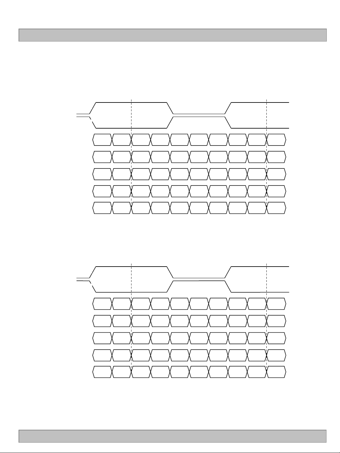
■ LVDS Data-Mapping Information (10 Bit )
1) LVDS Select : “H” Data-Mapping (JEIDA format)
RCLKP
RCLKM
LC550EUF
RAP
RBP
RCP
RDP
REP
R19 R18 R17 R16 G14 R15 R14’ R14 R15’ G14”
B14 G19 G18 G17 B15 G16 G15’ G15 G16’ B15”
V
SYNC HSYNC
B19 B18 DE B17 B16’ B16 B17’ DE”
B13 B12 G13 G12 X R13 R12’ R12 R13’ X”
B11 B10 G11 G10 X R11 R10’ R10 R11’ X”
2) LVDS Select : “L” Data-Mapping (VESA format)
RCLKP
RCLKM
RAP
RBP
R15 R14 R13 R12 G10 R11 R10’ R10 R11’ G10”
B10 G15 G14 G13 B11 G12 G11’ G11 G12’ B15”
Ver. 0.1
RCP
RDP
REP
V
SYNC HSYNC
B15 B14 DE B13 B12’ B12 B13’ DE”
B17 B16 G17 G16 X R17 R16’ R16 R17’ X”
B19 B18 G19 G18 X R19 R18’ R18 R19’ X”
31 /38
Page 33
Product Specification
# APPENDIX- Ill-2
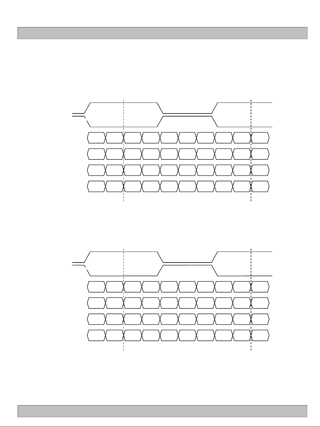
■ LVDS Data-Mapping Information (8 Bit )
1) LVDS Select : “H” Data-Mapping (JEIDA format)
RCLKP
RCLKM
LC550EUF
RAP
RBP
RCP
RDP
R17 R16 R15 R14 G12 R13 R12’ R12 R13’ G12”
B12 G17 G16 G15 B13 G14 G13’ G13 G14’ B13”
V
SYNC HSYNC
B17 B16 DE B15 B14’ B14 B15’ DE”
B11 B10 G11 G10 X R11 R10’ R10 R11’ X”
2) LVDS Select : “L” Data-Mapping (VESA format)
RCLKP
RCLKM
RAP
RBP
R15 R14 R13 R12 G10 R11 R10’ R10 R11’ G10”
B10 G15 G14 G13 B11 G12 G11’ G11 G12’ B15”
Ver. 0.1
RCP
RDP
V
SYNC HSYNC
B15 B14 DE B13 B12’ B12 B13’ DE”
B17 B16 G17 G16 X R17 R16’ R16 R17’ X”
32 /38
Page 34
Product Specification
# APPENDIX- lV
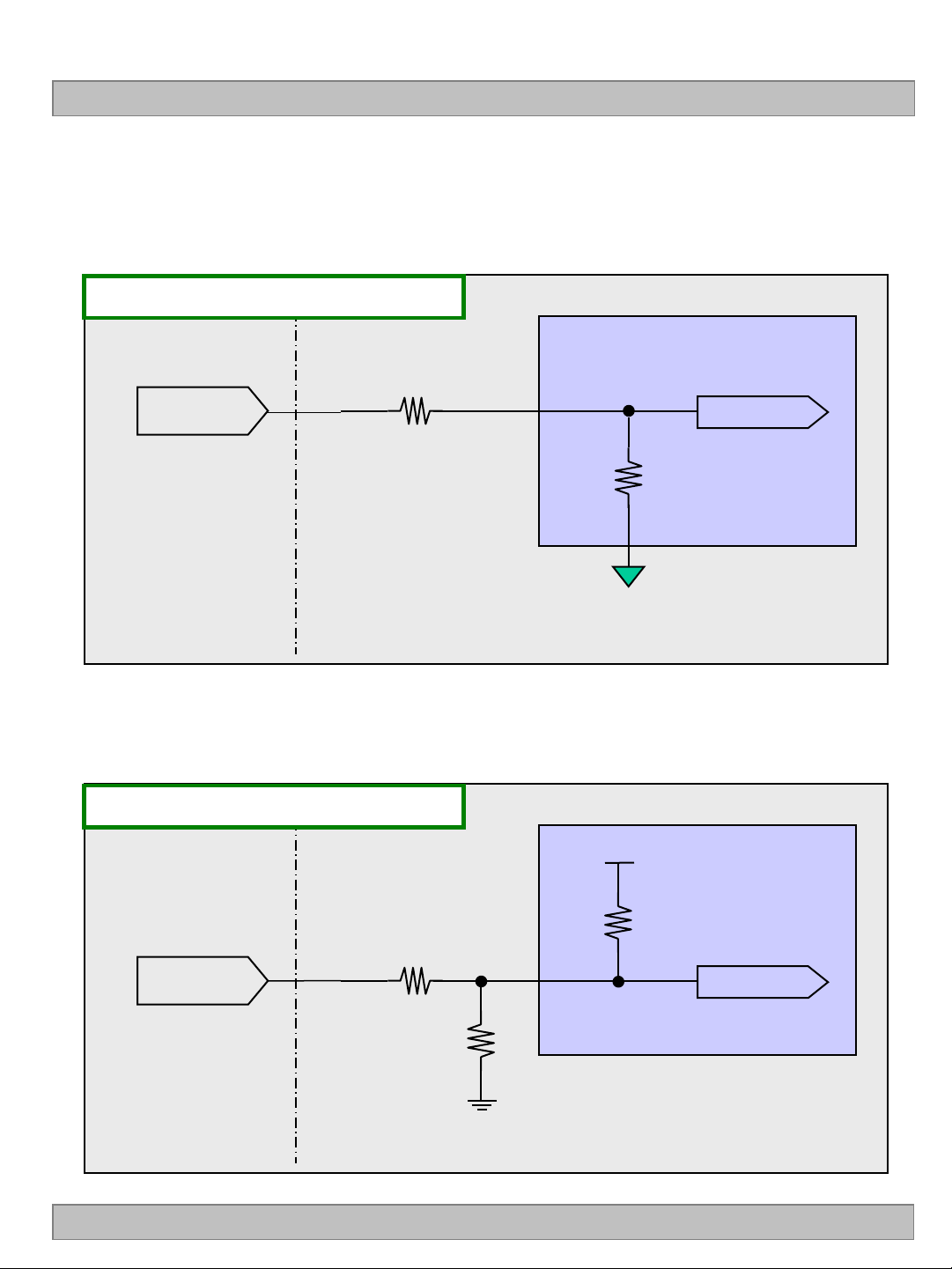
■ Option Pin Circuit Block Diagram
1) Circuit Block Diagram of LVDS Format Selection pin
LVDS Select Pin : Pin 7
1KΩ
LVDS Select
(Pin 7)
60kΩ
ASIC
(TCON)
LVDS Select
LC550EUF
System Side LCM Side
2) Circuit Block Diagram of Bit Selection pin
Bit Select Pin : Pin 27
1KΩ
Bit Select
(Pin 27)
OPEN
System Side LCM Side
65kΩ
VCC
ASIC
(TCON)
Bit Select
Ver. 0.1
33 /38
Page 35
Product Specification
# APPENDIX- V
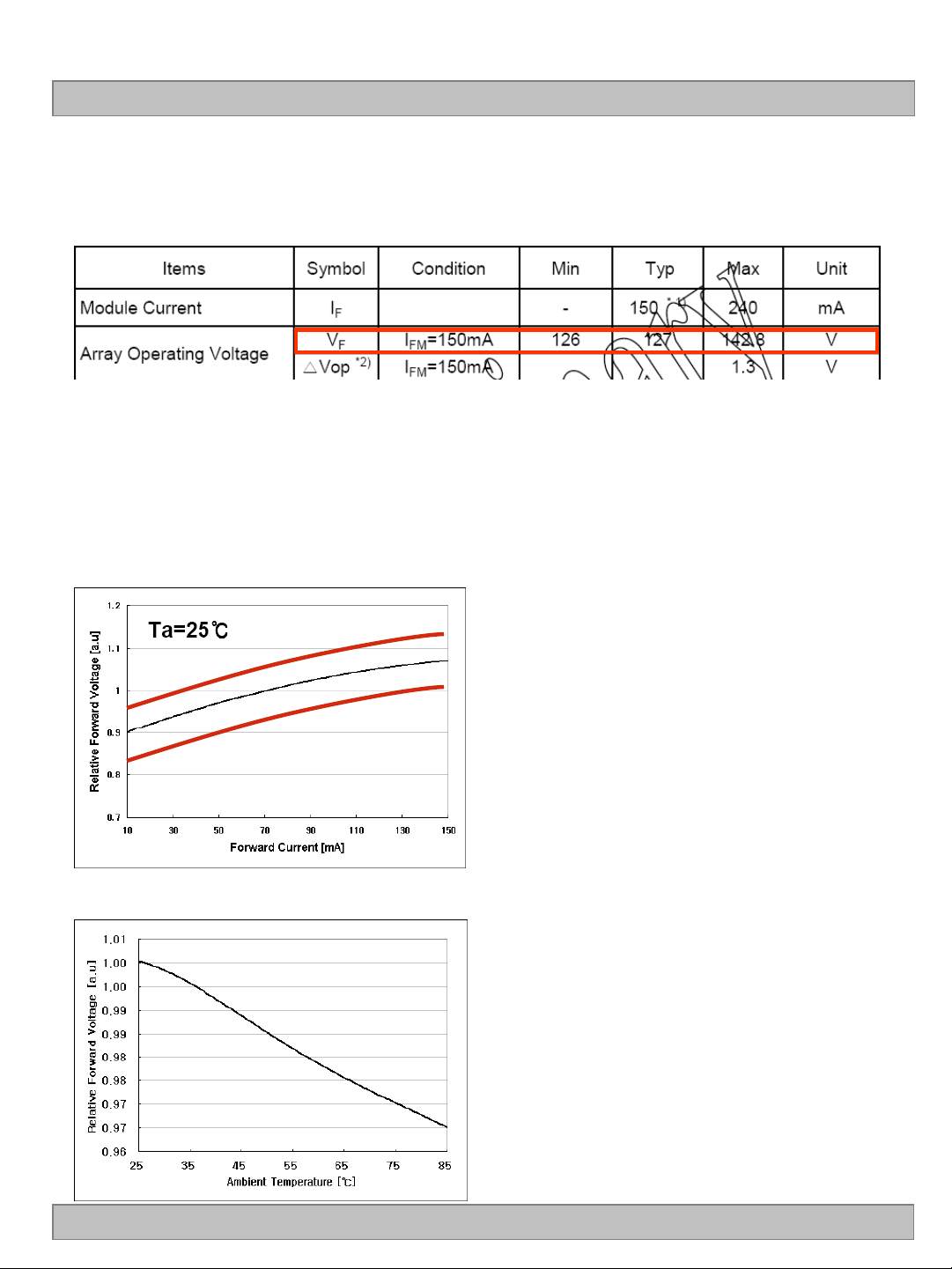
■ LED Array Electrical Spec
■ Forward Current vs. Forward Voltage
LC550EUF
Ta=0℃
Ta=50℃
■ Ambient Temperature vs. Forward Voltage
-20℃
Ver. 0.1
34 /38
Page 36
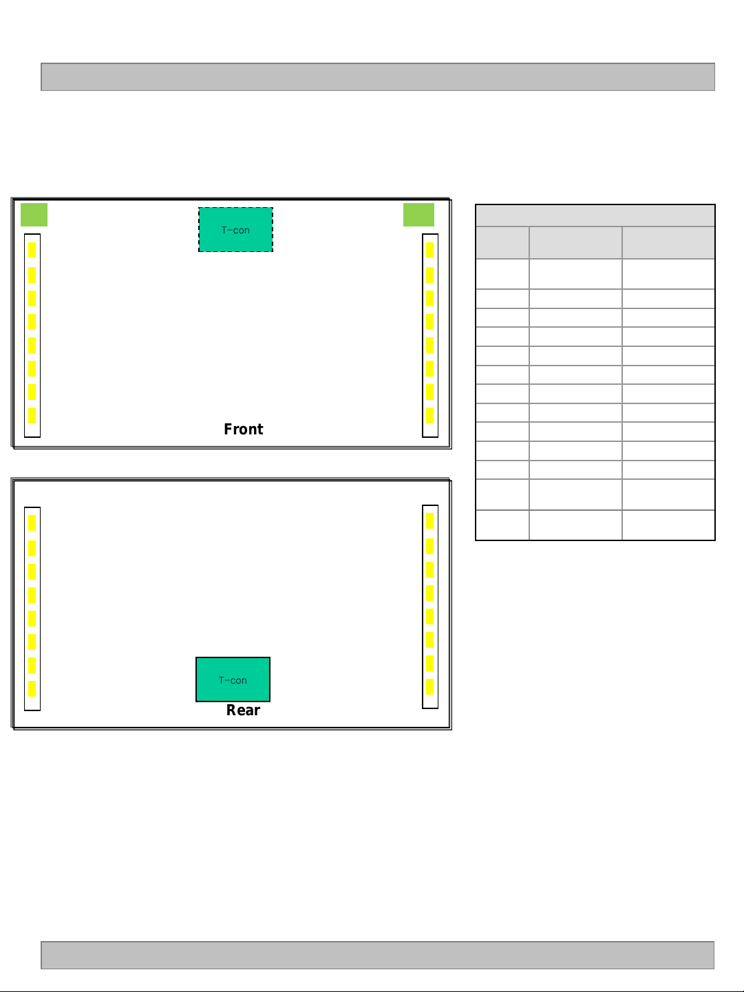
Product Specification
# APPENDIX- Vl
■ Local Dimming Block Pin Matching
LC550EUF
L R
L1
L2
L3
T-con
R1
R2
R3
L5 L4
R5 R4
L7 L6
L8
Front
R7 R6
R8
L8
L7
L6
R8
R7
R6
L4 L5
R4 R5
LED Driver CNT
Pin No CN_201 CN_202
1
2
3
4
5
6
7
8
9
10
11
12
13
Anode_L1
(1~4Cathode)
N.C N.C
L1 Cathode R8Cathode
L2 Cathode R7 Cathode
L3 Cathode R6 Cathode
L4 Cathode R5 Cathode
N.C R4 Cathode
L5 Cathode R3 Cathode
L6 Cathode R2 Cathode
L7 Cathode R1 Cathode
L8 Cathode N.C
N.C
Anode_L2
(5~8Cathode)
Anode_R2
(5~8Cathode)
Anode_R1
(1~4Cathode)
-
L2 L3
L1
Ver. 0.1
T-con
Rear
R2 R3
R1
35 /38
Page 37
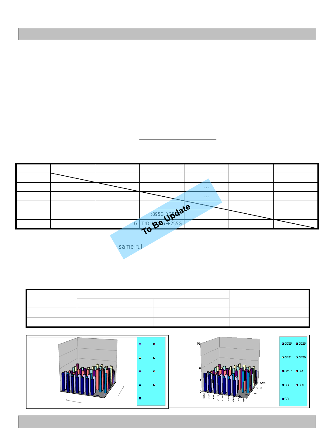
LC550EUF
G255
G223
G191
G159
G127
G95
G63
G31
G0
G255
G159
G63
0
4
8
12
16
G255 G223
G191 G159
G127 G95
G63 G31
G0
Tr
Tf
)(
)()(
GtoGTypical
GtoGTypicalGtoGMaximum
Product Specification
# APPENDIX- VIl-1
Gray to Gray Response Time Uniformity
This is only the reference data of G to G and uniformity for LC550EUF-LDC1 model.
1. G to G Response Time :
Response time is defined as Figure3 and shall be measured by switching the input signal for
“Gray (N) ” and “Gray(M)”.(32Gray Step at 8bit)
2. G to G Uniformity
The variation of G to G Uniformity , G to G is defined as :
G to G Uniformity =
*Maximum (GtoG) means maximum value of measured time (N, M = 0 (Black) ~ 1023(White), 128 gray step).
0Gray
127Gray
255Gray
…
895Gray
1023Gray
0Gray 127ray 255Gray … 895Gray 1023Gray
TrR:0G127G TrR:0G255G … TrR:0G895G TrR:0G1023G
TrD:127G0G TrR:127G255G … TrR:127G895G TrR:127G1023G
TrD:255G0G TrD:255G127G … TrR:255G895G TrR:255G1023G
… … … … …
TrD:895G0G TrD:895G127G TrD:895G255G … TrR:895G1023G
TrD:1023G0G TrD:1023G127G TrD:1023G255G … TrD:1023G895G
3. Sampling Size : 2 pcs
4. Measurement Method : Follow the same rule as optical characteristics measurement.
≤1
5. Current Status
Below table is actual data of production on TBD ( L&T SVT Event Sample)
G to G Response Time [ms]
Min. Max.
Ver. 0.1
# 1
# 2
< # 1 > < # 2 >
TBD TBD TBD
TBD TBD TBD
Uniformity
36 /38
Page 38
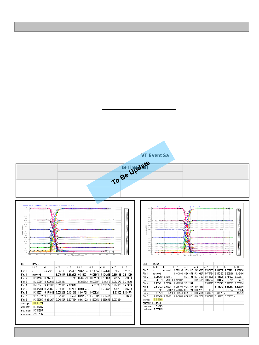
# APPENDIX- VIl-2
LC550EUF
Product Specification
■ MPRT Response Time Uniformity (
MPRT
)
This is only the reference data of MPRT and uniformity for LC550EUF-LDC1 model.
1. MPRT Response Time :
Response time is defined as Figure3
2. MPRT Uniformity
The variation of MPRT Uniformity , MPRT is defined as :
MPRT Uniformity =
Maximum (MPRT) - Typical (MPRT)
Typical (MPRT)
≤1
3. Sampling Size : 2 pcs
4. Measurement Method : Follow the same rule as optical characteristics measurement.
5. Current Status
Below table is actual data of production on TBD ( L&T SVT Event Sample)
Sample
# 1 TBD TBD TBD
# 2 TBD TBD TBD
MPRT Response Time [ms]
Min. Max.
Uniformity
Ver. 0.1
37 /38
Page 39
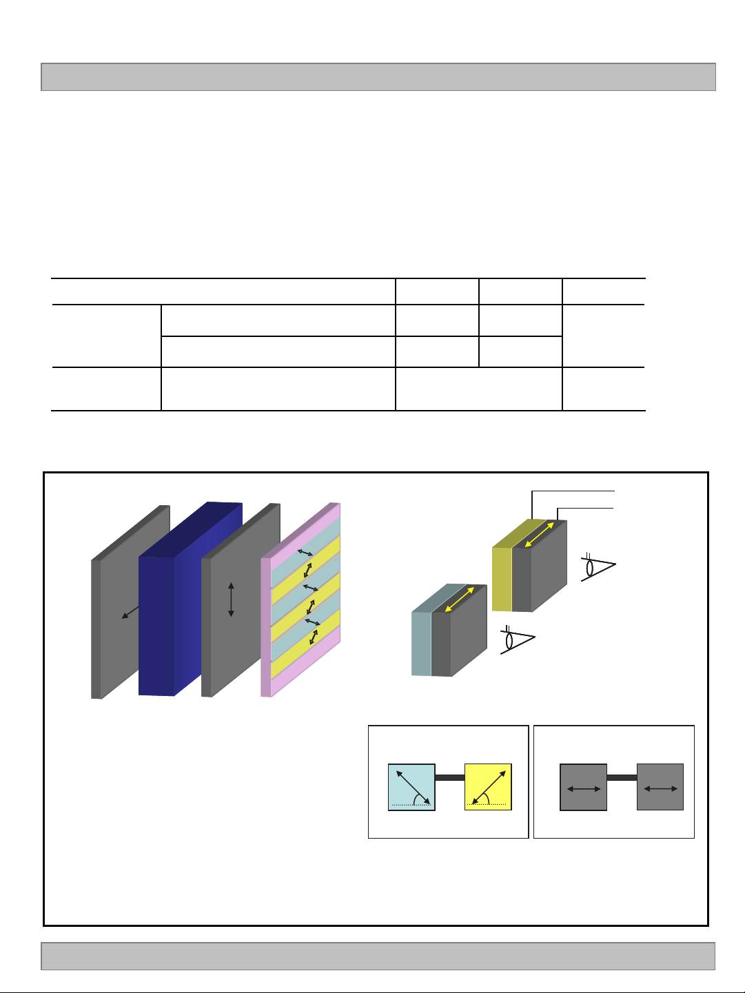
Product Specification
Polarizer
Retarder
Right eye
Left eye
+λ /4
-λ /4
Polarizer
Retarder
Right eyeRight eye
Left eyeLeft eye
+λ /4
-λ /4
a) Slow axis of retarder
Left Right
45˚
-45˚
a) Slow axis of retarder
Left Right
45˚
-45˚
b) Transmission axis of polarizer
Left Right
0˚
0˚
b) Transmission axis of polarizer
Left Right
0˚
0˚
0˚
90˚
45˚
135˚
Cell Patterned
retarder
Top
POL
Bottom
POL
0˚0˚
90˚90˚
45˚
135˚
45˚
135˚
Cell Patterned
retarder
Top
POL
Bottom
POL
# APPENDIX- Vlll
■ Standard specification of Eyeglasses
This is recommended data of Eyeglasses for LC550EUF-LDC1 model. (details refer to table)
For each item, depending on the eyeglass manufacturer tolerances may occur, this tolerance can
affect 3D performance. (3D Crosstalk, 3D luminance, 3D viewing angle)
<Table. Standard specification of Eyeglasses>
Design item of Eyeglasses Left Right Remark
LC550EUF
Optical
axis
Retardation
value
a) Slow axis of retarder
b) Transmission axis of polarizer
Retarder 125nm @550nm
※Recommended polarizer
Polarization efficiency: more than 99.90%
45
-45
135
45 ˚ 45
Patterned
Patterned
retarder
retarder
-45˚ 45˚
0˚ 0˚
˚
˚
˚
˚
Refer to
drawing
Direction from viewer
Ver. 0.1
(b) Configuration of Eyeglasses
<Drawing. Information of optical axis>
38 /38
 Loading...