

Page 1

Room Air Conditioner
SVC MANUAL(Exploded View)
MODEL : TS-C1825DA1
CAUTION
Before Servicing the unit, read the safety precautions in General SVC manual.
Only for authorized service personnel.
http://biz.lgservice.com
Page 2
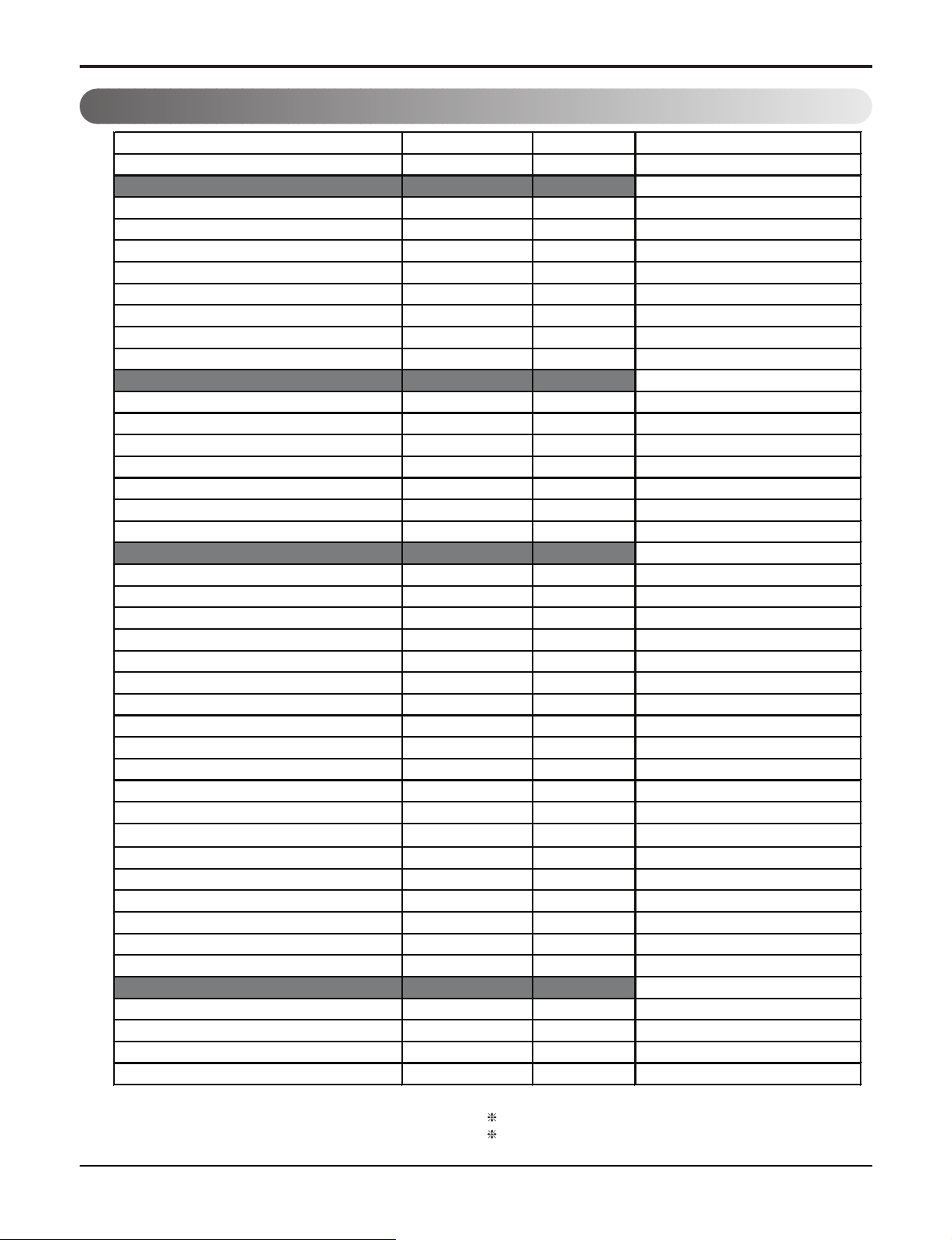
1. Specification
Product Model TS-C1825DA1
Sales Model SJ182CD
Capacity
Cooling Capacity
Btu/h
18000
Heating Capacity
Btu/h
-
Electrical Parts
Voltage. Frequency/Phase
Φ / V / Hz
1,220V,60Hz
Power Input Cooling W
1800
Heating W
-
Running Current Cooling A
8.4
Heating A
-
Performance
EER Cooling
Btu/h
10.0
COP Heating
W/W
-
Air Circulation
Indoor,Max
㎥
/min(cfm)
13.0
Outdoor,Max
㎥
/min(cfm)
28
Moisture Removal l/h
2.5
Sound Level
Indoor,H/M/L dB(A)+3
42
Outdoor,Max dB(A)+3
56
Feature
Neo Plasma Air Purifying System
N
Anti Corrasion
N
Temperature Control
Y
CHAOS Wind(Auto Wind)
N
Airflow Direction Control(up&down)
Auto
Airflow Direction Control(left&right)
Manual
Remocon Type
Wireless Simple
Setting Temperature Range Cooling
18-30
Heating
-
Auto Chage Over
N
Auto Clean
N
Seps,Fan/Cool
3/4
Temperature Increment
1oC
Timer
7Hr,Off
Sleep Operation
Y
Restart Delay(Minute)
3
Hot start
-
Jet Cool
Y
Compressor Type
Rotary,PH250(Toshiba)
Installation & Stuffing
Net Dimensions WxHxD mm
1090*314*190/770*540*245
Net Weight Indoor/Outdoor kg
14/41
Q'ty With S/parts 20/40FT
Without S/parts 20/40FT
Note:
O
: Applied, - : No relation
*
For circuit breaker rating, please conform to local standards wherever necessary.
2 Room Air Conditioner
Some of functions are slightly different depending upon models.
The specification may be subject to change without prior notice for purpose of
improvement.
Page 3
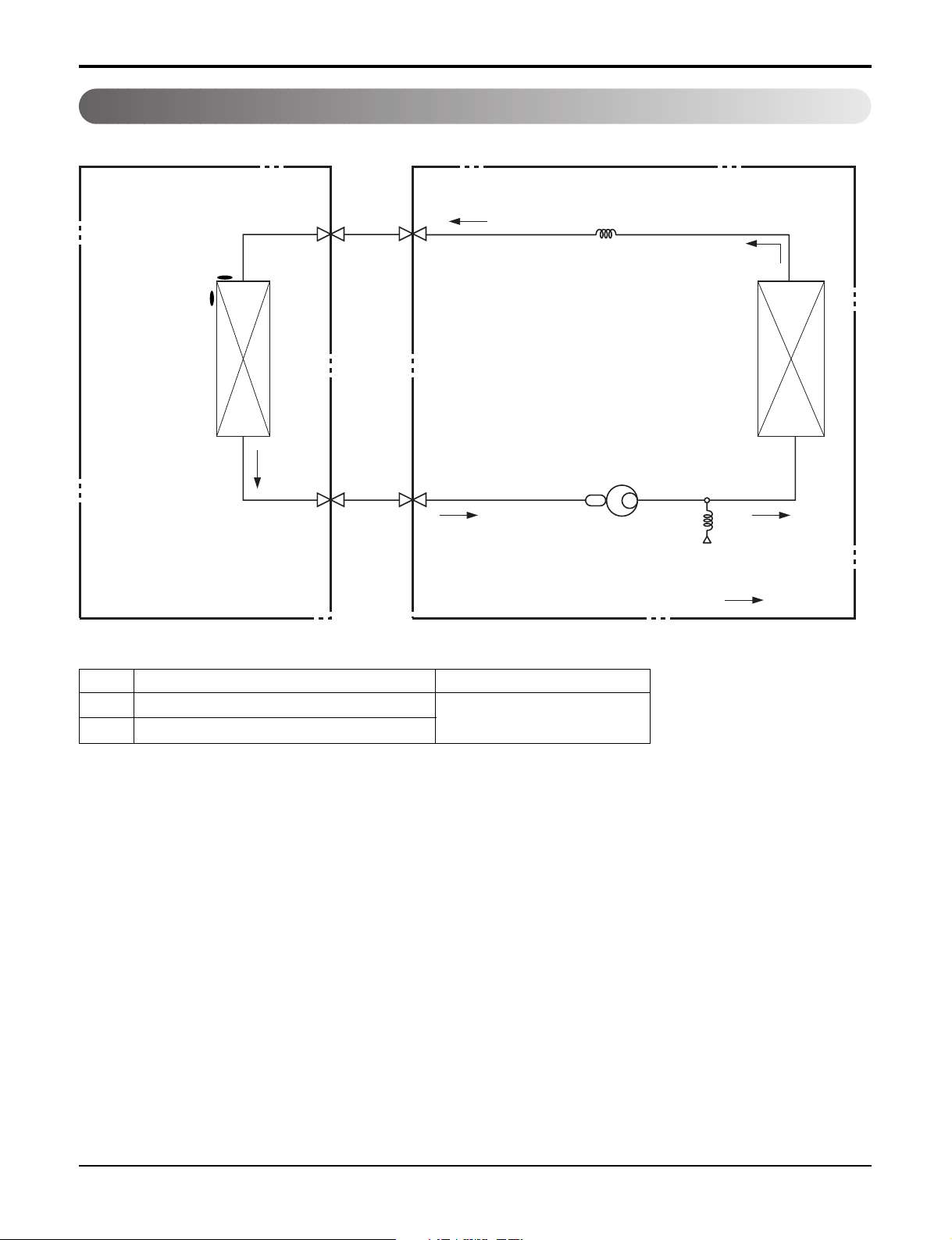
2. Piping Diagrams
Indoor Unit Outdoor Unit
Th1
Heat
Exchanger
(Evaporator)
Th2
Liquid Side
2-Way Valve
Gas Side
3-Way Valve
Capillary Tube
Heat
Exchanger
(Condenser)
Compressor
Accumulator
High Pressure S/W
Cooling
LOC. Description PCB Connector
Th1 Thermistor for indoor air temperature
Th2 Thermistor for evaporating temperature
CN-TH1
Service Manual 3
Page 4

3. Wiring Diagrams
Indoor Unit
BL
BR
1(L)2(N)
YL
/
GN
3
FUSE
CN-N2
CN-N1
CN-MOTOR
YL
/
BL
BR
GN
RY-COMP
RY-COMP4
CN-U/D
3854A23009
CN-HVB
CN-DISP2
4 Room Air Conditioner
Page 5

Service Manual 5
Outdoor Unit
BLUE
R
OVERLOAD
PROTECT
C
TERMINAL BLOCK
RED
S
WN
E
O
U
BR
BL
1(L)
2(N)
BLUE
BROWN
THE UNIT INDOOR
H
BLUE
/GREEN
YELLOW
OUTDOOR DIAGRAM WIRING
CAPACITOR
C
F
BLUE
RED
EBY36312302
FAN
YELLOW
Capacitor
Terminal Block
Page 6

Exploded View
Exploded View
6 Room Air Conditioner
1. Indoor Unit
135313
342800
359011
131410 733010
135316
135311
147581
268711A
146811
346810
W0CZZ
135516
35211B
354210
249951267110
352116
352115
152302
268711D
352150
Page 7

Service Manual 7
Outdoor Unit
Exploded View
Exploded View
435512
554031
437212
552112
552111
649950
549610
435511
559010
546810
435301
447910
437210
554160
552203-1
550140
430410
552203-2
Page 8

P/NO : MFL37322726
JANUARY, 2008
 Loading...