

Page 1

Room Air Conditioner
SVC MANUAL(Exploded View)
MODEL : TS-C122YDA0
CAUTION
Before Servicing the unit, read the safety precautions in General SVC manual.
Only for authorized service personnel.
http://biz.lgservice.com
Page 2
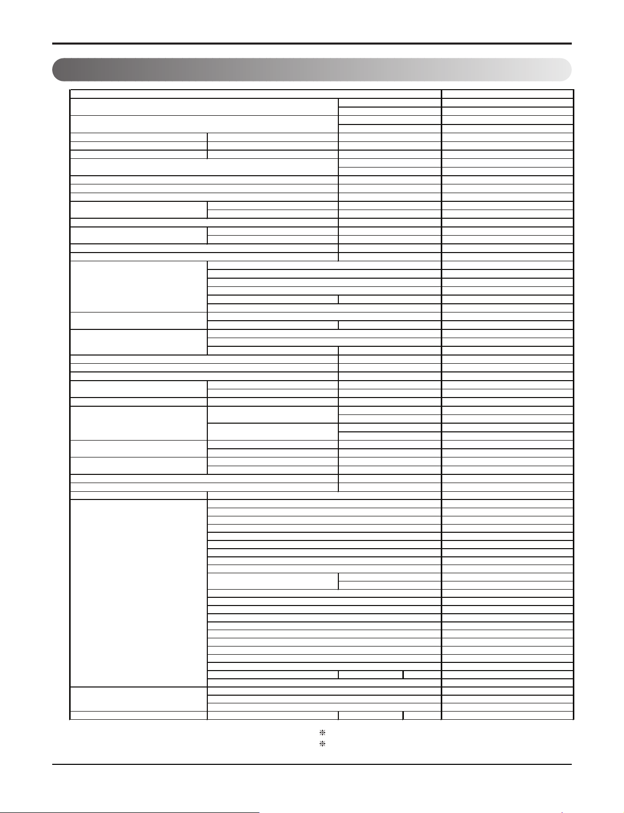
1. Specification
TS -C1 2 2 YDA0
3.52
12,000
-
-
Power Input
Cooling/Heating 1 150/-
Running Current
Cooling/Heating 5.4/-
Starting Current
Cooling/Heating 26/-
3.05
10.43
-
1/220/60
99.3
Indoor,Max
8.83
Outdoor,Max 18
1.46
Indoor,H/M/L 41
Outdoor,Max
51
R22, 650(22.92)
20(0.22)
Rotary(Non Tropical)
PH180X1C-3FTU2
PSC
SUNISO 4GSI
Oil Charge
400 cc
-
Cross Flow Fan
Motor Output 46
Propeller
AC Induction
Motor Output 89
29
3*1.0
-
Liquid Side
6.35(1/4)
Gas Side
12.7(1/2)
Drain Hose O.D , I.D 21.5,16(0.85,0.63)
902*322*200
35.5*12.68*7.87
770*540*2450
30.31*21.26*9.65
Indoor 9(19.8)
Outdoor 35(77.1)
Cooling(Outdoor)
21 ∼ 43
Heating(Outdoor)
-
13
7.5
Tool Code(Chassis) SY + UL
Indoor + Outdoor
Max. Piping Length
m(ft)
Max. Elevation Difference
m(ft)
Operation Range
oC(o
F)
oC(o
F)
inch
Net Weight
kg(lbs)
kg(lbs)
mm(in)
Dimension
Indoor(W*H*D)
mm
inch
Outdoor(W*H*D)
Power and Transmission Cable
No.*㎟+No.*
㎟
Piping
Connections
mm(in)
mm(in)
Circuit Breaker
*
A
Power Supply Cable
No.*
㎟
Fan(outdoor)
Type
Motor Type
W
Fan(Indoor)
Type
W
Compressor
Type
Model
Motor Type
Oil Type
cc
O.L.P Name
Refrigerant & Charge(at 7.5m)
g(oz)
Additional Refrigerant Charge
g/m(oz/ft)
Moisture Removal
l/h
Sound Level
dB(A)+1
dB(A)+1
Power Factor
%
Air Flow Rate
㎥
/min(cfm)
㎥
/min(cfm)
COP
W/W
Power Supply
Φ / V / Hz
A
EER
W/W
Btu/h.W
W
A
Heating Capacity
(Min∼Rating∼Max)
kW
Btu/h
Models
Cooling Capacity
(Min∼Rating∼Max)
kW
Btu/h
Thermistor
○
○
-
○
3/4/-
Auto
Manual
Wireless Simple
18 ∼ 30
-
-
-
○
7h, On/Off
○
○
3
○
-
○
Low Ambient Operation -
-
-
-
-
Note:
Special Function
Network Functions
Dry Contact
Network Solution(LGAP)
PI485
Functions
Hot Start
Jet Cool
Restart Delay(minute)
Deice Control(Defrost)
Sleep Operation
Soft Dry Operation
Self Diagnosis
Timer
Auto Operation (Micom Control)
Auto Changeover (Micom Control)
Remocon Type
Setting Temperature
Range
Cooling
Heating
Auto Clean
Airflow Direction Control(up&down)
Airflow Direction Control(left&right)
CHAOS Wind(Auto Wind)
Steps, Fan/Cool/Heat
Temperature Control
Plasma Filter
Prefilter(washable/anti-fungus)
Note:
O
: Applied, - : No relation
*
For circuit breaker rating, please conform to local standards wherever necessary.
2 Room Air Conditioner
Some of functions are slightly different depending upon models.
The specification may be subject to change without prior notice for purpose of
improvement.
Page 3
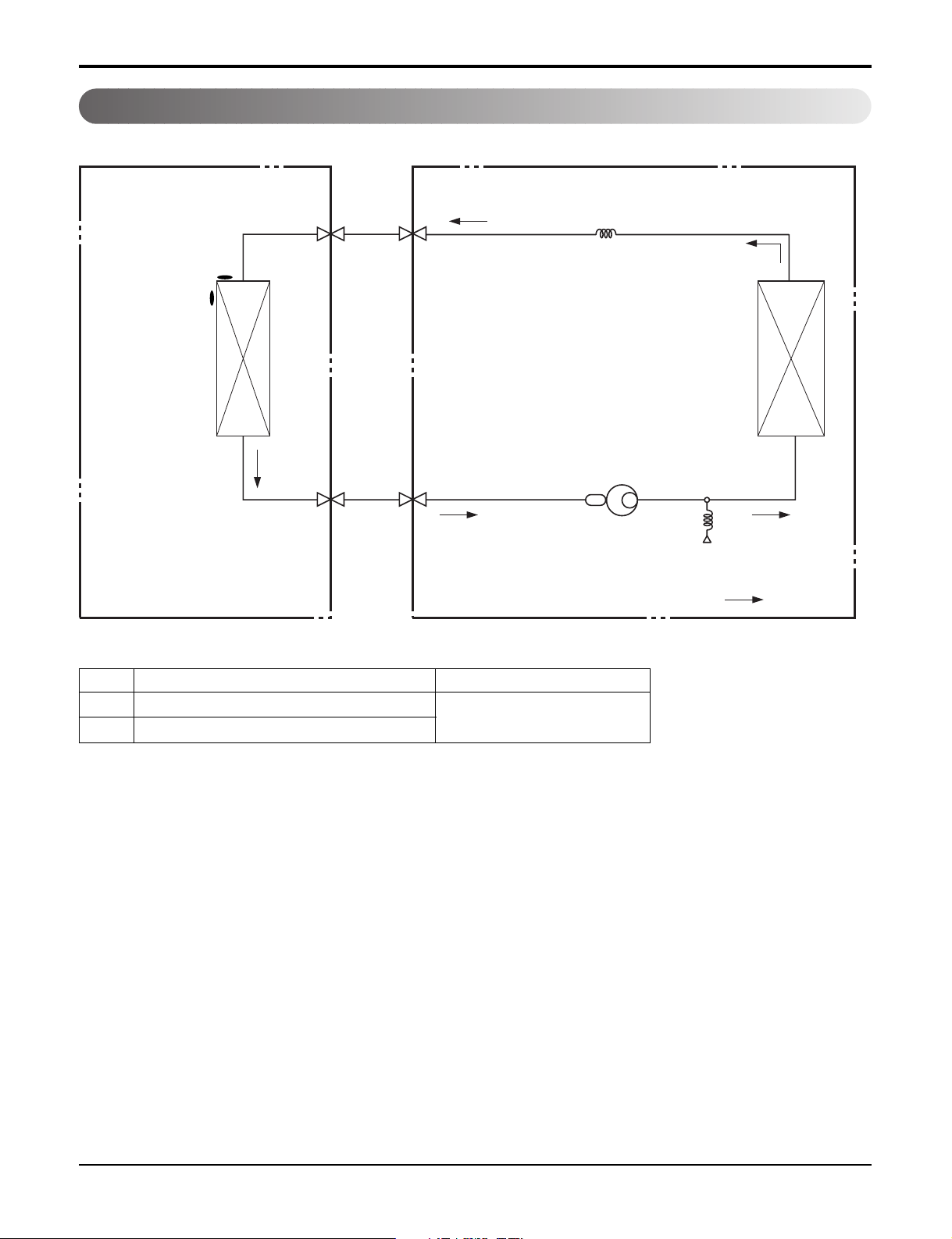
2. Piping Diagrams
Indoor Unit Outdoor Unit
Th1
Heat
Exchanger
(Evaporator)
Th2
Liquid Side
2-Way Valve
Gas Side
3-Way Valve
Capillary Tube
Heat
Exchanger
(Condenser)
Compressor
Accumulator
High Pressure S/W
Cooling
LOC. Description PCB Connector
Th1 Thermistor for indoor air temperature
Th2 Thermistor for evaporating temperature
CN-TH1
Service Manual 3
Page 4

3. Wiring Diagrams
Indoor Unit
BL
BR
1(L)2(N)
YL
/
GN
3
CN-N2
CN-N1
CN-MOTOR
FUSE
BR
YL
/
BL
GN
RY-COMP3
RY-COMP4
3854A23009
CN-HVB
CN-U/D
CN-DISP2
4 Room Air Conditioner
Page 5

Service Manual 5
Outdoor Unit
BLUE
R
OVERLOAD
PROTECT
C
TERMINAL BLOCK
RED
S
WN
E
O
U
BR
BL
1(L)
2(N)
BLUE
BROWN
THE UNIT INDOOR
H
BLUE
/GREEN
YELLOW
OUTDOOR DIAGRAM WIRING
CAPACITOR
C
F
BLUE
RED
EBY36312302
FAN
YELLOW
Capacitor
Terminal Block
Page 6

Exploded View
1. Indoor Unit
135316
135314
152302
131410
135301
3
1
W3300
Exploded View
1
1
5
5
435301
147581-1
268711
135311
354210
147582-1
147582-2
342800
359011
146811
35211B
352150
346810
135516
354212
263230
249941
264110
267110
6 Room Air Conditioner
249951
WOFZZ
268711
W6640
W0CZZ
Page 7

Outdoor Unit
435511
437212
559010
W0CZZ
W6640
649950
552203-2
437211
552203-1
447910
554032
550140
148000
Models:TS-C122YDA0
237202
435301
349600
546810
552111
567502
554160
552117
W6631
430400
430410
Service Manual 7
Page 8

P/NO : MFL37322726
DECEMBER, 2008
 Loading...