

LG TD-V10056G Owner's manual [es]
conservesumanualparafuturas.referencias .mantenimientoGuardeelmodeloynùmerodeseriey informaciònimportantedeunainstalaciònsegura,Usoy Porfavorleasumanualcorrectamente,yaquecontiene GraciasporcomprarunaSecadora.LG
TD-V14056E/TD-V14056G TD-V12056E/TD-V12056G TD-V12055E/TD-V12055G TD-V10051E/TD-V10051G TD-V10055E/TD-V10055G TD-V10050E/TD-V10050G

TD-V10050E/TD-V10050G TD-V10055E/TD-V10055G TD-V10051E/TD-V10051G TD-V12055E/ TD-V12055G TD-V12056E/ TD-V12056G TD-V14056E/TD-V14056G
Thank you for buying a LG Dryer.
Please read your manual carefully,as it provides instructions on safe Installation,Use and Maintenance. Record the Model and Serial Numbers,and retain the manual for future reference.
P/No.: 3828EL3003F

PRODUCT FEATURES
1
2
3
4
5
OUTSTANDING PERFORMANCE
Not to mention unmatched big capacity, you can benefit from good time efficiency, quiet operation and energy saving system.
STAINLESS STEEL DRUM
The Drum is coated with both a metal and a polymer coating in order to guarantee high durability and long life.
ARTISTIC DESIGN
Modern front panel look and big crystal-clear glass door make your house look stylish.
DIGITAL FABRIC CARE
Multi-Level temperature control takes better care of your clothes
EASY OF USE
An entire selection of user-friendly functions make operating the dryer easy.
TABLE OF CONTENTS |
|
PART1. SPECIFICATIONS ..................................................................................................................................... |
3 |
PART2. IMPORTANT WARRANTY AND SAFETY INSTRUCTIONS ................................................................. |
4-6 |
PART3. INITIAL STEPS FOR INSTALLING YOUR DRYER ............................................................................. |
7-12 |
PART4. ACCESSORIES INSTALLATION ....................................................................................................... |
13-14 |
PART5. ELECTRICAL REQUIREMENTS FOR ELECTRIC DRYER ............................................................... |
15-18 |
PART6. ELECTRICAL REQUIREMENTS FOR GAS DRYERS ............................................................................ |
19 |
PART7. GAS REQUIREMENTS AND INSTRUCTIONS........................................................................................ |
20 |
PART8. EXHAUST REQUIREMENTS AND MAINTENANCE.......................................................................... |
21-22 |
PART9. OPERATING YOUR DRYER............................................................................................................... |
23-28 |
PART10. TROUBLESHOOTING GUIDE .......................................................................................................... |
29-31 |
2
Part 1 SPECIFICATIONS
|
|
|
|
|
|
|
|
|
|
|
|
|
|
|
|
|
|
|
|
|
|
|
|
|
|
|
|
|
|
|
|
|
|
|
|
|
|
|
|
■ Name |
: Electric and Gas Dryer |
||||||||
■ Power supply |
: Please refer to the rating label regarding detailed |
||||||||
|
|
|
information. |
||||||
■ Size |
: 27 x 29.9 x 38.7 (inch) |
||||||||
■ Dryer capacity |
: Refer to Rating Label |
||||||||
■ Weight |
: 126(Ibs) |
||||||||
Specifications are subject to change by manufacturer.
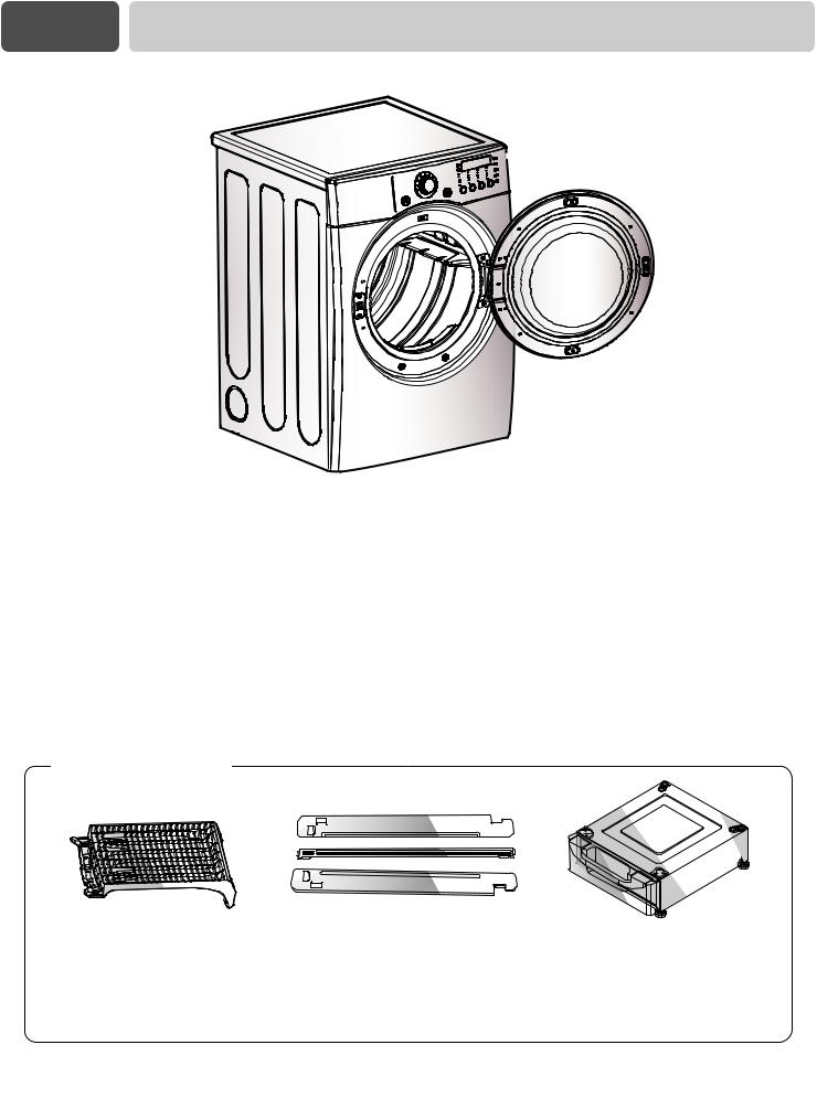
■ ACCESSORIES
|
|
|
|
|
|
|
|
|
|
|
|
|
|
|
|
|
|
|
|
|
|
|
|
|
|
|
|
|
|
|
|
|
|
|
|
|
|
|
|
|
|
|
|
|
|
|
|
|
|
|
|
|
|
|
|
|
|
|
|
|
|
|
|
|
|
|
|
|
|
|
|
|
|
|
|
|
|
|
|
|
|
|
|
|
|
|
|
|
|
|
|
|
|
|
|
|
|
|
|
|
|
|
|
|
|
|
|
|
|
|
|
|
|
|
|
|
|
|
|
|
|
|
|
|
|
|
|
|
|
|
|
|
|
|
|
|
|
|
|
|
|
|
|
|
|
|
|
|
|
|
|
|
|
|
|
|
|
|
|
|
|
|
|
|
|
|
|
|
|
|
|
|
|
|
|
|
|
|
|
|
|
|
|
|
|
|
|
|
|
|
|
Dryer rack (1 each) |
|
|
|
|
|
|
Stacking kit (1 each) |
|
|
|
|
|
Pedestal (1 each) |
|
|
|
|
|
|
|
|
|
|
|
Purchased Separately |
|
|
|
|
|
Purchased Separately |
|
|
||
|
|
|
||||||||||||||||
|
|
|
|
|
|
|
|
|
|
|
|
|
|
|
|
|
|
|
|
|
|
|
|
|
|
|
|
|
|
|
|
|
|
|
|
|
|
|
|
|
|
|
|
|
|
|
|
|
|
|
|
|
|
|
|
|
|
See page 26 for how to use. |
|
|
|
|
See page 13 for how to use. |
|
See page 14 for how to use. |
||||||||||
|
|
|
|
|
|
|
|
|
|
|
|
|
|
|
|
|
|
|
3

IMPORTANT WARRANTY AND SAFETY INSTRUCTIONS
SEEKING WARRANTY ASSISTANCE
The Warranty for your Dryer is located at the end of this manual.Warranty Service is available by contacting your nearest LG Service Center. If this product is installed and operated per this manual, LG will repair or replace any parts defective in material or workmanship throughout the Warranty period, beginning the Date of Purchase.
!WARNING!
For your safety, the recommendations in this manual must be followed. To reduce the risk of fire or explosion, electric shock, or to prevent property damage, personal injury, or death when using your appliance, follow basic precautions, including the following.
Warranty Restriction: If the dryer is subjected to other than private family use, all warranty coverage is effective for only 90 days.
You will need the complete Model and Serial Number when requesting Warranty Service. Proof of purchase date is required.
Use the space below to record the model number and serial number of your new LG dryer.
Model No.
Serial No.
Date of Purchase
Staple your receipt HERE.
4

Part 2 IMPORTANT WARRANTY AND SAFETY INSTRUCTIONS
IMPORTANT SAFETY INSTRUCTIONS
!WARNING!
To help reduce any risk of electric shock, fire, or other personal or property injury when using your dryer, please exercise care and follow basic safety precautions, including the following:
SAVE THESE INSTRUCTIONS
codes and ordinances.
WARNING - Improper connection of the equipmentgrounding conductor can result in a risk of electric shock. Check with a qualified electrician or service person if you are in doubt as to whether the appliance is properly grounded.
5

IMPORTANT WARRANTY AND SAFETY INSTRUCTIONS
!WHAT TO DO IF YOU SMELL GAS:
•Do not try to light a match or cigarette, or turn on any gas or electrical appliance.
•Do not touch any electrical switches. Do not use any phone in your building.
•Clear the room, building or area of all occupants.
•Immediately call your gas supplier from a neighbor’s phone. Follow the gas supplier’s instructions carefully.
•If you cannot reach your gas supplier, call the fire department.
!WARNING
To reduce the risk of fire or explosion, electric shock, property damage, personal injury or death when using this appliance, please follow all instructions and information, including those in this manual and instructions and information provided by your gas supplier, including the following:
•Do not store or use any gasoline, dry-cleaning solvents any other flammable vapors or liquids in the area surrounding this appliance.
•Do not dry anything that has ever had anything flammable on it, even after washing.
•No washer can completely remove oil. Do not dry any articles that have ever had any kind of oil on them, including cooking oil.
•Articles containing foam, rubber, rubber-like materials, plastic or similar materials should be dried on a clothesline or by using an air cycle.
•Failure to follow these instructions can result in fire, death or serious injury.
•A qualified service person or company must perform installation and service of this appliance.
!WARNING!
•Keep flammable materials and vapors, such as gasoline, away from dryer.
•Place dryer at least 18 inches above the floor for a garage installation.
•Failure to do so can result in death, explosion or fire.
6

Part 3 INITIAL STEPS FOR INSTALLING YOUR DRYER
through the initial steps of setting up your dryer for use. provides important information regarding the preparation and review this entire manual before proceeding with any
concerning electrical connections, gas connections, and of this manual.


 STEP 1 Positioning the Dryer.
Choose a location with a solid floor for your dryer. Place the dryer at least eighteen inches above the floor for a garage installation. After placing the dryer in the desired location, please make sure that it has the required clearances shown below, and sections on Exhaust and Maintenance requirements. If you are installing your dryer in a manufactured or mobile home, please refer to STEP 9 below for additional instructions.
49.8” (126.4 cm)
38.7” (98.3 cm)
27” |
29.9” |
(68.6 cm) |
(76.1 cm) |
Certain minimum clearances are required above, behind,and to the sides of the unit,as shown below. Those required minimum clearances are set forth in the picture below. Please also keep the following instructions in mind when installing in a closet or recessed area:
•Consider allowing additional clearance for installation and servicing.
•Wall,door and floor molding may forceadditional clearances.
•An additional inch of clearance is recommended to minimize noise transfer
•Consider space needed for companion appliances.
•For closet installations, the picture below shows the minimum required ventilation openings for the door. A louvered door with comparable ventilation openings is also acceptable.
ventilation |
hole |
ventilation |
hole |
<Closet door>
<Closet-Side view> |
*Most installations require a minimum 5 1/2 in.
(14 cm) clearance behind the dryer for the exhaust vent with elbow.
<Closet-Front view>
7

Part 3 INITIAL STEPS FOR INSTALLING YOUR DRYER
Once in position, adjust the leveling legs of the dryer until it is level from left to right and from front to back. The leveling legs must remain firmly on the floor and the dryer should not rock. The maximum slope of the dryer from left to right or from front to back should not exceed 2.5 cm (1 inch). If the dryer
STEP 2 Procedure for Reversing the Door
The door on your dryer can be installed to open either to the left or the right. Follow these procedures to reverse the direction in which your door opens:


 1
1


 2
2


 3
3


INSTALLING YOUR DRYER
STEP 3 Connecting the Exhaust
and Venting System.
In addition to the following warnings, please refer to manual section on Exhaust Requirements and Maintenance. IMPORTANT: To reduce the risk of fire, combustion, and gas accumulation, the dryer must be vented to the outdoors. Please follow the instructions (and all others in this manual) very carefully.
•Do not use thin plastic or foil ducting.
•Use 4" (10.2 cm) diameter rigid or flexible metal duct (note: venting materials are not supplied with the dryer, and you should obtain the venting materials necessary for proper installation)
•Position the Dryer such that the exhaust duct run is as short as possible.
•Clean old ducts before installing this dryer
•The male end of each section of exhaust duct must point away from the dryer
•Use as few elbow joints as possible.
•Use duct tape on all duct joints
•Insulate ductwork that runs through unheated areas in order to reduce condensation and lint build-up on pipe walls; and
•PLEASE BE AWARE THAT FAILURE TO EXHAUST THE DRYER CORRECTLY WILL VOID THE DRYER’S WARRANTY.
!WARNING!
•Use a heavy metal vent.
•Do not use a plastic vent.
•Do not use a metal foil vent.
•Failure to follow these instructions can result in death or fire.
•Clean old ducts before installing this dryer
■ALTERNATE EXHAUST DIRECTIONS
1.Remove a screw and exhaust duct.
2-1. Detach and remove the knockout that matches the desired venting direction (Right side not available on Gas Dryers)  ,
,  ,
,  the order of work.
2-2. Reconnect the duct to the blower housing and attach the duct to the base.(Duct is a SVC part)
3-1. Pre-assemble 4" elbow with 4" duct. Wrap duct tape around joint.
3-2. Insert elbow duct assembly first through the side opening and connect the elbow to the internal duct.
9


 STEP 4 Connection of Gas Supply


(Gas dryer only). In addition to the following, please refer to manual section on Gas Requirements and Instructions.
 1
1


 2
2
5

 3
3  4
4
1.New stainless steel flexible connector. Use this type of connector only if allowed by local codes. Use Design AGA Certified Connector.
2.1/8" NPT Pipe Plug (for checking inlet gas pressure)
3.Equipment Shut-Off ValveInstalled within 6’ (1.8 m) of dryer
4.Iron Pipe. Shorter than 20’ (6.1 m)
Use 3/8" pipe. Longer than 20’ (6.1 m) - Use 1/2" pipe.
5.3/8" N.P.T. Gas Connection
1.Confirm that the type of gas available in your laundry room is appropriate for the dryer. The dryer is prepared for Natural Gas with a 3/8"
NPT gas connection.
2.Remove the shipping cap from the gas connection at the back of the dryer. Make sure that you don’t damage the threads of the gas connection pipe when you remove the shipping cap.
3.Connect the dryer to your laundry room’s gas supply using a new flexible stainless steel connector (as noted below, only use a new stainless steel flexible connector if allowed by your local codes).
4.Securely tighten all connections between the dryer and your laundry room’s gas supply. Turn on your laundry room’s gas supply and check all pipe connections (both internal and external) for gas leaks with a non-corrosive leak detection fluid.
5.For LP (Liquefied Petroleum) gas connection, refer to this manual’s section entitled Gas Requirements and Instructions.


 STEP 5 Electrical Plug Connections.


Following are several warnings and instructions concerning making the electrical connection for electric dryers. More detailed information concerning the electrical connection is provided at the manual section entitled Electrical Requirements For Electric Dryer and it is important that you thoroughly review that section, and the remainder of this manual, before taking any steps to install or use this dryer.
1.Use only a new U.L. listed No. 10 (copper wire only) three conductor power supply cord kit rated 240 Volts (minimum) 30 Amperes and labeled as suitable for use in a clothes dryer.
2.Four-wire cord is required for manufactured (mobile) home installations and use and where local codes do not allow grounding of this appliance through neutral.
3.Electrical Plug Connections
4.For additional instruction on connecting the dryer to an electrical power source, please refer to this manual’s section on Electrical Requirements and Electric Dryer.
!WARNING!
•Use a new UL approved 30 amp power supply cord or 10 gauge solid copper wire.
•Use a UL approved strain relief.
•Disconnect power before making electrical connections.
•Connect neutral wire(white or center wire) to center terminal.
•Ground wire(green or bare wire) must be connected to green ground connector.
•Securely tighten all electrical connections
•See installation instructions for complete instructions.
•Failure to do so can result in fire or electrical shock.


 STEP 6 Preparation of the Dryer.


Prior to the first use of this appliance, use allpurpose cleaning products or a solution of detergent
STEP 7 Confirming Heat Source
Operation.
Confirming Heat Source in Gas Dryers
Close the door to the dryer drum/drying compartment and, after completing all steps in this manual for proper installation of this dryer, start the dryer on a heat setting, as described more fully in the operating instructions that accompany the dryer. After the dryer starts, the igniter will glow red and the main burner will ignite.
Warning: If all air is not purged from the gas line, the gas igniter may go off before the gas and the main burner have ignited. If this happens, the igniter will re-attempt gas ignition after approximately two minutes.
Confirming Heat Source in Electric Dryers
Close the door to the dryer drum/drying compartment and, after completing all steps in this manual for proper installation of this dryer, start the dryer on a heat setting, as described more fully in the operating instructions that accompany the dryer. The exhaust air or the exhaust pipe should be warm after the dryer has been operating for three minutes.


 STEP 8 Dryer Airflow.
Effective dryer operation requires appropriate dryer airflow. The adequacy of the airflow can be measured by evaluating the static pressure. Static pressure in the exhaust duct can be measured with a manometer, placed on the exhaust duct approximately 2 ft. (60.9 cm) from the dryer. Static pressure in the exhaust duct should not exceed 0.6 inches (1.5 cm). The dryer should be checked with the dryer running with no load.
Measuring Static pressure
Manometer1
Exhaust2 Duct
MAXIMUM STATIC
PRESSURE IN
WATER COLUMN
0.6 inche (1.5 cm)
1 1

INSTALLING YOUR DRYER
STEP 9 Additional Instructions for Installation of Your Dryer in a Manufactured or Mobile Home.
The following instructions are applicable to installations of the dryer in a manufactured or mobile home. Any installation in a manufactured or mobile home must comply with the Manufactured Home Construction and Safety Standards Title 24 CFR, Part 32-80 or Standard CAN/CSA0Z240 MH and local codes and ordinances. If you are uncertain whether your proposed installation will comply with these standards, please contact a service and installation professional for assistance.
The following instructions apply to any installation of the dryer in a manufactured or mobile home:
1)The gas dryer must be permanently attached to the floor.
2)The electrical connection for an electric dryer must be a 4-wire connection. More detailed information concerning the electrical connection is provided at the manual section entitled Electrical Requirements for Electric Dryer
3)To reduce the risk of combustion and fire, the dryer must be vented to the outside.
4)Electric dryers may be vented to the outside using the back, left, right, or bottom panel.
5)Gas dryers may be vented to the outside using the back, left, or bottom panel. Gas dryer may not be vented to the outside using the right side panel because of the burner housing.
6)The dryer exhaust duct must be affixed securely to the manufactured or mobile home structure, and the exhaust duct must be made of a material that will resist fire and combustion, and it is recommended that you use a rigid or flexible metal pipe.
7)DO NOT connect the exhaust duct with any other duct, vent, chimney, or other exhaust duct.
8)Make sure the dryer has adequate access to outside fresh air to ensure proper operation. The opening for outside fresh air must be at least 25 in2 (163 cm2).
9)It is important that the clearance of the duct from any combustible construction be at least 2 inches (5 cm), and, when venting the dryer to the outdoors, the dryer can be installed with a clearances of 1 inch at the sides and back of the dryer.
10)Please be aware that venting materials are not supplied with the dryer. You should obtain the venting materials necessary for proper installation.
! WARNING!
DO NOT connect exhaust ducts with metal screws or fasteners that extend into the duct.
! WARNING!
DO NOT vent the exhaust duct under the manufactured or mobile home.


 Stacking Kit Installation Instructions
To ensure safe and secure installation, please observe the instructions below.
WARNING
Incorrect Installation can cause serious accidents.
The weight of the dryer and the height of installation makes the stacking procedure too risky for one person. This procedure should be performed by 2 or more experienced service personnel.
Stacking kit
4 Secure stacking kit side bracket to the washer with a screw on the back of bracket. Repeat Steps 2, 3, 4 for the other side.
5 Place the dryer on top of the washer by fitting legs as shown in the picture. Avoid finger injuries - be careful not to pinch fingers between the washer and dryer. Slide washer slowly backwards to the stopper of kit.
1
2
Place washer firmly on a stable, even and solid floor.
Peel protective paper off the tape stacking kit side bracket.
6 Insert the front stacking kit. Push the front stacking kit back to the stoppers of side stacking kit.
3 Fit the stacking kit side bracket firmly to the side of top plate by attaching the doublefaced tape to top plate as picture shows.
7 Screw both sides of the front kit.
•Do not use stacking kit with a gas dryer in potentially unstable conditions like a mobile home.
1 3


 Pedestal Installation Instructions
1 |
4 |
2 |
|
5 


 1) Shut off Gas


 2) Unplug Power Cord
 3) Disconnect
 Gas Line from Dryer


4) Pull away and loosen vent clamp.


 Disconnect venting.


6 


3 


 7
7 


1 4

Part 5 ELECTRICAL REQUIREMENTS FOR ELECTRIC DRYERS
Following are additional instructions regarding electrical connections and requirements for electric dryers.
! Important Warning: To help prevent fire, electric shock, serious injury or death, the wiring and grounding must conform to the latest edition of the National Electrical Code, ANSI/NFPA 70 and all applicable local regulations. Please contact a qualified electrician to check your home’s wiring and fuses to ensure that your home has adequate electrical power to operate the dryer.
Chile 220V/50Hz |
Mexico 220V/60Hz, 127V/60Hz |
Panama 120V, 240V/60Hz |
Peru 220V/50Hz • 120V, 240V/60Hz |
Colombia 120V, 60Hz |
|
Instructions for Grounding of your Electric Dryer:
a)Please note that the wiring diagram is provided inside the dryer cabinet.
b)This dryer must be connected to a grounded metal, permanent wiring system; or an equipment-grounding conductor must be run with the circuit conductors and connected to the equipment-grounding terminal or lead on the dryer.
c)If branch circuit to dryer is fifteen feet (4.50 m) or less in length, use U.L. (Underwriters Laboratories) listed No. 10 A.W.G. wire (copper wire only), or as required by local codes. If over fifteen feet (4.50 m), use U.L. (Underwriters Laboratories) listed No. 8 A.W.G. wire (copper wire only), or as required by local codes. Allow sufficient slack in wiring so dryer can be moved from its normal location when necessary.
d)The power cord (pigtail) connection between wall receptacle and dryer terminal block IS NOT supplied with dryer. Type of pigtail and gauge of wire must conform to local codes and with instructions mentioned on the following pages.
e)The method of wiring the dryer is optional and subject to local code requirements. Refer to examples on next page.
f)You must select the method by which to wire your dryer according to local code and ordinance requirements. Sample methods are included in the following pages.
! WARNING!
Label all wires prior to disconnection when servicing the dryer, because wiring errors can cause serious injury to you and your dryer.
1 5

Part 5 ELECTRICAL REQUIREMENTS
Review the following options to determine for your home:
4-wire receptacle (NEMA type14-30R)
Use the instructions at this section if your home has a 4-wire receptacle (NEMA type 14-30R) and you will be using a UL listed, 120/240 volt minimum, 30 amp, dryer power supply cord.
3-wire receptacle (NEMA type10-30R)
Use the instructions at this section if your home has a 3-wire receptacle (NEMA type 10-30R) and you will be using a UL listed, 120/240 volt minimum, 30 amp, dryer power supply cord.


 4-wire connection : Direct wire
Important : use 4-wire connection in the places such as mobile homes and areas where 3-wire connections is not available.
Prepare minimum 5ft(1.52m) of length in order for dryer to be replaced.
First, peel 5 inch (12.7cm) of covering material from end. Make a 5 inch of ground wire bared. After cutting 11/2 inch (3.8cm) from 3 other wires. peel insulation back 1inch (2.5cm). Make ends of 3 wires a hook shape. 
Then, put the hooked shape end of the wire under the screw of the terminal block(hooked end facing rightward) and pinch the hook together and screw tightly.
4-wire direct
If this type is available at your home. you will be connecting to a fused disconnect or circuit breaker box
3-wire direct
If this type is available at your home. you will be connecting to a fused disconnect or circuit breaker box
1.Connect neutral wire(white) of power cord to center terminal block screw.
2.Connect red and black wire to the left and right terminal block screws.
3.Connect ground wire(green) of power cord to external ground screw and move neutral ground wire of appliance and connect it to center screw.
4.Make sure that the strain relief screw is tightened.
and be sure that all terminal block nuts are on tight and power cord is in right position.

REQUIREMENTS


 3-wire connection : Direct wire
Important : use 3-wire connection in the places such as mobile homes and areas where 3-wire connections is not available.
Prepare minimum 5ft(1.52m) of length in order for dryer to be replaced.
First, peel 3 1/2 inch (8.9cm) of covering material from end and bare 1 inch from the ends.
Then, put the hooked shape end of the wire under the screw of the terminal block(hooked end facing rightward) and pinch the hook together and screw tightly. 
1.Connect neutral wire(white) of power cord to center terminal block screw.
2.Connect red and black wire to the left and right terminal block screws.
3.Make sure that the strain relief screw is tightened and be sure that all terminal block nuts are on tight and power cord is in right position.
Option 1: 4-wire connection with a Power supply cord.
•lf your local codes or ordinances do not allow the use of a 3 wire connection, or you are installing your dryer in a mobile home, you must use a 4- wire connection.
1.Connect neutral wire(white) of power cord to center terminal block screw.
2.Connect red and black wire to the left and right terminal block screws.
3.Connect ground wire(green) of power cord to external ground screw and move neutral ground wire of appliance and connect it to center screw.
4.Make sure that the strain relief screw is tightened. and be sure that all terminal block nuts are on tight and power cord is in right position.
1 7

REQUIREMENTS
Option 2: 3-Wire Connection with a Power Supply Cord
lf your local codes or ordinances permit the connection of a frame-grounding conductor to the neutral wire, use these instructions. If your local codes or ordinances do not allow the connection of a frame-grounding conductor to the neutral wire, use the instructions under Section 3: Optional
3-wire connection.
1 8
Option 3: Optional 3-wire
connection.
•If your local codes or ordinances do not allow the connection of a frame-grounding conductor to the neutral wire, use the instructions under this section.
1.Connect neutral wire(white) of power cord to center terminal block screw.
2.Connect ground wire of appliance and neutral wire of power cord to center terminal block screw.
3.Connect red and black wire to the left and right terminal block screws.
4.Make sure that the strain relief screw is tightened. and be sure that all terminal block nuts are on tight and power cord is in right position.
5.Connect a independent ground wire from external ground connector to proper ground.

Part 6 ELECTRICAL REQUIREMENTS FOR GAS DRYERS
Chile 220V/50Hz |
Mexico 127V/60Hz |
Panama 120V, 240V/60Hz |
Peru 220V/60Hz |
Following are additional instructions regarding electrical connections and requirements for gas dryers.
!
Important Warning: To help prevent fire, electric shock, serious injury or death, the wiring and grounding must conform to the latest edition of the National Electrical Code, ANSI/NFPA 70, or the Canadian Electrical Code, CSA C22.1, and all applicable local regulations. Please contact a qualified electrician to check your home’s wiring and fuses to ensure that your home has adequate electrical power to operate the dryer.
Electrical Requirements for Your Dryer:
a)Please note that the wiring diagram is provided inside the dryer cabinet. Label all wires prior to disconnection when servicing the dryer, because wiring errors can cause serious injury to you and your dryer.
b)Use separately fused circuits for washers and dryers, and DO NOT operate a washer and a dryer on the same circuit.
! WARNING!
Do not overload the circuit by operating other appliances on the same circuit when this appliance is operating, by using an extension cord to connect the dryer to the power source, or by using any adapter to allow additional cords to connect to the same outlet.
! WARNING!
DO NOT modify the plug provided with the dryer. If it does not fit the outlet in your laundry room, a proper outlet will need to be installed in your laundry room by a qualified service person or company.
STANDARD 120 VOLT, 60 HERTZ, 3-WIRE EFFECTIVELY GROUNDED CIRCUIT
1L1
2Ground
3Neutral Side
4Round Grounding Prong
5Neutral
a)The dryer has a three-prong plug to help guard against shock. The plug should be plugged directed into a properly grounded three-prong receptacle that is rated 120 Volts AC (alternating current) 15 Amps. This plug, in order to be properly and fully effective, must be plugged into a properly installed outlet that is grounded in accordance with all local codes and ordinances.
b)The dryer must be grounded in order to reduce the risk of electric shock, including a malfunction or breakdown.
c)If your laundry room does not meet the specifications required by this manual, or if you are uncertain whether or not your laundry room meets these specifications, please have a qualified service person or company, for example a qualified electrician or your local electric company, review your laundry room’s electrical
supply for any problems. |
1 9 |
|
 Loading...