

Page 1

LG
Multi Type Air Conditioner
SERVICE MANUAL
LG
CAUTION
website http://www.lgservice.com
e-mail http://www.lgeservice.com/techsup.html
• BEFORE SERVICING THE UNIT, READ THE SAFETY
PRECAUTIONS IN THIS MANUAL.
• ONLY FOR AUTHORIZED SERVICE PERSONNEL.
MODEL: Indoor Unit: Wall Mounted Type
TMNC092DYAA
TMNC122DYAA
TMNC182D5AA
TMNC242D5AA
TMNC092TYAA
TMNC122TYAA
TMNC182T5AA
TMNC242T5AA
TMNH092DYAA
TMNH122DYAA
TMNH182D5AA
TMNH242D5AA
TMNH092TYAA
TMNH122TYAA
TMNH182T5AA
TMNH242T5AA
Outdoor Unit: T2UC182FAA
T2UC242FAA
T2UC362FAA
T2UC482FAA
T2UH242FAA
T2UH362FAA
T2UH482FAA
T2UH182FAA
Page 2

2 Multi Air Conditioner
Multi Air Conditioner Service Manual
TABLE OF CONTENTS
Safety Precautions ......................................................................................................................................3
Product Specifications ...............................................................................................................................7
Dimensions ..................................................................................................................................................9
Refrigeration Cycle Diagram ....................................................................................................................12
Wiring Diagram ..........................................................................................................................................13
Electronic Control Device .........................................................................................................................14
Schematic Diagram ...................................................................................................................................17
Functions ...................................................................................................................................................19
Operation Details ......................................................................................................................................22
Disassembly ..............................................................................................................................................26
2-way, 3-way Valve ....................................................................................................................................29
Cycle Troubleshooting Guide ..................................................................................................................33
Installation .................................................................................................................................................39
Flaring work and connection of piping ...................................................................................................42
Connecting the Cable Between Indoor Unit and Outdoor Unit .............................................................47
Exploded View and Replacement Parts List ...........................................................................................49
Page 3
Service Manual 3
Safety Precautions
Safety Precautions
To prevent injury to the user or other people and property damage, the following instructions must
be followed.
Incorrect operation due to ignoring instruction will cause harm or damage. The seriousness is
classified by the following indications.
Meanings of symbol used in this manual are as shown below.
WARNING
CAUTION
This symbol indicates the possibility of death or serious injury.
This symbol indicates the possibility of injury or damage.
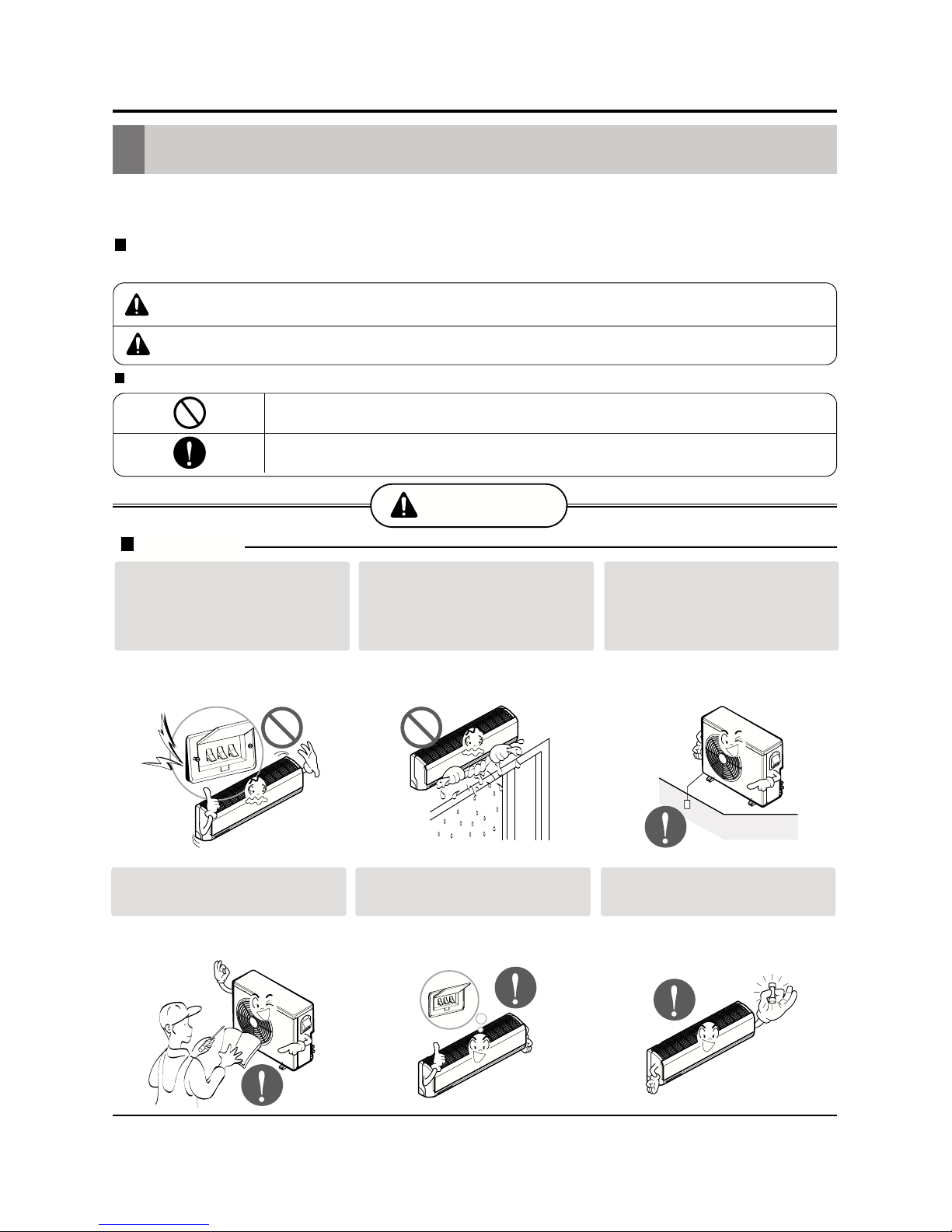
WARNING
Installation
Be sure not to do.
Be sure to follow the instruction.
Do not use a defective or
underrated circuit breaker.
Use this appliance on a dedicated circuit.
• There is risk of fire or electric shock.
Do not let the air conditioner
run for a long time when the
humidity is very high and a
door or a window is left open.
• Moisture may condense and wet or
damage furniture.
Always ground the product.
• There is risk of fire or electric shock.
Install the panel and the cover
of control box securely.
• There is risk of fire or electric shock.
Always install a dedicated circuit and breaker.
• Improper wiring or installation may
cause fire or electric shock
Use the correctly rated breaker or fuse.
• There is risk of fire or electric shock.
Page 4

4 Multi Air Conditioner
Safety Precautions
Operational
Do not modify or extend the
power cable.
• There is risk of fire or electric shock.
Do not install, remove, or reinstall the unit by yourself
(customer).
• There is risk of fire, electric shock,
explosion, or injury.
Be cautious when unpacking
and installing the product.
• Sharp edges could cause injury. Be
especially careful of the case edges
and the fins on the condenser and
evaporator.
For installation, always contact the dealer or an
Authorized Service Center.
• There is risk of fire, electric shock,
explosion, or injury.
Do not install the product on a
defective installation stand.
• It may cause injury, accident, or damage to the product.
Be sure the installation area
does not deteriorate with age.
• If the base collapses, the air conditioner could fall with it, causing property
damage, product failure, and personal
injury.
Do not touch(operate) the
product with wet hands.
• There is risk of fire or electrical shock.
Do not place a heater or other
appliances near the power
cable.
• There is risk of fire and electric shock.
Do not allow water to run into
electric parts.
• It may cause There is risk of fire, failure of the product, or electric shock.
Page 5

Service Manual 5
Safety Precautions
Do not open the inlet grille of the product during operation. (Do not touch the electrostatic
filter, if the unit is so equipped.)
• There is risk of physical injury, electric shock, or product failure.
Be cautious that water could not enter the
product.
• There is risk of fire, electric shock, or product damage.
Do not store or use flammable gas or combustibles near the product.
• There is risk of fire or failure of product.
If strange sounds, or smell or smoke comes
from product. Turn the breaker off or disconnect the power supply cable.
• There is risk of electric shock or fire.
Gasolin
Page 6

6 Multi Air Conditioner
Operational
Safety Precautions
Use two or more people to lift
and transport the product.
• Avoid personal injury.
Use a soft cloth to clean. Do
not use harsh detergents, solvents, etc.
• There is risk of fire, electric shock, or
damage to the plastic parts of the product.
Do not touch the metal parts
of the product when removing
the air filter. They are very
sharp!
• There is risk of personal injury.
Do not step on or put anyting on the product.
(outdoor units)
• There is risk of personal injury and failure of product.
Do not insert hands or other objects through
the air inlet or outlet while the product is operated.
• There are sharp and moving parts that could cause personal
injury.
CAUTION
Installation
Wax
Thinner
check for gas (refrigerant)
leakage after installation or
repair of product.
• Low refrigerant levels may cause failure of product.
Install the drain hose to
ensure that water is drained
away properly.
• A bad connection may cause water
leakage.
Keep level even when
installing the product.
• To avoid vibration or water leakage.
90Û
Page 7
Service Manual 7
Product Specifications
Product Specifications
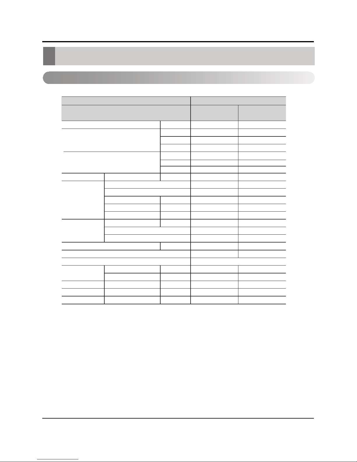
Indoor Unit
Power Supply Ø,V,Hz
rh/utByticapaC gnilooC
yticapaCHeating
W
kcal/hr
rh/utB
W
kcal/hr
Current Normal running current A
Fan Model
Fan Type
Motor Output W
Air Flow Rate CMM(CFM)
Capacitor µF/Vac
Coil Tube Size (OD) mm(inch)
Fins per inch
No. of Rows & Column/No.
3±)A(Bd)L/M/H(leveL dnuoS
Referigerant
Referigerant Control
)hcni(mmdiuqiLnoitcennoC gnipiP
)hcni(mmsaG
)sbl(gkroodnIthgieW teN
)hcni(mmD*H*WsnoisnemiD
)hcni(mmD*H*W noisnemiD gnikcaP
Model
TMNH092DYAA
TMNH122DYAA
detnuom llaWepyt tinu roodnI
1Ø, 220V, 60Hz 1Ø, 220V, 60Hz
0.270.20
CFF
RP15C-1 WEILINGRP15C-1 WEILING
42
8.4/7.6/6.4(296.5/268.3/225.9) 7/6/5(247.1/211.8/176.5)
0.9/400
20FPI S-FIN
2R 15C
R-22R-22
6.35(1/4)
12.7(1/2)
7/9
840*270*161
6.35(1/4)
9.52(3/8)
7/9
840*270*161
892*322*198 892*322*198
5
CFF
37
0.9/400
20FPI S-FIN
2R 15C
34/31/29 40/37/34
Thermistor
5
12,000
3,517
3,024
9,000
2,638
2,268
12,000
3,517
3,024
9,000
2,638
2,268
Page 8
8 Multi Air Conditioner
Product Specifications
Note :
1. Capacities are based on the following conditions:
Cooling: - Indoor Temperature 26.7°C(80°F) DB / 19.4°C(67°F) WB
- Outdoor Temperature 35°C(95°F) DB / 23.9°C(75°F) WB
Piping Length - Interconnecting Piping Length 7.5m
- Level Difference of Zero.
2. Due to our policy of innovation some specifications may be changed without notification.
3. At least two indoor units should be connected.
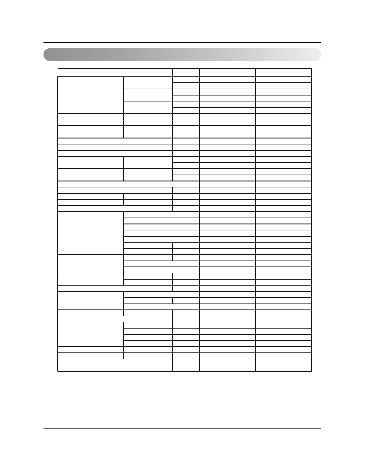
Outdoor Unit
Unit T2UH182FAA T2UH242FAA
W 3077/ 3077 3517 / 3517
Btu/hr 10500 / 10500 12000 / 12000
W 3077/ 3077 3517 / 3517
Btu/hr 10500 / 10500 12000 / 12000
W 5275 / 5275 7034
Btu/hr 18,000 / 18,000 24,000
Power input
(Cooling/heating)
A+B W 1850/1650 2380/2420
Running current
(Cooling/heating)
A+B A 8.6/ 7.6 11/11.3
f,V,Hz 1,220,60 1,220,60
No. * mm
2
3*2.5 3*2.5
No. * mm
2
4*0.75 4*0.75
W/W 2.85 2.96
Btu/hr W 9.7 10.1
W/W 3.20 2.91
Btu/hr W 10.9 9.9
Capillary Capillary
g(oz), type 1050, R22 A: 650 /B: 650 R22
Dimensions (W*H*D)
Outdoor unit mm 801*555*262 870*655*320
Packing dimensions (W*H*D)
Outdoor unit mm 960*610*384 1002*700*422
kg (lbs) 50 (110) 63 (139)
Rotary Rotary
1 2
QJ278KDF QK185KBK
LG LG
SUNISO 4GSI SUNISO 4GSI
MOTOR TYPE PSC PSC
Oil charge cc 410 350
Tube size (OD) inch (mm) 0.276 (7.0) 0.276 (7.0)
18 18
2R 24C 2R 28C
Model YGK25-6A-9 KFD-60K11
No. of poles 6 6
CMM (CFM) 49 (1398) 40 (1142)
Propeller Propeller
No. used / dia.
1 / 18.1(460) 1 / 18.1(460)
Side discharge Side discharge
RPM ±30 1020 880
dB +3(dB+1) 54(56) 54(56)
Liquid A inch (mm) 1/4 (6.35) 1/4 (6.35)
Gas A inch (mm) 3/8 (9.52) 1/2 (12.7)
Liquid B inch (mm) 1/4 (6.35) 1/4 (6.35)
Gas B inch (mm) 3/8 (9.52) 1/2 (12.7)
Max piping length total
m 30 30
Std. Piping length m 7.5 7.5
m 15 / 7.5 15 / 7.5
Stuff Quantity (Set) 20FT/40FT/40FT(H) 80/168/192 65/138/156
Power supply
Power supply cable
Connecting cable
Item
Capacity
(Cooling/heating)
A (SY 9K)
B (SY 9K )
A+B (9K+9K)
EER
cooling
COP
heating
Refrigerant control
Refrigerant charge
Net weight
Compressor
Type
Quantity
Model name
Maker
Oil type
Outdoor coil
FPI
No. of rows & columns
Noise level +3
SVC valves
Max. piping length per each room / elevation
Outdoor Motor
Air circulation
Outdoor fan
Type
Dischage
Page 9

Service Manual 9
Dimensions
Dimensions
Installation plate
D
H
W
mmW
mmH
mmD
Model
Dimension
Indoor Unit
TMN 122DYAATMNH092DYAA
840
270
161
840
270
161
H
Page 10
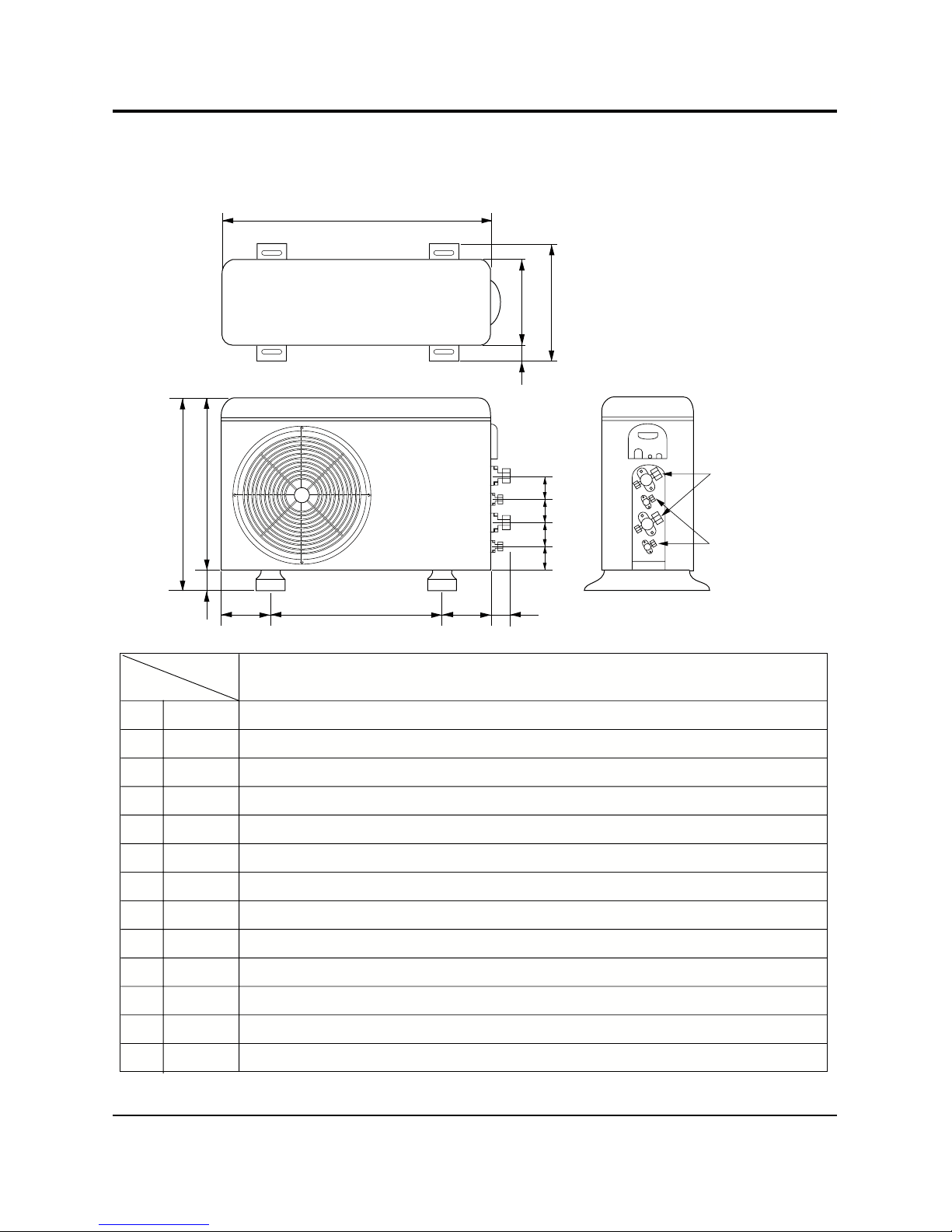
10 Multi Air Conditioner
Dimensions
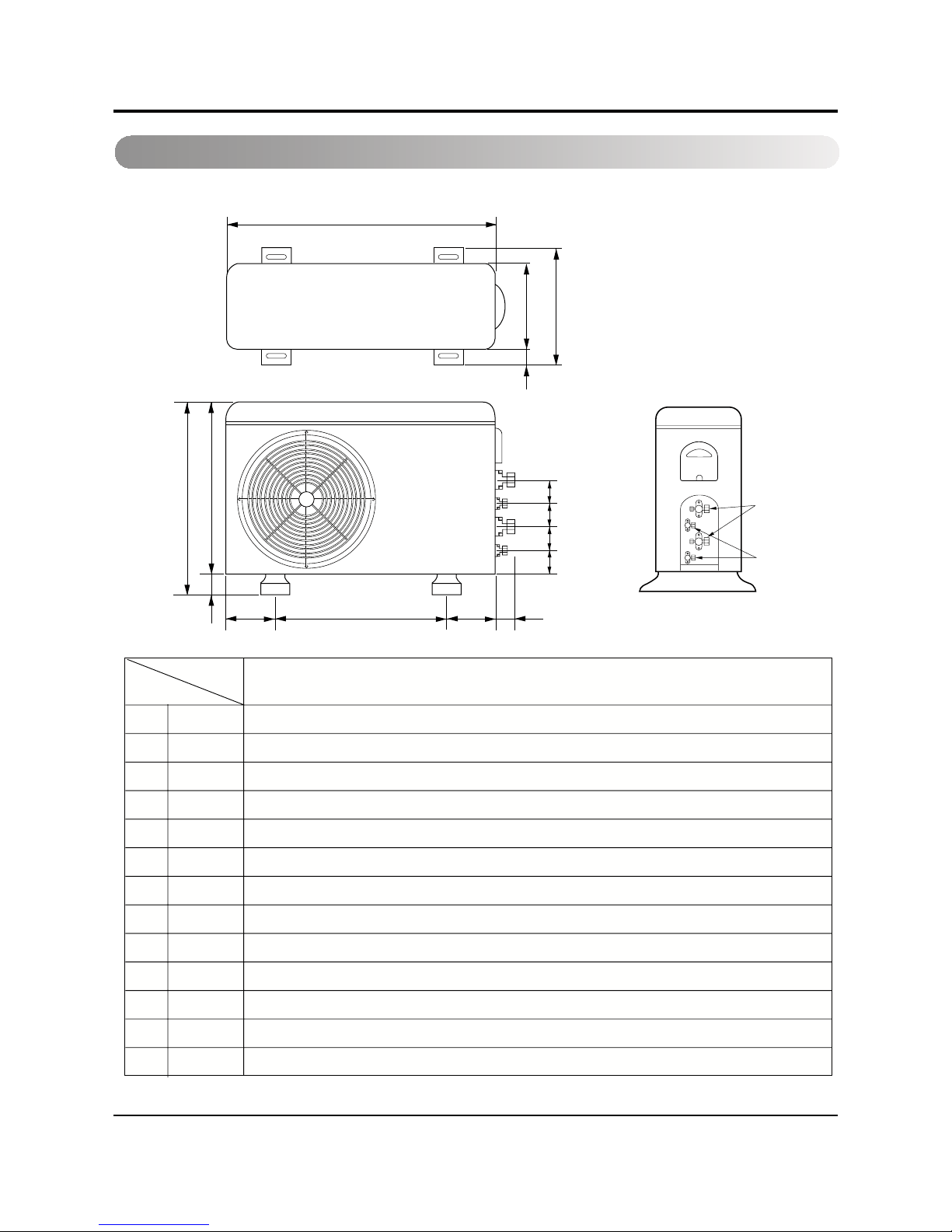
Outdoor Unit
Model: T2UH182FAA
W
D
L1
L2
L9
L4
L3
H
L10
L10
L10
L8
L7L5L6
801mmW
555mmH
262mmD
339mm1L
37mm2L
543.6mm3L
11.4mm4L
591mm5L
105mm6L
105mm7L
72.5mm8L
74.5mm9L
79mm01L
T2UH182FAA
MODEL
DIM
Gas side
3-way valve
Liquid side
2-way valve
Page 11
Service Manual 11
Dimensions
Model : T2UH242FAA
W
D
L1
L2
L9
L4
L3
H
L10
L10
L10
L8
Gas side
3-Way valve
Liquid side
2-Way valve
L7L5L6
870mmW
655mmH
023mmD
073mm1L
52mm2L
630mm3L
52mm4L
645mm5L
061mm6L
061mm7L
55mm8L
80mm9L
05mm01L
T2UH242FAA
MODEL
DIM
Page 12
12 Multi Air Conditioner
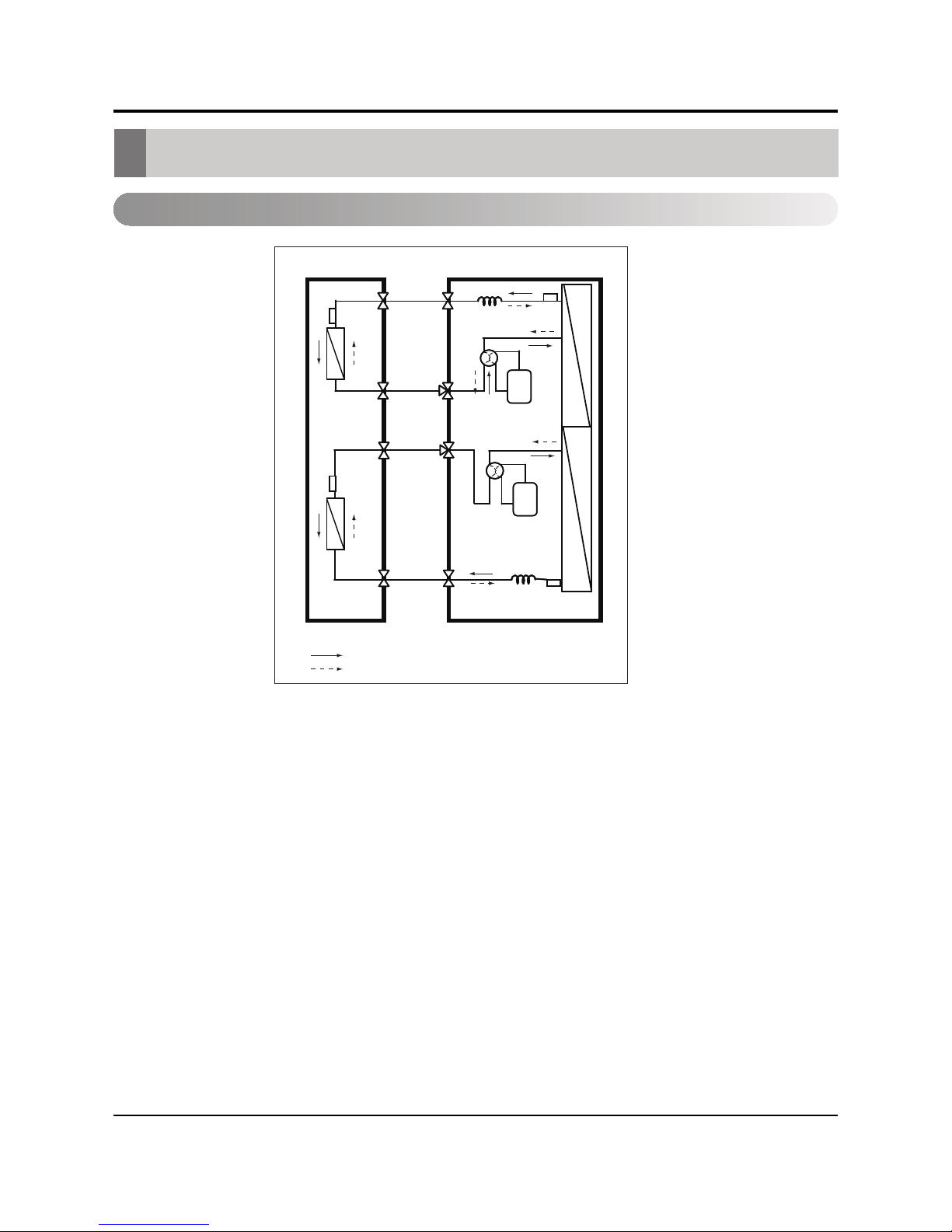
Refrigeration Cycle Diagram
Refrigeration Cycle Diagram
T2UH182FAA / T2UH242FAA
12K
12K
A
B
Indoor Side
Outdoor Side
A
Comp
B
Comp
Refrigerent Flow
Cooling
Heating
Page 13

13Service Manual
Wiring Diagram
Wiring Diagram
Indoor Unit
Outdoor Unit
T2UH242FAA.2T2UH182FAA.1
FAN
B/P1
B/P2
BC
EBY49965301
RD BRYL
2
BKWH
1
BLRD
BL
RD
WH BL
BK
BL
OR
BL
BL
BL
WH
TB
BC
BL
BR
BR
BR
BR
BK
EBY49965302
3
4
TB
LN
Page 14

14 Multi Air Conditioner
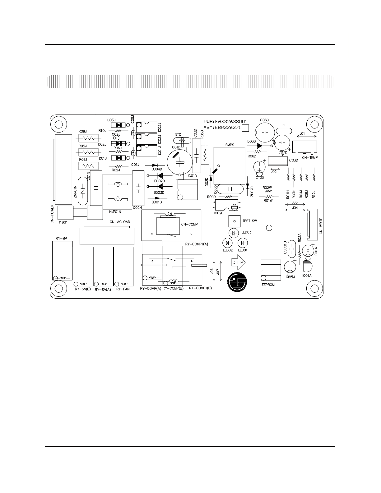
Electronic Control Device
Electronic Control Device
Indoor Unit
• MAIN P.C.B ASM
• TOP VIEW
• BOTTOM VIEW
Page 15
Service Manual
Electronic Control Device
Outdoor Unit
15
Page 16

Multi Air Conditioner
Electronic Control Device
Display P.C.B ASM
16
Page 17

Service Manual
Schematic Diagram
Schematic Diagram
Indoor Unit
42
28
15
16
22
20
19
18
17
21
26
25
23
24
27
11
12
13
14
9
8
10
34
33
32
29
30
31
38
37
36
35
41
40
39
53
55
56
58
57
54
61
63
62
64
60
59
5
4
7
6
1
3
2
49
51
52
50
44
45
43
48
46
47
FAN
12V
4WAY
COMP
OUTDOOR FAN
L(AC)
COMP
4WAY
LOAD
2. The unit of undefined capacitors is uF.
1. The unit of undefined resistance is ohm, 1/8W, 5%.
NOTE
Direct type
123
PCB outside
12
Angle type
CN-MOTOR
321
CN-4WAY
SH-CAPACITOR
22
680
33
CN-12V
2
1
1
2
2
1
12V
AC PART
3
TLP421(V4 BL)
IC01L
VOLTAGE GND
DC LOW
INT
4
1N4148
VOLTAGE GND
2
DC HIGH
300K
1/2W
NF01J
40mH/1A
1IN4007
1N4007
D05J
R03L
300K
1/2W
27k
1/6W
D01L
1
R02L
R01L
1N4007
5V
1N4007
D03J
C02J
100nF/275V/436D
METAL FILM
D02J
1N4007
D01J
D04J
12V
INDOOR FAN
R01F
560
1/4W
100,1/2W
250V/T2A
100nF/275V/436D
C01J
METAL FILM
ZNR01J
TVR10561
FUSE
RY- FAN
RY-4 WAY
3
434
TLP762JF
SM1L43
T1
R03F
1/2W
5
1
2
4
IC01F
3
TR01F
TRAICS
T2
METAL FILM
100nF/275V/436D
C01F
TVR10561
120, 1/2W
R04F
ZNR01F
COMPRESSOR
11
CN-N1
RY-COMP
G4A-1A-E-LG
3
N
50/60Hz
AC220~240V
L
MOTOR
4
11
33
11
22
3
1
2
3
1
2(N)
1(L)
2
TERMINAL
5
4
5
FAN MOTOR
OUTDOOR
4-WAY
4
11
2
4
3
5
Vout
GND
Vcc
RECEIVER
DISPLAY
C
CAB
B
KTC3198-Y
1
1
11
20K
(2012)
R01P
10V
2
2
HVB
33
1
CN-HVB
1
Option
HVB OUT
6
3
A0
A1
M24C01-MN6T SGS-THOMSON 8PIN SOP TRAY EEPROM IIC
EEPROM
4
SCL
SDA
5
G
A2
1
2
8
Vcc
7
WP
receiver
5555
C13L
SW(FORCE)
104
2 2
11
22
11
44
3
3
44
3
3
R01G~R04G1220 1/8W
7
7
6 6
77
66
8 8 88
CN-DISP1
KRA107S
Q02G
KRA107S
Q03G
220uF SD
Force
+
C12L
5V
Q01G
KRA107S
5V
KID65004AF
9
IC01G
5V
5V
20K
R02P
(2012)
OR4HOR6HOR5H
Hi Med Low
OR3H OR1HOR2H
O/L F2 F1
R26H
R21H
5V
d
5V
s1s
V
d
Force
20K
R15L
5V
C08D,AXIAL
103,50V
A
V
A
Vss0
Vdd0
AVref
R24H
R23H
R25H
12.1K, 1%
R21H~R26H
R22H
5V
RESET
AVdd
C07D,AXIAL
103,50V
X2
X1
CRTL8.00MSOT
CSTS0800MG03-T2
R01B
1M
OSC01B
2SC5343
R03G
OUTDOOR
OPERATION
LED2
SLEEP
LED1
A
TIMER
LED3
R02G
R01G
3
3
2 2
3
3
2
2
6644
55
6
6
5
5
4
4
LED4
R04G
77
7
7
11 6
16
15
14
1
2
3
13
12
4
5
12V
10 7
KID65004AF
IC01M
BL
OR
4
5
RD
4
5
2
1
3
PK
YL
2
1
3
STEPPING MOTOR
(UP/DOWN)
HVB OUT
15 2
8
16
9
1
13
14
3
4
INDOOR FAN
COMP
10
11
12
5
6
7
UPD780023AGC-C
NEC
INT1
Vss1
INT0
B
Z
Q01L
R11L,1/6W
FAN
12
4
1
2
3
16 15 14 13
2
4
3
5
4WAY
KID65004AF
8
7
5
6
91011
IC02M
1
CN-L/R
DC PART
STEPPING MOTOR
(LEFT/RIGHT)
Option
1
INT
RELAY CONNECTION
CN-TH1
10K
R05H
R02H
12.1K
1%
R04H
6.2K
1%
5V
PIPE-TH
R02F
114422
33
ROOM-TH
50V
5V
3
10uF
C02A
IC01A
1
3.6V
S71362KIA7036P
R05L
56K
R02A,4.7K
CN-MOTOR
33
FAN
INDOOR
MOTOR
3
4
R12L 5.1K
receiver
680pF,50V
12K
R04L,1/6W
5V
C11L ,AXIAL
5V
PKM13EPY-4002
R02E,20
R01E
1K
BZ01E
IC01J
DMR40 EE1916S
Lp=4.50mH,+-8%,40Khz
158T
VOLTAGE GND
DC LOW
+
5V
C04D
C05D
10V SD
104,AXAIL
50V
220
S78L05L 1WIIC01D
O
7805
D01D
UF4004
ZBF503D-TA-K TDK TP 12uH
L01D,IMD
1/6W
104,AXIAL
C03D
R01D
4.7K
50V
100uF
C02D
25V
12V
28T
220UF
C01D
25V
SMPS
450V/SD
1N4937
DC HIGH
VOLTAGE GND
100,1/6W
R02J
50V
C05J
0.1uF
100V
RO1J
1/4W,1%
27K
DO6J
1uF
C04J
LNK500P
S
D
C
+
10uF
C03J
NTC SCK-102
CI-B2012-100KJT R/TP 100nH
L02D
2
5
4
5
4
3
1
3
1
2
12V
5V
GND
R14L
1K
C01P,AXIAL,103,50V
X
RT
X
DD
R01A,1K
R03A,100
AXIAL
C01A
103
222,400V
C06J,AXIAL
+
1
2
1
2
33
12V
CN-P/O
+
R01H,1/6W,10K
R03H,1/6W,10K
C14L
C02H
C01H
R13L
100 1/4W
12V
BLPKYLORRD
8
PLASMA
CHIP
RXD
TXD
C03T
CHIP
R06H,1/6W,10K
C03H
231
231
CN-TH2
6.2K
R07H
1%
5V
113322
77
66
55
44
CN-OPTION
GND
OR1H (PIN 33)
OR2H (PIN 32)
OR3H (PIN 31)
OR4H (PIN 30)
OR5H (PIN 29)
OR6H (PIN 28)
C01L
AXIAL
33
CN-RF
5V
1122
CHIP(104) or 10K ohm resistor
C01T
R01T,1K,AXIAL
CHIP(681)
C02T
1
38
6
Metal film
+
LINK SWICH
CN-4WAY
CN-N2
CN-LIVE
WIRE-N
R02D
C06D,AXIAL
4.7K,1/6W
102,400V
WIRE-N
3
4
CN-LIVE
PTC-HEATER
RF
Transmitter
on artworking,Eyelet pattern
10M,1W,5% noise character increasing thing
R03J
103
103
103
YW396-03AV(WH)
YW396-03AV(YL)
103
1K
102 or 10K ohm resistor
AXIAL AXIAL
50V 50V
AXIAL
50V
50V
103
50V
CN-DISP2
CN-U/D
CN-CENT
SMD
BARE PCB:6870A90238A
ASM PCB:6871A20572
DISPLAY BARE PCB : 6870A90240A
DISPLAY ASM PCB : 6871A20574A
If CN-CENT don't use,this use resistor 10K(2012).
OR1H
OR2H
OR3H
OR4H
OR5H
OR6H
PCB ASM : 6871A20577
If CN-RF don't use,this use resistor 10K(2012).
2UEW0.14 TIW0.25
Option : only This is applied the H/P SRAC.
P/no:6200JB8010P WRAC APPLIED
OPTION : noise character increasing thing
OPTION : noise character increasing thing
PWB:6870A90243A
10K
47K
47K
10K
47K
10K
Only no low temporature detection function.
10K+-5%
5K+-5%
15pF
15pF
GLASS TYPE
R11H
R12H
5V
0J1H0J2H
5V
OPTION : import or export operation option
R11H~R12H
20K,2012
1-4 79T
4-3 79T
R04D
0 ohm
0 ohm
R03D
C09D
open
C10D
open
Anti Surge Res.
Anti Surge Res.
Anti Surge Res.
17
Page 18

Schematic Diagram
18 Multi Air Conditioner
Page 19

Service Manual
Functions
Function of Indoor Unit
• Room temperature sensor. (THERMISTOR)
• Maintains the room temperature in accordance with the Setting Temp.
• Indoor fan is delayed for 5 seconds at the starting.
• Restarting is inhibited for approx. 3 minutes.
• High, Med, Low, Chaos
--- Lights up in operation
--- Lights up in Sleep Mode
--- Lights up in Energy Saving Mode
--- Lights up in Defrost Mode(for Heating model)
--- Lights up in Compressor operation(for Cooling model)
• Intermittent operation of fan at low speed.
• The fan is switched to low(Cooling), med(Heating) speed.
• The unit will be stopped after 1, 2, 3, 4, 5, 6, 7 hours.
• The fan is switched to intermittent or irregular operation
•
The fan speed is automatically switched from high to low speed.
• The louver can be set at the desired position or swing
up and down automatically.
Wall mounted type
Operation ON/OFF by Remote controller
Sensing the Room Temperature
Room temperature control
Starting Current Control
Time Delay Safety Control
Indoor Fan Speed Control
Operation indication Lamps (LED)
OUT
DOOR
Health Dehumidification Operation
Sleep Mode Auto Control
Natural Air Control by CHAOS Logic
Airflow Direction Control
19
Page 20

Multi Air Conditioner
Functions
Healthy Dehumidification Operation Mode.
( )
Remote Controller
Operation ON/OFF
Operation Mode Selection
Temperature Setting
JET COOL
Sleep Operation
Airflow Direction Control
(Cooling
model only)
TEMPERATURE
LOW HIGH
Cooling Operation Mode.( )
Heating Operation Mode.( )
Fan Operation Mode
Energy Saving Mode
Fan Speed Selection
(Low) (Med) (High) (CHAOS)
: Cancel Sleep Mode, Timer ON or Timer OFF
: 1, 2, 3, 4, 5, 6, 7, Off Timer
: Fan Operates without cooling or heating.
Cooling
Down to 18°C
Up to 30°C
20
Page 21

Service Manual 2
Function
Display Function
Self-diagnosis Function
• Cooling, Soft Dry, Fan
• Sleep Mode
Operation Indicator
Energy Saving Mode
Sleep Timer Indicator
Compressor on Indicator
OUT
DOOR
Error Indicator
• The function is to self-diagnoisis airconditioner and express the troubles identifically if there is any trouble.
• Error mark is ON/OFF for the operation LED of evaporator body in the same manner as the following table.
• If more than two troubles occur simultaneously, primarily the highest trouble fo error code is expressed.
• After error occurrence, if error is released, error LED is also released simultaneously.
• To operate again on the occurrence of error code 12, be sure to pull out power cord and then re-insert.
• Having or not of error code is different from Model.
ledoM gnilooC
3sec 3sec 3sec
(once)
Error
Code
1
Error Display LED
(Indoor body operation LED)
Error contents
• Indoor room temperature
thermistor open/short
• Indoor pipe temperature
thermistor open/short.
• Indoor Thermistor
assembly check
SVC check point
1
Page 22

2 Multi Air Conditioner
Operation Details
Operation Details
Function of Controls
• DISPLAY
C/O Model
Operation Indicator
• ON while in appliance operation, OFF while in appliance pause.
•
Sleep Mode
Comp. Running Incidator
•
Cooling Mode Operation
• Whenthe intake air temperature reaches0.5 °C below the setting temp, the compressorand the outdoor fan
stop.
• When itreaches0.5 °C above the setting temp, they start to operate again.
Compressor ON Temp
Setting Temp+0.5°C
Compressor OFF Temp
Setting Temp-0.5°C
• Whilein compressorrunning, operating with the
speedset by the remote control. While in compressor
Health
•Whenthe operation input by the remote control is received,the intake air temperature is
detected and the setting temp is automatically set according to the intake air temperature.
26°C Intake Air Temp
25°C
24°C Intake Air Temp<26°C
Intake Air Temp-1°C
18°C Intake Air Temp<24°C
Intake Air Temp-0.5°C
Intake Air Temp<18°C
18°C
•
• Whilethe intakeair temp isbetween compressoron temp. and compressor temp.,10-min
Compressor ON Temp. Setting Temp+0.5°C
Compressor OFF Temp.
Setting Temp-0.5°C
•
Energy Saving Mode
2
Page 23

Operation Details
Airflow Speed Selection
• The airflow speed of the indoor fan is set to high, medium, low, or chaos (auto) by the input of the airflow
speed selection key on the remote control.
Sleep Timer Operation
• When the sleep time is reached after <1,2,3,4,5,6,7,0(cancel) hr> is input by the remote control while in appliance operation, the operation of the appliance stops.
• While the appliance is on pause, the sleep timer mode cannot be input.
• While in cooling mode operation, 30 min later since the start of the sleep timer, the setting temperature
increases by 1°C. After another 30 min elapse, it increases by 1°C again.
• When the sleep timer mode is input while in cooling cycle mode, the airflow speed of the indoor fan is set to
the low.
• When the sleep timer mode is input while in heating cycle mode, the airflow speed of the indoor fan is set to
the medium.
Chaos Natural Wind Mode
• When the Chaos Natural Wind mode is selected and then operated, the high, medium, or low speed of the airflow mode is operated for 2~15 sec. randomly by the Chaos Simulation.
Jet Cool Mode Operation (C/O Model)
• If the Jet Cool key is input at any operation mode while in appliance operation, the Jet Cool mode operates.
• In the Jet Cool mode, the indoor fan is operated at super-high speed for 30 min at cooling mode operation.
• In the Jet Cool mode operation, the room temperature is controlled to the setting temperature, 18°C
• When the sleep timer mode is input while in the Jet Cool mode operation, the Jet Cool mode has the priority.
• When the Jet Cool key is input, the upper/lower vanes are reset to those of the initial cooling mode and then
operated in order that the air outflow could reach further.
Forced Operation
• Operation procedures when the remote control can't be used.
• The operation will be started if the power button is pressed.
• If you want to stop operation, re-press the button.
• While in forced operation, the key input by the remote control has no effect and the buzzer sounds 10 times to
indicate the forced operation.
Heat pump Model
Cooling Model
Room Temp. 24°C 21°C Room Temp. < 24 °C Room Temp. < 21 °C
Operating mode Cooling Cooling Healthy Dehumidification Heating
Indoor FAN Speed
High High High High
Setting Temperature
22°C 22°C 23°C 24°C
Test operation
•
During the TEST OPERATION, the unit operates in cooling mode at high speed fan, regardless of room temperature and resets in 18±1 minutes.
•
During test operation, if remote controller signal is received, the unit operates as remote controller sets.
If you want to use this operation, open the front panel upward and Press the power button let it be pressed for
about 3 seconds.
•
If you want to stop the operation, re-press the button.
Service Manual 23
Page 24

Operation Details
Auto restart
•
In case the power comes on again after a power failure, Auto Restarting Operation is the function to operate
procedures automatically to the previous operating conditions.
Protection of the evaporator pipe from frosting
• If the indoor pipe temp is below 0°C in 7 min. after the compressor operates without any pause while in cooling cycle operation mode, the compressor and the outdoor fan are turned off in order to protect the indoor
evaporator pipe from frosting.
• When the indoor pipe temp is 7°C or higher after 3 min. pause of the compressor, the compressor and the
outdoor fan is turned on according to the condition of the room temperature.
Buzzer Sounding Operation
• When the appliance-operation key is input by the remote control, the short "beep-beep-" sounds.
• When the appliance-pause key is input by the remote control, the long "beep—" sounds.
24
Multi Air Conditioner
Page 25

25Service Manual
Operation Details
Remote Control Operations
Page 26

Disassembly
Disassembly
Indoor Unit
Disconnect the unit from power supply before making any checks.
Be sure the power switch is set to “OFF ”.
To remove the Grille from the Chassis.
• Set the up-and-down air discharge louver to open
position (horizontally) by nger pressure.
• Remove the securing screws.
• To remove the Grille, pull the lower left and right
side of the grille toward you (slightly tilted) and lift it
straight upward.
1. Before removing the control box, be sure to
take out the wire screwed at the other end.
Earth
Conductor
26 Multi Air Conditioner
Page 27

Disassembly
2. To remove the Control Box.
• Remove securing screws.
• Pull the control box out from the chassis
carefully.
3. To remove the Discharge Grille.
• Unhook the discharge grille and pull the
discharge grille out from the chassis carefully.
4. To remove the Evaporator.
• Remove 3 screws securing the evaporator(at the
left 2EA in the Eva Holder, at the right 1EA).
Screw
• When repair, do not damage the Caution label.
Service Manual 27
Page 28

Disassembly
• Unhook the tab on the right inside of the chassis
at the same time, slightly pull the evaporator
toward you until the tab is clear of the slot.
5. To remove the Motor Cover
• Remove 2 securing screw.
• Pull the motor cover out from the chassis
carefully.
6. To remove the Cross-Flow Fan
• Loosen the screw securing the cross-flow fan to
the fan motor (do not remove).
• Lift up the right side of the cross-flow fan and the
fan motor, separate the fan motor from the
cross-flow fan.
• Remove the left end of the cross-flow fan from
the self-aligning bearing.
Motor cover
Bearing
Cross-flow fan
28 Multi Air Conditioner
Page 29

2-way, 3-way Valve
2-way, 3-way Valve
2-way Valve (Liguid Side) 3-way Valve (Gas Side)
Works Shaft position Shaft position Service port
Shipping Closed Closed Closed
(with valve cap) (with valve cap) (with cap)
Air purging Open Closed Open
(Installation) (counter-clockwise) (clockwise) (push-pin or with
vacuum pump)
Operation Open Open Closed
(with valve cap) (with valve cap) (with cap)
Pumping down Closed Open Open
(Transfering) (clockwise) (counter-clockwise) (connected
manifold gauge)
Evacuation Open Open Open
(Servicing) (with charging
cylinder)
Gas charging Open Open Open
(Servicing) (with charging
cylinder)
Pressure check Open Open Open
(Servicing) (with charging
cylinder)
Gas releasing Open Open Open
(Servicing) (with charging
cylinder)
3.
2.
1.
4.
5.
6.
Flare nut
To
piping
connection
Open position
Closed position
Flare nut
Valve cap
To
piping
connection
Open position
Closed position
Hexagonal wrench
(4mm)
To outdoor unit
Pin
Service
port
Service
port cap
To outdoor unit
Service Manual 29
Page 30

2-way, 3-way Valve
•
Procedure
1. Confirm that both the gas side and liquid side
valves are set to the open position.
- Remove the valve stem caps and confirm that
the valve stems are in the raised position.
- Be sure to use a hexagonal wrench to operate
the valve stems.
2. Operate the unit for 10 to 15 minutes.
3. Stop operation and wait for 3 minutes, then connect the manifold gauge to the service port of
the gas side valve.
- Connect the hose of the gauge with the push
pin to the service port.
4. Air purging of the charge hose.
- Open the Low-handle valve on the gauge
slightly to air purge from the hose.
5. Set the liquid side valve to the closed position.
6. Operate the air conditioner at the cooling cycle
and stop it when the gauge indicates 1kg/cm
2
g.
7. Immediately set the gas side valve to the closed
position.
- Do this quickly so that the gauge ends up indi-
cating 1kg/
g.
8. Disconnect the charge set, and mount the liquid
side and gas side valve caps and the service
port nut.
- Use torque wrench to tighten the service port
nut to a torque of 1.8kg.m.(4.2kg*m/5.5kg*m)
- Be sure to check for gas leakage.
Indoor unit
Outdoor unit
Liquid side
Close
Gas side
2-Way
valve
Open
3-Way
valve
manifold gauge
Hi- handle
(CLOSE)
Low-handle
(CLOSE)
(1) Pumping down
30 Multi Air Conditioner
Page 31

2-way, 3-way Valve
(2) Evacuation
(All amount of refrigerant leaked)
• Procedure
1. Confirm that both the liguid side valve and gas
side valve are set to the opened position.
2. Connect the vaccum pump to the center hose of
the manifold gauge.
3. Connect the service port of the gas side valve to
the low side of the gauge.
4. Connect power supply to outdoor unit.
5. Evacuation for approximately one hour.
- Confirm that the gauge needle has moved
toward-76 cmHg (vacuum of 4 mmHg or less).
6. Close the Low handle of the gauge turn off the
vacuum pump, and confirm that the gauge needle does not move(approximately 5 minutes
after turning off the vacuum pump).
7. Disconnect the charge hose from the vacuum
pump.
- Vacuum pump oil.
If the vacuum pump oil becomes dirty or depleted,replenish as needed.
8. Mount the valve caps and the service port caps.
Indoor unit
Outdoor unit
Liquid side
Close
Gas side
2-Way
valve
Open
3-Way
valve
manifold gauge
Vacuum pump
Hi- handle
(CLOSE)
Lowhandle
(OPEN)
Service Manual 31
Page 32

2-way, 3-way Valve
(3) Gas Charging
(After Evacuation)
• Procedure
1. Connect the gauge to the charging cylinder.
- Connect the charge hose which you disconnected from the vacuum pump to the valve at the
bottom of the cylinder.
- If you are using a gas cylinder, also use a scale
and reverse the cylinder so that the system can
be charged with liquid.
2. Purge the air from the charge hose.
-
Open the valve at the bottom of the cylinder and
press the check valve on the charge set to purge
the air. (Be careful of the liquid refrigerant). The
procedure is the same if using a gas cylinder.
3. Open the low handle on the gauge and charge
the system with liquid refrigerant.
- If the system can not be charged with the specified amount of refrigerant, it can be charged
with a little at a time (approximately 150g each
time) while operating the air conditioner in the
cooling cycle; however, one time is not sufficient, wait approximately 1 minute and then
repeat the procedure(pumping down-pin).
4. Immediately disconnect the charge hose from
the gas side valve's service port.
- Stopping partway will allow the gas to be dis-
charged.
- If the system has been charged with liquid
refrigerant while operating the air conditioner
turn off the air conditioner before disconnecting
the hose.
5. Mount the valve stem nuts and the service port
nut.
- Use torque wrench to tighten the service port
nut to a torque of 1.8 kg.m.(4.2kg.m/5.5kg.m.)
- Be sure to check for gas leakage.
Indoor unit
Outdoor unit
Liquid side
Close
Gas side
2-Way
valve
Open
3-Way
valve
manifold gauge
Charging
cylinder
Hi- handle
(CLOSE)
Low-handle
(OPEN)
Check valve
This is different from previous procedures.
Because you are charging with liquid refrigerant
from the gas side, absolutely do not attempt to
charge with larger amounts of liquid refrigerant
while operating the air conditioner.
32 Multi Air Conditioner
Page 33

Cycle Troubleshooting Guide
Cycle Troubleshooting Guide
Trouble analysis
1. Check temperature difference between intake and discharge air and operating current.
All amount of refrigerant leaked out.
Check refrigeration cycle.
Refrigerant leakage
Clog of refrigeration cycle
Defective compressor
Excessive amount of refrigerant
Normal
Notice:
Temperature difference between intake and discharge air depends on room air humidity. When the room air
humidity is relativery higher, temperature difference is smaller. When the room air humidity is relatively lower
temperature difference is larger.
2. Check temperature and pressure of refrigeration cycle.
Notice:
1. The suction pressure is usually 4.5~6.0 kg/cm
2
G at normal condition.
2. The temperature can be measured by attaching the thermometer to the low pressure tubing and wrap it with
putty.
Temp. difference : approx. 0°C
Current : less than 80% of
rated current
Temp. difference : approx. 8°C
Current : less than 80% of
rated current
Temp. difference : less than 8°C
Current : over the rated
current
Temp. difference : over 8°C
Temp. Difference
Operating Current
Suction pressure Temperature
(Compared with (Compared with Cause of Trouble Description
the normal value) the normal value)
High Defective compressor Current is low.
Normal Excessive amount of High pressure does not quickly
refrigerant rise at the beginning of operation.
Insufficient amount of Current is low.
Lower Higher refrigerant(Leakage)
Clogging Current is low.
Higher
Service Manual 33
Page 34

Cycle Troubleshooting Guide
Electronic Parts
Product does not operate at all.
(* Refer to Electronic Control Device drawing and Schematic diagram.)
Turn off Main Power
Turn on Main Power
Does "beeping" sound is made from the Indoor Unit?
Primarily, the operating condition of Micom is OK.
Check the voltage of power (About AC 220V, 60Hz)
• Main power's voltage
• Voltage applied to the unit
• Connecting method of Indoor/Outdoor connecting
cable
• Check PWB Assembly
- Fuse
- Pattern damage
- Varistor(ZNR01J)
Check the connection housing for contacting
• Connector related to CN-NI, RY-COMP NO.3
• Connector related to CN-MOTOR
• Connector contacting of Outdoor Fan/Compressor
• Display PCB Assembly Check
Check each load(Indoor/Outdoor Fan Motor,
Compressor, Stepping Motor) and contacting
condition of related connector
Main PCB Board Operation Check
Items
• SMPS Transformer
(Indoor unit)
- Input Voltage
- Output Voltage(C03D)
• IC01D(7805) Output
(Indoor/Outdoor unit)
• IC01A(KIA7036, Reset IC)
OSC01B(8MHz)
• Replace Trans
• Replace IC01D
• Replace faulty parts
- About AC220V/240V±10% - Check the power voltage
- About DC12V
• DC +5V
• Voltage of IC No.1,
(DC +4.5V over) and Soldering condition.
Content Remedy
NO
YES
(After 10 seconds)
34
Multi Air Conditioner
Page 35

Cycle Troubleshooting Guide
The product is not operate with the remote controller.
Turn on Main Power
While the compressor has been stopped, the compressor does not
operate owing to the delaying function for 3 minutes after stopped.
Caused by other parts except the remote control
Cause by the remote control
When the mark( ) is displayed in LCD screen, replace
battery.
Check the contact of CN-DISP1 connector.
When the compressor stopped Indoor Fan is driven by a low speed.
At this point the wind speed is not controlled by the remote controller.
(When operated in the Sleeping Mode, the wind speed is set to the
low speed by force.)
Check Display PCB Assembly
- Voltage between CN DISP1
- : DC +5V
Check the connecting circuit between the remote controller
MICOM (No.
) - R16(1.5k) - IR LED - TR - R17(1Ω).
or
MICOM (No. ) - R1(1.5k) - IR LED - TR - R2(1Ω).
Check point
• Check the connecting circuit between CN-DIS1
-
R11L(100Ω) - C01A(100nF) - MICOM PIN
• Check Receiver Assembly
61
Service Manual 35
Page 36

Cycle Troubleshooting Guide
Compressor/Outdoor Fan are unable to drive.
Turn on Main Power
Operate "Cooling Mode( )" by setting the desired temperature of the
remote controller is less than one of the indoor temperature by 1°C at least.
When in Air Circulation Mode, Compressor/Outdoor Fan is stopped.
Check the sensor for indoor temperature is attached as close as to be
effected by the temperature of Heat Exchanger(EVA).
When the sensor circuit for indoor temperature and connector are in bad
connection or are not engaged, Compressor/Outdoor Fan is stopped.
• Check the related circuit of RY-FAN.
• Check the indoor temperature sensor is disconnected or not(About 10kΩ / at 25°C).
Turn off Main Power
• Check the electrical wiring diagram of outdoor side.
• Check the abnormal condition for the component of
Compressor/Outdoor Fan Motor.
• Check the "open" or "short" of conmecting wires between indoor and
outdoor.
Check Relay(RY - COMP) for driving compressor.
• When the power(About AC220V/240V) is applied to the connecting wire
terminal support transferred to compressor, PWB Assembly is normal.
• Check the circuit related to the relay.
Check point COMP ON COMP OFF
Between Micom(No.
DC5V DC0V
59) and GND
Between IC01M(No. 15) Below DC 1V
About DC12V
and GND (app)
36 Multi Air Conditioner
Page 37

Cycle Troubleshooting Guide
Check the TRIAC high speed operation by remote control.
(The Indoor Fan Motor is connected)
Turn off Main power
Check the connection of CN-MOTOR
Check the Fan Motor
Check the Fuse(AC250V/T2A)
Turn ON Main Power
Check the related circuit of indoor Fan Motor.
• The pin NO 58 of Micom, and the part for driving TRIAC(the input and
output signal of IC01M, PIN NO 1, 16)
• Check the pattern
• Check the TRIAC
- TRIAC Open: Indoor Fan Motor never operate
- TRIAC short: Indoor Fan Motor always operates in case of ON or OFF.
When indoor Fan does not operate.
The voltage of PIN NO 1(orange) and 3(yellow) of CN-MOTOR.
About AC 180V over About AC 50V over
TRIAC is not damaged TRIAC Check
Service Manual 37
Page 38

Cycle Troubleshooting Guide
• Confirm that the Vertical Louver is normally geared with the shaft of
Stepping Motor.
• If the regular torque is detected when rotating the Vertical Louver with
hands
Normal
• Check the connecting condition of CN-U/D Connector
• Check the soldering condition(on PWB) of CN-U/D Connector
If there are no problems after above checks
• Confirm the assembly conditions that are catching and interfering parts
in the rotation radial of the Vertical Louver
When Vertical Louver does not operate.
Check the operating circuit of the Vertical Louver
• Confirm that there is DC +12V between pin
(RED) of CN-U/D and
GND.
• Confirm that there is a soldering short at following terminals.
- Between , , and of MICOM
- Between , , and of IC01M
- Between
, , and of IC01M
60 61 62 63
38 Multi Air Conditioner
Page 39

Installation
Installation
Select the best Location
1. If an awning is built over the unit to prevent
direct sunlight or rain exposure, make sure
that heat radiation from the condenser is not
restricted.
2. Ensure that the spaces indicated by arrows
around front, back and side of the unit.
3. Do not place animals and plants in the path
of the warm air.
4. Take the air conditioner weight into account
and select a place where noise and vibration
are minimum.
5. Select a place so that the warm air and noise
from the air conditioner do not disturb
neighbors.
Rooftop Installations:
If the outdoor unit is installed on a roof
structure, be sure to level the unit. Ensure the
roof structure and anchoring method are
adequate for the unit location. Consult local
codes regarding rooftop mounting.
more than
20cm
more than
70cm
more than
20cm
Service Manual 39
Page 40

Multi Air Conditioner
Installation
40
Page 41

Service Manual
Installation
Piping Length and Elevation
Indoor Unit Capacity Pipe Size Rated Max Additional
(Btu/h)
Gas Liquid
Length Length Refrigerant
• The maximun allowable level and piping length
18k
24k
Refrigerant Charge
Extra refrigerant = (Extended length - Rated length) x Additional refrigerant
7.5m
A
B
7.5m
Installation of the outdoor unit
on an upper position
Installation of the outdoor unit
on a lower position
A
B
7.5m
7.5m
Model
[Outdoor unit]
T2UH182FAA
7.5m 15m 15m - 30m (A+B)
T2UH242FAA
Standard length
A,B
Max. piping length of each indoor unit
ABC
Max. total piping length
1/2"(12.7mm) 1/4"(6.35mm) 7.5 15
3/8"(9.52mm) 1/4"(6.35mm) 7.5 15
20g/m
30g/m
41
Page 42

Flaring work and connection of piping
Flaring work and connection of piping
Flaring work
Flaring work
Main cause for refrigerant leakage is due to defect in the
flaring work. Carry out correct flaring work using the following procedure.
Cut the pipes and the cable.
• Use the piping kit accessory or pipes purchased locally.
• Measure the distance between the indoor and the outdoor unit.
• Cut the pipes a little longer than the measured distance.
• Cut the cable 1.5m longer than the pipe length.
Check
• Compare the flared work with figure below.
• If flare is noted to be defective, cut off the flared section and re-flare it.
• Preparing the indoor unit's piping and drain hose for instal-
lation through the wall.
• Remove the plastic tubing retainer(see illustration below)
and pull the tubing and drain hose away from chassis.
• Replace the plastic tubing holder in the original
position.(Optional)
• Carry out flaring work using flaring tool as shown below.
Burr removal
• Completely remove all burrs from the cut cross section of
pipe/tube.
• Put the end of the copper tube/pipe in a downward direction as you remove burrs in order to avoid dropping burrs
into the tubing.
Putting nut on
• Remove flare nuts attached to indoor and outdoor unit,
then put them on pipe/tube having completed burr removal.
(not possible to put them on after flaring work)
Flaring work
• Firmly hold copper pipe in a die in the dimension shown in
the table above.
Copper
pipe
90q
Slanted Uneven Rough
Bar
Copper pipe
Clamp handle
Red arrow mark
Cone
Yoke
Handle
Bar
"A"
Inclined
Inside is shiny without scratches
Smooth all round
Even length
all round
Surface
damaged
Cracked Uneven
thickness
= Improper flaring =
Drain hose
Pipe
Reamer
Point down
Flare nut
Copper tube
mm inch mm
Ø6.35 1/4 0~0.5
Ø9.52 3/8 0~0.5
Ø12.7 1/2 0~0.5
Ø15.88 5/8 0~1.0
Ø19.05 3/4 1.0~1.3
Outside diameter A
Connection of piping -- Indoor
When install, make sure that the
remaining parts must be removed
clearly so as not to damage the piping and drain hose, especially power
cord and connecting cable.
42 Multi Air Conditioner
Page 43

Flaring work and connection of piping
Route the indoor tubing and the drain hose in the direction of
rear right.
Drain hose
Connecting
cable
Vinyl tape(narrow)
Connection
pipe
Connecting cable
Vinyl tape
(wide)
Wrap with vinyl tape
Indoor
unit pipe
Pipe
Plastic bands
Insulation material
Vinyl tape(narrow)
Adhesive
Drain pipe
Indoor unit drain hose
Wrench
Indoor unit tubing
Open-end wrench (fixed)
Connection pipe
Flare nut
Indoor unit tubing Flare nut Pipes
Drain hose
Connecting
pipe
Connecting cable
Tape
Drain hose
Insert the connecting cable into the indoor unit from the outdoor unit through the piping hole.
• Do not connect the cable to the indoor unit.
• Make a small loop with the cable for easy connection later.
Tape the tubing, drain hose, and the connecting cable. Be
sure that the drain hose is located at the lowest side of the
bundle. Locating at the upper side can cause drain pan to
overflow inside the unit.
NOTE: If the drain hose is routed inside the room, insulate
the hose with an insulation material* so that dripping from
"sweating"(condensation) will not damage furniture or floors.
*Foamed polyethylene or equivalent is recommended.
Indoor unit installation
• Hook the indoor unit onto the upper portion of the installation plate.(Engage the two hooks of the rear top of the
indoor unit with the upper edge of the installation plate.)
Ensure that the hooks are properly seated on the installation plate by moving it left and right.
Press the lower left and right sides of the unit against the
installation plate until the hooks engage into their slots(clicking sound).
Connecting the pipings to the indoor unit and
drain hose to drain pipe.
• Align the center of the pipes and sufficiently tighten
the flare nut by hand.
• Tighten the flare nut with a wrench.
• When extending the drain hose at the indoor unit, install the
drain pipe.
Wrap the insulation material around the connecting portion.
•Overlap the connection pipe insulation material and the
indoor unit pipe insulation material. Bind them together with
vinyl tape so that there is no gap.
• Wrap the area which accommodates the rear piping housing section with vinyl tape.
mm inch kg.m
Ø6.35 1/4 1.8
Ø9.52 3/8 4.2
Ø12.7 1/2 5.5
Ø15.88 5/8 6.6
Ø19.05 3/4 6.6
Outside diameter Torque
For right rear piping
Service Manual 43
Page 44

Flaring work and connection of piping
• Bundle the piping and drain hose together by wrapping
them with vinyl tape for enough to cover where they fit into
the rear piping housing section.
Connecting the pipings to the indoor unit and
the drain hose to drain pipe.
• Align the center of the pipes and sufficiently tighten the
flare nut by hand.
• Tighten the flare nut with a wrench.
• When extending the drain hose at the indoor unit, install the
drain pipe.
Wrap the insulation material around the connecting portion.
• Overlap the connection pipe heat insulation and the indoor
unit pipe heat insulation material. Bind them together with
vinyl tape so that there is no gap.
Route the indoor tubing and the drain hose to
the required piping hole position.
Insert the piping, drain hose, and the connecting cable into the piping hole.
Insert the connecting cable into the indoor unit.
• Don't connect the cable to the indoor unit.
• Make a small loop with the cable for easy connection later.
Indoor unit installation
• Hang the indoor unit from the hooks at the top of the installation plate.
• Insert the spacer etc. between the indoor unit and the
installation plate and separate the bottom of the indoor unit
from the wall.
Tape the drain hose and the connecting cable.
• Connecting cable
Drain pipe
Connecting cable
Wrap with vinyl tape
Drain hose
Pipe
Vinyl tape(wide)
Indoor unit tubing Flare nut Pipes
Installation plate
Spacer
Indoor unit
8cm
Plastic bands
Insulation material
Vinyl tape
Adhesive
Drain hose
Indoor unit drain hose
(narrow)
Wrench
Indoor unit tubing
Connection pipe
Flare nut
Open-end wrench (fixed)
For left rear piping
mm inch kg.m
Ø6.35 1/4 1.8
Ø9.52 3/8 4.2
Ø12.7 1/2 5.5
Ø15.88 5/8 6.6
Ø19.05 3/4 6.6
Outside diameter Torque
44 Multi Air Conditioner
Page 45

Flaring work and connection of piping
Installation Information (For left piping)
• Good case
For left piping. Follow the instruction below.
• Press on the upper side of clamp. (
)
• Wrap the area which accommodates the rear piping housing section with vinyl tape.
Indoor unit installation
• Remove the spacer.
• Ensure that the hooks are properly seated on the installation plate by moving it left and right.
Press the lower left and right sides of the unit against the
installation plate until the hooks engage into their
slots(clicking sound).
• Bundle the piping and drain hose together by wrapping
them with cloth tape over the range within which they fit
into the rear piping housing section.
Reroute the pipings and the drain hose across
the back of the chassis.
Set the pipings and the drain hose to the back
of the chassis with the tubing holder.
• Hook the edge of tubing holder to tap on chassis and push
the bottom of tubing holder to be engaged at the bottom of
chassis.
Vinyl tape(narrow)
Connection
pipe
Connecting cable
Indoor
unit piping
Pipe
Vinyl tape
(wide)
Wrap with vinyl tape
Drain hose
Vinyl tape(narrow)
Pipe
Wrap with
vinyl tape(wide)
Piping for
passage through
piping hole
Tubing holder
Drain hose
Connecting
cable
• Unfold the tubing to downward slowly. ( )
• Bend the tubing to the left side of chassis.
Service Manual 45
Page 46

Flaring work and connection of piping
Align the center of the pipings and suciently
tighten the are nut by hand.
Finally, tighten the are nut with torque wrench
until the wrench clicks.
• When tightening the are nut with torque wrench, ensure
the direction for tightening follows the arrow on the wrench.
• Bad case
• Following bending type from right to left could cause
problem of pipe damage.
Connection of the pipes-Outdoor
mm inch kg.m
Ø6.35 1/4 1.8
Ø9.52 3/8 4.2
Ø12.7 1/2 5.5
Ø15.88 5/8 6.6
Ø19.05 3/4 6.6
Outside diameter Torque
Outdoor unit
Gas side piping
(Bigger diameter)
Liquid side
piping
(Smaller
diameter)
Torque wrench
46 Mutli Air Conditioner
Page 47

Connecting the cable between indoor unit and outdoor unit
Outdoor unit
Terminal block
Over 5mm
Cover control
Connecting cable
Power cord
Holder for
power supply
cord
Connection of the cable
1.
Remove the cover control from the unit by loosening the screw.
Connect the wires to the terminals on the control board individually as the following.
2.Secure the cable onto the control board with the holder (clamper).
3.
screw.
4.Use a recongnized circuit breaker between the power
source and the unit. A disconnection device to ade-
Connect the cable to the Indoor unit.
Connecting the cable between indoor unit and outdoor unit
Service Manual 47
Page 48

Connecting the cable between indoor unit and outdoor unit
The power cord connected to the outdoor unit should be complied with the following specifications
(ETL recognized and CSA certified).
The power connecting cable connected to the indoor and outdoor unit should be complied with
the following specifications.
GN/YL
20mm
GN/YL
20mm
GN/YL
20mm
0.75
Cable Type(B) H07RN-F
NORMAL CROSS
-SECTIONAL AREA
Grade
(mm2)
T2UH182FAA T2UH242FAA
2.5 2.5
Cable Type(B) H07RN-F H07RN-F
NORMAL CROSS
-SECTIONAL AREA
Grade
(mm2)
T2UH182FAA T2UH242FAA
48 Multi Air Conditioner
Page 49

Exploded View and Replacement Parts List
Exploded View and Replacement Parts List
342800
263230
359011
131410
135316
135311
35211B
346810
135516
354210-1
W0CZZ
267110
Indoor Unit
Service Manual 49
135515
354210-2
352111
352116
352115
267110
For model DYAA
For model D5AA
Page 50

53Service Manual
Exploded View and Replacement Parts List
•
649950
554160
554160
349600
554031
546810
559010
447910
435301
430410
435511
W6640-1
349480
552203-1
552203-2
552203-3
552116
552111-1
W6640-2
552111-2
435512
437211
437212
268711-1
268711-2
263230
Page 51

P/No.:
December, 2007
Printed in China
-
 Loading...