

LG RCWW-1 Maintenance Manual

P/NO : MFL63281107
OPERATION &
MAINTENANCE MANUAL
Chiller
Water-cooled Screw R134a
• Please read this Operation & Maintenance Manual completely before Operating &
Maintenance the product.
• Operating & Maintenance must be performed in accordance with the national wiring
standards by authorized personnel only.
• Please retain this Operating & Maintenance for future reference after reading it thoroughly.
MODELS: RCWW-1 Compressor
www.lg.com

- 2 -
Chiller Water-cooled Screw
WARNING/CAUTION
Warning...................................................................................................................................3
Caution....................................................................................................................................7
GENERAL
HMI (Human Machine Interface) Operation ..........................................................................11
CONTROLS
Control Panel ........................................................................................................................25
PLC and HMI Unit .................................................................................................................26
Power Panel..........................................................................................................................33
Machine On/Off Control ........................................................................................................34
START UP
Pre Start-up ..........................................................................................................................35
Operating Procedure ............................................................................................................36
Operation Limit......................................................................................................................37
OPERATION
Operation Sequence .............................................................................................................41
Sensors.................................................................................................................................42
SERVICE
Cycle Part .............................................................................................................................43
Control System .....................................................................................................................57
Maintenance .........................................................................................................................65
TROUBLE SHOOTING............................................................................................................66
APPENDIX
Wiring Diagram .....................................................................................................................72
Cycle Diagram ......................................................................................................................73
Check List .............................................................................................................................74
Water cooled Screw Operation & Maintenance Manual
TABLE OF CONTENTS
- 3 -
Operation & Maintenance Manual
The installation, operation and maintenance service of the product can potentially be dangerous depending on
the system pressure, electric device, location of installation (Roof, lifting structure) etc. Only the well experienced and qualified installation or service engineer can install or operate the product. While operating the product, always check the warning/caution sticker or label on the product and comply with the details. Always wear
safety goggles and gloves. Always be careful when installing or operating all electric devices.
The following directions must be followed to prevent any injury to the user or others or any property damage.
n Improper use operation of the product that does not comply with the directions described in the manual can
lead to injury or damage. The severity is classified as follows.
n LG is not responsible for problems out of the warranty period, problems from mishandling by the consumer,
problems from natural disaster and power cord defect.
n The details included in the user manual can change without prior notice to improve the product.
n The meanings of the symbols used in this manual are as follows.
This symbol means that there is a possibility of death or major injury.
This symbol means that there is a possibility of property damage or minor injury.
Strictly prohibited.
Follow the direction.
All wiring must comply with local requirements
and the instructions given in this manual.
• If the power capacity is improper or the electrical
work is defective, it can cause a fire and electric
shock.
Product must be installed only by the service
provider with the installation certificate.
• Improper installation can cause a leakage, fire
and electric shock.
WARNING/CAUTION
To move or reinstall the product, consult the
installation service provider.
• It can ca use a fire, electric shock, explosion or
injury.
You must install the leakage current circuit
breaker and exclusive switch.
• If not installed, it can cause a fire and electric
shock.

- 4 -
Chiller Water-cooled Screw
Do not disassemble, repair or reconfigure the
product on your own.
• It can cause a fire and electric shock.
The product must be grounded properly.
• If not grounded properly, it can cause electric
shock.
Do not use damaged circuit breaker or exclusive switch.
• It can cause a fire, an electric shock, an explosion
or an injury.
Do not arbitrarily operate the product.
• Incorrect installation can lead to a fire, electric
shock or water leakage to cause an injury. Always
consult the installation service provider.
If the product is submersed under water,
always consult the installation service
provider.
• It can cause a fire and electric shock.
Be careful not to let water get inside the product (Controller). Especially, do not wash the
controller with water.
• It can cause electric shock and problems to the
product.
When install the product or moving the product to a different location, do not chart the
designated refrigerant (R134a) with a different
one.
• If a different refrigerant is mixed with original
refrigerant, it can cause problems in the refrigerant cycle and damage the product.
Use the exclusive cable for the product.
• It can cause electric shock and problems to the
product.
Install the product where the weight of the
product can be supported.
• If the product is installed at location with inappropriate hardness, it can fall over to cause damage.
When the product is installed in a small space
and the refrigerant is leaked, you must take
action to limit the concentration of the refrigerant not to exceed the safety limit.
• For appropriate action to prevent the product from
exceeding the safety limit, please consult the distributor. If the leakage of the refrigerant exceeds
the safety limit, it can cause a dangerous situation
due to lack of oxygen.
Do not store or use combustible gas or flammable substance near the product.
• It can cause a fire or a problem to the product.
Do not reconfigure or change the setting of
the protector.
• If other protective devices such as pressure
switch and temperature switch are disconnected
or operated by force, or when a different part is
used, it can cause a fire or an explosion.

- 5 -
Operation & Maintenance Manual
When explosive has leaked, immediately lock
the valve and open the window to ventilate the
room before operating the product.
• At this time, do not use the telephone or the
power switch. It can cause a fire or an explosion.
Do not operate the circuit breaker or main
power switch with wet hands.
• It can cause a fire and electric shock.
Comply with the permitted pressure.
• Comply with the regulated pressure for cold water
supply, cooling water and refrigerant etc.
• It can cause a fire and electric shock.
Do not change the setting.
• Do not change the setting of the controller and
safety device.
• If the product is operated with inappropriate setting, it can cause a defect, a fire or an explosion.
• When changing the control setting, always consult with the expert of the applicable field.
Do not put heavy objects or climb on top of
the product.
• It can cause a problem or an injury.
Be careful of the rotating part.
• Do not insert your finger or rod into the rotating
part of the pump and fan. It can cause a damage.
Be careful in case of a fire, earthquake or
lightning.
• In case of natural disasters including fire, earthquake or lightning or if there is a risk of lightning
strike, immediately stop operating the product.
• If you continue to operate the product it can
cause a fire or electric shock.
Comply with all the safety regulations.
• When the chiller is operating, follow the precautions indicated on the manual, tag, sticker and
label.
Always use fuse and circuit breaker of rated
capacity.
• If rated fuse or circuit breaker not used, It can
cause a fire or problem to the product.
Reconfiguring the control panel is prohibited.
•
Lock the control panel with a locking device, if possible, and when you have to open the control panel,
always shut down the main power switch first.
•
Do not touch the wiring or parts within the control panel.
• It can cause an electric shock, a fire or a problem
to the product.

- 6 -
Chiller Water-cooled Screw
Do not use undesignated refrigerant or oil.
•
Do not use undesignated refrigerant, cooling oil or brine.
•
It can have severe effect on compressor and part defect.
• If you would like to use a substitute refrigerant,
please contact LG.
Always shut down the power during installation and repair service.
• Electric shock can lead to injury or death.
• There could be more than one circuit breaker
switches. Indicate and check all switches blocked
so that the power will not be recovered until the
task is completed.
Wear protective gear.
• Wear protective goggles and gloves.
• Always be careful when installing and operating
the chiller and when operating electric parts.
When providing the service, do not take off
the brazing on the existing joint. If necessary,
put the pipe with the pipe cutter during the
service.
•
Compressor oil is combustible and there is no
method of detecting the flux in the refrigerant pipe.
•
Check the oil within the pipe and use the pan to
measure the amount of oil to be added to the cycle.
When charging/removing the refrigerant, always
let the water flow on the heat exchanger.
• It can prevent potential damage of the tube within
the heat exchanger.
• When the chiller is exposed to temperature below
0°C, use the brine appropriately within the water
circulating pipe to prevent the heat exchanger
from freezing.
Do not exhaust refrigerant inside the building
through the refrigerant exhaust valve.
•
Outlet of the exhaust valve must be directed to outdoors.
• Leakage of refrigerant in closed space can
remove the oxygen to cause suffocation.
•
Closed space or space with low ceiling must be ventilated appropriately. Suction of refrigerant is hazardous and can cause irregular heart beat, unconsciousness and death. Abuse of refrigerant is critical.
Refrigerant is heavier than air and reduces the
amount of oxygen. It can stimulate the eye and skin.
Be careful of leakage.
• If a leakage is spotted at the joints including
pump and pipe, immediately stop the operation.
• It can cause an electric shock, a leakage or a
problem to the product.
Be careful of electric shock.
• After installing the chiller, always make sure to
ground the product.
• There is a risk of electric shock.
Do not leave the cooling system in standby
condition for more than necessary.
• When the repair cannot be completed, close the
cycle to prevent the oil from being contaminated
and charge the dry nitrogen.
Do not reuse the compressor oil.
• It can damage the product.
- 7 -
Operation & Maintenance Manual
After installing or repairing the product,
always check for gas leakage.
• It can cause problems to the product.
Do not install the product at a location where
combustible gas is leaking.
• It can cause property damage.
Do not let children touch the product.
• It can cause a burn or an injury.
Install the product so that the noise does not
affect the neighbors.
• It may cause conflict with neighbors.
Do not use the product in special environment.
• Oil, steam, sulfuric smoke can reduce the performance of the product or damage the parts.
Be careful when transporting the product.
• When transporting the chiller, always consult with
the special expert.
• When transporting the chiller, always follow the
regulated method described in the manual. If not,
it can fall over or fall down.
Prevent the product from rusting from sea wind
(Salt) or install the blocking fence if necessary.
•
It can cause deformation or problem to the product.
Install the product so that the tension is not
applied to the cable of the product.
• If tension is applied, the cable can be disconnected or generate heat to cause a fire.
• When the power cable is damaged, do not
exchange the cable directly. Contact the service
center for replacement.
When installing the product, make sure to
level the product.
• Purpose of preventing vibration or leakage.
Do not install the product for special
usage/location including preservation of animal/plant, precision device, artifact etc.
• It can cause property damage.
Use exclusive cable of the product. Use rated
power cable with sufficient capacity over the
permitted current.
• It can cause a fire and electric shock.
When installing the product at the hospital or
communication tower, provide sufficient protective device for the noise.
•
Inverter, personal generator, high frequency medical device and electronic communication device
can cause malfunction or problem to the product.
On the other hand, the product can generate noise
to interfere with the medical device or video device.
- 8 -
Chiller Water-cooled Screw
Check whether the installation board has been
damaged from long use.
• When the base breaks down, the product can fall
over to cause property damage, problem in product or injury.
Safely remove the packaging.
• Metal objects such as nail or other wooden packaging can cause skin cut or other injury.
•
Rip any plastic or vinyl bags so that children would
not play with them, and dispose them safely.
Playing with plastic bags can cause suffocation.
Do not touch the refrigerant during or after the
operation.
•
The pipe during or after the operation can be hot or
cold depending on the condition of the refrigerant
passing through the refrigerant pipe, compressor,
refrigerant cycle parts etc. If you touch the pipe at
this time, it can cause burns or frostbite.
Turn on the main power 12 hours prior to
starting the operation.
• If you start to operate the product immediately
after turning on the main power, it can severely
damage the internal part. Keep the main power
turned on while operating the product.
Do not turn off the main power immediately
after stopping the operation.
• Always wait at least 5 minutes before turning off
the main power. If not, it can cause shortage of oil
supply or other problems.
Do not operate the product with the panel or
safety device removed.
• Rotating, hot or high pressure parts can cause a
safety accident.
Be careful when disposing the product.
• When disposing the chiller, request to the special
service provider.
When cleaning or repairing the chiller, use a
firm chair or ladder.
• It can cause an injury.
Be careful of high temperature.
• Be careful not to have any body parts touch the
hot part of the chiller.
• It can cause a burn.
Be careful of high pressure.
• Always install the power through a separate cable
and use exclusive power. Always install exclusive
circuit breaker for the power.
• It can cause an electric shock or a fire.
Be careful when installing the chiller.
• Be careful of the extra service space for the
product during the installation and specially
remove any surrounding obstacles for the water
cooling type. Install the product where it is well
ventilated.
Do not use strong chemical, household bleach
or acid solvent to clean the chiller.
• Use proper cleaner which is safe for environment.

- 9 -
Operation & Maintenance Manual
Be careful during re-operation.
• When the safety device of the product is operating, remove the cause and operate again.
• If you repeat the operation arbitrarily, it can
cause a fire or a problem.
Use appropriate tools.
• Use tools appropriate for repair and accurate for
measurement.
• Using inappropriate tools can cause an accident.
Be careful of sound or noise.
• If you hear a weird sound or smell something
weird, immediately stop the operation and contact the service center.
• It can cause a fire, an explosion or an injury.
Be careful of injury.
• Check the safety label of the safety device.
• Follow the above precaution and details on the
label. It can cause a fire or an injury.
• To prevent the generation of condensed water,
the pipe connected to the evaporator, as well as
the evaporator, must be insulated.
Check.
• Periodically check the product. When an issue is
identified, stop the operation and contact the
service center.
• Insufficient check can cause a fire, an explosion
or a problem.
Do not remove or change the cable connection when delivering the chiller.
• Operation of the compressor in the opposite
direction can cause a problem to the compressor
and must be replaced.
When shorting the part using jumper or other
tools, do not bypass by deviating from the
specified procedure.
• Grounding the control board and short circuiting
other cables can lead to electric module or part
damage.
• Insufficient check can cause a fire, an explosion
or a problem.
The flux must be within the designed range
and must be processed cleanly.
• This assures the product performance and
reduces the possibility of damage to the tube
including corrosion, sediment, scaling etc.
• LG is not responsible for any damage in chiller
and condenser from unprocessed or inappropriately processed cooling water.
Consult with the expert on the appropriate
cooling water processing method.
• Chemical processing may be required to prevent
or remove sediments or corrosions etc.
Do not overcharge the system.
• Overcharging increases the compressor discharge pressure and increases the consumption
of refrigerant. Also it can damage the compressor
and increase the power consumption.

- 10 -
Chiller Water-cooled Screw
Welding the evaporator head or nozzle part is
not recommended.
• When you need to weld a part, you must remove
the flux switch and coolant water inlet/outlet thermometer.
• After the welding is completed, the flux switch and
the thermometer must be reinstalled. If the flux
switch and thermometer are not removed, it can
damage the parts.
Install the device only on the heat exchanger.
• When the device is installed on the lower heat
exchanger, the device may not be lifted safely.
• It can cause an injury or damage to the chiller.
Do not add different type of oil.
• It can lead to abnormal operation of chiller.
Before receiving the service, the controller
power must be shut down.
• Ensure the safety and prevent the damage of the
controller.
Maintain the compressor oil pressure to normal level.
•When reducing the pressure, follow the precaution.
- 11 -
Operation & Maintenance Manual
GENERAL
This manual consists of information about control, operation, start, service and problem solving of
water-cooling chiller.
n HMI (Human Machine Interface) Operation
You should not change the program without consulting LGE service agent. Wrong program
can harm the machine.
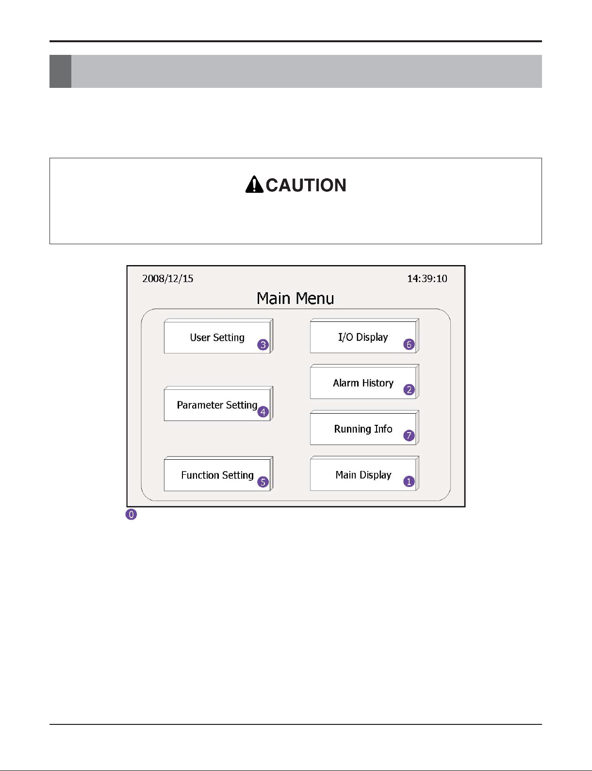
Menu structure of HMI machine is indicated Fig. 1 above. It consists of 7 menus about User interface. HMI is touch screen, and you can move to the menu you want if you click the menu item with
your hand. User Setting, Parameter Setting and Function Setting of menu limit is accessed by certification code system.
Especially Parameter Setting limits access of operator, and operator only has authority to access to
User Setting.
In case of approval after power is OFF, basically Main Display screen would show up and operator
can move to Main Menu by operating menu item.
Fig. 1

- 12 -
Chiller Water-cooled Screw
Main Display
Main Display consists of one screen, and it is the screen showing up when power is ON in the first
stage. Operator can check the present condition of chiller in Main display. Also, operator can start/stop
in main display. If pressing Start/Stop button on screen over 3 seconds, chiller may Start/Stop.
Operator can check the condition of pump and system in Main display.
If pump is ON, it means that it is operating and Pump State would be indicated as black oval. If
chiller is ON, it means that it is operating and System State would be flickering twice in a second.
Actual operating condition of pump can be different from Pump State indication depending upon
which part conduct the pump control. Pump state indication in the Fig. 2 above would be applied
when the pump is controlled by control signal of chiller.
Operator can check the present existence of alarm. It can be checked because there are indications
of kinds of alarm in the bottom of screen. When alarm is ON, alarm box on the top would be flickering twice in a second, and it can be eliminated by pushing the alarm box on the top. It would move
to Alarm display menu to eliminate it.
Operator can check the date and day on the top of the screen. The date and time is changeable
function of setting menu.
Temperature of cold water outlet and cooling water outlet would be indicated in the main display,
and operator can check the operation condition of chiller by checking the indication of temperature
sensor input on chiller.
Also, operator can check the cooling power of chiller when operating in main display. Cooling power
will be indicated as 0~100% by the result of actual compressor capacity control.
Fig. 2
- 13 -
Operation & Maintenance Manual
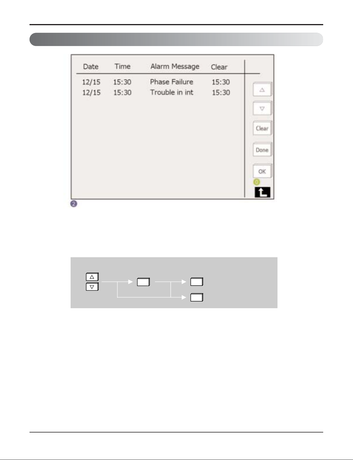
Alarm History
Last operated alarm will be indicated on Alarm display with time. Also, operator can cancel alarm on
the screen. See the Fig4 below for cancellation of alarm.
As explained in the Fig4 above, click the arrow ▽△ to move to the alarm contents which operator
wants to eliminate, and select the alarm by clicking OK. Cancel the alarm by clicking Clear.
Canceled alarm would be eliminated in the alarm display screen.
If operator does not cancel the alarm after alarm is ON, Chiller would not work even if actual alarm
situation is complete. After alarm is ON, always cancel the alarm and re-start it for operation.
Alarm elimination (Reset)
OK
Clear
Alarm elimination (Reset)
Done
Cancellation
Fig. 3
Fig. 4

- 14 -
Chiller Water-cooled Screw
User Setting
Fig. 5
- 15 -
Operation & Maintenance Manual
User setting consists of 2 screens. Movement can be done with clicking arrow ▽, △ Through user
setting, operator can make up the control parameter of chiller.
Operator basically can check and change the control setting condition of cold water outlet temperature. Among temperature setting items, target temperature of cold water outlet temperature and control range can be set by operator in user setting screen. Also by setting preheat function, operator
can set machine to operate only after ranged preheat time when power is ON.
For changing value, select the part which indicates the value and select the number which operator
wants to change to. If operator wants to cancel the change, select CLR, it would be cancelled. Stop
and Re-start temperature would be set automatically by setting Stop temperature Dt, Re-start Dt in
parameter setting. Stop temperature means the temperature at which compressor would be
stopped. Setting condition is 5.0ʼC. Re-start temperature means the temperature in case that compressor should be re-started after Stop. Setting condition is 9.0ʼC. Difference of Stop temperature
and Re-start temperature prevent often re-start of compressor.
Oil preheat can be set as Use/Nonuse, by minute unit. In the region where outdoor temperature is
low, oil needs to be preheated to ensure proper thickness of oil.
Control mode consists of Local Control/Tele Control, Hand Control/Auto control and MODBUS
Use/Nonuse. In case of Local Control, chiller may be operated by key controlling of operator. If
mode is changed to tele control, Start and Stop of chiller may be done by the condition of tele contact part.
In case of Auto control, chiller would Start and Stop automatically by operator setting operation
schedule. Schedule setting can be done in function setting menu. Contrarily, in case of Hand
Control, chiller would be operated by key control of operator or tele signals.
MODBUS would be used to conduct the control after connecting chiller to BMS and MODBUS
through network.
Operator can change password in second screen. Some function of HMI would be protected by
password. Password change can be done by selecting New Password , re-input it and complete it
by clicking OK.
Setting range of user setting value is specified below.
Table 1
Indication
Target Temp
Control Range
Preheat Function
Local Control/
Tele Control
Hand Control/
Auto Control
MODBUS
Code
Meaning
Setting temperature
of cold water outlet
Control Range
Preheat function
Local Control/
Tele control
Hand Control/
Auto Control
MODBUS Use
User input Password
Setting Range
5°C~12°C
0.6°C~1.5°C
Use/Nonuse
Local Control/
Tele Control
Hand Control/
Auto Control
Use/NonUse
XXXX
Basics
7°C
0.6°C
Use
Local Control
Hand Control
NonUse
6666
- 16 -
Chiller Water-cooled Screw
Function Setting
Fig. 6

- 17 -
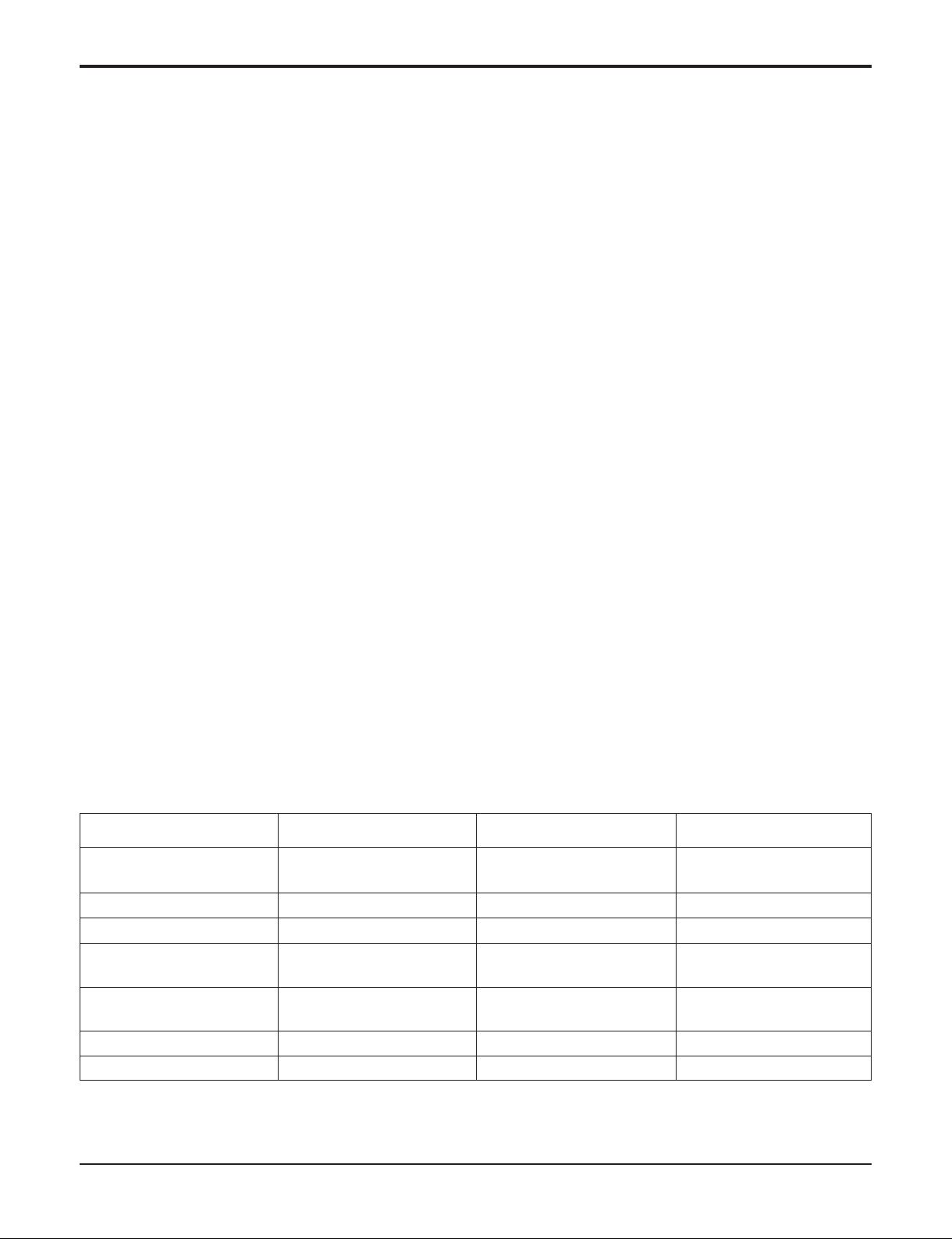
Operation & Maintenance Manual
Function setting menu consists of 3 screens, and screen movement can be done by using arrow ▽,
△.
Operator can set the present time in the first screen. It can be done by selecting date and time box
which operator wants.
Resting 2nd screens enable operator to set the operation schedule of chiller. In the second screen,
operator would set the period to operate the chiller. Input the first start date, time of chiller and input
the stop date and time. If operator inputs 00 for the time of operation, it means that it would not be
operated. It can be changed by selecting box as explained earlier. Setting operation schedule is
used for efficient process operation schedule setting of manufacturing facilities.
The last screen enable operator to set the operation schedule of chiller by a week unit. Input
detailed operation time schedule from Monday to Sunday. Time can be set in minute unit. If operator
inputs start and stop time as 00:00, it would not be operated. This operation schedule setting would
be efficient in the situation where load change happens often like in the normal office building.
In case that 2 schedules are overlapped, schedule in the second screen would take precedence
over the others.
- 18 -
Chiller Water-cooled Screw
I/O Display
- 19 -
Operation & Maintenance Manual
Fig. 7
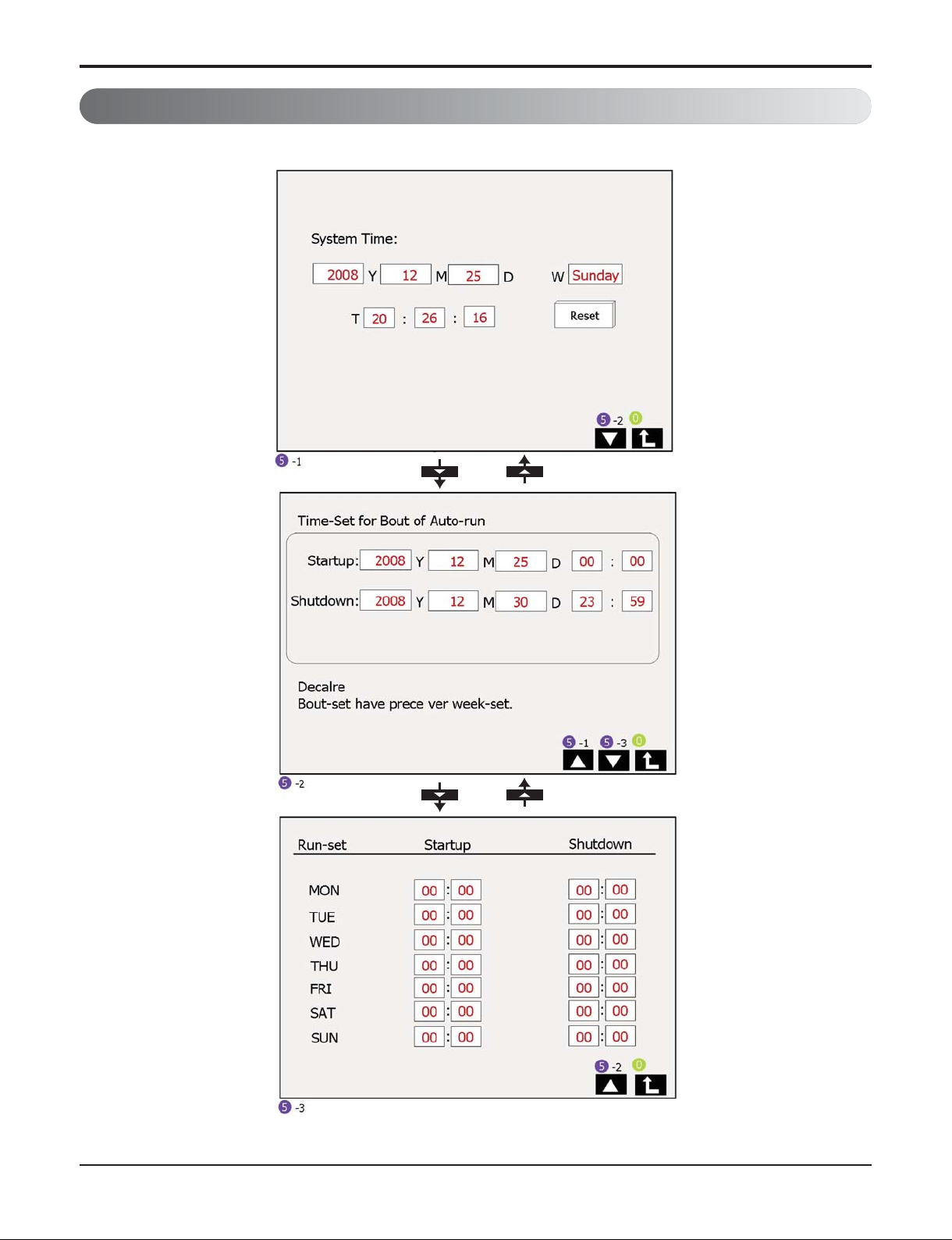
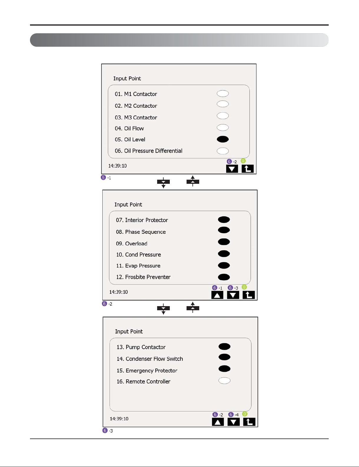
Input/Output display consists of total 5 screens including 3 screens for expressing the input condition and 2 screens for expressing the output condition. Input/Output display has input information
that means switch data that chiller control is inputted, and output information that means output signal approval of load equipment that conduct chiller controller output. Black oval of input/output signal means ON, white oval means OFF.
- 20 -
Chiller Water-cooled Screw
Indication value and meaning of input display, and normal value is specified above in the table.
Especially when operating if value is inputted other than the value specified above, PLC judge the wrong
value and alarm generated which would stop the chiller.
M3 contractor of input value is electron contactor of Y short of compressor motor and it would be change
to OFF after ON about for 5 seconds in the beginning of the compressor operation. After M3 Contactor is
Off, compressor would be operated normally through that M2 Contactor , which is electron contactor for
△ short. M1 contactor would be kept ON during operation as Main contactor for power approval.
Oil Flow and Oil Pressure Differential input would be inputted for checking normal function of lubrication
with Oil Level during operation. Oil level input always keeps being on during operation and stop which is
input for getting the oil level of oil separator. Oil Flow switch monitors actual oil flow from oil separator to
compressor, Oil Pressure differential is input for checking the pressure difference between low pressure
refrigerant and high pressure of compressor which is power for making oil flow, both inputs are ON when
compressor operation is stabilized. Therefore it check if it powers on normally in 5 minutes of compressor operation and it judge if it operates alarm. If it is not ON in 5 minutes of compressor operation, PLC
may recognize it alarm and stop the chiller safely.
Delay time is changeable through Parameter Setting, and contact LGE service agent when change is
needed because of alarm operation.
Table 2
Normal
Indication Meaning condition Normal condition
when when operating
stopping
M1 Contactor Main electron contactor ON ON
M2 Contactor Electron contactor for △ short OFF OFF → ON
M3 Contactor Electron contactor for Y short OFF ON → OFF
Oil Flow Oil flow switch OFF
ON
(in 5 minutes of operation)
Oil Level Oil Level switch ON ON
Oil Pressure Differential Oil Pressure differential switch OFF
ON
(in 5 minutes of operation)
Interior Protector Compressor interior protector ON ON
Phase Sequence Phase sequence voltage watcher ON ON
Overload Overload relay ON ON
Cond Pressure Condenser high-voltage switch ON ON
Evap pressure Evaporator low-voltage switch ON ON
Frosbite Preventer Freezing Preventer ON ON
Pump Contactor Pump operation input interlock OFF ON
Condenser Flow Switch Cold water/cooling water level switch OFF ON
Emergency Protector Emergency stop switch ON ON
Remote Controller Tele operation signal contact part ON/OFF ON/OFF
Input
- 21 -
Operation & Maintenance Manual
Compressor interior protector is equipment for sensing winding wire and discharge temperature of compressor which is installed on compressor. In case that compressor interior protector sense abnormal
high temperature from winding wire and discharge temperature, this signal change from ON to OFF, it is
kept ON in normal temperature condition.
Phase Sequence is Phase sequence voltage watcher which is installed on Power Panel, it watches input
power condition, if it detects abnormality, it change the signal from ON to OFF, if not it is in ON condition. The kinds of abnormal voltage that Phase Sequence can detect is 5, it includes over voltage, low
voltage, open, short, imbalance of between phase.
Overload is condition of overload relay for compressor, if it is normal it kept ON, if it is abnormal when
over-current flows it changes from ON to OFF.
Cond Pressure is input value of high-pressure switch that detect condenser high-pressure. It would be on in
high pressure abnormal condition, it would be On in normal pressure condition. Evap. Pressure also input
value of low-pressure switch that detects evaporator low-pressure. It would be OFF in evaporator low-pressure abnormal condition, it would be ON in normal pressure condition.
Frosbite Preventer is low temperature detect switch installed on evaporator, and it is used for preventing ice
formation. Low temperature detection would be done by the standard of cold water temperature 2ʼc, it would
be ON in normal temperature and it would be OFF if it is lower than 2ʼc.
Pump contactor input to the field wire is needed, contact part of electron contactor of cold water and cooling
water pump would be inputted to PLC in series. This signal should be ON when pump operation is needed.
Condenser Flow Switch is signal that is inputted into PLC after cold water and cooling water level switch
is connected in series. This signal should be ON when pump operation is needed.
Emergency Protector is the condition of Emergency switch that is installed on control. In case that emergency switch is cancelled, it is kept ON, in case that emergency switch is clicked, it is kept OFF.
Remote Controller is contact part signal input for tele controlling in tele control mode of chiller, when it is
ON, it operates chiller, when it is OFF, it stops chiller.
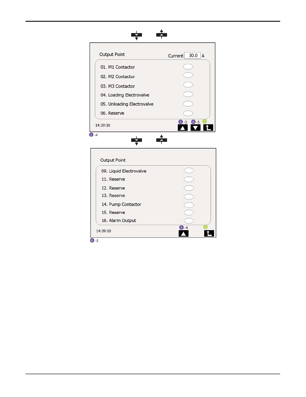
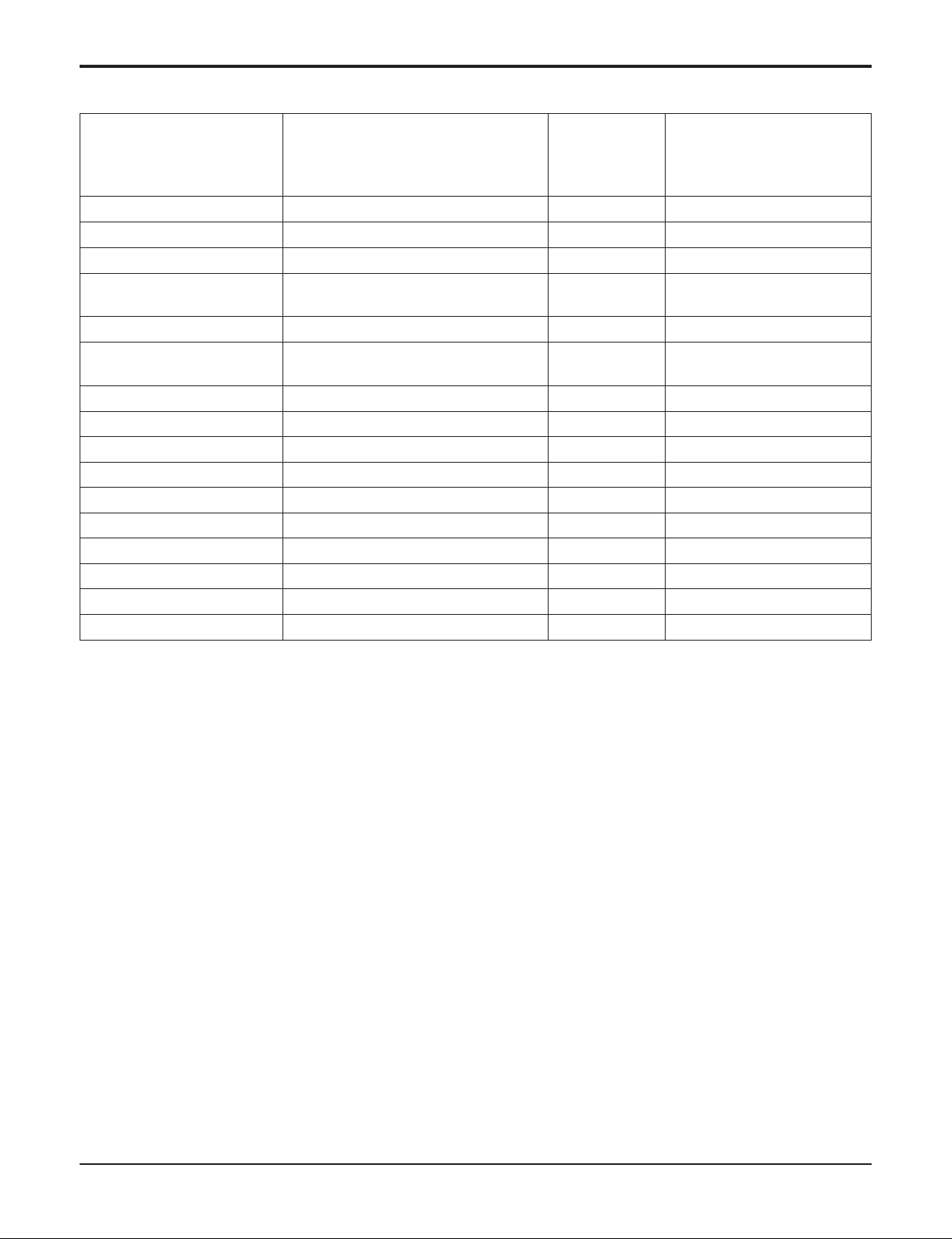
Table 3
Normal
Indication Meaning condition Normal condition
when when operating
stopping
Current Operation Current 0A Operation Current
M1 Contactor Main electron contactor ON ON
M2 Contactor Electron contactor for △ short OFF OFF → ON
M3 Contactor Electron contactor for Y short OFF ON → OFF
Loading Solenoid valve
Control valve for Sliding It changes depending on operation
Unloading Valve condition.
Solenoid valve
Liquid Solenoid valve Valve for Economizer ON
OFF/ON
(100% ON during operation)
Pump Contactor Pump control OFF ON
Alarm Output Alarm operation It changes depending on operation condition.
Output

- 22 -
Chiller Water-cooled Screw
M1 contactor, M2 contactor and M3 contactor indicates condition of electron contactor for compressor with input display. The value indicated on Output display is Output from actual PLC, the value
indicated on Input display is extra contact part condition which is inputted to PLC from electron contactor. Therefore, if wiring related to electron contactor is normal, the condition should be consistent.
If input condition and output condition is not same due to abnormality of electron contactor, it recognize the situation of alarm generation by PLC.
Loading Solenoid valve and Unloading Solenoid valve is used to control the sliding valve for volume
control of the compressor. Loading Valve and Unloading Valve is used to control Sliding Valve by
using oil pressure for compressor.
Liquid Solenoid valve is valve for Economizer operation, and it is installed at the pipe that sprays the
mid-pressure refrigerant to middle of compressor rotor, and it sprays when it is ON. If it is normal,
Liquid Solenoid valve is ON and spray refrigerant 100% in operating condition.
Pump contactor output is output signal for control cold water and cooling water, it should conduct
pump control of cold water and cooling water pump in field by field wiring. At least field pump should
be kept operating when this output signal is ON.
Alarm Output is the signal that operator can check the alarm operation of chiller in location where it
is far from chiller installation field and gives output when alarm is ON. If this signal is ON, chiller has
alarm operation, if the signal is OFF, chiller has normal condition.
- 23 -
Operation & Maintenance Manual
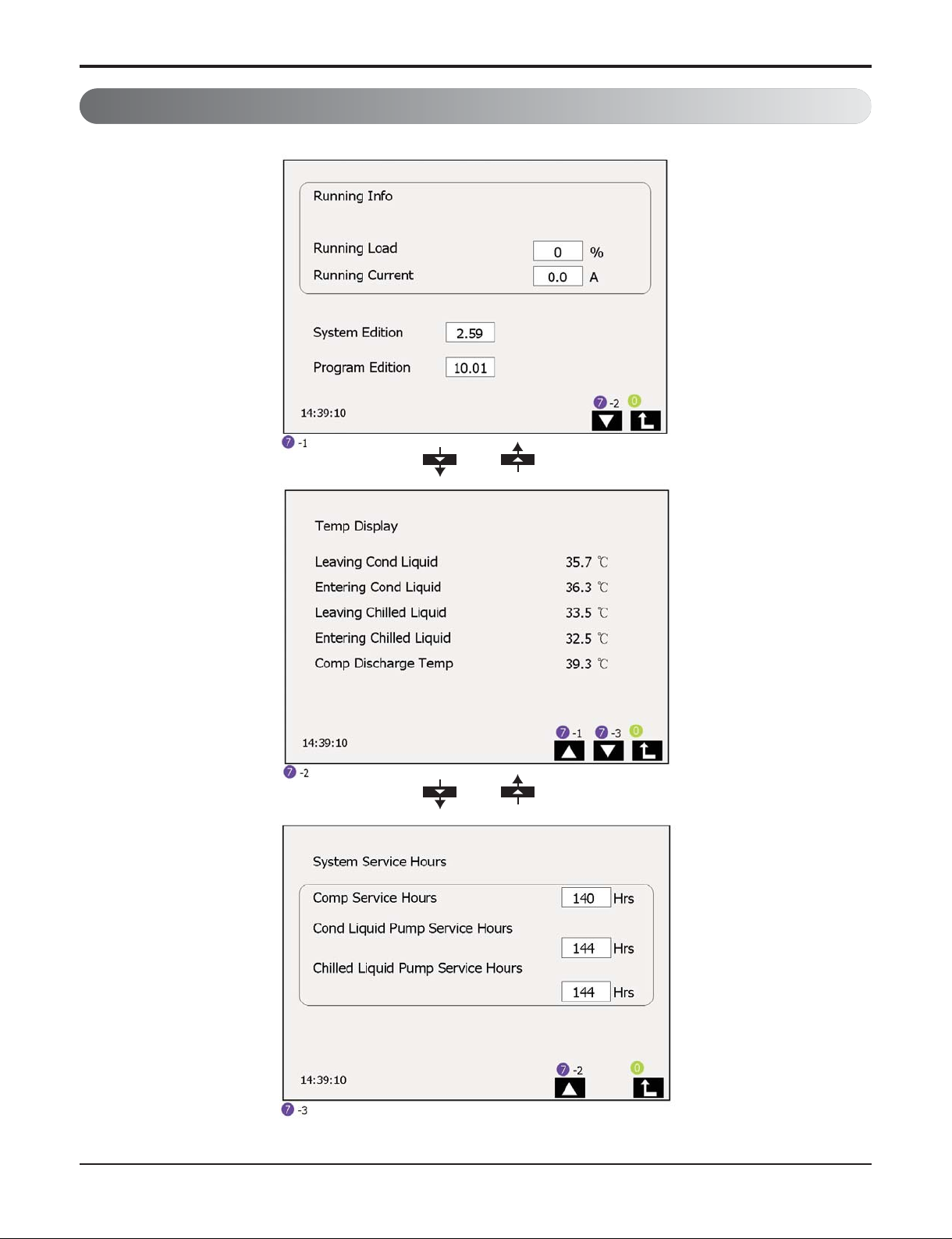
Running Information
Fig. 8

- 24 -
Chiller Water-cooled Screw
Operation Information screen indicates operation value state of chiller including chilling cycle, cold
water/cooling water temperature.
This operation value state includes chiller operation capability and operation current in present condition, also does accumulate operation time of cold water, cooling water pump and compressor.
Also, operation value state indicates refrigerant temperature of chilling cycle and cold water, cooling
water temperature. Indicated temperature would be shown to one place of decimal, and it includes
Leaving Cond. Liquid, Entering Cond. Liquid, Leaving Chilled Liquid, Entering Chilled Liquid, and
Comp. discharge Temp.
 Loading...