

RCWW008CA1B,RCWW010CA1B,RCWW011CA1B,RCWW012CA1B,RCWW014CA1B,RCWW016CA1B,RCWW018CA1B,RCWW020CA1B,RCWW022CA1B,RCWW020CA2B,RCWW022CA2B,RCWW024CA2B,RCWW026CA2B,RCWW028CA2B,RCWW032CA2B,RCWW036CA2B,RCWW040CA2B,RCWW044CA2B,RCWW008CA1B,RCWW010CA1B,RCWW011CA1B,RCWW012CA1B,RCWW014CA1B,RCWW016CA1B,RCWW019CA1B,RCWW020CA2B,RCWW022CA2B,RCWW024CA2B,RCWW028CA2B,RCWW032CA2B,RCWW038CA2B
LG RCWW008CA1B,RCWW010CA1B,RCWW011CA1B,RCWW012CA1B,RCWW014CA1B,RCWW016CA1B,RCWW018CA1B,RCWW020CA1B,RCWW022CA1B,RCWW020CA2B,RCWW022CA2B,RCWW024CA2B,RCWW026CA2B,RCWW028CA2B,RCWW032CA2B,RCWW036CA2B,RCWW040CA2B,RCWW044CA2B,RCWW008CA1B,RCWW010CA1B,RCWW011CA1B,RCWW012CA1B,RCWW014CA1B,RCWW016CA1B,RCWW019CA1B,RCWW020CA2B,RCWW022CA2B,RCWW024CA2B,RCWW028CA2B,RCWW032CA2B,RCWW038CA2B User Manual
Page 1
LG Electronics, Home appliance & Air solution company
56, Digital-ro 10-gil, Geumcheon-gu, Seoul, Republic of Korea (153-801)
www.lg.com
www.lgeaircon.com
Ver. 202004
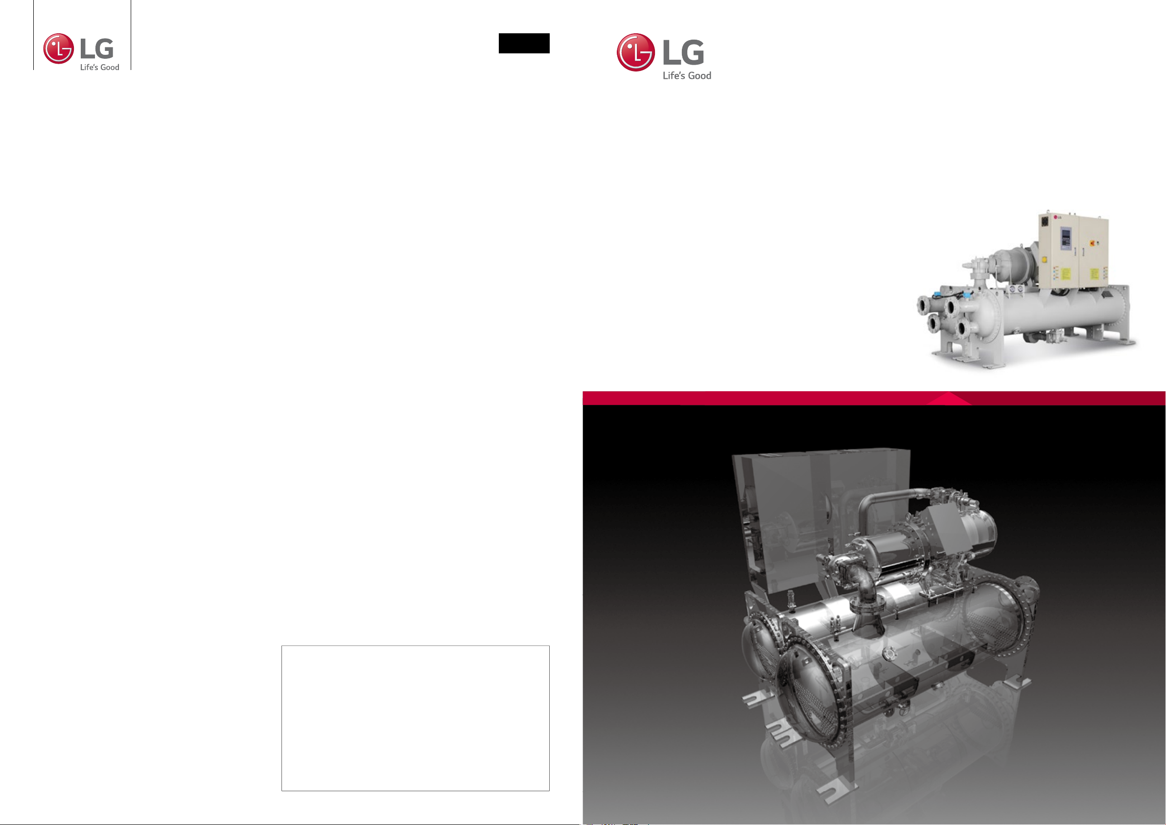
LG HVAC SOLUTION
WATER COOLED
SCREW CHILLER
For continual product development, LG reserves the right to
change specifications or designs without notice.
© 2020 LG Electronics. Printed in Korea. Apr. 2020
Distributed by
Page 2
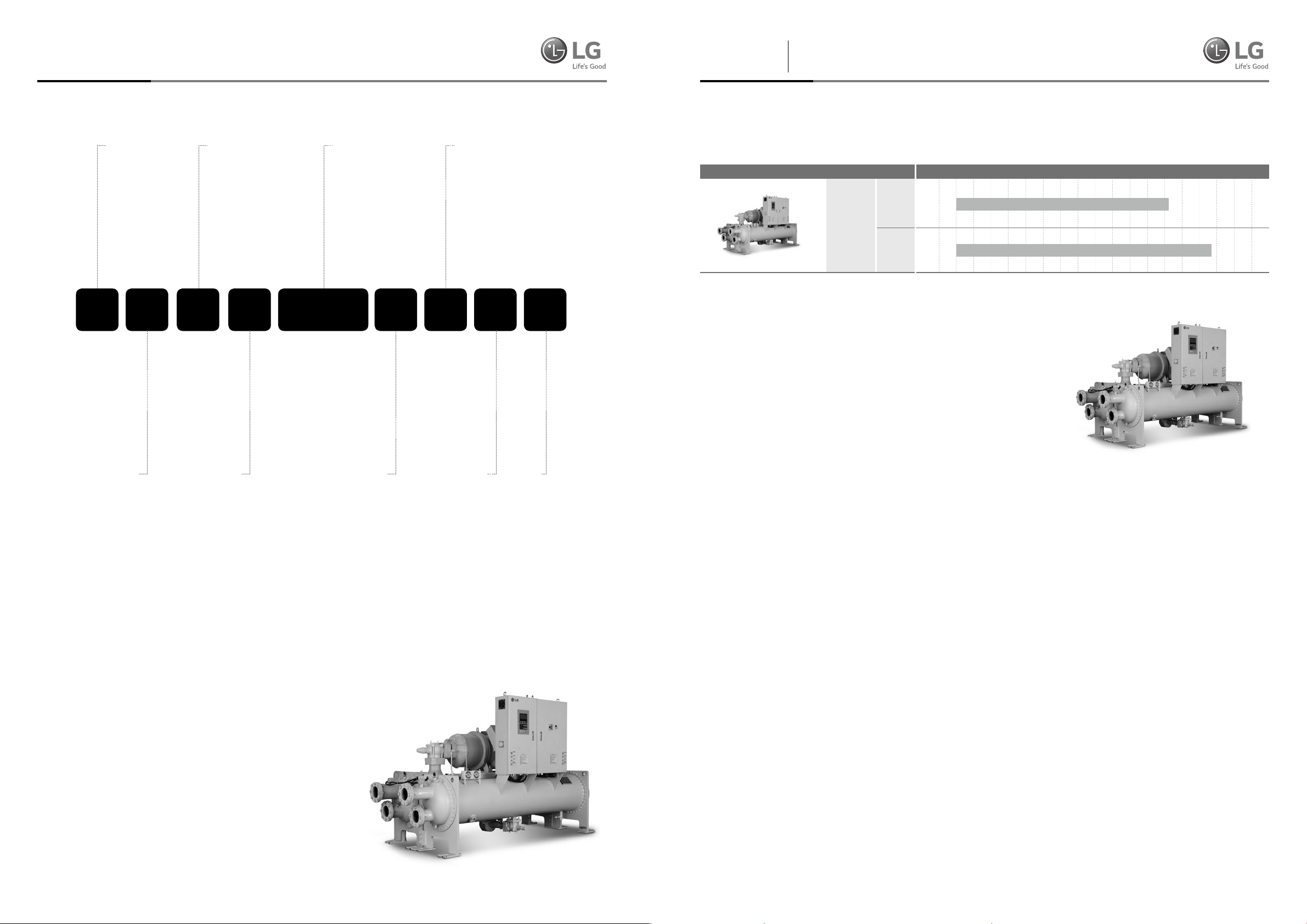
Line upNomenclature
Introduction
R : Korea(R134a)
M : China(R134a)
C: Chiller
Contents
02 Nomenclature
03 Line up & Introduction
04 Equipment overview
06 Control
08 Accessories and options
09 Specication
15 Electrical data
22 Outline drawing
24 Foundation
26 Piping diagram
28 Control wiring
30 Power wiring
32 Installation
34 Guide specication
W: Water-cooled
(Cooling only)
W: Screw
compressor
Nominal ton:
100RT ⇨ 010
380RT ⇨ 038
Water working pressure:
A: Chilled water : 10kgf/cm²G
Cooling water : 10kgf/cm²G
B: Chilled water : 16kgf/cm²G
Cooling water : 16kgf/cm²G
C: Chilled water : 20kgf/cm²G
Cooling water : 20kgf/cm²G
030R C W W C A 2 B
Develop-
A: Flooded type
C: Falling film type
Number of
compressors
ment
sequence
Line up
Model
50Hz
R-134a
60Hz
LG’s latest Water cooled screw chiller offers excellent operational efciency
thanks to the company’s advanced technologies and unrivalled air conditioning
expertise. The new model’s advanced capacity control system valve help to
improve performance and efciency. LG’s proprietary PID(Proportional, Integral,
Differential control), which controls hydraulic-head loss rate, helps to minimize
energy loss even further.
• High-performance compressor manufactured by specialized
manufacturer is adopted to ensure that the chiller is
economical and durable with low vibration and low noise.
• Highly integrated motherboard is adopted and hence the
function is strong and reliable.
• Advanced control algorithm is adopted to control chiller in
advance and hence avoid frequent stoppage protection of chiller.
• We have set complete safety protection function in order to
make chiller safely and reliably run.
• The linkage control and remote monitoring function of
peripheral equipment ensure that the chiller can run safely
and the operation and monitoring are convenient.
• The selection of excellent raw materials and ttings is the key
to guaranteeing chiller quality.
High efciency, High reliability
The RCWW & MCWW series is a kind of water-cooled spray
screw chiller produced by LGE Corporation. Because of the
special structure design, the chiller has high efciency and
high reliability.
Optimized dedicated motor
R134a with high efciency
Made of premium grade, low-loss core steel with the special
slot design, the motors of R134a dedicated compressors
50 100 150 200 250 300 350 400 450 500
75RT 380RT
75RT 440RT
can gain the highest efciency with low power consumption.
Besides, different winding for specic voltage and frequency
requirement contributes to the best power factor and
excellent performance.
Constructional design of
dedicated screw compressor
The screw compressor is characterized by a very compact
design. Most of inner dimensions have been totally modied
considering displacement volume, size of compression
chamber, length & prole of rotors, oil separator specication
and oil piping rearrangement, etc. to ensure consistency and
cost effectiveness of the compressor.
Compressor
• Semi-hermetical twin-rotor screw compressor.
• Direct-drive, low speed/RPM for high efciency and high reliability.
• Only three moving parts, resulting in high reliability with
simple solution.
• Field serviceable compressor and easy maintenance.
• Precise rotor tip clearance.
• The world’s advanced patent screw tooth with low noise,
smooth operation long life advantages.
• A refrigerant dispersing cooling device is set internally for
compressor cooling, which uses return-refrigerant cooling.
• Years of research and testing. The LG screw chiller has
amassed thousands of hours of testing, and conditions
* The above range is based on the nominal tonnage.
02 | 2020 LG Water Cooled Screw 2020 LG HVAC Solution | 03
Page 3
Features Features
Equipment overviewEquipment overview
beyond normal air conditioning applications.
Unit performance testing
LG began promoting factory performance tests for air-cooled
chillers and water-cooled chillers, to show we stand behind the
products we design and build.
The bene ts of a performance test include veri cation of performance, prevention of operational problems, and assurance of a
smooth start-up.
Only a performance test conducted in a laboratory or laboratory
grade facility will con rm both performance and operation of a
speci c chiller.
Mostly factory performance tests go smoothly. If a problem
occurs, LG personnel easily correct them and chiller is shipped
to job site.
When a factory performance test is requested, the test can be
conducted at the speci ed, design conditions. The test facility
has the capability to control ambient test conditions to assure
our customers that our chillers will perform as predicted.
AHRI certi cation program
and standards and codes
Chillers conform to the following Standards and Codes:
• AHRI 550/590 - water chilling
packages using the vapor
compression cycle.
• ANSI/ASHRAE 34 -
number designation and safety
classi cation of refrigerants.
• ASME Section VIII(Option) - boiler and pressure vessel.
• GB/T 18430.1 - water chilling(heat pump) packages using the
vapor compression cycle - part 1: water chilling(heat pump)
packages for industrial & commercial and similar applications.
(This code is only applied to product manufactured in China)
Equipment Overview
Semi-hermetic twin compressor
The semi-hermetic screw compressor is developed especially
for applications in air-conditioning and refrigeration. With high
operating load design, each compressor is of high ef ciency
and reliability in all operating conditions. Each compressor has
the latest and advanced 5-to-6 Patented Screw Rotor Pro le
designed to ensure high capacity and ef ciency in all operating
conditions.
The compressor is equipped with separated radial and axial
bearings, liquid injection and economizer connection, PTC
motor temperature thermistors and discharge temperature
thermistors, a motor protector, and oil level switch and
oil pressure differential switch and other accessories. The
complete accessories and their new designs guarantee the
compressor has the best reliability, longest bearing life during
heavy duty running and strict operating conditions.
The slide valve for capacity control is located in the compressor
chamber. The slide valve is actuated by injection of pressurized
oil into the cylinder from the oil sump as well as bypass of
oil through solenoid valves in each oil lines with pressure
differential.
The screw compressors are equipped with either 3-step/4step capacity control system or continuous(stepless) capacity
control system. Both of the capacity control systems consist
of a modulation slide valve, piston rod, cylinder, piston and
piston rings. The slide valve and the piston are connected by a
piston rod. The principle of operation is using the oil pressure
to drive the piston in the cylinder. The lubrication oil ows from
the oil sump through the oil lter cartridge and capillary then
lls into the cylinder due to the positive oil pressure bigger
than the right side of spring force plus the high pressure
gas. The positive pressure differential causes the piston to
move toward the right side in the cylinder. When the slide
valve moves toward the right side, the effective compression
volume in the compression chamber increases. This means the
displacement of refrigerant gas also increases, as a result the
refrigeration capacity also increases.
However, when any of the step solenoid valve(for 4-step
capacity control system) is opened, the high pressure oil in the
cylinder bypasses to the suction port, which causes the piston
and the slide valve to move toward the left side, and then
some of the refrigerant gas bypasses from the compression
chamber back to the suction end. As a result, the refrigeration
capacity decreases because of the reduction of displacement
of refrigerant gas owing in the system. The piston spring
is used to push the piston back to its original position, i.e.
minimum load position in order to reduce the starting current
for the next starting.
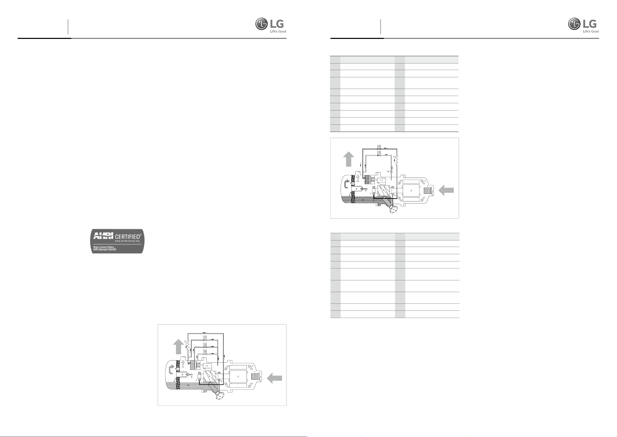
4-steps capacity control
Component
No
1 Suction filter 10 Lubricant
2
Gas in(low pressure) 11 Oil separator cartridge
Motor 12
3
4 Oil filter cartridge 13 Capillary
5 Suction bearings 14 Solenold valve, SV2
6 Male rotor 15 Solenold valve, SV1
7 Discharge bearings 16 Orifice
8 Oil separator baffle 17 Slide valve
9
Gas out(high pressure with oil)
Step-less capacity control
Component
No
1 Suction filter 10 Lubricant
2 Gas in(low pressure) 11 Oil separator demister
3 Motor 12 Gas out(high pressure without oil)
4 Oil filter cartridge 13 Capillary
5 Suction bearings 14
6 Male rotor 15
7 Discharge bearings 16
8 Oil separator baffle 17 Slide valve
9 Gas out(high pressure with oil) *
Component
No
Gas out
(high pressure without oil)
Component
No
Solenold valve(min. %),
SV 25% / 33%
Solenold valve
(50% of full load), SV 50%
Solenold valve(75% / 66% of
full load), SV 75% / 66%
For RC2-100, 140 & 180 the SV50% omitted
Heat exchanger
Evaporator
Falling lm type
“Falling lm” shell and tube type evaporator having refrigerant
in the shell and chilled water inside the tubes.
Advantage of this type evaporator is higher heat transfer
performance and reduced refrigerant charge.
Distributer located on the top side of inside shell makes
uniform ow of refrigerant, this refrigerant ows downward
by gravity as a continuous lm.
The shell is of welded carbon steel construction with steel
tube sheets and copper heat exchange tubes. Removable steel
water boxes at both ends of the cooler allow tube cleaning
without disturbing the refrigerant circuit.
Tubes are mechanically expanded into tube sheets with double
grooves to ensure leak tight and trouble free operation.
Multiple compressor/ circuit chillers have coolers with separate
refrigeration circuits for each compressor.
Each refrigeration circuit is provided with its own pressure
relief valve. All chillers are tted with drain valves on the
removable heads and shell. All coolers are factory insulated
with 19mm of closed cell expanded synthetic rubber with all
joints vapor sealed.
Expansion device
Expansion unit consists of butter y valve and ori ce. At 100%
load situation, the pressure loss at the ori ce is smaller than
the refrigerant pressure loss in the condenser, thus the super-
cooled refrigerant passes through the ori ce.
At this stage the maximum amount of refrigerant is owing
into the evaporator. As the load reduces gradually, the
circulating amount of refrigerant also reduces and accordingly
the refrigerant level in the condenser is getting low.
When the amount of liquid refrigerant reduces, the gas
amount in the ori ce is getting larger, raising the resistance
thus controlling the ow rate.
Control
Controller system information
Generally controller consist of Display, Master, Slave and Relay
board. Each board connect with RS485 communication and
include analog input/output, digital input/output channel.
• 7 and 10.2-inch color LCD touch screen with high resolution
(1,024 x 600)
• Operation scheduling function
• Real time trend display
• Web Access(Additional accessory)
• Running data acquisition
• Easy-to-read display of operational data
• Certi ed EMI/EMS
• Communication supported: Modbus, RS485(standard)
• Language: English / Chinese / Korean
04 | 2020 LG Water Cooled Screw 2020 LG HVAC Solution | 05
Page 4
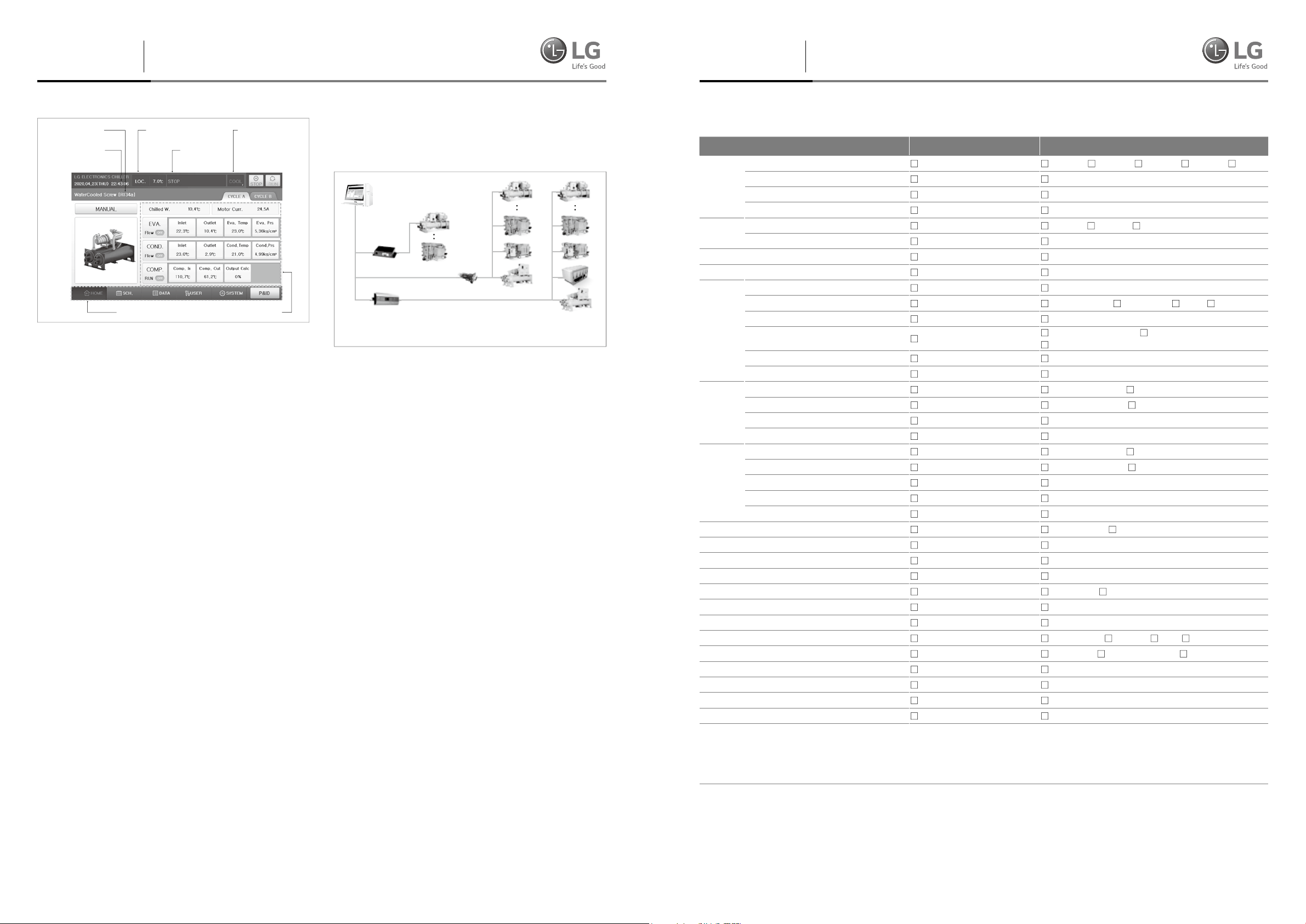
Features
Control
Features
Accessories and options
①
Machine type
selection indicator
②
Date and time
indicator
⑦
Menu bar
③
Operation method
selection indicator
④
Message
display
⑤
Operation mode
selection indicator
⑥
Displayed categories
Controller front view
① Machine type selection indicator
It show the currently selected model. You can check detail
from 'Control Information set' part.
② Date and time indicator
It show the current time. You can check detail from 'Sys.
Info.(System information)' part.
③ Operation method selection indicator
It show the currently selected control mode. You can
check detail from 'User set' part.
④ Message display
It show the message about status of product.
⑤ Operation mode selection indicator
It show the currently selected run mode. You can check
detail from 'User set' part.
⑥ Displayed categories
It show the currently information of product.
⑦ Menu bar
It show the functions for menu operation button.
Features of control unit
The Control unit of LG chiller controls temperature, pressure,
current and capacity control valve using high capacity
microprocessor. It is constructed to provide the high reliability
chiller operation using LG's unique optimum control algorithm.
Controller system composition diagram
Master board and slave board have the same hardware and
they are set as master or slave by DIP switch setting. This
board consist of analog input/output, digital input/output and
communication connections.
• Protocol and communication method
- Standard : Modbus, RS-485
- Option : BACnet, TCP/IP, Lonwork
RS485
TCP/IP
Serial to LAN
converter
Protocol
converter
The chillers can be managed up to 255 units when using communication of RS485 or TCP/IP.
Multi-Drop
RS485
Converter
Connecting to max 8 units
Detailed diagrams of BMS
NFB(Non-Fused Breaker)
power disconnect switch
A non-fused disconnect is available as a factory-installed option
for all units with single point power connection units. This option
is that power supply is disconnected during service & repair.
Suction service isolation valve
Service suction isolation valve is installed with unit for each
refrigerant circuit as a standard.
General options
Vibration isolation
For installation on building roofs or in sensitive noise areas
(hospitals, studios and some residential areas) pre-selected
spring type isolators with 1” or 2” de ection are available as a
factory option – shipped loose part for eld installation.
Power factor correction
Provide equipment with power factor correction capacitors as
required to maintain a displacement power factor of 95% at all
load conditions.
Water-Cooled Screw chiller standard summary
Items Standard Option
Power Supply(3Ph)
Comp.
Control
Panel
Power Connection
Factory Wiring
Starter
Panel
EVAP.
COND.
Refrigerant Charge
Packing
Insulation
Sound attenuator
Isolation
Anchor Bolt for Foundation
Counter Pipe Flange
Certification
Factory Performance Test&Process inspec.
Operating Training
Warranty-Compressor
Warranty-Ass'y
Labor warranty
Standard specification
Hertz
Capacity Control type
Angle Valve
Communication
Protection Grade
Supplied by
Starter type
Mounted type
Misc. Options
Power Access
Protection Grade
Waterbox Pressure
Nozzle Type
Flow proof type(Ref.)
Pipe direction(C.B Front st.)
Waterbox Pressure
Nozzle Type
Flow proof type(Water)
Flow proof type(Ref.)
Pipe direction(C.B Front st.)
380V
50Hz
Step
N/A
Modbus
IP4X
Standard(Single)
Open Wiring
Factory
Y-Delta(Open)
Unit Mounted
N/A
From the Top
IP4X
150psig(10kg/cm
ANSI-Flange
Relief V/V(Single)
Left
150psig(10kg/cm
ANSI-Flange
N/A
Relief V/V(Single)
Left
Separated Shipping
Shrink film
Yes
N/A
Neoprene PAD
N/A
N/A
Standard(KGS)
N/A
N/A
1yr
1yr
N/A
1) Factory Wiring : Open Wiring
2) Color : Dawn Gray
- Starter / Control Panel : Warm Gray
3) Standard provide Emergency stop switch
4) Flow proof type : DP Switch(Evaporator)
400V 415V 440V 460V 480V
60Hz
Stepless
Yes
BACnet TCP/IP etc( )
etc( )
Multi power Connection
Flexible Wiring
Supplied by customer
Y-Delta(Closed) Soft Starter
Stand Alone
Ground Fault Protection Power Factor Correction Capacitor
Integrating Watt-meter
From the Bottom
etc( )
2
)
2
)
230psig(16kg/cm
ANSI-Victaulic(AGS) ANSI-Victaulic(OGS)
Relief V/V(Dual)
Right
230psig(16kg/cm
ANSI-Victaulic(AGS) ANSI-Victaulic(OGS)
DP switch
Relief V/V(Dual)
Right
Factory Charge Customer supplied
Wooden packing
N/A
Yes
Spring 1Inch Spring Rubber Pad
Yes
Yes
ASME Ⅶ Only CE(PED) PED (C)UL(ETL)
Report Only Customer Wintness Process inspection
Yes
etc( )
etc( )
etc( )
2
)
2
)
300psig(20kg/cm
300psig(20kg/cm
SPG
Direct
2
2
)
)
BMS support function
Screw chiller’s basic communication protocol is Modbus protocol,
and it is compatible with the higher level communication methods.
Communication protocol support
06 | 2020 LG Water Cooled Screw 2020 LG HVAC Solution | 07
Page 5
Specification
60Hz
Specification
60Hz
R134a(60Hz)
Model Units RCWW008CA1B RCWW010CA1B RCWW011CA1B RCWW012CA1B RCWW014CA1B
AHRI
Condition
Number of Circuits 1 1 1 1 1
General Unit
Data
Weight
Compressors
Condenser
Evaporator
Dimension
Operating Weight kg 2,810 3,020 3,120 3,120 3,460
Water Connections DN 100 100 100 100 125
Water Connections DN 100 100 100 100 125
Cooling capacity
Input Power kW 51.6 62.3
COP 5.35 5.33 5.34 5.35 5.58
Refrigerant,
R-134a
Oil Charge l 16 16 18 20 20
Shipping Weight kg 2,670 2,860 2,950 2,940 3,230
Compressor type Semi-hermetic twin screw
Quantity EA 1 1 1 1 1
Condenser type Shell and Tube
Max. Water
Pressure
Max. Refrigerant
Pressure
Min. Cooling
Water Flow Rate
Max. Cooling
Water Flow Rate
Evaporator type Shell and Tube
Max. Water
Pressure
Max. Refrigerant
Pressure
Min. Chilled
Water Flow Rate
Max. Chilled
Water Flow Rate
Length mm 3,040 3,040 3,040 3,040 3,145
Width mm 1,435 1,435 1,435 1,435 1,480
Height mm 1,860 1,865 1,865 1,865 2,080
kW 276.0 332.2 376.4 407.0 472.2
usRT 78.5 94.5
107.0
70.5
kg 110 110 110 110 140
MPa 1.0 1.0 1.0 1.0 1.0
MPa 1.0 1.0 1.0 1.0 1.0
l/s 6.6 7.5 8.5 8.5 10.8
l/s 26.5 30.0 34.2 34.2 43.2
MPa 1.0 1.0 1.0 1.0 1.0
MPa 0.9 0.9 0.9 0.9 0.9
l/s 5.6 7.7 7.7 8.4 10.1
l/s 22.3 30.7 30.7 33.5 40.5
115.7 134.3
76.1 84.7
R134a(60Hz)
Model Units RCWW016CA1B RCWW018CA1B RCWW020CA1B RCWW022CA1B RCWW020CA2B
AHRI
Condition
Number of Circuits 1 1 1 1 2
General Unit
Data
Weight
Compressors
Condenser
Water Connections DN 125 125 125 125 150
Evaporator
Water Connections DN 125 125 125 125 150
Dimension
Cooling capacity
Input Power kW 105.0 114.7
COP 5.44 5.52 5.47 5.61 5.35
Refrigerant,
R-134a
Oil Charge l 28 28 28 1 16 / 16
Shipping Weight kg 3,560 3,680 3,780 3,880 5,140
Operating Weight kg 3,810 3,960 4,060 4,160 5,410
Compressor type Semi-hermetic twin screw
Quantity EA 1 1 1 1 2
Condenser type Shell and Tube
Max. Water
Pressure
Max. Refrigerant
Pressure
Min. Cooling
Water Flow Rate
Max. Cooling
Water Flow Rate
Evaporator type Shell and Tube
Max. Water
Pressure
Max. Refrigerant
Pressure
Min. Chilled
Water Flow Rate
Max. Chilled
Water Flow Rate
Length mm 3,145 3,145 3,145 3,365 3,855
Width mm 1,480 1,605 1,605 1,750 1,565
Height mm 2,080 2,105 2,105 2,150 2,175
kW 571.6 632.8 681.1 795.9 667.6
usRT 162.6 180.0
193.7
124.6
kg 140 165 165 200 120 x 2
MPa 1.0 1.0 1.0 1.0 1.0
MPa 1.0 1.0 1.0 1.0 1.0
l/s 12.0 13.6 13.6 13.6 12.0
l/s 48.1 54.4 54.4 54.4 48.1
MPa 1.0 1.0 1.0 1.0 1.0
MPa 0.9 0.9 0.9 0.9 0.9
l/s 11.2 12.6 12.6 12.6 11.2
l/s 44.6 50.2 50.2 50.2 44.6
226.4 189.8
142.0 124.7
Note:
1. 1usRT = 3,024kcal/hr = 3.517kW, 1mH
2. AHRI conditions :
Leaving chilled water temperature is 6.7 ˚C(44 ˚F). Water flow is 0.043 L/s per kW(2.4 gpm/ton)
Entering cooling water temperature is 29.4 ˚C(85 ˚F). Water flow is 0.054 L/s per kW(3.0 gpm/ton)
Fouling factor of water in evaporator is 0.018 m²·˚C/kW(0.00001 h·ft2·˚F/Btu)
Fouling factor of water in condenser is 0.044 m²·˚C/kW(0.00025 h·ft2·˚F/Btu)
3. Due to our policy of innovation some specification may be changed without prior notification.
O = 9.8kPa
2
08 | 2020 LG Water Cooled Screw 2020 LG HVAC Solution | 09
Page 6

Specification
60Hz
Specification
60Hz
R134a(60Hz)
Model Units RCWW022CA2B RCWW024CA2B RCWW026CA2B RCWW028CA2B RCWW032CA2B
AHRI
Condition
Number of Circuits 2 2 2 2 2
General Unit
Data
Weight
Compressors
Condenser
Evaporator
Dimension
Operating Weight kg 5,780 5,940 6,080 6,150 7,040
Water Connections DN 150 150 150 150 200
Water Connections DN 150 150 150 150 200
Cooling capacity
Input Power kW 140.9 152.4
COP 5.35 5.34 5.38 5.56 5.42
Refrigerant,
R-134a
Oil Charge l 18 / 18 20 / 20 23 / 23 20 / 20 28 / 28
Shipping Weight kg 5,460 5,600 5,720 5,770 6,580
Compressor type Semi-hermetic twin screw
Quantity EA 2 2 2 2 2
Condenser type Shell and Tube
Max. Water
Pressure
Max. Refrigerant
Pressure
Min. Cooling
Water Flow Rate
Max. Cooling
Water Flow Rate
Evaporator type Shell and Tube
Max. Water
Pressure
Max. Refrigerant
Pressure
Min. Chilled
Water Flow Rate
Max. Chilled
Water Flow Rate
Length mm 3,855 3,855 3,855 3,855 3,855
Width mm 1,565 1,565 1,565 1,685 1,685
Height mm 2,175 2,175 2,175 2,225 2,225
kW 754.6 814.0 886.8 945.3 1,141.1
usRT 214.6 231.5
252.2
164.7
kg 120 x 2 120 x 2 120 x 2 145 x 2 145 x 2
MPa 1.0 1.0 1.0 1.0 1.0
MPa 1.0 1.0 1.0 1.0 1.0
l/s 13.6 14.6 14.6 16.9 19.0
l/s 54.4 58.6 58.6 67.7 76.0
MPa 1.0 1.0 1.0 1.0 1.0
MPa 0.9 0.9 0.9 0.9 0.9
l/s 12.6 13.8 13.8 15.7 18.0
l/s 50.2 55.1 55.1 62.8 71.8
268.8 324.5
169.9 210.5
R134a(60Hz)
Model Units RCWW036CA2B RCWW040CA2B RCWW044CA2B
AHRI
Condition
Number of Circuits 2 2 2
General Unit
Data
Weight
Compressors
Condenser
Water Connections DN 200 200 200
Evaporator
Water Connections DN 200 200 200
Dimension
Cooling capacity
Input Power kW 230.0 249.8 284.7
COP 5.51 5.44 5.58
Refrigerant,
R-134a
Oil Charge l 28 / 28 28 / 28 28 / 28
Shipping Weight kg 6,910 6,930 7,430
Operating Weight kg 7,430 7,480 7,980
Compressor type Semi-hermetic twin screw
Quantity EA 2 2 2
Condenser type Shell and Tube
Max. Water
Pressure
Max. Refrigerant
Pressure
Min. Cooling
Water Flow Rate
Max. Cooling
Water Flow Rate
Evaporator type Shell and Tube
Max. Water
Pressure
Max. Refrigerant
Pressure
Min. Chilled
Water Flow Rate
Max. Chilled
Water Flow Rate
Length mm 4,550 4,550 4,550
Width mm 1,795 1,795 1,910
Height mm 2,275 2,275 2,300
kW 1,267.5 1,357.7 1,589.0
usRT 360.5 386.1 451.9
kg 165 x 2 165 x 2 190 x 2
MPa 1.0 1.0 1.0
MPa 1.0 1.0 1.0
l/s 21.6 21.6 21.6
l/s 86.5 86.5 86.5
MPa 1.0 1.0 1.0
MPa 0.9 0.9 0.9
l/s 20.2 20.2 20.2
l/s 80.9 80.9 80.9
Note:
1. 1usRT = 3,024kcal/hr = 3.517kW, 1mH
2. AHRI conditions :
Leaving chilled water temperature is 6.7 ˚C(44 ˚F). Water flow is 0.043 L/s per kW(2.4 gpm/ton)
Entering cooling water temperature is 29.4 ˚C(85 ˚F). Water flow is 0.054 L/s per kW(3.0 gpm/ton)
Fouling factor of water in evaporator is 0.018 m²·˚C/kW(0.00001 h·ft2·˚F/Btu)
Fouling factor of water in condenser is 0.044 m²·˚C/kW(0.00025 h·ft2·˚F/Btu)
3. Due to our policy of innovation some specification may be changed without prior notification.
O = 9.8kPa
2
10 | 2020 LG Water Cooled Screw 2020 LG HVAC Solution | 11
Page 7

Specification
50Hz
Specification
50Hz
R134a(50Hz)
Model Units
AHRI
Condition
Number of Circuits 1 1 1 1 1 1
General Unit
Data
Weight
Compressors
Condenser
Evaporator
Dimension
Operating Weight kg 2,940 3,050 3,140 3,210 3,660 3,860
Water Connections DN 100 100 100 100 125 125
Water Connections DN 100 100 100 100 125 125
RCWW008CA1B RCWW010CA1B RCWW011CA1B RCWW012CA1B RCWW014CA1B RCWW016CA1B
Cooling capacity
Input Power kW 51.8 63.2
COP 5.36 5.35 5.42 5.45 5.43 5.48
Refrigerant,
R-134a
Oil Charge l 16 16 18 20 20 28
Shipping Weight kg 2,800 2,890 2,970 3,030 3,430 3,610
Compressor type Semi-hermetic twin screw
Quantity EA 1 1 1 1 1 1
Condenser type Shell and Tube
Max. Water
Pressure
Max. Refrigerant
Pressure
Min. Cooling
Water Flow Rate
Max. Cooling
Water Flow Rate
Evaporator type Shell and Tube
Max. Water
Pressure
Max. Refrigerant
Pressure
Min. Chilled
Water Flow Rate
Max. Chilled
Water Flow Rate
Length mm 3,040 3,040 3,040 3,040 3,145 3,145
Width mm 1,435 1,435 1,435 1,435 1,480 1,480
Height mm 1,860 1,865 1,865 1,865 2,080 2,080
kW 277.4 337.9 370.1 414.9 473.9 567.2
usRT 78.9 96.1
105.2
68.3
kg 110 110 110 110 140 140
MPa 1.0 1.0 1.0 1.0 1.0 1.0
MPa 1.0 1.0 1.0 1.0 1.0 1.0
l/s 6.6 7.5 8.5 8.5 10.8 12.0
l/s 26.5 30.0 34.2 34.2 43.2 48.1
MPa 1.0 1.0 1.0 1.0 1.0 1.0
MPa 0.9 0.9 0.9 0.9 0.9 0.9
l/s 5.6 7.7 7.7 8.4 10.1 11.2
l/s 22.3 30.7 30.7 33.5 40.5 44.6
118.0 134.8 161.3
76.2 87.3 103.6
R134a(50Hz)
Model Units
AHRI
Condition
Number of Circuits 1 2 2 2 2 2 2
General Unit
Data
Weight
Compressors
Condenser
Water Connections DN 125 150 150 150 150 200 200
Evaporator
Water Connections DN 125 150 150 150 150 200 200
Dimension
RCWW019CA1B RCWW020CA2B RCWW022CA2B RCWW024CA2B RCWW028CA2B RCWW032CA2B RCWW038CA2B
Cooling capacity
Input Power kW 118.2 126.5
COP 5.57 5.37 5.43 5.44 5.42 5.45 5.56
Refrigerant,
R-134a
Oil Charge l 28 16 / 16 18 / 18 20 / 20 20 / 20 28 / 28 28 / 28
Shipping Weight kg 3,720 5,220 5,500 5,780 6,180 6,680 6,990
Operating Weight kg 4,000 5,490 5,860 6,120 6,560 7,140 7,510
Compressor type Semi-hermetic twin screw
Quantity EA 1 2 2 2 2 2 2
Condenser type Shell and Tube
Max. Water
Pressure
Max. Refrigerant
Pressure
Min. Cooling
Water Flow Rate
Max. Cooling
Water Flow Rate
Evaporator type Shell and Tube
Max. Water
Pressure
Max. Refrigerant
Pressure
Min. Chilled
Water Flow Rate
Max. Chilled
Water Flow Rate
Length mm 3,145 3,855 3,855 3,855 3,855 3,855 4,550
Width mm 1,605 1,565 1,565 1,565 1,685 1,685 1,795
Height mm 2,105 2,175 2,175 2,175 2,225 2,225 2,275
kW 657.9 679.3 741.2 829.9 948.9 1,132.3 1,317.9
usRT 187.1 193.2
210.8
136.6
kg 165 120 x 2 120 x 2 120 x 2 145 x 2 145 x 2 165 x 2
MPa 1.0 1.0 1.0 1.0 1.0 1.0 1.0
MPa 1.0 1.0 1.0 1.0 1.0 1.0 1.0
l/s 13.6 12.0 13.6 14.6 16.9 19.0 21.6
l/s 54.4 48.1 54.4 58.6 67.7 76.0 86.5
MPa 1.0 1.0 1.0 1.0 1.0 1.0 1.0
MPa 0.9 0.9 0.9 0.9 0.9 0.9 0.9
l/s 12.6 11.2 12.6 13.8 15.7 18.0 20.2
l/s 50.2 44.6 50.2 55.1 62.8 71.8 80.9
236.0 269.9 322.0 374.8
152.5 175.1 207.6 237.0
Note:
1. 1usRT = 3,024kcal/hr = 3.517kW, 1mH
2. AHRI conditions :
Leaving chilled water temperature is 6.7 ˚C(44 ˚F). Water flow is 0.043 L/s per kW(2.4 gpm/ton)
Entering cooling water temperature is 29.4 ˚C(85 ˚F). Water flow is 0.054 L/s per kW(3.0 gpm/ton)
Fouling factor of water in evaporator is 0.018 m²·˚C/kW(0.00001 h·ft2·˚F/Btu)
Fouling factor of water in condenser is 0.044 m²·˚C/kW(0.00025 h·ft2·˚F/Btu)
3. Due to our policy of innovation some specification may be changed without prior notification.
O = 9.8kPa
2
12 | 2020 LG Water Cooled Screw 2020 LG HVAC Solution | 13
Page 8

Electrical data
380V / 60Hz
Electrical data
440V / 60Hz
380V / 60Hz
Model Voltage
RCWW008CA1B Circuit 1
RCWW010CA1B Circuit 1 820 112 273 122 273 165 296
RCWW011CA1B Circuit 1 985 125 328 135 328 181 325
RCWW012CA1B Circuit 1 985 134 328 145 328 195 350
RCWW014CA1B Circuit 1 1,115 150 372 162 372 217 390
RCWW016CA1B Circuit 1 1,750 188 583 203 583 270 486
RCWW018CA1B Circuit 1 1,930 200 643 218 643 294 529
RCWW020CA1B Circuit 1 2,185 217 728 236 728 316 569
RCWW022CA1B Circuit 1 2,470 248 823 269 823 360 647
RCWW020CA2B
RCWW022CA2B
RCWW024CA2B
Circuit 1 820 112 273
Circuit 2 820 112 273
Circuit 1 985 125 328
Circuit 2 985 125 328
Circuit 1 985 134 328
Circuit 2 985 134 328
380
LRA RLA Start Current
810 88 270 96 270 129 232
Compressor
Total
RLA
224 385 329 592
249 453 362 651
267 462 389 700
Max Current MCA MOCP
440V / 60Hz
Model Voltage
RCWW008CA1B Circuit 1
RCWW010CA1B Circuit 1 700 97 233 97 233 142 256
RCWW011CA1B Circuit 1 810 108 270 108 270 156 281
RCWW012CA1B Circuit 1 810 115 270 115 270 168 302
RCWW014CA1B Circuit 1 875 130 292 130 292 187 337
RCWW016CA1B Circuit 1 1,340 162 447 162 447 233 420
RCWW018CA1B Circuit 1 1,430 173 477 173 477 254 457
RCWW020CA1B Circuit 1 1,565 188 522 188 522 273 491
RCWW022CA1B Circuit 1 1,990 214 663 214 663 310 559
RCWW020CA2B
RCWW022CA2B
RCWW024CA2B
Circuit 1 700 97 233
Circuit 2 700 97 233
Circuit 1 810 108 270
Circuit 2 810 108 270
Circuit 1 810 115 270
Circuit 2 810 115 270
440
LRA RLA Start Current
690 77 230 77 230 111 200
Compressor
Total
RLA
194 331 284 511
215 378 312 562
231 385 336 605
Max Current MCA MOCP
RCWW026CA2B
RCWW028CA2B
RCWW032CA2B
RCWW036CA2B
RCWW040CA2B
RCWW044CA2B
Circuit 1 1,115 146 372
Circuit 2 1,115 146 372
Circuit 1 1,115 150 372
Circuit 2 1,115 150 372
Circuit 1 1,750 188 583
Circuit 2 1,750 188 583
Circuit 1 1,930 200 643
Circuit 2 1,930 200 643
Circuit 1 2,185 217 728
Circuit 2 2,185 217 728
Circuit 1 2,470 248 823
Circuit 2 2,470 248 823
293 518 422 759
300 522 434 781
376 771 541 973
400 843 588 1,058
434 945 632 1,138
496 1,071 719 1,294
RCWW026CA2B
RCWW028CA2B
RCWW032CA2B
RCWW036CA2B
RCWW040CA2B
RCWW044CA2B
Circuit 1 875 126 292
252 418 364 656
Circuit 2 875 126 292
Circuit 1 875 130 292
259 421 375 675
Circuit 2 875 130 292
Circuit 1 1,340 162 447
325 609 467 840
Circuit 2 1,340 162 447
Circuit 1 1,430 173 477
346 650 508 914
Circuit 2 1,430 173 477
Circuit 1 1,565 188 522
375 709 546 982
Circuit 2 1,565 188 522
Circuit 1 1,990 214 663
429 878 621 1,117
Circuit 2 1,990 214 663
Note:
1. AHRI conditions :
Leaving chilled water temperature is 6.7˚F(44°C)
Entering cooling water temperature is 29.4˚F(85°C)
2. Symbols :
LRA : Locked Rotor Ampere
RLA : Rated Load Ampere
MCA : Minimum Circuit Ampere
MOCP : Maximum OverCurrent Protection
Total RLA : Current when all compressor running
Start Current : Starting current of one compressor
Max current : Start current(Circuit 1) + RLA(Circuit 2)
2020 LG HVAC Solution | 1514 | 2020 LG Water Cooled Screw
Page 9

Electrical data
460V / 60Hz
Electrical data
480V / 60Hz
460V / 60Hz
Model Voltage
RCWW008CA1B Circuit 1
RCWW010CA1B Circuit 1 730 93 243 93 243 136 245
RCWW011CA1B Circuit 1 845 103 282 103 282 149 269
RCWW012CA1B Circuit 1 845 110 282 110 282 161 289
RCWW014CA1B Circuit 1 915 124 305 124 305 179 322
RCWW016CA1B Circuit 1 1,400 155 467 155 467 223 402
RCWW018CA1B Circuit 1 1,495 166 498 166 498 243 437
RCWW020CA1B Circuit 1 1,635 179 545 179 545 261 470
RCWW022CA1B Circuit 1 2,080 205 693 205 693 297 534
RCWW020CA2B
RCWW022CA2B
RCWW024CA2B
Circuit 1 730 93 243
Circuit 2 730 93 243
Circuit 1 845 103 282
Circuit 2 845 103 282
Circuit 1 845 110 282
Circuit 2 845 110 282
460
LRA RLA Start Current
720 73 240 73 240 107 192
Compressor
Total
RLA
186 336 272 489
206 384 299 537
221 392 321 578
Max Current MCA MOCP
480V / 60Hz
Model Voltage
RCWW008CA1B Circuit 1
RCWW010CA1B Circuit 1 690 89 230 89 230 130 234
RCWW011CA1B Circuit 1 795 99 265 99 265 143 257
RCWW012CA1B Circuit 1 795 106 265 106 265 154 277
RCWW014CA1B Circuit 1 850 119 283 119 283 172 309
RCWW016CA1B Circuit 1 1,295 149 432 149 432 214 385
RCWW018CA1B Circuit 1 1,370 159 457 159 457 233 419
RCWW020CA1B Circuit 1 1,485 172 495 172 495 250 450
RCWW022CA1B Circuit 1 1,850 197 617 197 617 285 512
RCWW020CA2B
RCWW022CA2B
RCWW024CA2B
Circuit 1 690 89 230
Circuit 2 690 89 230
Circuit 1 795 99 265
Circuit 2 795 99 265
Circuit 1 795 106 265
Circuit 2 795 106 265
480
LRA RLA Start Current
655 70 218 70 218 102 184
Compressor
Total
RLA
178 319 261 469
197 364 286 515
212 371 308 554
Max Current MCA MOCP
RCWW026CA2B
RCWW028CA2B
RCWW032CA2B
RCWW036CA2B
RCWW040CA2B
RCWW044CA2B
Circuit 1 915 121 305
Circuit 2 915 121 305
Circuit 1 915 124 305
Circuit 2 915 124 305
Circuit 1 1,400 155 467
Circuit 2 1,400 155 467
Circuit 1 1,495 166 498
Circuit 2 1,495 166 498
Circuit 1 1,635 179 545
Circuit 2 1,635 179 545
Circuit 1 2,080 205 693
Circuit 2 2,080 205 693
241 426 349 627
248 429 358 645
311 622 447 804
331 664 485 873
359 724 522 940
410 898 594 1,069
RCWW026CA2B
RCWW028CA2B
RCWW032CA2B
RCWW036CA2B
RCWW040CA2B
RCWW044CA2B
Circuit 1 850 116 283
231 399 334 601
Circuit 2 850 116 283
Circuit 1 850 119 283
238 402 344 618
Circuit 2 850 119 283
Circuit 1 1,295 149 432
298 580 428 770
Circuit 2 1,295 149 432
Circuit 1 1,370 159 457
317 615 465 837
Circuit 2 1,370 159 457
Circuit 1 1,485 172 495
344 667 500 900
Circuit 2 1,485 172 495
Circuit 1 1,850 197 617
393 813 569 1,024
Circuit 2 1,850 197 617
Note:
1. AHRI conditions :
Leaving chilled water temperature is 6.7˚F(44°C)
Entering cooling water temperature is 29.4˚F(85°C)
2. Symbols :
LRA : Locked Rotor Ampere
RLA : Rated Load Ampere
MCA : Minimum Circuit Ampere
MOCP : Maximum OverCurrent Protection
Total RLA : Current when all compressor running
Start Current : Starting current of one compressor
Max current : Start current(Circuit 1) + RLA(Circuit 2)
16 | 2020 LG Water Cooled Screw 2020 LG HVAC Solution | 17
Page 10

Electrical data
380V / 50Hz
Electrical data
400V / 50Hz
380V / 50Hz
Model Voltage
RCWW008CA1B Circuit 1
RCWW010CA1B Circuit 1 810 113 270 113 270 164 295
RCWW011CA1B Circuit 1 875 125 292 125 292 179 322
RCWW012CA1B Circuit 1 1,220 134 407 134 407 194 350
RCWW014CA1B Circuit 1 1,340 160 447 160 447 230 415
RCWW016CA1B Circuit 1 1,565 182 522 182 522 266 478
RCWW019CA1B Circuit 1 1,990 209 663 209 663 304 547
RCWW020CA2B
RCWW022CA2B
RCWW024CA2B
RCWW028CA2B
Circuit 1 810 113 270
Circuit 2 810 113 270
Circuit 1 875 125 292
Circuit 2 875 125 292
Circuit 1 1,220 134 407
Circuit 2 1,220 134 407
Circuit 1 1,340 160 447
Circuit 2 1,340 160 447
380
LRA RLA Start Current
700 95 233 95 233 138 248
Compressor
Total
RLA
240 383 327 589
270 416 358 644
290 540 389 699
312 607 461 829
Max Current MCA MOCP
400V / 50Hz
Model Voltage
RCWW008CA1B Circuit 1
RCWW010CA1B Circuit 1 845 110 282 110 282 159 286
RCWW011CA1B Circuit 1 915 121 305 121 305 174 313
RCWW012CA1B Circuit 1 1,285 130 428 130 428 189 340
RCWW014CA1B Circuit 1 1,400 156 467 156 467 224 404
RCWW016CA1B Circuit 1 1,635 177 545 177 545 258 465
RCWW019CA1B Circuit 1 2,080 203 693 203 693 295 532
RCWW020CA2B
RCWW022CA2B
RCWW024CA2B
RCWW028CA2B
Circuit 1 845 110 282
Circuit 2 845 110 282
Circuit 1 915 121 305
Circuit 2 915 121 305
Circuit 1 1,285 130 428
Circuit 2 1,285 130 428
Circuit 1 1,400 157 467
Circuit 2 1,400 157 467
400
LRA RLA Start Current
730 92 243 92 243 134 241
Compressor
Total
RLA
220 392 318 573
242 426 348 627
260 558 378 680
313 623 449 807
Max Current MCA MOCP
RCWW032CA2B
RCWW038CA2B
Circuit 1 1,565 182 522
Circuit 2 1,565 182 522
Circuit 1 1,990 209 663
Circuit 2 1,990 209 663
390 704 531 956
418 872 608 1,094
RCWW032CA2B
RCWW038CA2B
Circuit 1 1,635 178 545
355 723 516 929
Circuit 2 1,635 178 545
Circuit 1 2,080 203 693
407 897 591 1,063
Circuit 2 2,080 203 693
Note:
1. AHRI conditions :
Leaving chilled water temperature is 6.7˚F(44°C)
Entering cooling water temperature is 29.4˚F(85°C)
2. Symbols :
LRA : Locked Rotor Ampere
RLA : Rated Load Ampere
MCA : Minimum Circuit Ampere
MOCP : Maximum OverCurrent Protection
Total RLA : Current when all compressor running
Start Current : Starting current of one compressor
Max current : Start current(Circuit 1) + RLA(Circuit 2)
18 | 2020 LG Water Cooled Screw 2020 LG HVAC Solution | 19
Page 11

Electrical data
415V / 50Hz
415V / 50Hz
Outline drawing
1 Compressor model
Model Voltage
RCWW008CA1B Circuit 1
RCWW010CA1B Circuit 1 795 104 265 104 265 150 270
RCWW011CA1B Circuit 1 850 114 283 114 283 164 295
RCWW012CA1B Circuit 1 1,160 122 387 122 387 178 320
RCWW014CA1B Circuit 1 1,295 147 432 147 432 211 380
RCWW016CA1B Circuit 1 1,485 167 495 167 495 243 438
RCWW019CA1B Circuit 1 1,850 191 617 191 617 278 501
RCWW020CA2B
RCWW022CA2B
RCWW024CA2B
RCWW028CA2B
RCWW032CA2B
Circuit 1 795 104 265
Circuit 2 795 104 265
Circuit 1 850 114 283
Circuit 2 850 114 283
Circuit 1 1,160 123 387
Circuit 2 1,160 123 387
Circuit 1 1,295 147 432
Circuit 2 1,295 147 432
Circuit 1 1,485 167 495
Circuit 2 1,485 167 495
415
LRA RLA Start Current
690 87 230 87 230 126 227
Compressor
Total
RLA
207 369 300 539
228 397 328 590
245 509 356 640
294 579 422 760
334 662 486 875
Max Current MCA MOCP
RCWW038CA2B
Circuit 1 1,850 192 617
Circuit 2 1,850 192 617
Note:
1. AHRI conditions :
Leaving chilled water temperature is 6.7˚F(44°C)
Entering cooling water temperature is 29.4˚F(85°C)
2. Symbols :
LRA : Locked Rotor Ampere
RLA : Rated Load Ampere
MCA : Minimum Circuit Ampere
MOCP : Maximum OverCurrent Protection
Total RLA : Current when all compressor running
Start Current : Starting current of one compressor
Max current : Start current(Circuit 1) + RLA(Circuit 2)
383 808 556 1,001
Frequency Model L W H A B C D E
RCWW008CA1B 3,040 1,435 1,860 543 283 559 299 595
RCWW010CA1B 3,040 1,435 1,860 543 283 559 299 595
RCWW011CA1B 3,040 1,435 1,860 543 283 559 299 595
RCWW012CA1B 3,040 1,435 1,860 543 283 559 299 595
60Hz
50Hz
RCWW014CA1B 3,145 1,480 2,080 632 392 667 407 655
RCWW016CA1B 3,145 1,480 2,080 632 392 667 407 655
RCWW018CA1B 3,145 1,605 2,105 657 357 642 342 715
RCWW020CA1B 3,145 1,605 2,105 657 357 642 342 715
RCWW022CA1B 3,365 1,750 2,150 692 432 717 458 775
RCWW008CA1B 3,040 1,435 1,860 543 283 559 299 595
RCWW010CA1B 3,040 1,435 1,860 543 283 559 299 595
RCWW011CA1B 3,040 1,435 1,860 543 283 559 299 595
RCWW012CA1B 3,040 1,435 1,860 543 283 559 299 595
RCWW014CA1B 3,145 1,480 2,080 632 392 667 407 655
RCWW016CA1B 3,145 1,480 2,080 632 392 667 407 655
RCWW019CA1B 3,145 1,605 2,105 657 357 642 342 715
20 | 2020 LG Water Cooled Screw 2020 LG HVAC Solution | 21
Page 12

Outline drawing
2 Compressor model
Foundation
1 Compressor model
1 Compressor model
Frequency Model L W H A B C D E
RCWW020CA2B 3,855 1,565 2,175 645 335 665 365 740
RCWW022CA2B 3,855 1,565 2,175 645 335 665 365 740
RCWW024CA2B 3,855 1,565 2,175 645 335 665 365 740
RCWW026CA2B 3,855 1,565 2,175 645 335 665 365 740
60Hz
50Hz
RCWW028CA2B 3,855 1,685 2,225 667 407 763 463 800
RCWW032CA2B 3,855 1,685 2,225 667 407 763 463 800
RCWW036CA2B 4,550 1,795 2,275 747 427 789 489 855
RCWW040CA2B 4,550 1,795 2,275 747 427 789 489 855
RCWW044CA2B 4,550 1,910 2,300 763 463 834 474 915
RCWW020CA2B 3,855 1,565 2,175 645 335 665 365 740
RCWW022CA2B 3,855 1,565 2,175 645 335 665 365 740
RCWW024CA2B 3,855 1,565 2,175 645 335 665 365 740
RCWW028CA2B 3,855 1,685 2,225 667 407 763 463 800
RCWW032CA2B 3,855 1,685 2,225 667 407 763 463 800
RCWW038CA1B 4,550 1,795 2,275 747 427 789 489 855
Frequency Model A B C D
RCWW008CA1B 2,500 1,035 2,530 2,870
RCWW010CA1B 2,500 1,035 2,530 2,870
RCWW011CA1B 2,500 1,035 2,530 2,870
RCWW012CA1B 2,500 1,035 2,530 2,870
60Hz
50Hz
RCWW014CA1B 2,500 1,150 2,530 2,870
RCWW016CA1B 2,500 1,150 2,530 2,870
RCWW018CA1B 2,500 1,275 2,530 2,870
RCWW020CA1B 2,500 1,275 2,530 2,870
RCWW022CA1B 2,500 1,395 2,530 2,870
RCWW008CA1B 2,500 1,035 2,530 2,870
RCWW010CA1B 2,500 1,035 2,530 2,870
RCWW011CA1B 2,500 1,035 2,530 2,870
RCWW012CA1B 2,500 1,035 2,530 2,870
RCWW014CA1B 2,500 1,150 2,530 2,870
RCWW016CA1B 2,500 1,150 2,530 2,870
RCWW019CA1B 2,500 1,275 2,530 2,870
22 | 2020 LG Water Cooled Screw 2020 LG HVAC Solution | 23
Page 13

Foundation
2 Compressor model
2 Compressor model
Piping diagram
1 Compressor model
Frequency Model A B C D
RCWW020CA2B 3,100 1,325 3,128 3,468
RCWW022CA2B 3,100 1,325 3,128 3,468
RCWW024CA2B 3,100 1,325 3,128 3,468
RCWW026CA2B 3,100 1,325 3,128 3,468
60Hz
50Hz
RCWW028CA2B 3,100 1,445 3,128 3,468
RCWW032CA2B 3,100 1,445 3,128 3,468
RCWW036CA2B 3,100 1,555 3,128 3,468
RCWW040CA2B 3,100 1,555 3,128 3,468
RCWW044CA2B 3,100 1,670 3,128 3,468
RCWW020CA2B 3,100 1,325 3,128 3,468
RCWW022CA2B 3,100 1,325 3,128 3,468
RCWW024CA2B 3,100 1,325 3,128 3,468
RCWW028CA2B 3,100 1,445 3,128 3,468
RCWW032CA2B 3,100 1,445 3,128 3,468
RCWW038CA1B 3,100 1,555 3,128 3,468
24 | 2020 LG Water Cooled Screw 2020 LG HVAC Solution | 25
Page 14

Piping diagram
2 Compressor model
Control wiring
1 Compressor model
26 | 2020 LG Water Cooled Screw 2020 LG HVAC Solution | 27
Page 15

Control wiring
2 Compressor model
Power wiring
1 Compressor model
28 | 2020 LG Water Cooled Screw 2020 LG HVAC Solution | 29
Page 16

Power wiring
2 Compressor model
Installation
Checking of the site information
Before installing the chiller unit, check the site in advance, review the necessary details and coordinate the followings with the site
personnel so that the installation can be performed safely and accurately.
1) Work scope and unit data: Check the site installation work scope and approved document
2) Installation location: Check the environmental condition to install according to the article 3-2.
3) Check the entrance size(width, length and height) to the installing site in advance not to have any trouble in moving. Then check
and review the detail method and order for moving the unit.
The environmental condition of installation site
The site space to install or store the product along with the following environmental condition should be considered.
1) Be careful not to damage the piping, insulation materials and wires of the chiller unit when storing and installing.
The site should have ventilation measures for the refrigerant leakage.
2) Select site where the temperature is below 40 °C all the time with good ventilation. When the unit is to be stored for long term,
pay a close attention to the temperature of the site to be maintained below 40 °C all the time. If the chiller unit is charged with
refrigerant and the pressure of the unit exceeds the limit, the pressure relief valve will be operated and discharge the refrigerant
gas resulting in the loss of refrigerant gas along with potential loss of lives. If the machine room temperature is over 40 °C,
the pressure vessel should be recongured. Check the set pressure for the relief valve of the chiller unit and maintain the room
below the relief valve operating temperature consulting the authorized service engineer of LG Electronics.
3) Store the chiller unit in dry and safe location without any vibration.
4) The oor surface to install the chiller unit should be at and of sufcient strength and mass to support the chiller operating
weight.
5) Avoid place of any re or ammable materials near. When installed in parallel to the heating object such as a boiler, sufcient
care to the radiation heat is required.
6) Be careful with high humidity as it causes the electric error and the corrosion of the chiller unit.
7) Select the site where less dust are as the dust cause electric error.
8) Provide enough space around the unit to allow the installation and maintenance personnel access to all service points such as
replacing heat exchanger tubes and waterbox to open.
9) Secure maximum or safe height to t to the crane for easy lifting and lowering of the chiller unit.
10) Secure good drainage from the machine room.
11) Secure sufcient lighting considering the repair and maintenance.
12) This chiller unit is manufactured for indoor use. Therefore avoid installing outdoors or a place under direct sunlight.
13) Protect the unit by vinyl cover form dust and rains.
14) When installing the chiller unit, plan appropriately in accordance with the installation of High Pressure Gas Safety Control Act.
(Local standard)
30 | 2020 LG Water Cooled Screw 2020 LG HVAC Solution | 31
Page 17

Installation
2020 LG HVAC Solution
|
33
Guide speci cation
Securing service space
1) Before installation, provide enough space for the service and maintenance as indicated on the foundation drawing.
This is the minimum required space for the maintenance.
2) The foundation to install the chiller unit should be of suf cient strength and mass to support the chiller operating weight.
3) Prepare a good drainage path to drain out the chilled water and cooling water when cleaning the heat exchanger tubes or before
shutting down.
4) To ensure stable operation of the chiller, level the chiller by adjusting the level plate within 1/16”
5) Floor foundation construction is out of scope of LG Electronics. Please work according to the approved foundation drawings.
LG Electronics is not responsible for any unit failure caused by the inappropriate design and construction of the foundation.
Ceiling
E
UNIT
Floor
Contents
Part 1 – General
1.01 Scope
1.02 System descriptions
1.03 Quality assurance
1.04 Delivery and handling
Part 2 – Products
2.01 General
2.02 Equipment description
2.03 Operating characteristics
2.04 Compressor
2.05 Heat exchanger
2.06 Expansion unit
2.07 Controller
2.08 Characteristics of the controller
2.09 Automatic safety device
2.10 Accessories and options
D: Reverse side
A:Left side
Provide space at either side of heat
exchanger for service of exchanging tubes.
UNIT
C:Front side
B:Right side
Figure 4. Minimum space requirement for installation
Model A B C D E
RCWW008CA11 ~ RCWW018CA11 2,500 1,500 1,500 1,500 1,000
RCWW020CA21 ~ RCWW040CA21
3,100 1,500 1,500 1,500 1,000
Part 3 - Execution
3.01 Installation
32 | 2020 LG Water Cooled Screw 2020 LG HVAC Solution | 33
Page 18

Guide specication
Guide specication
Part 1 – General
1.01 Scope
The requirements of the General Conditions, Supplementary
Conditions and Drawings apply to all work herein.
1.02 System descriptions
Microprocessor controlled water-cooled liquid chiller utilizing
screw compressor(s) and electronic expansion valves.
1.03 Quality assurance
• AHRI 550/590 - water chilling packages using the vapor
compression cycle.
• ANSI/ASHRAE 34 - number designation and safety
classication of refrigerants.
• ASME Section VIII - boiler and pressure vessel.
• GB/T 18430.1 - water chilling(heat pump) packages using
the vapor compression cycle - part 1: water chilling(heat
pump) packages for industrial & commercial and similar
applications.
• GB25131 - Safety requirements for water chillers(heat
pump) using the vapor compression cycle.
• GB150/151 - steel pressure vessels / Tubular heat
exchangers.
• ANSI/ASHRAE Standard 15 safety code.
• Manufactured in an EN ISO 9001 accredited organization.
• The packaged chiller shall be pressure and leak test.
• Chiller manufacturer shall have factory trained and supported
service organization local to the chiller installation to
provide commissioning and service support throughout the
manufacturer’s warranty period.
• Manufacturer shall warrant all equipment and material of
its supply against defects in workmanship and material for
a period of eighteen(18) months from date of shipment or
twelve(12) months from initial start-up, whichever occurs
rst.
1.04 Delivery and handling
Depending on the condition of the installation site, chiller is
shipped as a single unit or as separated unit, and as charged
with refrigerant or with nitrogen. If shipped as separated units,
contact the authorized LG Electronics dealers or LG Electronics
directly. For single unit type, the unit will be delivered to the
site as preassembled. Separated unit type will be delivered as
2 or 3 separated main pieces. Conrm and record that it is the
correct unit and that it is properly equipped as the submitted
packing list. When refrigerant is charged, refrigerant and oil
are charged together according to the specication of the
chiller unit. It needs special attention to high pressure inside
since the saturated refrigerant pressure is decided by the
external air temperature. When nitrogen is charged, the unit
is charged with 0.5kg/cm2 before shipment from the factory.
If the pressure is “0”, please record the condition and check for
any leakage, since there is leak possibility.
Unit shall be handled, transported and stored in accordance
with manufacturer’s instructions.
Shipping: Unit shall ship in one piece and shall require installer
to provide the evaporator and condenser inlet and outlet pipe
connections. If providing chiller model that ships in multiple
pieces, bid shall include all the material and eld labor costs
for factory authorized personnel to connect the pieces as well
as all interconnecting piping and wiring.
Part 2 – Products
2.01 General
The equipment shown on the drawings is based on the model
RCWW and MCWW series water cooled liquid chiller as
manufactured by the LG Electronics.
2.02 Equipment description
Supply and install and commission as shown on the drawings
and schedules complete factory assembled, charged and
operationally tested air cooled screw compressor chiller(s) as
specied herein. Chiller shall include one or more independent
refrigeration circuits, semi hermetic twin screw compressors(s),
shell and tube liquid cooler & condenser, Refrigerant R-134a,
lubrication system and oil, interconnecting piping and wiring
and lockable control center housing safety, operating and
capacity controls necessary for the safe automatic operation
of the liquid chiller.
2.03 Operating characteristics
- Chiller will be installed in an indoor location and shall be
capable of operating in room temperatures between 4.4°C
and 15.6°C(40F~60F)
- Provide capacity control system capable of reducing unit
capacity to min. 25% of full load.
2.04 Compressor
The semi-hermetic twin screw compressor with precision
machined cast iron housing and discharge shutoff valve.
Compressor motor is cooled down by refrigerants. The
differential pressure type oil lubrication and a lterintegrated type should be used. A compressor integrated
type oil separator is used, a check valve should be installed
at the discharge side to prevent the backward owing of the
refrigerants. Design working pressure of entire compressor,
suction to discharge shall be 30 bar(435 psig) 4-step or
stepless control that can control the capacity from 25 % to
100 % using a capacity control slide valve. A discharge/suction
shut-off valve is installed.
To separate the oil from the refrigerant in which oil is mixed
together, the internal oil separator is designed to allow the oil
ow into the system to the minimum.
2.05 Heat exchanger
| Falling Film Type |
Evaporator shall be of the falling lm shell and tube type
with removable heads and mechanically cleanable tubes of
seamless copper with internally and externally enhanced
surface. Distributer located on the top side of inside shell,
this makes uniform ow of refrigerant. Through distributer
refrigerant ows downward by gravity as a continuous lm.
Tubes shall be mechanically expanded into multiple grooves
in tube sheets. Cooler will incorporate one, two independent
refrigerant circuits with a common chilled liquid multi-pass
circuit arrangement. Coolers will be factory insulated with
19mm(optional 38) closed cell insulation with all joints vapor
sealed and water drain and vent taps in cooler heads.
| Condenser |
The shall is manufactured Shell & Tube and shell be constructed
and tested in accordance with pressure vessel code for a
refrigerant and 10bar(150 psig) water-side pressure.
To increase efciency, sub-cooler is installed for over-cooling
of condenser liquid refrigerant.
2.06 Expansion unit
Expansion unit consists of buttery valve and orice. At 100%
load situation, the pressure loss at the orice is smaller than
the refrigerant pressure loss in the condenser, thus the super-
cooled refrigerant passes through the orice. At this stage the
maximum amount of refrigerant is owing into the evaporator.
As the load reduces gradually, the circulating amount of
refrigerant also reduces and accordingly the refrigerant level
in the condenser is getting low. When the amount of liquid
refrigerant reduces, the gas amount in the orice is getting
larger, raising the resistance thus controlling the ow rate.
| Refrigerant isolation v/v: Option |
Refrigerant isolation valves shall be provided to isolate the
referent into the condenser for standard water chilling
application.
2.07 Controller
| Composition of the control panel |
The control panel is composed of a Micom module(a main
module, an I/O module, a display and an operation key module),
a power supply unit that provides stable power, and a breaker
that performs other control jobs or ensures safety, magnetic
contact, and a relay for control. The major functions of these
modules are as follows.
| Main module |
A high-performance microprocessor is installed in the
main module and performs the control function optimized
to equipment. A high-precision analog/digital converter
measures sensor values in real time and displays them on the
screen or applies them for the equipment control. In addition,
the RS-485/232C communication port is integrated to
support customers’ remote monitoring. Customers can select
RS-485 or RS-232C with simple operation. Therefore, It can
be responded to the building automation easily.
| Display and operation key module |
The display and operation key module is composed of setting
values needed for various operation data and equipment
operation, a display unit that displays the malfunction
information in texts, a key input unit that enables operators
to input data or select menus, and a LED lamp display unit.
In particular, the convenience for operators is enhanced by
allowing them to use keys directly, if keys are used frequently,
or select menus. Operation keys are composed of four menu
handling keys, three manual control value handling keys, three
manual extraction pump handling keys and two run/stop keys
to run or stop the equipment operation. If the operation keys
are out of order, operators can handle the control valve and
the refrigerant value using the text display unit and the menu
selection key. In addition, the operation status(temperature,
running/stopping of the neighboring device, storage) can be
displayed in English, Chinese or Korean for users’ convenience.
| I/O module |
The I/O module is composed of a digital input unit which
checks the operational state of various switches, and a digital
output unit that controls the equipment operation. In addition,
a photo coupler is installed at the I/O unit to block noises. All
the I/O module data can be sent and received from the main
module. Therefore, the malfunction by the EMI, which can
occur when the data are transmitted using a regular cable, can
be prevented and high availability can be secured.
2.08 Characteristics of the controller
| Convenient management of the operation data |
The 7.1inch color LCD shows much operation information on
a screen. The analog data(e.g., temperature data) can be saved
for 300 times by intervals dened by customers. The data can
be used to keep operation logs or to perform maintenance
work. In addition, the temperature of the chilled water outlet
is displayed on a graph so that customers can understand the
trend of temperature changes conveniently.
| Safety controller algorithm |
The safety parts such as high and low pressure sensor,
2020 LG HVAC Solution | 3534 | 2020 LG Water Cooled Screw
Page 19

Guide specication
Guide specication
discharge temperature, current sensor can help product
operation without shutdown. This algorithm can be minimized
malfunction operations without manual reset.
| Self-diagnosis and malfunction history saving |
The microcomputer monitors the equipment state when
the equipment is stopped or running, and informs the state
to operators using text messages, alarm lamps and buzzers.
The advice function shows cause of malfunction and checking
point and troubleshooting. It can be saved in USB memory
with operation and malfunction history.
| Optimized articial intelligent control algorithm |
• Flexible Startup
To prevent excessive shocks to the equipment due to any
abrupt load at the time of startup, the input power will be
supplied gradually.
| Advanced digital PID control |
A digital PID control together with its smooth start-up
minimizes unnecessary chiller shut-downs by recognizing the
optimal PID control point automatically when the chiller is
started or the chiller operation mode is changed from manual
to automatic, and applying the point to the control formula.
Compared with existing analog controls, more stable and
accurate temperature control is possible.
※ A digital transmitter to show and monitor the evaporator
pressure/condenser pressure/ differential oil pressure.
※ A digital transmitter to show and monitor the current/
voltage.
※ PT 100 sensor a chilled water/Cooling water/Oil
temperature PT 100 Sensor installation.
| Scheduled operation function |
Customers can conveniently run the equipment using the
schedule operation function that allows customers to select
Run/Stop and control temperature setting values by weekday
or holiday for 11 times per day.
| Customer support function |
• Communication function for building automation, remote
surveillance and control The communication function
(RS232C/RS485, users can select) is integrated so that
the equipment can be connected to customers’ monitoring
system with ease. Also, no voltage I/O is provided so that
customers can run/stop the equipment or remotely monitor
the important operation state using a simple electric wiring.
MODBUS is basic specication , BACnet and Modem is
optional.
• Help function
If a malfunction occurs, the details thereabout will be logged
and operators can take measures using the help function.
• Three language support
36 | 2020 LG Water Cooled Screw 2020 LG HVAC Solution | 37
Users can select Korean, Chinese or English languages from
the operation menu.
• Pump down function
If the operation stops, the pump-down operation will be
started automatically and the refrigerants will be gathered
at the condenser. Therefore, the equipment can be operated
cost-effectively by its improved operation stability and by
preventing the liquid suction during the operation.
2.09 Automatic safety device
A double protection device that prevents reverse phase, phase
loss and overcurrents is installed. Therefore, the compressor
can be completely protected against external electric shocks.
Chilled water and cooling water safety device
• A chilled water pump interlock contact
• A cooling water pump interlock contact
• A chilled /cooling water ow switch: chilled /cooling water
level – under 50 %.
• Chilled water temperature(low): Chilled water out
temperature – under 2.5°C.
• Evaporator refrigerant temperature(low) – Refrigerant
temperature – under 2.5°C.
※A run/stop signal and interlock contact of the chilled water
and cooling water pump is a very important safety device
that can prevent freezing and bursting and safety incidents.
Therefore, make sure to connect the line in such a way that
the chiller, the chilled water pump and the cooling water
pump can be linked at the time of operation.
※ In addition, the automatic blocking value should be installed
to prevent the water ow on the cooling water pipe of the
chiller if several cooling water pipes are connected in parallel.
Then, the automatic blocking valve should be operated in line
with the LG control device. To link the automatic blocking
valve, the valve should be opened/closed in synchronization
with the cooling water pump run/stop signal provided by
the control panel.
• For more details, please contact LG service center in advance.
| Chiller protection device |
• Evaporator low pressure
• Condenser high pressure
• Differential oil pressure
• Low chilled water ow
• Evaporator low temperature
• Condenser high temperature
• Overcurrent protection
• Compressor overheat protection
| Motor/Compressor protector |
• A reverse phase/phase loss protection relay
• A three-phase wire-wound temperature monitoring S/W
• A compressor discharge temperature monitoring sensor
2.10 Accessories and options
Some accessories and options supersede standard product
features. All options are factory-mounted unless otherwise
noted.
| Gateway |
Provides communication for Building Automation Systems,
including BACnet(MS/ TP), Modbus,(Field Commissioned by
BAS Manufacturer)
| General Options |
1. Flow Switch: The water ow switch comes with SPDT output
function, 1.6MPa(232 psi) working pressure, -10°C to
120°C(-14°F to 248°F) with 1” NPT connection for upright
mounting in horizontal pipe(This ow switch or equivalent
must be furnished with each unit). Field mounted.
2. Differential Pressure Switch: 0.2-3 bar(3-45 psig) range
with 1/4” NPTE pressure connections.(Field Mounted by
Contractor.)
| Vibration Isolation(All Options Field Mounted by Contractor |
1” Deection Spring Isolators: Level adjustable, spring and
cage type isolators for mounting under the unit base rails.
| Compressor acoustic enclosure |
The compressor acoustic enclosure can be provided as a option
to reduce compressor sound levels.
| Single power point connection |
For models installed with 2, 3 and 4 compressors, to minimize
job site installation cost and time, single point power
connection can be provided as an option about the following
models. If optional single point power connection is required,
terminal block connections will be supplied at the point of
incoming single point connection.
| Power factor correction |
Provide equipment with power factor correction capacitors as
required to maintain a displacement power factor of 95% at
all load conditions.
| Double thickness insulation |
As a standard, the evaporator shell is insulated with 19mm
(3/4”). As a option, it can be insulated with 38mm(1-1/2”).
| NFB(Non-Fused Breaker) power disconnect switch |
A non-fused disconnect is available as a factory-installed
option for all units with single point power connection units.
This option is that power supply is disconnected during service
& repair work as well as door interlock.
| Suction service isolation valve |
Service suction isolation valve is installed with unit for each
refrigerant circuit as a standard.
| Pressure vessel(options) |
The evaporator and condenser can be provided with either
ASME or PED pressure vessel codes certication.
Part 3 – Execution
3.01 Installation
A. General: rig and install in full accordance with manufacturer’s
requirements, project drawings, and contract documents.
B. Location: locate chiller as indicated on drawings,
including cleaning and service maintenance clearance
per manufacturer instructions. Adjust and level chiller on
support structure.
C. Components: installing contractor shall provide and install
all auxiliary devices and accessories for fully operational
chiller.
D. Electrical: coordinate electrical requirements and
connections for all power feeds with electrical contractor.
E. Controls: coordinate all control requirements and
connections with controls contractor.
F. Finish: installing contractor shall paint damaged and abraded
factory nish with touch-up paint matching factory nish.
Page 20

MemoMemo
38 | 2020 LG Water Cooled Screw 2020 LG HVAC Solution | 39
 Loading...