

LG RCD406, RCS606F Service manual

MODEL: RCD406 (RCD406, RCS606F)SERVICE MANUAL
Internal Use Only
Website http://biz.lgservice.com
Mini Hi-Fi System
SERVICE MANUAL
P/NO : AFN74972261 FEBRUARY, 2011
MODEL:
RCD406
(RCD406, RCS606F)
CAUTION
BEFORE SERVICING THE UNIT, READ THE “SAFETY PRECAUTIONS”
IN THIS MANUAL.

CONTENTS
SECTION 1 ........ GENERAL
SECTION 2 ........ CABINET & MAIN CHASSIS
SECTION 3 ........ ELECTRICAL
SECTION 4 ........ REPLACEMENT PARTS LIST
1-1

SECTION 1
SUMMARY
CONTENTS
SERVICING PRECAUTIONS ................................................................................................................... 1-3
ESD PRECAUTIONS .................................................................................................................................. 1-5
SERVICE INFORMATION FOR EEPROM .......................................................................................... 1-6
PROGRAM DOWNLOAD GUIDE ........................................................................................................... 1-7
SPECIFICATIONS ..................................................................................................................................... 1-10
1-2
SERVICING PRECAUTIONS
NOTES REGARDING HANDLING OF THE PICK-UP
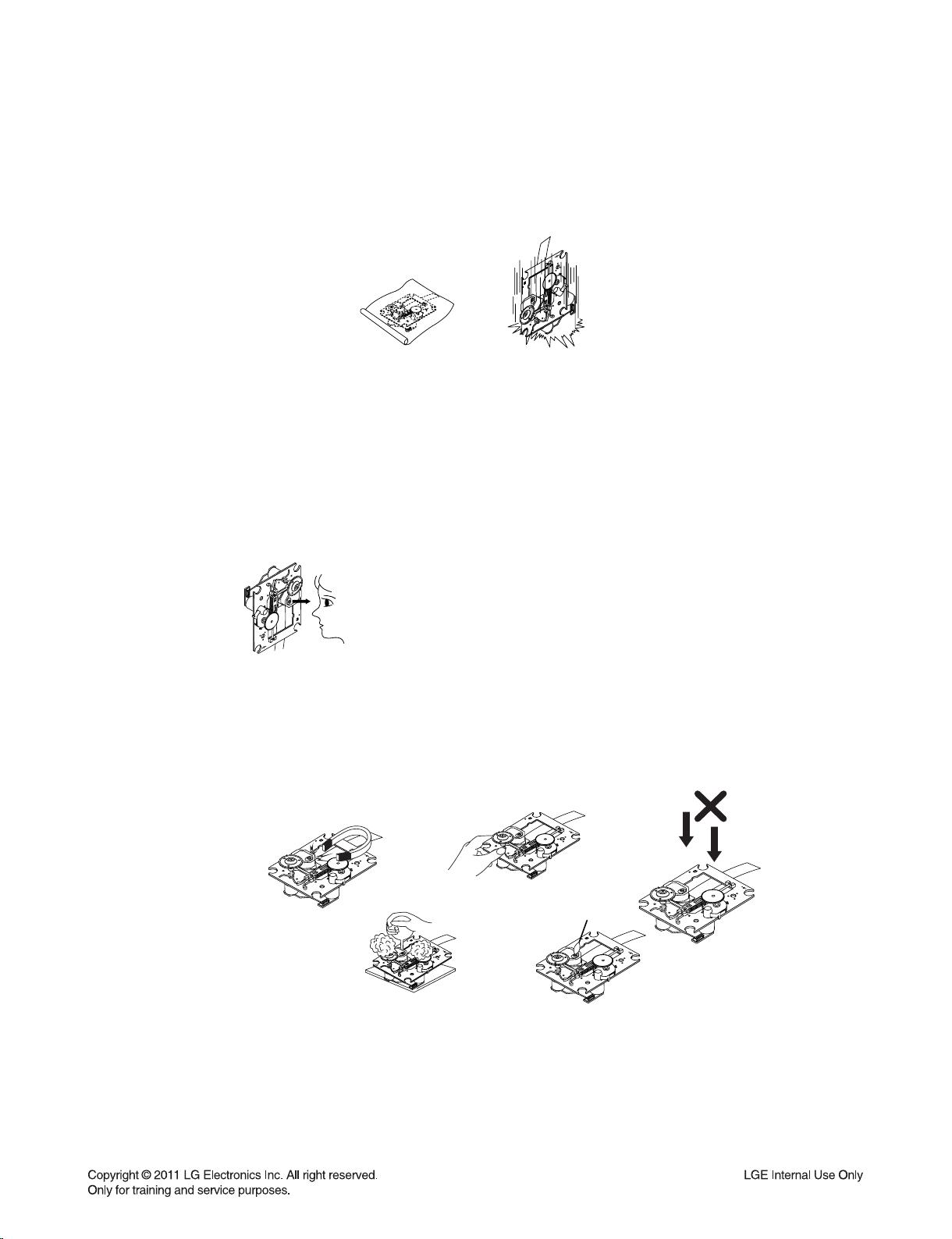
1. Notes for transport and storage
1) The pick-up should always be left in its conductive bag until immediately prior to use.
2) The pick-up should never be subjected to external pressure or impact.
Storage in conductive bag
Drop impact
2. Repair notes
1) The pick-up incorporates a strong magnet, and so should never be brought close to magnetic materials.
2) The pick-up should always be handled correctly and carefully, taking care to avoid external pressure and
impact. If it is subjected to strong pressure or impact, the result may be an operational malfunction and/or
damage to the printed-circuit board.
3) Each and every pick-up is already individually adjusted to a high degree of precision, and for that reason
the adjustment point and installation screws should absolutely never be touched.
4) Laser beams may damage the eyes!
Absolutely never permit laser beams to enter the eyes!
Also NEVER switch ON the power to the laser output part (lens, etc.) of the pick-up if it is damaged.
NEVER look directly at the laser beam, and don’t allow
contact with fingers or other exposed skin.
5) Cleaning the lens surface
If there is dust on the lens surface, the dust should be cleaned away by using an air bush (such as used
for camera lens). The lens is held by a delicate spring. When cleaning the lens surface, therefore, a cotton
swab should be used, taking care not to distort lens.
Pressure
Magnet
How to hold the pick-up
Cotton swab
Conductive Sheet
6) Never attempt to disassemble the pick-up.
Spring has excess pressure. If the lens is extremely dirty, apply isopropyl alcohol to the cotton swab.
(Do not use any other liquid cleaners, because they will damage the lens.) Take care not to use too much
of this alcohol on the swab, and do not allow the alcohol to get inside the pick-up.
1-3
Pressure
NOTES REGARDING COMPACT DISC PLAYER REPAIRS
1. Preparations
1) Compact disc players incorporate a great many ICs as well as the pick-up (laser diode). These components
are sensitive to, and easily affected by, static electricity. If such static electricity is high voltage, components
can be damaged, and for that reason components should be handled with care.
2) The pick-up is composed of many optical components and other high-precision components. Care must be
taken, therefore, to avoid repair or storage where the temperature or humidity is high, where strong magnetism is present, or where there is excessive dust.
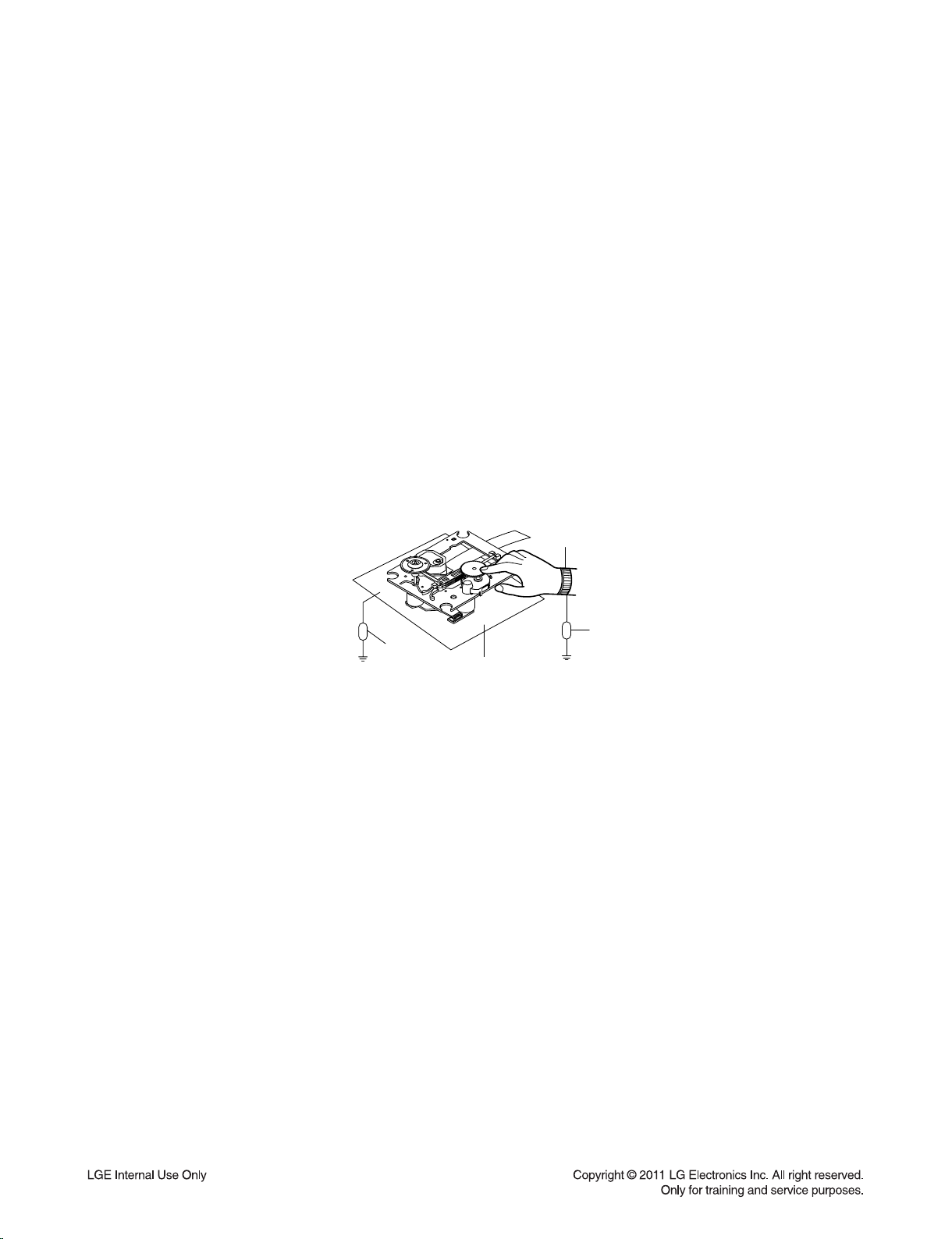
2. Notes for repair
1) Before replacing a component part, first disconnect the power supply lead wire from the unit
2) All equipment, measuring instruments and tools must be grounded.
3) The workbench should be covered with a conductive sheet and grounded.
When removing the laser pick-up from its conductive bag, do not place the pick-up on the bag. (This is
because there is the possibility of damage by static electricity.)
4) To prevent AC leakage, the metal part of the soldering iron should be grounded.
5) Workers should be grounded by an armband (1 MΩ)
6) Care should be taken not to permit the laser pick-up to come in contact with clothing, in order to prevent static electricity changes in the clothing to escape from the armband.
7) The laser beam from the pick-up should NEVER be directly facing the eyes or bare skin.
Armband
Resistor
(1 MΩ)
Resistor
(1 MΩ)
Conductive
Sheet
1-4
ESD PRECAUTIONS
Electrostatically Sensitive Devices (ESD)
Some semiconductor (solid state) devices can be damaged easily by static electricity. Such components
commonly are called Electrostatically Sensitive Devices (ESD). Examples of typical ESD devices are integrated
circuits and some field-effect transistors and semiconductor chip components. The following techniques should
be used to help reduce the incidence of component damage caused by static electricity.
1. Immediately before handling any semiconductor component or semiconductor-equipped assembly, drain off
any electrostatic charge on your body by touching a known earth ground. Alternatively, obtain and wear a
commercially available discharging wrist strap device, which should be removed for potential shock reasons
prior to applying power to the unit under test.
2. After removing an electrical assembly equipped with ESD devices, place the assembly on a conductive surface
such as aluminum foil, to prevent electrostatic charge buildup or exposure of the assembly.
3. Use only a grounded-tip soldering iron to solder or unsolder ESD devices.
4. Use only an anti-static solder removal device. Some solder removal devices not classified as "anti-static" can
generate electrical charges sufficient to damage ESD devices.
5. Do not use freon-propelled chemicals. These can generate electrical charges sufficient to damage ESD
devices.
6. Do not remove a replacement ESD device from its protective package until immediately before you are
ready to install it. (Most replacement ESD devices are packaged with leads electrically shorted together by
conductive foam, aluminum foil or comparable conductive materials).
7. Immediately before removing the protective material from the leads of a replacement ESD device, touch the
protective material to the chassis or circuit assembly into which the device will by installed.
CAUTION : BE SURE NO POWER IS APPLIED TO THE CHASSIS OR CIRCUIT, AND OBSERVE ALL OTHER
SAFETY PRECAUTIONS.
8. Minimize bodily motions when handing unpackaged replacement ESD devices. (Otherwise harmless motion
such as the brushing together of your clothes fabric or the lifting of your foot from a carpeted floor can generate
static electricity sufficient to damage an ESD device).
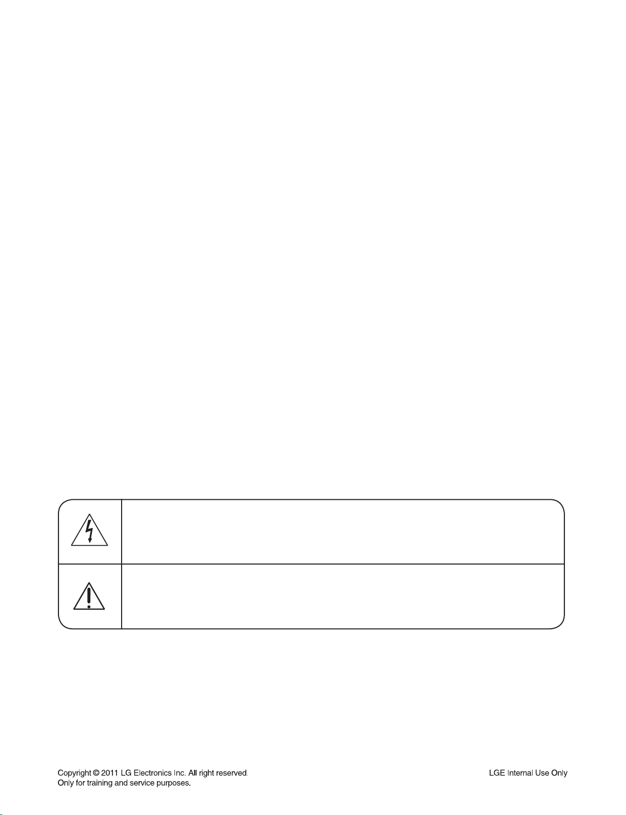
CAUTION. GRAPHIC SYMBOLS
THE LIGHTNING FLASH WITH APROWHEAD SYMBOL. WITHIN AN EQUILATERAL TRIANGLE, IS
INTENDED TO ALERT THE SERVICE PERSONNEL TO THE PRESENCE OF UNINSULATED
“DANGEROUS VOLTAGE” THAT MAY BE OF SUFFICIENT MAGNITUDE TO CONSTITUTE A RISK OF
ELECTRIC SHOCK.
THE EXCLAMATION POINT WITHIN AN EQUILATERAL TRIANGLE IS INTENDED TO ALERT THE
SERVICE PERSONNEL TO THE PRESENCE OF IMPORTANT SAFETY INFORMATION IN SERVICE
LITERATURE.
1-5
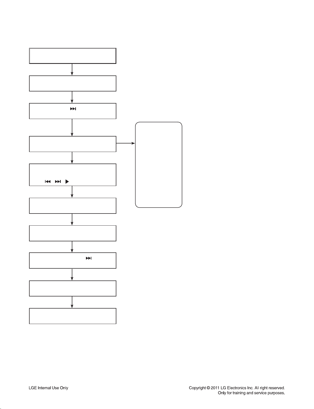
SERVICE INFORMATION FOR EEPROM
POWER ON
FLD no disc status
Remote control ‘
’ + Front ‘STOP’
push same timing during 5s
FLD ‘OP-0….
Move to appropriate position and
make changes with remote control.
( , , /■ , REPEAT )
Press STOP key
FLD ‘write ok’
DETECT NEW EEPROM
(OPTION EDIT SCREEN)
NAME
OP0
OP1
OP2
OP3
OP4
OP5
OP6
OP7
OP8
OP9
HEX
09
00
00
00
00
69
90
05
60
08
Remote control ‘
’ +
Front ‘STOP’ push same timing
FLD ‘E2P CLR’
Completed
1-6
PROGRAM DOWNLOAD GUIDE
1. AUDIO PROGRAM
Download program file name must be RCD406_YYMMDDX.HEX
If security program (Water Wall) is activated on your PC, you must save the file to the usb storage
device and disable the security software, then download the file to your set.
Caution: When downloading the file, you should neither unplug the usb device, change to the other
function, nor power off the device. Usb device must be unplugged when the downloading
process is completed.
ON VFD DISPLAY SCREEN
NO USB
↓← Insert usb device at usb function
READ
↓
FIRMWARE
↓
WRITE 00 .. 100
↓
UPDATED
↓
POWER OFF AUTOMATICALLY
←
When completed, remove usb device.
1-7
2. CD PROGRAM
Download program file name must be HD003_DATE_00.BIN
If security program (Water Wall) is activated on your PC, you must save the file to the usb storage
device and disable the security software, then download the file to your set.
Caution: When downloading the file, you should neither unplug the usb device, change to the other
function, nor power off the device. Usb device must be unplugged when the downloading
process is completed.
ON VFD DISPLAY SCREEN
NO USB
↓← Insert usb device at usb function
READ
↓
FIRMWARE
↓
FINISH
↓
UPDATED
↓
POWER OFF AUTOMATICALLY
←
When completed, remove usb device
.
1-8

3. BEAT BOX PROGRAM
Download program file name must be BEAT_BIN_DATE_00.BIN
If security program (Water Wall) is activated on your PC, you must save the file to the usb storage
device and disable the security software, then download the file to your set.
Caution: When downloading the file, you should neither unplug the usb device, change to the other
function, nor power off the device. Usb device must be unplugged when the downloading
process is completed.
ON VFD DISPLAY SCREEN
NO USB
↓← Insert usb device at usb function
READ
↓
FIRMWARE
↓
FINISH
↓
UPDATED
↓
POWER OFF AUTOMATICALLY
←
When completed, remove usb device
.
1-9

SPECIFICATIONS
• GENERAL
Power requirements Refer to main label
Power consumption Refer to main label
Dimensions (W x H x D) 285 x 350 x 380 mm without foot
Net Weight (Approx.) 6.6 kg
Operating temperature 5 °C to 35 °C (41 °F to 95 °F)
Operating humidity 5 % to 90 %
Bus Power Supply USB DC 5 V 500 mA
iPod DC 5 V 1 A
• INPUTS/ OUTPUTS
ANALOG AUDIO IN 1.2 Vrms (1 kHz, 0 dB), 600 Ω, RCA jack (L, R) x 1
PORT. IN 0.5 Vrms (3.5 mm stereo jack)
ANALOG AUDIO OUT 800 mVrms (1 kHz, 0 dB), 600 Ω, RCA jack (L, R) x 1
• TUNER
FM Tuning Range 87.5 to 108.0 MHz or 87.50 to 108.00 MHz
AM Tuning Range 522 to 1 620 kHz, 520 to 1 710 kHz or 522 to 1 710 kHz
• AMPLIFIER
Stereo mode 200 W + 200 W (4 Ω at 1 kHz)
• CD
Frequency Response 40 to 20 000 Hz
Signal-to-noise ratio 75 dB
Dynamic range 80 dB
• SPEAKERS
Front speaker
Type 2 Way 2 speaker
Impedance 4 Ω
Rated Input Power 200 W
Max. Input power 400 W
Net Dimensions (W x H x D) 239 x 400 x 335 mm
Net Weight 5 kg
• Design and specifications are subject to change without notice.
1-10

SECTION 2
CABINET & MAIN CHASSIS
CONTENTS
DISASSEMBLY AND ASSEMBLY FOR MECHANISM DECK (CDM-H1803) ........................ 2-2
1. ORDER OF DISASSEMBLY FOR MECHANISM DECK .......................................................................... 2-2
2. ORDER OF ASSEMBLY FOR MECHANISM DECK ................................................................................ 2-6
EXPLODED VIEWS ................................................................................................................................... 2-11
1. CABINET AND MAIN FRAME SECTION (RCD406) .............................................................................. 2-11
2. MECHANISM DECK SECTION (CDM-H1803) ....................................................................................... 2-13
3. PACKING ACCESSORY SECTION ....................................................................................................... 2-15
4. SPEAKER SECTION .............................................................................................................................. 2-16
2-1
DISASSEMBLY AND ASSEMBLY FOR MECHANISM DECK (CDM-H1803)
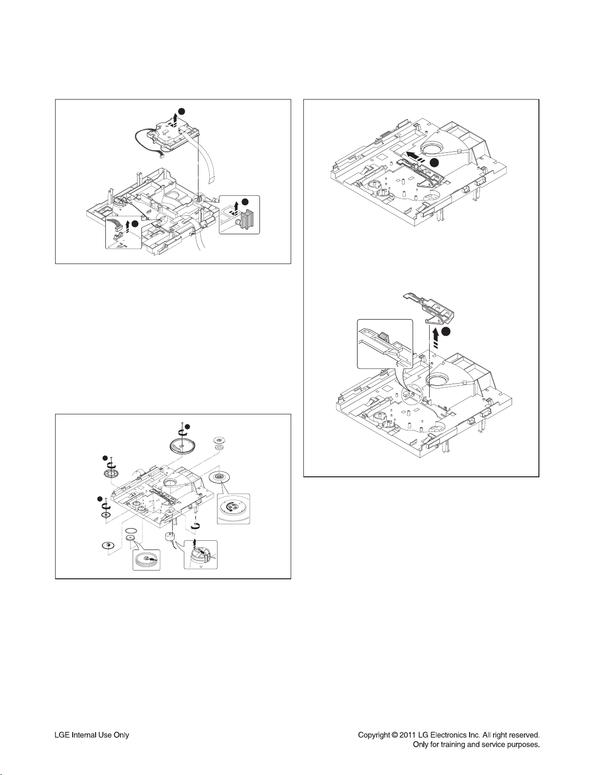
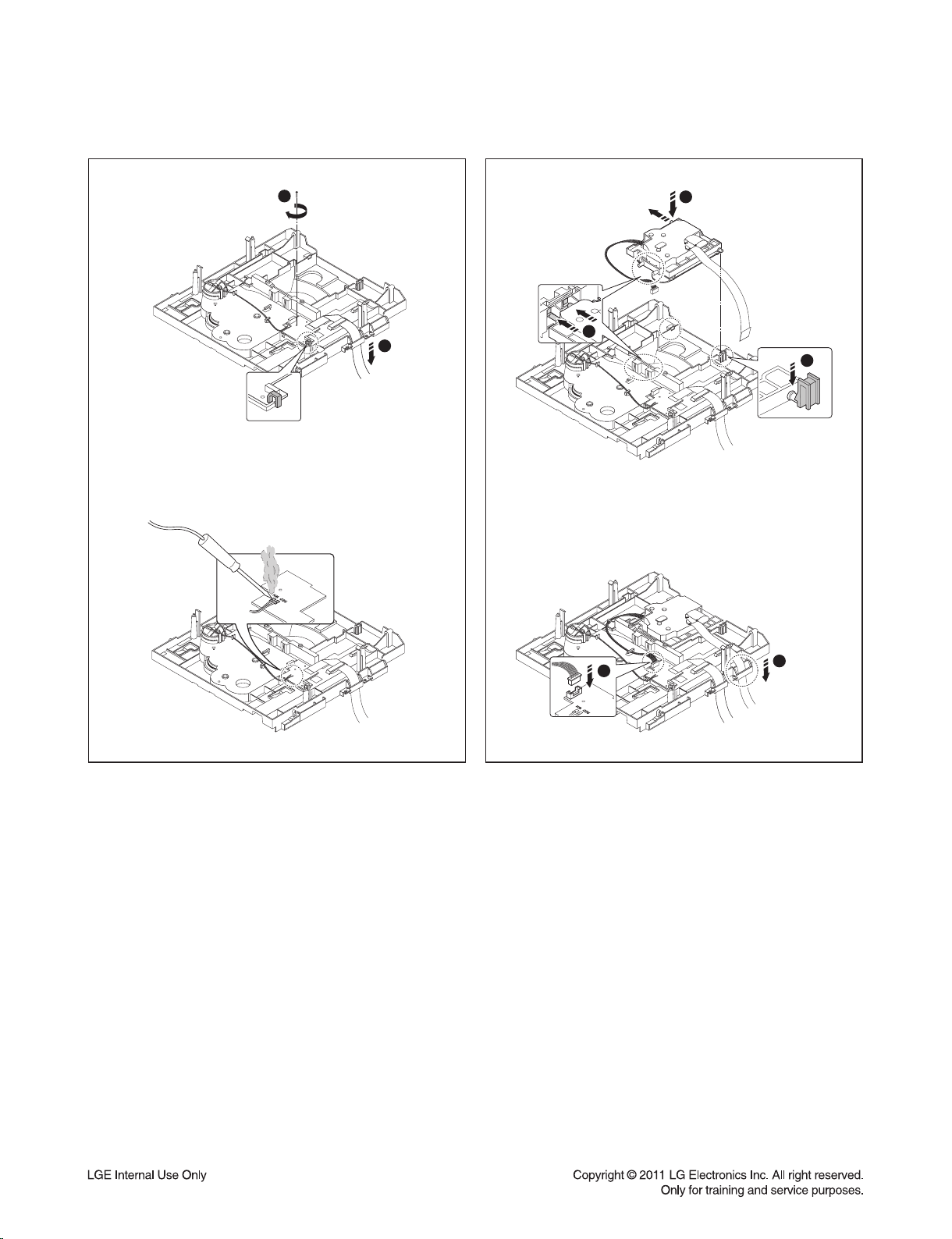
1. ORDER OF DISASSEMBLY FOR MECHANISM DECK
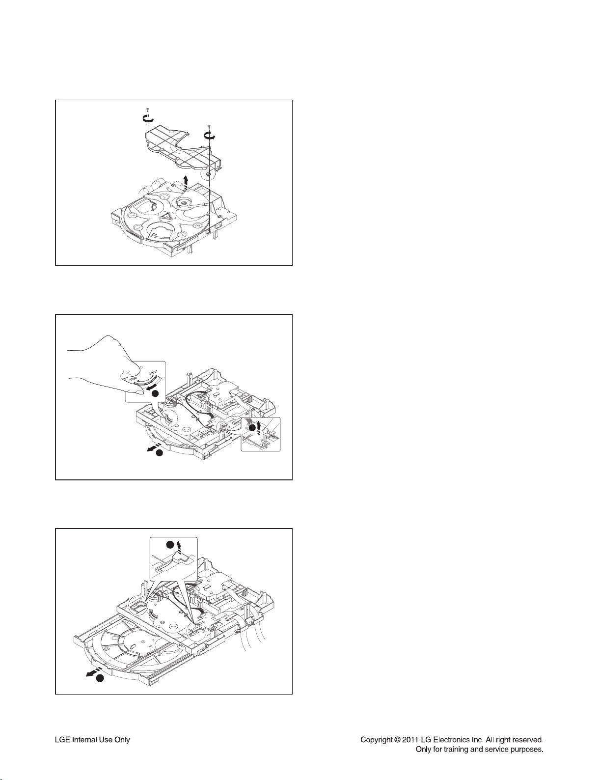
1) Disassemble the Cover Guide Disc.
Figure 1
2) Disassemble the Loading FFC from the Main PCB
Assy.
Turn the Gear in OPEN direction as shown in Figure 2
to take out the Tray Loading Assy in 3 direction.
2
1
3
Figure 2
3) Pull up the Holder 1 to completely disassemble the
1
2
Tray Loading Assy from the Base Main Assy.
Figure 3
2-2
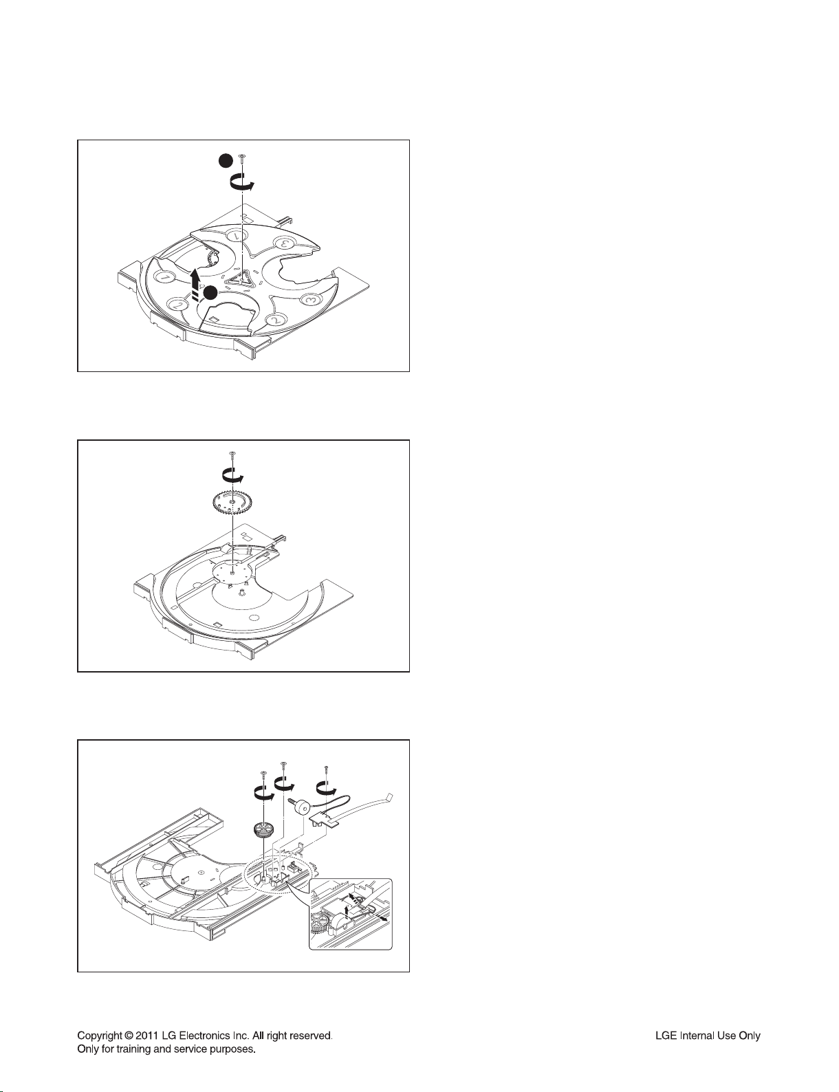
ORDER OF DISASSEMBLY FOR MECHANISM DECK
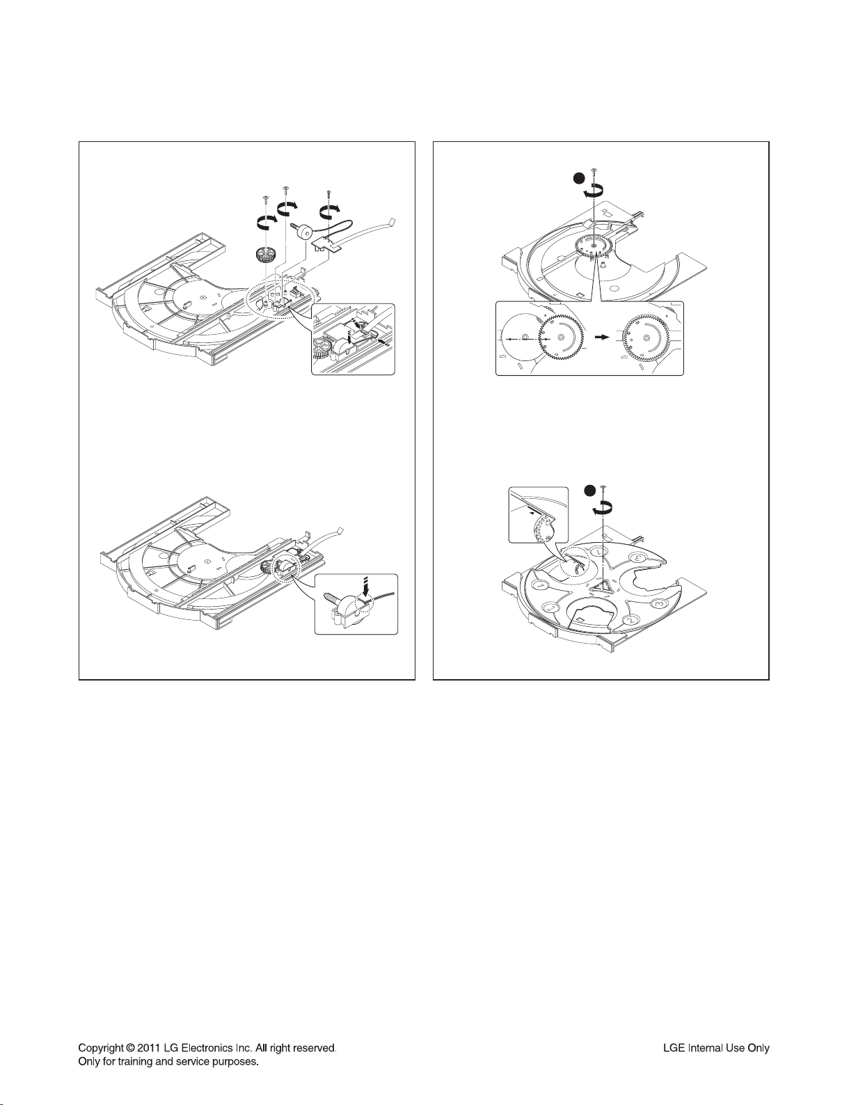
4) Loosen the screw to pull up and disassemble the
1
2
Figure 4
Tray Disc.
5) Loosen the screw to pull up and disassemble the
Gear Tray CAM.
Figure 5
Figure 6
6) Disassemble the Gear Tray, Tray Motor Assy and
Loading PCB Assy from the Tray Loading.
2-3
ORDER OF DISASSEMBLY FOR MECHANISM DECK
3
2
1
Figure 7
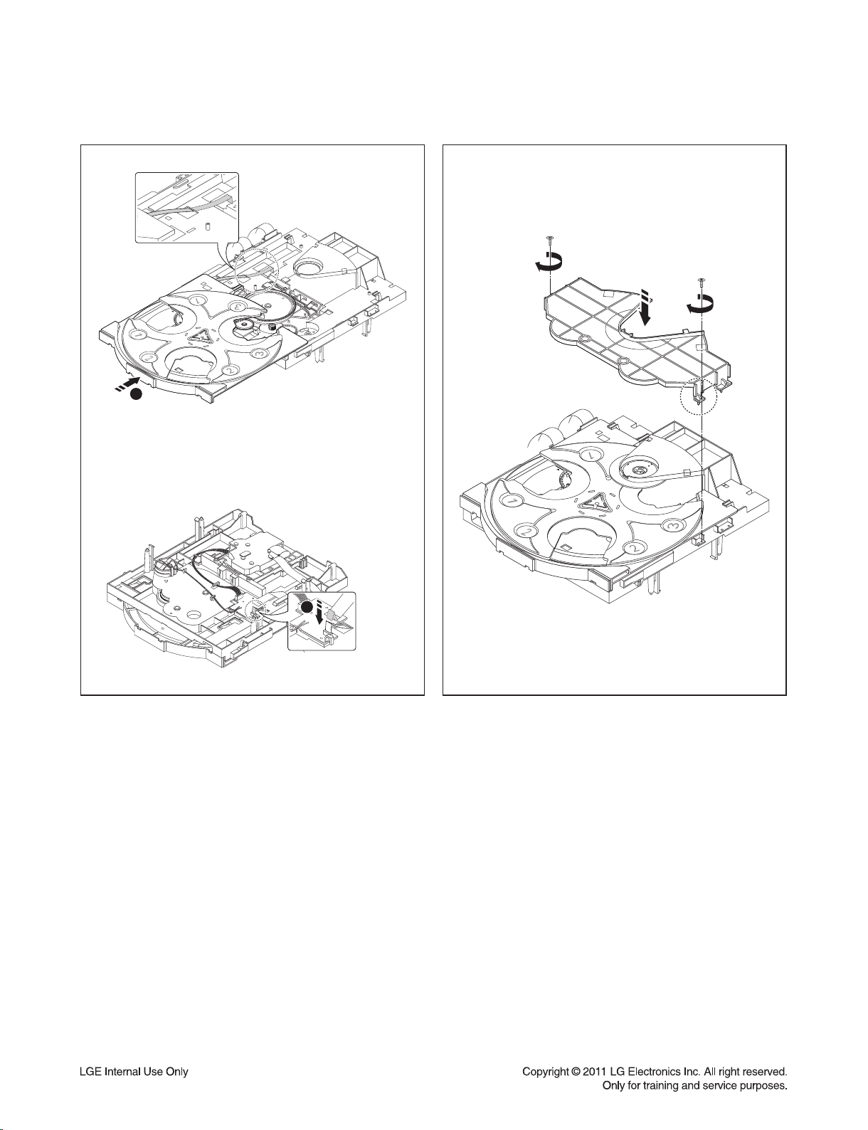
7) Disassemble the Harness Cable from the Base
Main.
Disassemble the Base Sled Assy from the Base Main
by referring to Figure.
1
2
3
1
2
Figure 8
8) Disassemble each gear part, Clamp Disc, Clamp
Magnet and Cover Plate from the Base Main.
Disassemble the Loading Motor Assy by being careful
of the hook on the surface of the Base Main.
Figure 9
9) Push the Guide UD in direction 1 to disassemble it
from the Base Main.
2-4
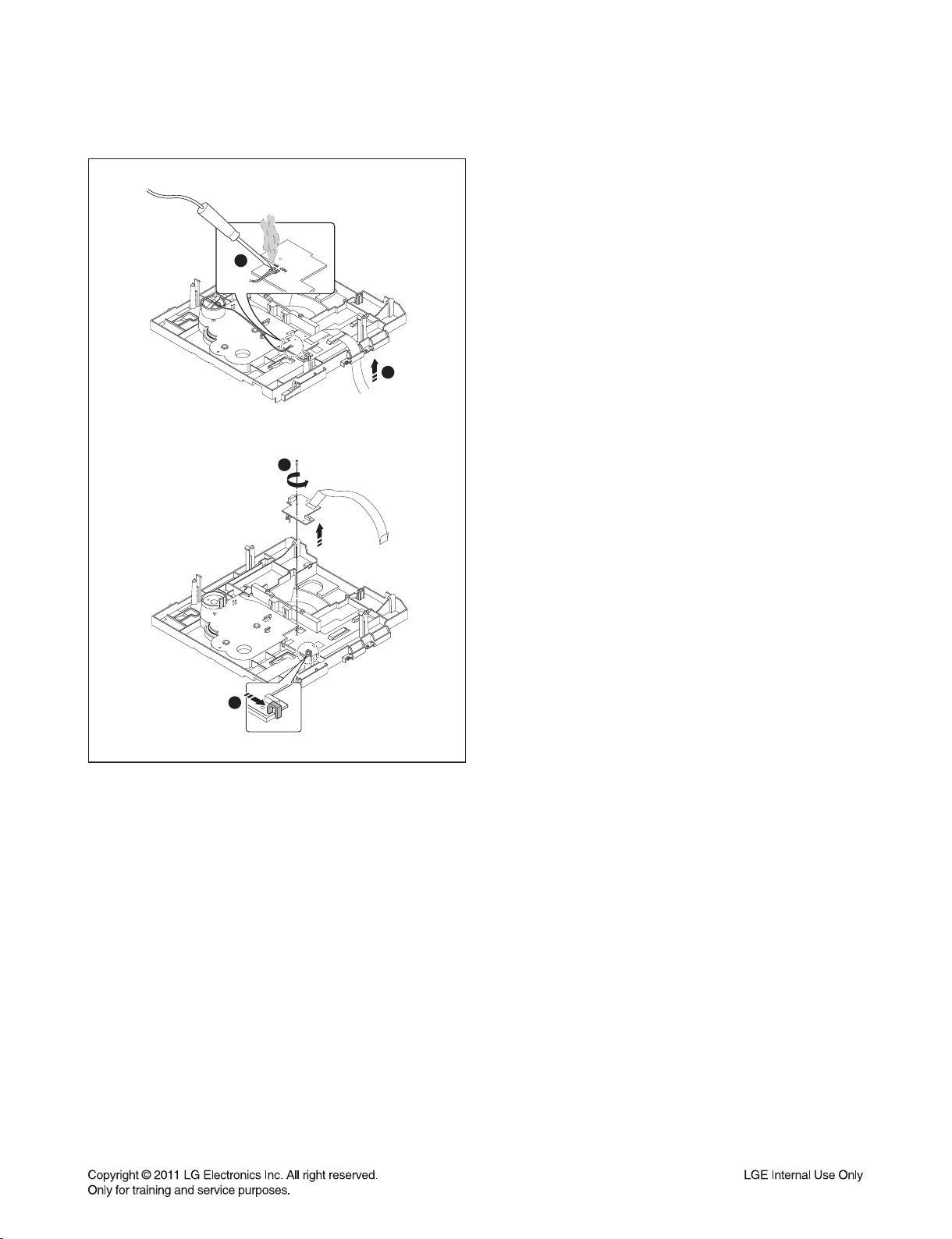
ORDER OF DISASSEMBLY FOR MECHANISM DECK
10) Use a solder to remove the Motor Jump Wire from
the Main PCB Assy and then disassemble the FFC
Cable.
Loosen the screw to disassemble the Main PCB Assy.
1
2
4
3
Figure 10
2-5
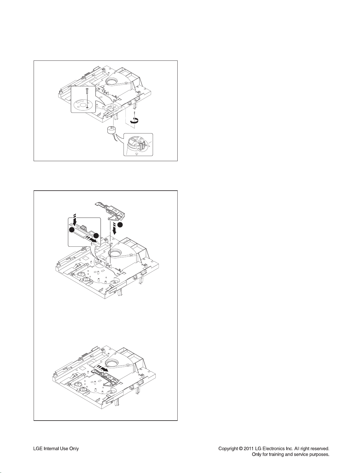
2. ORDER OF ASSEMBLY FOR MECHANISM DECK
1) Assemble the Loading Motor Assy to the Base
Main.
(When assembling the Motor Assy, use the hook on
the surface of the Base Main to preassemble, and then
tighten the screws.)
Figure 1
2) Set the Guide UD on the Base Main.
After setting the part, push it in direction 3.
2
3
1
Figure 2
2-6
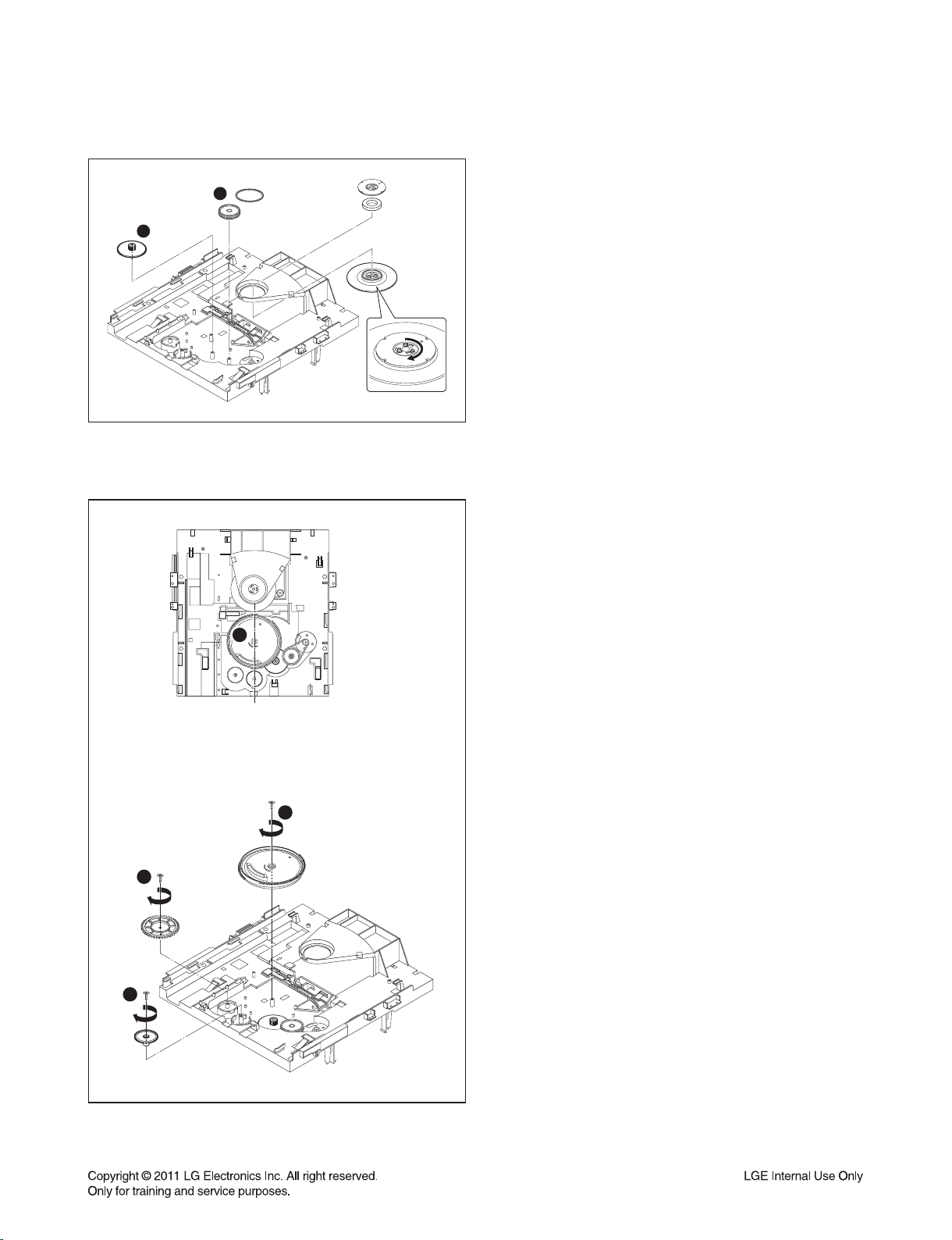
ORDER OF ASSEMBLY FOR MECHANISM DECK
3) Set the Gear Loading 1 and Gear Pulley 2 on the
2
1
Figure 3
Base Main.
Hang the belt between the Gear Pulley and Motor Pulley.
Assemble the Clamp Disc, Clamp Magnet and Cover
Plate to the Base Main.
4) After setting the Gear Main 2, Gear Pu Up 3 and Gear
Pu Down 4 on the Base Main, tighten the screws.
After assembling the Gear Main, align the location as
shown in Figure.
1
2
4
3
Figure 4
2-7
ORDER OF ASSEMBLY FOR MECHANISM DECK
1
1
2
2
3
Figure 5
5) After setting the Main PCB Assy on the Base Main,
tighten the screw.
(Set the part accurately on the hook)
Solder the Motor Jump Wire on the PCB set on the
Base Main.
5
4
Figure 6
6) Set the Base Sled Assy on the Base Main.
(When setting the part, assemble with the CAM part of
the Guide UD inserted in two locations of the Boss of
Frame UD)
Align the FFC to the Guide and connect the Harness
Cable.
2-8
ORDER OF ASSEMBLY FOR MECHANISM DECK
1
2
Figure 7
7) After setting the Gear Tray, Tray Motor Assy and
Loading PCB Assy on the Tray Loading, tighten the
screw.
Figure 8
8) Assemble the Gear Tray CAM on the Tray Loading
and set the Tray Disc.
(When assembling, check the location of the Gear Tray
CAM and Tray Disc as shown in the Figure)
2-9
ORDER OF ASSEMBLY FOR MECHANISM DECK
1
2
3
Figure 9 Figure 10
9) Assemble the Tray Loading Assy on the Base Main
Assy as shown in the Figure.
After assembling, insert the Loading FFC to the 5 Pin
Wafer of Main PCB Assy.
10) After setting the Cover Guide Disc, tighten the
screw.
2-10
EXPLODED VIEWS
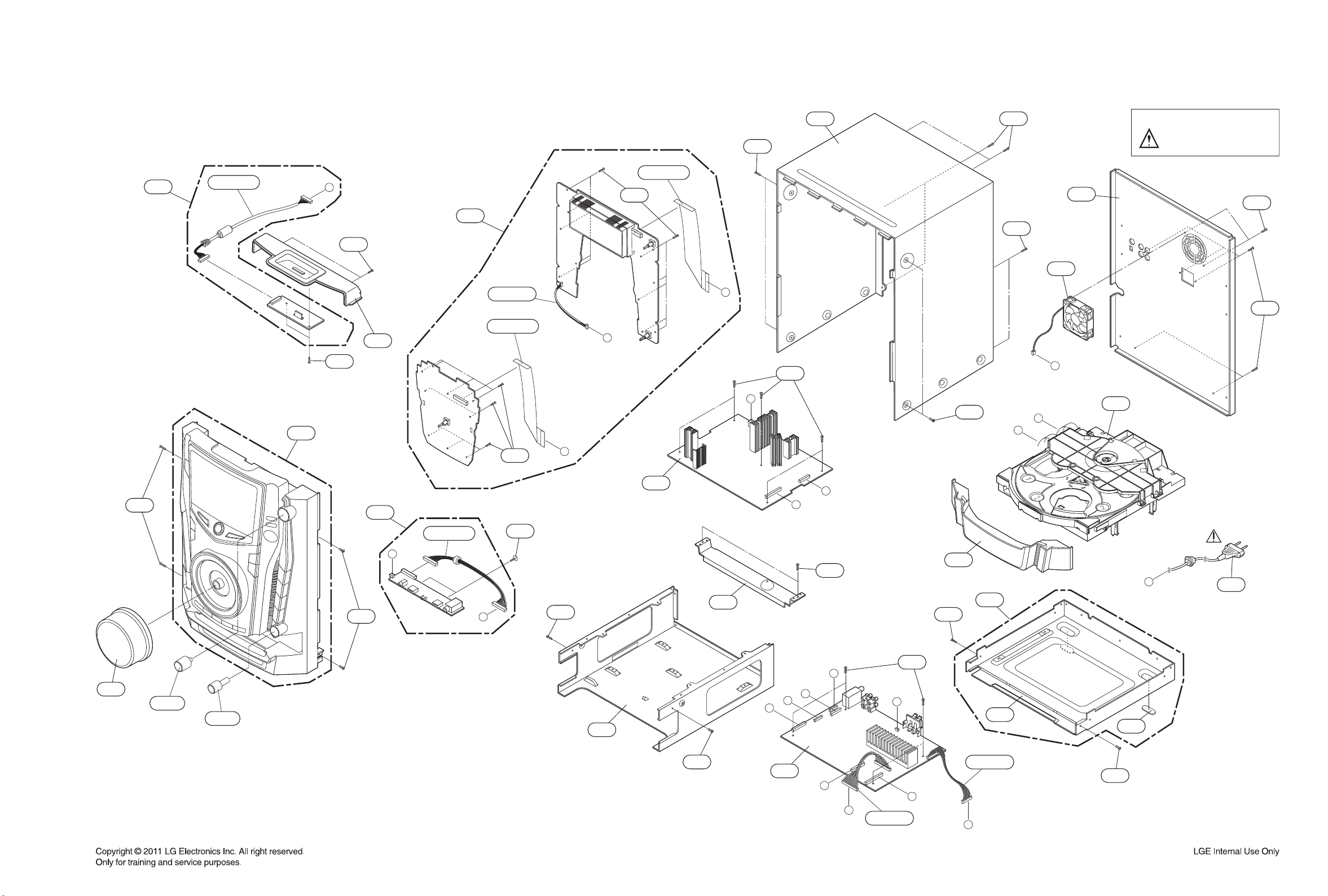
1. CABINET AND MAIN FRAME SECTION (RCD406)
464
A49
CABLE1
A42
E
iPod
464
464
264
A45
A43
VOLUME
CABLE2
CN302
CABLE7
464
480
NOTES) THE EXCLAMATION POINT WITHIN AN
EQUILATERAL TRIANGLE IS INTENDED
TO ALERT THE SERVICE PERSONNEL
TO THE PRESENCE OF IMPORTANT
SAFETY INFORMATION IN SERVICE
LITERATURE.
464
268
464
CABLE6
270
464
VFD
464
464
269
I
464
K
463
C
464
F
H
J
A26
D
SMPS
A47
A
B
251
255A
255C
464
K
USB+MIC
463
267
C
G
464
464
265
A44
300
463
D
E
266
F
G
J
271
272
MAIN
464
A46
H
B
CN102
I
CN101
464
A
2-11 2-12
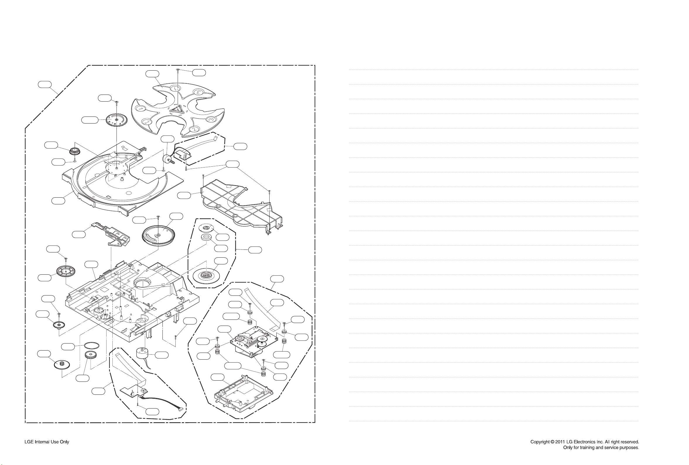
2. MECHANISM DECK SECTION (CDM-H1803)
MEMO
A26
153
443
159
173
153A
443
416
151
443
416
155
156
422
182
177
001
166
167
164
417
417
162
163
172
165
422
175
440
421
012
002
003
180
012B
137
421
012
012A
A02
A01
010
421
012
012B
421
012
2-13 2-14
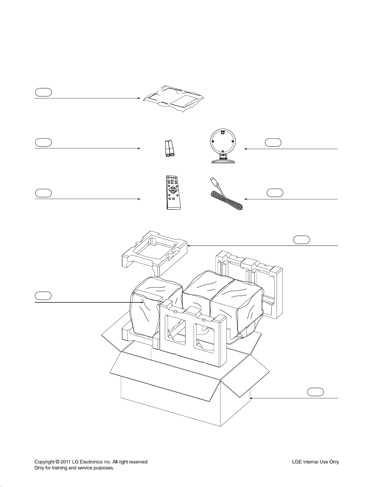
3. PACKING ACCESSORY SECTION
801 Owner’s Manual
AAA
808 Battery
AAA
824 AM Loop Antenna
900 Remote Control
804 Bag
825 FM Wire Antenna
803 Packing
2-15
802 Box
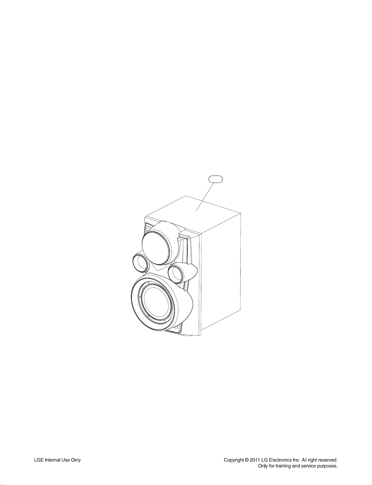
4. SPEAKER SECTION
4-1. FRONT SPEAKER (RCS606F)
A60
2-16

SECTION 3 ELECTRICAL
CONTENTS
TRAINING MASTER ................................................................................................................................... 3-2
1. NO SOUND FROM SPEAKERS ............................................................................................................ 3-2
2. NO SOUND IN AUX FUNCTION ............................................................................................................ 3-3
3. NO SOUND IN PORT. IN FUNCTION ................................................................................................... 3-4
4. NO SOUND IN IPOD FUNCTION .......................................................................................................... 3-5
5. NO SOUND IN AM/FM FUNCTION ....................................................................................................... 3-6
6. NO SOUND IN CD FUNCTION .............................................................................................................. 3-7
7. NO SOUND IN USB FUNCTION ............................................................................................................ 3-9
8. NO POWER .......................................................................................................................................... 3-10
ONE POINT REPAIR GUIDE ................................................................................................................. 3-11
1. NO POWER .......................................................................................................................................... 3-11
2. NO BOOTING WHEN POWER ON THE SET ..................................................................................... 3-13
3. VFD IS NOT DISPLAYED WHEN POWER ON THE SET ................................................................... 3-14
4. NO OPERATION OF MD ..................................................................................................................... 3-15
5. NO SOUND .......................................................................................................................................... 3-21
ELECTRICAL TROUBLESHOOTING GUIDE .................................................................................. 3-29
1. POWER SUPPLY ON SMPS BOARD ................................................................................................. 3-29
2. SYSTEM PART .................................................................................................................................... 3-33
3. NO AUDIO PART ................................................................................................................................. 3-34
4. DIGITAL AUDIO AMP CHECK ............................................................................................................. 3-39
WAVEFORMS ............................................................................................................................................. 3-40
WIRING DIAGRAM ................................................................................................................................... 3-43
BLOCK DIAGRAMS ................................................................................................................................. 3-45
1. OVERALL BLOCK DIAGRAM .............................................................................................................. 3-45
2. SMPS BLOCK DIAGRAM..................................................................................................................... 3-47
3. POWER BLOCK DIAGRAM ................................................................................................................. 3-49
CIRCUIT DIAGRAMS ............................................................................................................................... 3-51
1. SMPS CIRCUIT DIAGRAM .................................................................................................................. 3-51
2. MICOM CIRCUIT DIAGRAM ................................................................................................................ 3-53
3. PWM CIRCUIT DIAGRAM .................................................................................................................... 3-55
4. AMP CIRCUIT DIAGRAM ..................................................................................................................... 3-57
5. DSP CIRCUIT DIAGRAM ..................................................................................................................... 3-59
6. RF SERVO CIRCUIT DIAGRAM .......................................................................................................... 3-61
7. ADC CIRCUIT DIAGRAM ..................................................................................................................... 3-63
8. BEAT BOX CIRCUIT DIAGRAM .......................................................................................................... 3-65
9. VFD CIRCUIT DIAGRAM ..................................................................................................................... 3-67
10. VOLUME CIRCUIT DIAGRAM ............................................................................................................. 3-69
11. USB & MIC CIRCUIT DIAGRAM .......................................................................................................... 3-71
12. IPOD CIRCUIT DIAGRAM .................................................................................................................... 3-73
CIRCUIT VOLTAGE CHART ................................................................................................................. 3-75
PRINTED CIRCUIT BOARD DIAGRAMS ......................................................................................... 3-79
1. MAIN P.C.BOARD ................................................................................................................................ 3-79
2. SMPS P.C.BOARD ............................................................................................................................... 3-83
3. VFD P.C.BOARD .................................................................................................................................. 3-85
4. VOLUME P.C.BOARD .......................................................................................................................... 3-87
5. USB & MIC P.C.BOARD ...................................................................................................................... 3-89
6. IPOD P.C.BOARD ................................................................................................................................ 3-89
3-1
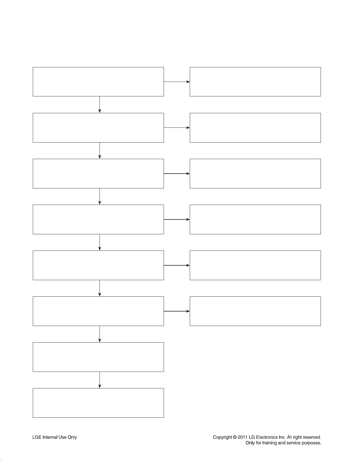
TRAINING MASTER
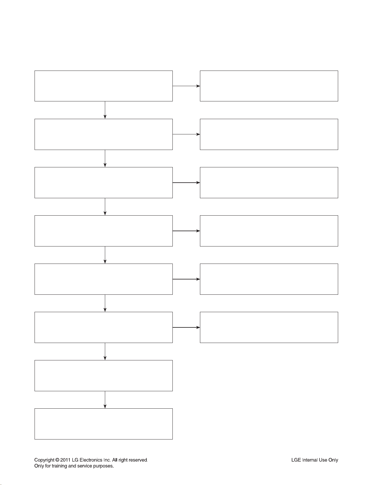
1. NO SOUND FROM SPEAKERS
Are the speaker cables connected correctly
between the speaker terminals on the unit
and the speakers?
YES
Does the customer select correctly
the input function he or she wants to listen to?
YES
After pressing FUNCTION,
is “CD, USB, AUX, IPOD, AM or FM” displayed?
YES
Turn the master volume clockwise
for the volume up.
YES
NO
NO
NO
NO
Make sure to connect the cables to each specified
connector tightly on the unit.
Connect the woofer cables to the WOOF SYSTEM
connectors on the rear panel.
Make sure to connect some cables like A/V cables
and FM/AM antenna cables.
Make sure to select the desired input function
pressing FUCTION button.
The volume level LEDs around the master volume
will be turned on more and more
while turning it clockwise for the volume up.
Is there any sound from the selected input source?
(AUX IN, USB, TUNER or CD Disc)
YES
Are the sound spectrum level LEDs
on the left and right side of the front panel
being changed up and down
according to the sound input gain?
YES
The sound is output from the speakers.
YES
Sound OK
NO
NO
Refer to a device’s instruction manual
and then check if there is sound output from it
connecting another audio system.
The sound spectrum level LEDs will be turned on/off
repeatedly at regular intervals. The speakers cables
might be short-circuited with the chassis ground.
Be careful not to be shorted each other.
3-2
TRAINING MASTER
2. NO SOUND IN AUX FUNCTION
Does the customer select correctly
the AUX function he or her wants to listen to?
YES
After pressing the FUNCTION,
is “AUX” displayed on VFD?
YES
Turn the master volume clockwise
for the volume up.
YES
Is there any sound
from the selected input source?
YES
NO
NO
NO
NO
Make sure to connect some cables
between the AUX IN jacks of the unit
and the Audio output jacks of a external Audio device.
Make sure to select the AUX IN function
pressing the AUX/IPOD/PORT. IN button.
The volume level LEDs around the master volume
will be turned on more and more
while turning it clockwise for the volume up.
Refer to a device’s instruction manual
and then check if there is sound output
from it connecting another audio system
Are the sound spectrum level LED’s
on the left and right side of the front panel
being changed up and down
according to the sound input gain?
YES
Are the speaker cables connected correctly
between the speaker terminals on the unit
and the speakers?
YES
The sound is output
from the speakers.
YES
Sound OK
NO
NO
The sound spectrum level LED’s will be turned on/off
repeatedly at regular intervals. A speaker cable
might be short-circuited with the chassis ground.
Be careful not to be shorted each other.
Make sure to connect the cables to each specified
connector tightly on the unit.
Connect the woofer cables to the WOOF SYSTEM
connectors on the rear panel.
3-3
 Loading...