

Page 1
External Equipment Connection and Viewing Setup
S-VIDEO VIDEO
- AUDIO -
L/MONO
R
IN 3
S-VIDEO VIDEO
- AUDIO -
L/MONO
R
IN 3
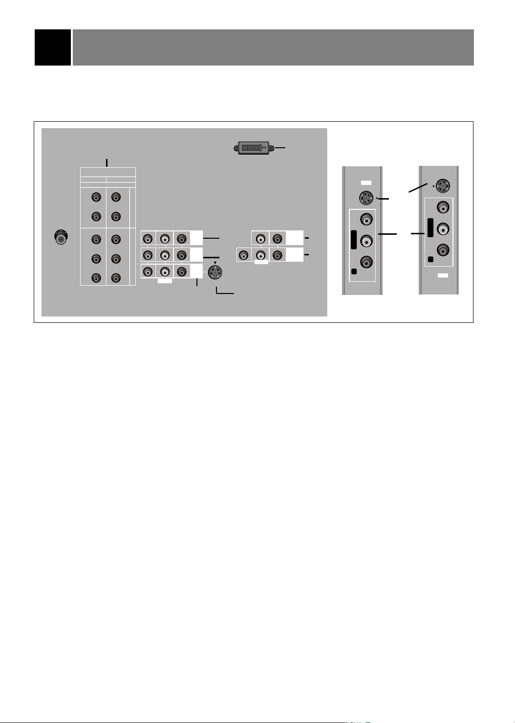
You can connect additional equipment, such as VCRs, camcorders etc. to your TV.
Connection panels shown here may be somewhat different from your TV.
Here is an example drawing of a typical jackpack layout.
8
VARIABLE
AUDIO OUTPUT
IN 4
S-VIDEO
INPUT
JACK
6
3
4
ANT IN
L
L
75Ω
DVD/DTV INPUT
COMPONENT 1
(480i/480p/1080i)
(R)
(L)
PR
PB
Y
7
COMPONENT 2
DVI-HDTV INPUT
(R)
AUDIO
(L)
(L)-AUDIO-(R)
VIDEO
PR
PB
VIDEO
Y
MONO
MONITOR
OUTPUT
IN 2
DVI
( )
AUDIO
IN 1
5
2
S - VIDEO
1
(L)-AUDIO-(R)
VIDEO
MONO
S-VIDEO INPUT JACK
1. IN 1 JACKS : Connect external equipment outputs (VCR, DVD, CAMCORDER) to these
inputs. Press the tv/video button repeatedly to select
Video 1.
2. IN 2 JACKS : Connect external equipment outputs (VCR, DVD, CAMCORDER) to these inputs. Press
the tv/video button repeatedly to select
Video 2.
3. IN 3 JACKS : Connect external equipment outputs (VCR, DVD, CAMCORDER) to these inputs. Press
the tv/video button repeatedly to select
Video 3.
4. IN 4 JACKS : Connect external equipment outputs (VCR, DVD, CAMCORDER) to these inputs. Press
the tv/video button repeatedly to select
Video 4.
5. MONITOR OUTPUT JACKS : Connect a second TV or a monitor to these outputs to observe the
selected program.
6. VARIABLE AUDIO OUT JACKS: Connect external analog stereo amplifier and use external front
speakers.
7. DVD/DTV INPUT JACKS : Connect component output jacks to these inputs. Use the tv/video or
comp/dvi button to select
Component 1, Component 2 sources. Your set-top
devices may be used if they have a DVI-HDTV output connector that supports the
proper version of DVI and HDCP.
8. DVI-HDTV INPUT JACK: Connect a set-top box to this input. Use the tv/video or comp/dvi button to
select
DVI.
Note : Avoid having a stationary fixed image remain on the screen for a long period of time. Typically a
frozen still picture from a VCR. If allowed to remain on the screen ; a fixed image may remain
visible on the screen.
EZ Notice: Make A/V Connection
You can only select connected input sources with the tv/video or comp/dvi button on the remote control.
(It’s not available in DVI input source.)
29
 Loading...